

Page 1
UG308: Thunderboard EFM8UB3 User's
Guide
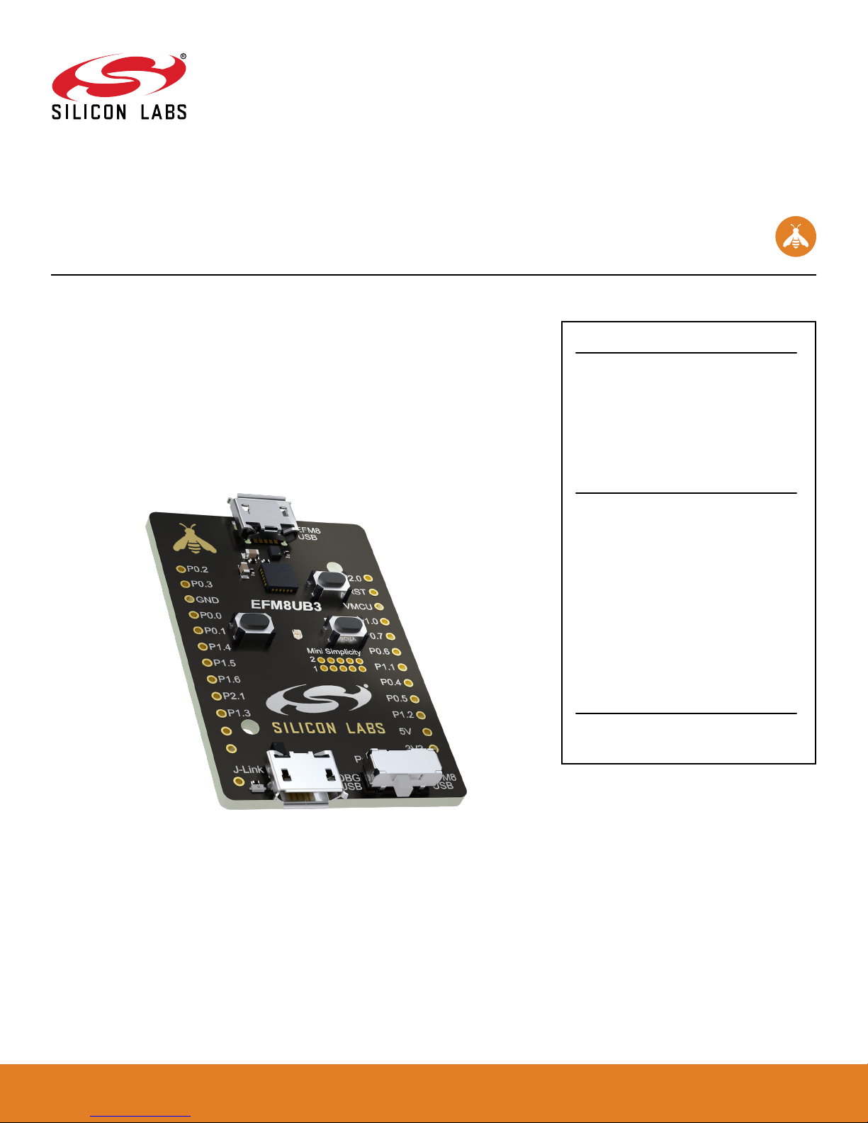
The Thunderboard EFM8UB3 is a low cost, small form factor development and evaluation platform for the EFM8™ Universal Bee
Microcontroller.
The Thunderboard contains an EFM8UB3 MCU together with an on-board SEGGER JLink debugger for easy debugging through the USB Micro-B debugging connector. All of
the EFM8 I/Os are routed to breakout pads on the sides of the board making it easy to
expand on the board features and evaluate the EFM8 Universal Bee's features with custom hardware.
TARGET DEVICE
• EFM8 Universal Bee Microcontroller
(EFM8UB31F40G-A-QFN24)
• Pipelined 8-bit C8051 core with 48 MHz
maximum operating frequency
• 40 kB flash memory and 3328 bytes RAM
• USB feature set
KIT FEATURES
• USB connectivity
• SEGGER J-Link on-board debugger
• Virtual COM port
• User RGB LED and pushbuttons
• 2.54 mm breakout pads to EFM8
• Flat flexible cable connector for external
Silicon Labs "postage-stamp" sized
boards
• Optional Mini-Simplicity connector for
Advanced Energy Monitoring using
external Silicon Labs debugger
SOFTWARE SUPPORT
• Simplicity Studio™
silabs.com
| Building a more connected world. Rev. 1.0
Page 2

Table of Contents
1. Introduction ................................3
1.1 Kit Contents ..............................3
1.2 Getting Started .............................3
1.3 Kit Hardware Layout............................3
2. Electrical Specifications ...........................4
2.1 Absolute Maximum Ratings .........................4
3. Hardware .................................5
3.1 Block Diagram..............................5
3.2 Power Supply ..............................6
3.2.1 Self-Powered Mode ..........................6
3.2.2 Bus-Powered Mode ..........................6
3.3 Universal Serial Bus ............................7
3.4 Push Buttons and RGB LED .........................7
3.5 On-board Debugger ............................8
3.6 EFM8 Reset ..............................8
3.7 Connectors ...............................9
3.7.1 Breakout Pads ...........................10
3.7.2 Mini Simplicity Connector ........................11
3.7.3 EFM8 USB Micro-B Connector ......................11
3.7.4 Debug USB Micro-B Connector ......................11
3.7.5 Flat Flexible Cable Connector ......................12
4. Debugging ............................... 13
4.1 On-board Debugger Considerations ......................13
4.2 Virtual COM Port .............................14
4.3 Mini Simplicity Connector ..........................14
5. Kit Configuration and Upgrades ....................... 15
5.1 Firmware Upgrades ............................15
6. Schematics, Assembly Drawings and BOM ................... 16
7. Kit Revision History and Errata ....................... 17
7.1 Revision History .............................17
7.2 Errata ................................17
8. Board Revision History and Errata ...................... 18
8.1 Revision History .............................18
8.2 Errata ................................18
9. Document Revision History ......................... 19
silabs.com
| Building a more connected world. Rev. 1.0 | 2
Page 3
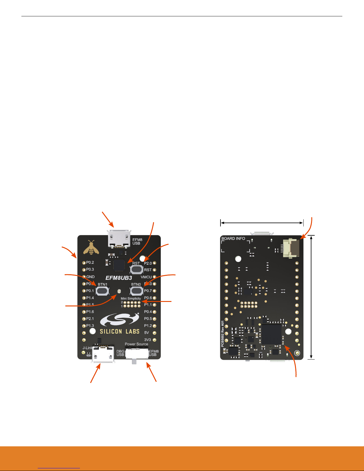
30 mm
45 mm
USB Micro-B Debug Connector
- Virtual COM port
- Debug access
Breakout Pads
USB Micro-B Connector
- Connected to EFM8
Reset Button
Push Button 1
Push Button 0
Mini Simplicity
Connector
Power Source
Slide Switch
EFM8
Universal Bee 3
On-board USB
J-Link Debugger
Top view
Bottom view
Flat Flexible Cable
Connector
RGB LED
{
2.54 mm pitch
UG308: Thunderboard EFM8UB3 User's Guide
Introduction
1. Introduction
The Thunderboard EFM8UB3 (OPN: SLTB005A) is an excellent starting point to get familiar with the EFM8 Universal Bee Microcontrollers. The Thunderboard contains an EFM8UB3 MCU together with an on-board SEGGER J-Link debugger for easy programming and
debugging through the USB Micro-B debug connector. The debugger also provides a USB virtual COM port for serial connection to the
target application.
All of the EFM8 I/Os are routed to breakout pads on the sides of the board making it easy to expand on the board features and evaluate
the EFM8 Universal Bee's features with custom hardware.
1.1 Kit Contents
The following items are included in the box:
• 1x Thunderboard EFM8UB3 board (BRD5002A)
• 1x Micro USB 2.0 to USB A male cable
1.2 Getting Started
Detailed instructions for how to get started with your new Thunderboard EFM8UB3 can be found on the Silicon Labs web pages:
http://www.silabs.com/start-efm8
1.3 Kit Hardware Layout
The layout of the Thunderboard EFM8UB3 is shown below.
Figure 1.1. Thunderboard EFM8UB3 Hardware Layout
silabs.com | Building a more connected world. Rev. 1.0 | 3
Page 4
UG308: Thunderboard EFM8UB3 User's Guide
Electrical Specifications
2. Electrical Specifications
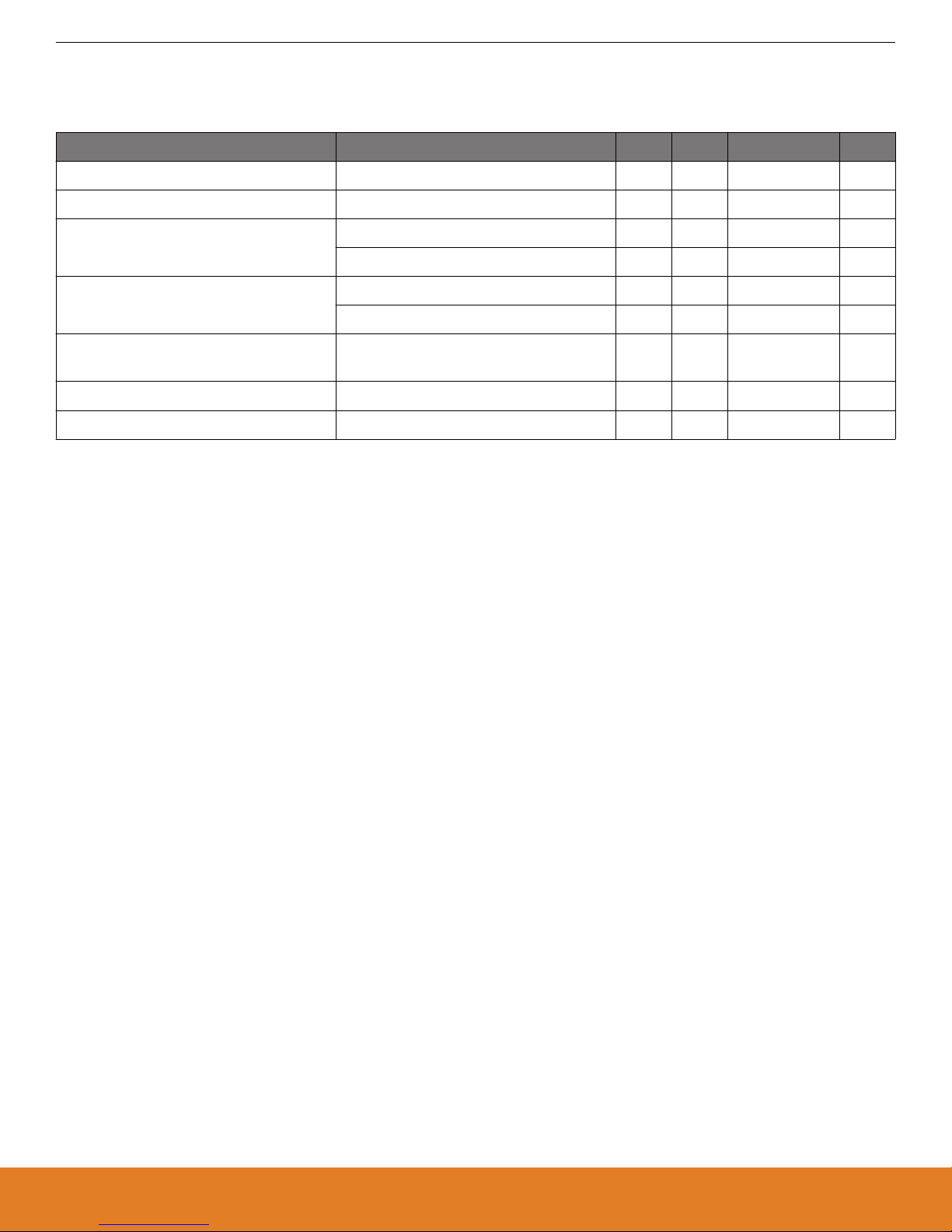
2.1 Absolute Maximum Ratings
Parameter Condition Min Typ Max Unit
Input voltage on EFM8 USB connector -0.3 - +5.8 V
Input voltage on debug USB connector 0 - +5.5 V
Output current Power-Source switch = EFM8 USB - - 100 mA
Power-Source switch = DBG USB - - 300 mA
Voltage on any breakout pad (excluding
P0.4, P0.5, P2.0 and RST)
Voltage on P0.4, P0.5, P2.0 and RST
breakout pad
1
VMCU > 3.3 V -0.3 - 5.8 V
VMCU < 3.3 V -0.3 - VMCU + 2.5 V
-0.3 - VMCU + 0.3 V
Current per EFM8 I/O pin -100 - 100 mA
Total current for all EFM8 I/O pins -400 - 400 mA
1 Limited by the debugger.
silabs.com | Building a more connected world. Rev. 1.0 | 4
Page 5
3. Hardware
Mini-Simplicity
Connector
(Not mounted)
EFM8UB3
Microcontroller
USB Micro-B
Connector
J-Link
Debugger
USB Micro-B
Connector
Power Source
Switch
Power
User Buttons
& RGB LED
Breakout Pads
(EXP-Header pinout)
Flat Flexible
Cable Connector
DBG USB VBUS
EFM8 USB VBUS
C2 Debug
Virtual COM
USB
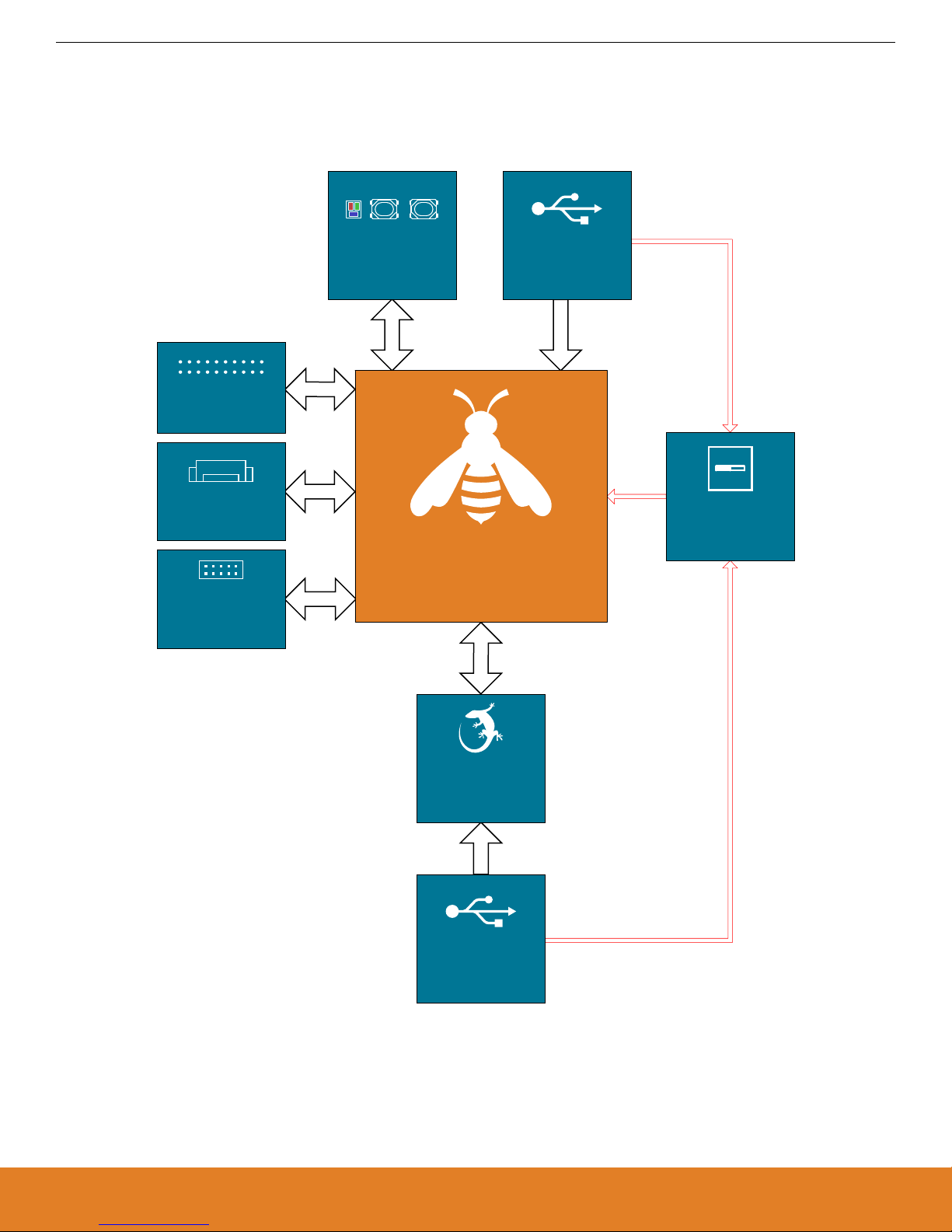
3.1 Block Diagram
An overview of the Thunderboard EFM8UB3 is illustrated in the figure below.
UG308: Thunderboard EFM8UB3 User's Guide
Hardware
Figure 3.1. Kit Block Diagram
silabs.com | Building a more connected world. Rev. 1.0 | 5
Page 6
LDO
VDDVREGIN
EFM8 USB
VBUS
VMCU
DBG USB
LDO
5V
3V3
Power Source
DBG
USB
LDO
VDDVREGIN
VBUS
EFM8UB3
Isolated from VMCU
LDO
VDDVREGIN
EFM8 USB
VBUS
VMCU
DBG USB
LDO
5V
3V3
Power Source
EFM8
USB
EFM8UB3
UG308: Thunderboard EFM8UB3 User's Guide
Hardware
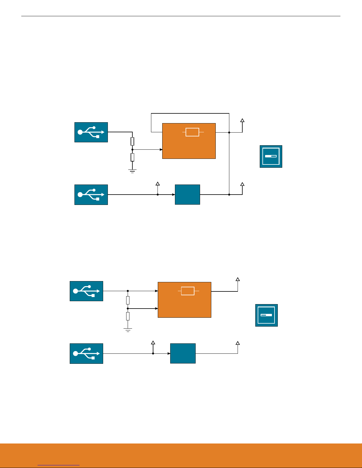
3.2 Power Supply
The EFM8 on the kit can be bus-powered, using its internal 5V-to-3.3 V regulator to provide power to itself and the VMCU net, or the
EFM8 can be self-powered with its internal regulator disabled. In self-powered mode, the EFM8 and the VMCU net are powered by an
on-board low-dropout regulator. Configuring the kit is done using the slide switch marked "Power Source" located in the lower right
corner of the board.
3.2.1 Self-Powered Mode
When the "Power Source" slide switch is in the "DBG USB" position, the EFM8 is connected in self-powered mode with its internal
regulator disabled. In this configuration, the EFM8 and the VMCU net are powered by an on-board regulator, which draws power from
the USB Micro-B debugging connector. The low-dropout regulator has a total output current capacity of 300 mA, in which some is being
used to power the on-board debugger through the 3V3 net.
Figure 3.2. Self-powered Mode
3.2.2 Bus-Powered Mode
When the "Power Source" slide switch is in the "EFM8 USB" position, the EFM8 is connected in bus-powered mode. In this configuration, the EFM8 and the VMCU net are powered by the EFM8UB3's internal 5V-to-3.3 V regulator. The input of the internal regulator
(VREGIN) is connected to the VBUS line of the USB Micro-B connector that is connected to the EFM8's USB peripheral.
Figure 3.3. Bus-powered Mode
silabs.com | Building a more connected world. Rev. 1.0 | 6
Page 7

USB Micro-B
Connector
LDO
VDDVREGIN
P2.1/VBUS
VMCU
D+
D-
VBUS
D-
D+
Bus-powered configuration shown
(switch in EFM8 USB position).
Power Source
EFM8
USB
EFM8UB3
EFM8 USB
User Buttons
& RGB LED
EXP11_LED_RED
EXP7_LED_GREEN
EXP9_LED_BLUE
BUTTON0
[PCA0_CEX2] P1.6
[PCA0_CEX1] P1.4
[PCA0_CEX0] P1.5
P0.2
P0.3
BUTTON1
EFM8UB3
UG308: Thunderboard EFM8UB3 User's Guide
Hardware
3.3 Universal Serial Bus
The Thunderboard EFM8UB3 board is equipped with a USB Micro-B connector interfacing with the EFM8's USB peripheral. The figure
below shows how the USB lines are connected to the MCU. Note that the figure shows the bus-powered configuration, applicable when
the "Power Source" slide switch is in the "EFM8 USB" position. When the switch is in the "DBG USB" position, VREGIN is disconnected
from the VBUS-line and VDD is shorted to VREGIN. For more information, see Section 3.2 Power Supply.
Figure 3.4. Universal Serial Bus
3.4 Push Buttons and RGB LED
The kit has two user push buttons marked BTN0 and BTN1. They are connected directly to the EFM8 and are debounced by RC filters
with a time constant of 1 ms. The buttons are connected to pins P0.2 and P0.3.
The kit also features an RGB LED placed between the two push buttons that is controlled by GPIO pins on the EFM8. The LEDs are
connected in an active-low configuration, and each color can be PWM controlled using the EFM8's Programmable Counter Array
(PCA0) peripheral to generate a wide variety of colors.
Figure 3.5. Buttons and LEDs
silabs.com | Building a more connected world. Rev. 1.0 | 7
Page 8

Mini Simplicity
Connector
RSTb/C2CK
C2D/P2.0
P0.4 [UART1_TX]
P0.5 [UART1_RX]
On-Board
J-Link
Debugger
EXP12_UART_TX
EXP14_UART_RX
EFM8_C2CK
EFM8_C2D
Host
PC
USB
EFM8UB3
UG308: Thunderboard EFM8UB3 User's Guide
Hardware
3.5 On-board Debugger
The Thunderboard EFM8UB3 contains a microcontroller separate from the EFM8 Universal Bee that provides the user with a on-board
J-Link debugger through the USB micro-B debugging port. This microcontroller is referred to as the "On-board Debugger", and is not
programmable by the user.
In addition to providing code download and debug features, the on-board debugger also presents a virtual COM port for general purpose application serial data transfer.
Figure 3.6 On-Board Debugger Connections on page 8 shows the connections between the target EFM8 device and the on-board
debugger. The figure also shows the presence of the Mini Simplicity Connector, and how this is connected to the same I/O pins. Please
refer to section 4. Debugging and section 5. Kit Configuration and Upgrades for more details on debugging.
Figure 3.6. On-Board Debugger Connections
3.6 EFM8 Reset
The EFM8 MCU can be reset by a few different sources:
• A user pressing the RESET button.
• The on-board debugger pulling the EFM8 RSTb pin low.
• An external debugger pulling the EFM8 RSTb pin low.
In addition to the reset sources mentioned above, the debugger will also issue a reset to the EFM8 when starting up. This means that
removing power to the debugger (unplugging the USB Micro-B cable) will not generate a reset, but plugging the cable back in will cause
a reset as the debugger starts up.
silabs.com | Building a more connected world. Rev. 1.0 | 8
Page 9

Breakout Pads
Hirose FH12-6S-0.5SH(55)
EXP2 - VMCU
EXP4 - SPI_MOSI - P1.0
EXP18 - 5V
EXP20 - 3V3
EXP6 - SPI_MISO - P0.7
EXP8 - SPI_SCLK - P0.6
EXP10 - SPI_CS - P1.1
EXP12 - UART_TX - P0.4
EXP14 - UART_RX - P0.5
EXP16 - I2C_SDA - P1.2
GND - EXP1
P0.0 - UART_CTS - EXP3
P0.1 - UART_RTS - EXP5
P1.4 - EXP7
P1.5 - EXP9
P1.6 - EXP11
P2.1 - EXP13
P1.3 - I2C_SCL - EXP15
BOARD_ID_SCL - EXP17
BOARD_ID_SDA - EXP19
P0.3 - BUTTON1
P0.2 - BUTTON0
C2CK / RSTb
C2D - P2.0
DBG USB
Micro-B
Connector
EFM8 USB
Micro-B
Connector
Mini Simplicity
Connector
Top Side
Flat Flexible Cable Connector
(on reverse side)
VMCU
SENSOR_OUT
GND
I2C_SDA
I2C_SCL
SENSOR_TAMPER
Mini Simplicity
Connector
2 1
VMCU
RST
P0.4 - VCOM_TX
P2.0 - C2D
NC
GND
VCOM_RX - P0.5
Not in use by EFM8
C2CK - RSTb/C2CK
NC
Breakout Pads
UG308: Thunderboard EFM8UB3 User's Guide
Hardware
3.7 Connectors
Featured on the Thunderboard EFM8UB3 is a Mini Simplicity connector, two USB Micro-B connectors, a ribbon connector, and 24
breakout pads. Of the breakout pads, 20 follow the Silicon Labs EXP header pinout that provides a fixed feature set across Silicon Labs
starter kits.
The placement and pinout of the connectors can be seen in the figure below. See the following sub chapters for additional information
on the connectors.
Figure 3.7. Thunderboard EFM8UB3 Connectors
silabs.com | Building a more connected world. Rev. 1.0 | 9
Page 10

UG308: Thunderboard EFM8UB3 User's Guide
Hardware
3.7.1 Breakout Pads
The board provides access to every I/O pin of the EFM8 through 24 breakout pads. Twelve of these are located along the left side of
the board while the remaining twelve are located on the right side of the board. The breakout pads contain a number of I/O pins that
can be used with most of the EFM8 Universal Bee's features. Additionally, the VMCU (EFM8 power rail), 3.3V (debug LDO regulator
output), and 5V power rails are also exported.
20 of the breakout pads are pinned out similar to the EXP header found on Silicon Labs Starter Kits, which ensures that commonly
used peripherals such as SPI, UART and I2C buses are available on fixed locations. The rest of the pins are used for general purpose
IO. This allows the definition of expansion boards that can can be used in conjunction with a number of different Silicon Labs starter
kits.
The pin-routing on the EFM8 is very flexible, so most peripherals can be routed to any pin. However, some pins are shared between the
breakout pads and other functions on the Thunderboard EFM8UB3. The table below shows an overview of the breakout pads and functionality that is shared with the kit.
Note: The breakout tab labeled P2.1 in the silkscreen (number 9 on the left side) is connected to a resistor divider on the EFM8 USB
VBUS line. Voltages above VMCU may appear on this pad.
Table 3.1. Breakout Pads Pinout
Number EFM8 Connection EXP Header Pin Shared Feature on Kit Peripheral Mapping
Left Side Breakout Pads (top to bottom)
1 P0.2 - Button
2 P0.3 - Button
3 GND EXP1 - Ground Ground
4 P0.0 EXP3 SENSOR_OUT
5 P0.1 EXP5 SENSOR_TAMPER
6 P1.4 EXP7 LED PCA0_CEX0
7 P1.5 EXP9 LED PCA0_CEX1
8 P1.6 EXP11 LED PCA0_CEX2
1
9
P2.1 / VBUS EXP13 Connected to EFM8 USB 5V through resistor divider
10 P1.3 EXP15 - I2C_SCL SENSOR_SCL SMBUS0_SCL
11 NC EXP17 - Connected to Board Controller for identification of add-on boards
12 NC EXP19 - Connected to Board Controller for identification of add-on boards
Right Side Breakout Pads (top to bottom)
1 C2D / P2.0 - C2D
2 RSTb / C2CK - C2CK / RST
3 VDD EXP2 - VMCU EFM8 voltage domain, included in AEM measurements
4 P1.0 EXP4 - SPI_MOSI SPI0_MOSI
5 P0.7 EXP6 - SPI_MISO SPI0_MISO
6 P0.6 EXP8 - SPI_SCLK SPI0_SCK
7 P1.1 EXP10 - SPI_CS SPI0_NSS
8 P0.4 EXP12 - UART_TX Virtual COM Port UART1_TX0
9 P0.5 EXP14 - UART_RX Virtual COM Port UART1_RX0
10 P1.2 EXP16 - I2C_SDA SENSOR_SDA SMBUS0_SDA
silabs.com | Building a more connected world. Rev. 1.0 | 10
Page 11

UG308: Thunderboard EFM8UB3 User's Guide
Hardware
Number EFM8 Connection EXP Header Pin Shared Feature on Kit Peripheral Mapping
11 NC EXP18 - 5V Connected to Board Controller USB voltage
12
1 Voltages above VMCU may appear on this pad.
2 VDD on the EFM8 is only connected to this pad if the "Power Source" switch is in the "DBG USB" position, and the debug USB
cable is inserted.
3.7.2 Mini Simplicity Connector
The Mini Simplicity connector that can be soldered in on the Thunderboard EFM8UB3 allows the use of an external debugger such as a
Silicon Labs Wireless Starter Kit (WSTK) with the board. In addition to providing the 2-Wire (C2) debug interface and virtual COM port
functionality, the WSTK can also support Advanced Energy Monitoring (AEM). The pinout is described in section 3.7.2 Mini Simplicity
Connector, and the signal names are referenced from the EFM8.
Note: The 10 pin, 1.27 mm pitch Mini Simplicity connector is not provided in the kit and needs to be soldered in by the user.
VDD
2
EXP20 - 3V3 Board controller supply voltage
Table 3.2. Mini Simplicity Connector Pin Descriptions
Pin number Connection Function Description
1 VMCU VAEM Target voltage on the debugged application. Supplied and monitored
by the AEM when power selection switch is in the "AEM" position.
2 GND GND Ground
3 NC NC Not connected
4 P0.5 VCOM_RX Virtual COM Rx
5 P0.4 VCOM_TX Virtual COM Tx
6 NC NC Not connected
7 C2D/P2.0 C2D Serial Wire Data
8 RSTb/C2CK RSTb/C2CK Serial Wire Clock
9 NC NC Not connected
10 NC NC Not connected
3.7.3 EFM8 USB Micro-B Connector
The EFM8 USB port is connected to the Universal Serial Bus (USB0) peripheral on the EFM8. More information is available in section
3.3 Universal Serial Bus.
3.7.4 Debug USB Micro-B Connector
The debug USB port can be used for uploading code, debugging, and as a Virtual COM port. More information is available in section
4. Debugging.
silabs.com | Building a more connected world. Rev. 1.0 | 11
Page 12

UG308: Thunderboard EFM8UB3 User's Guide
Hardware
3.7.5 Flat Flexible Cable Connector
A small, 6-position connector with 0.50 mm pitch for flat flexible cables (FFC) can be found on the secondary side of the board. The
connector (P/N: FH12-6S-0.5SH(55)) allows connections of external Silicon Labs "postage-stamp" (PS) sized evaluation boards to the
kit. Some examples of such boards are the Si7201-B01V-EB Switch PS Board, the Si7210-B00V-EB I2C PS Board, and the Si7211B00V-EB Analog PS Board.
The pinout of the FFC connector is described in the table below.
Table 3.3. Flat Flexible Cable Connector Pin Descriptions
Pin number Connection Function Description
1 P1.3 I2C_SCL The I2C SCL line is pulled up to VMCU with a 4.7 kΩ resistor.
2 P0.1 TAMPER General purpose input/output.
3 P1.2 I2C_SDA The I2C SDA line is pulled up to VMCU with a 4.7 kΩ resistor.
4 GND GND Ground.
5 P0.0 CS/Analog Chip select or analog output.
6 VMCU VMCU EFM8 voltage domain.
silabs.com | Building a more connected world. Rev. 1.0 | 12
Page 13

UG308: Thunderboard EFM8UB3 User's Guide
Debugging
4. Debugging
The Thunderboard EFM8UB3 contains an on-board fully functional SEGGER J-Link Debugger that interfaces to the target EFM8 using
the Silicon Labs 2-Wire (C2) debug interface. The debugger allows the user to download code and debug applications running in the
target EFM8. Additionally, it also provides a virtual COM port (VCOM) to the host computer that is directly connected to the target device's serial port, for general purpose communication between the running application and the host computer.
An external Silicon Labs debugger can also be used with the board by connecting it to the Mini Simplicity connector. This allows advanced debugging features as described in section 4.3 Mini Simplicity Connector. A Silicon Labs Starter Kit (STK) is a good example of
a debugger that can be used with the Thunderboard EFM8UB3 when connected through a debug adapter.
Note: When using an external debugger, the "Power Source" slide switch must be placed in the "DBG USB" position, and the debug
USB cable must be removed to ensure correct operation.
Figure 4.1 Thunderboard EFM8UB3 Debugging Possibilities on page 13 shows the possible debug options.
Figure 4.1. Thunderboard EFM8UB3 Debugging Possibilities
4.1 On-board Debugger Considerations
The on-board debugger is a SEGGER J-Link debugger running on an EFM32 Giant Gecko. The debugger is connected to the C2 and
VCOM pins of the target EFM8 through a level shift and isolation circuit. When the debug USB cable is inserted, the on-board debugger
is automatically active and takes control of the C2 and VCOM interfaces. This means that serial wire debug and communication will not
work with an external STK connected through the Mini Simplicity connector at the same time.
When the debug USB cable is connected, the target EFM8 voltage domain (VMCU) is used to power parts of the level shift and isolation circuit. Furthermore, depending on the "Power Source" slide switch position, the debugger itself may also be powered from the
VMCU rail. These considerations should be taken into account when trying to measure the EFM8 current consumption on the kit while
using the on-board debugger.
When the debug USB cable is disconnected, the on-board debugger is powered down and the level shift and isolation circuit is put in a
partially powered down state, minimizing both leakage current and quiescent current from the target EFM8 voltage domain (VMCU).
This means that high performance power measurements of the EFM8 with either Advanced Energy Monitoring or other external hardware should be obtained with the debug USB cable disconnected.
silabs.com | Building a more connected world. Rev. 1.0 | 13
Page 14

UG308: Thunderboard EFM8UB3 User's Guide
Debugging
4.2 Virtual COM Port
The virtual COM port is a connection to a UART of the target EFM8, and allows serial data to be sent and received from the device. The
on-board debugger presents this as a virtual COM port on the host computer that shows up when the USB cable is inserted. Alternatively, the VCOM port can also be used through the Mini Simplicity Connector with an external WSTK.
Data is transferred between the host computer and the debugger through the USB connection, which emulates a serial port using the
USB Communication Device Class (CDC). From the debugger, the data is passed on to the target device through a physical UART
connection.
The serial format is 115200 bps, 8 bits, no parity, and 1 stop bit.
Using the VCOM port through the Mini Simplicity Connector with an external WSTK works in a similar way, but requires that the onboard debugger is unplugged. The board controller on the WSTK then makes the data available over USB (CDC) or an IP socket.
Note: Changing the baud rate for the COM port on the PC side does not influence the UART baud rate between the debugger and the
target device.
4.3 Mini Simplicity Connector
The Mini Simplicity connector is a 10-pin 1.27 mm pitch connector that gives access to advanced debugging features using an external
debugger. Debugging with an external debugger such as a Silicon Labs Starter Kit (STK) or Wireless Starter Kit (WSTK) allows:
• Debugging of the target device through the C2 interface
• Communication using the VCOM port
• Advanced Energy Monitor
Please note that the Mini Simplicity Connector cannot be used at the same time as the on-board debugger is active (debug USB cable
is plugged in). The "Power Source" slide switch must furthermore be placed in the "DBG USB" position, as the Mini Simplicity connector
injects a voltage into the target EFM8 voltage domain. For information on how to correctly connect to the kit, see Figure 4.1 Thunder-
board EFM8UB3 Debugging Possibilities on page 13. The recommended way to power the board when using the Mini Simplicity Con-
nector is to use the AEM voltage supply of the STK or WSTK. Power-cycling of the board, if necessary, can easily be done by flipping
the power switch on the WSTK to "BAT" and back to "AEM".
silabs.com | Building a more connected world. Rev. 1.0 | 14
Page 15

UG308: Thunderboard EFM8UB3 User's Guide
Kit Configuration and Upgrades
5. Kit Configuration and Upgrades
The kit configuration dialog in Simplicity Studio allows you to change the J-Link adapter debug mode, upgrade its firmware, and change
other configuration settings. To download Simplicity Studio, go to http://www.silabs.com/simplicity.
In the main window of the Simplicity Studio's Launcher perspective, the debug mode and firmware version of the selected J-Link adapter is shown. Click the [Change] link next to any of them to open the kit configuration dialog.
Figure 5.1. Simplicity Studio Kit Information
5.1 Firmware Upgrades
Upgrading the kit firmware is done through Simplicity Studio. Simplicity Studio will automatically check for new updates on startup.
You can also use the kit configuration dialog for manual upgrades. Click the [Browse] button in the [Update Adapter] section to select
the correct file ending in .emz. Then, click the [Install Package] button.
silabs.com | Building a more connected world. Rev. 1.0 | 15
Figure 5.2. Kit Configuration Dialog
Page 16

UG308: Thunderboard EFM8UB3 User's Guide
Schematics, Assembly Drawings and BOM
6. Schematics, Assembly Drawings and BOM
Schematics, assembly drawings and bill of materials (BOM) are available through Simplicity Studio when the kit documentation package has been installed.
silabs.com | Building a more connected world. Rev. 1.0 | 16
Page 17

SLTB005A
Thunderboard EFM8UB3
124802042
20-09-17
A00
UG308: Thunderboard EFM8UB3 User's Guide
Kit Revision History and Errata
7. Kit Revision History and Errata
7.1 Revision History
The kit revision can be found printed on the box label of the kit, as outlined in the figure below. The kit revision history is summarised in
Table 7.1 Kit Revision History on page 17.
Figure 7.1. Revision Info
Table 7.1. Kit Revision History
Kit Revision Released Description
A00 2017-09-20 Initial kit revision.
7.2 Errata
There are no known errata at present.
silabs.com | Building a more connected world. Rev. 1.0 | 17
Page 18

UG308: Thunderboard EFM8UB3 User's Guide
Board Revision History and Errata
8. Board Revision History and Errata
8.1 Revision History
The board revision can be found laser printed on the board, and the board revision history is summarised in Table 8.1 Board Revision
History on page 18.
Table 8.1. Board Revision History
Revision Released Description
A02 2017-09-19 Initial production version.
8.2 Errata
There are no known errata at present.
silabs.com | Building a more connected world. Rev. 1.0 | 18
Page 19

9. Document Revision History
Revision 1.0
December, 2017
• Initial document release.
UG308: Thunderboard EFM8UB3 User's Guide
Document Revision History
silabs.com | Building a more connected world. Rev. 1.0 | 19
Page 20

Simplicity Studio
One-click access to MCU and
wireless tools, documentation,
software, source code libraries &
more. Available for Windows,
Mac and Linux!
IoT Portfolio
www.silabs.com/IoT
Disclaimer
Silicon Labs intends to provide customers with the latest, accurate, and in-depth documentation of all peripherals and modules available for system and software implementers using or
intending to use the Silicon Labs products. Characterization data, available modules and peripherals, memory sizes and memory addresses refer to each specific device, and "Typical"
parameters provided can and do vary in different applications. Application examples described herein are for illustrative purposes only. Silicon Labs reserves the right to make changes
without further notice and limitation to product information, specifications, and descriptions herein, and does not give warranties as to the accuracy or completeness of the included
information. Silicon Labs shall have no liability for the consequences of use of the information supplied herein. This document does not imply or express copyright licenses granted
hereunder to design or fabricate any integrated circuits. The products are not designed or authorized to be used within any Life Support System without the specific written consent of
Silicon Labs. A "Life Support System" is any product or system intended to support or sustain life and/or health, which, if it fails, can be reasonably expected to result in significant personal
injury or death. Silicon Labs products are not designed or authorized for military applications. Silicon Labs products shall under no circumstances be used in weapons of mass
destruction including (but not limited to) nuclear, biological or chemical weapons, or missiles capable of delivering such weapons.
Trademark Information
Silicon Laboratories Inc.® , Silicon Laboratories®, Silicon Labs®, SiLabs® and the Silicon Labs logo®, Bluegiga®, Bluegiga Logo®, Clockbuilder®, CMEMS®, DSPLL®, EFM®, EFM32®,
EFR, Ember®, Energy Micro, Energy Micro logo and combinations thereof, "the world’s most energy friendly microcontrollers", Ember®, EZLink®, EZRadio®, EZRadioPRO®,
Gecko®, ISOmodem®, Micrium, Precision32®, ProSLIC®, Simplicity Studio®, SiPHY®, Telegesis, the Telegesis Logo®, USBXpress®, Zentri and others are trademarks or registered
trademarks of Silicon Labs. ARM, CORTEX, Cortex-M3 and THUMB are trademarks or registered trademarks of ARM Holdings. Keil is a registered trademark of ARM Limited. All
other products or brand names mentioned herein are trademarks of their respective holders.
Silicon Laboratories Inc.
400 West Cesar Chavez
Austin, TX 78701
USA
SW/HW
www.silabs.com/simplicity
Quality
www.silabs.com/quality
Support and Community
community.silabs.com
http://www.silabs.com
 Loading...