

Silicon Laboratories SLWRB4150A User Manual
UG178: EFR32MG 2400/868 MHz 13 dBm
Dual Band Radio Board
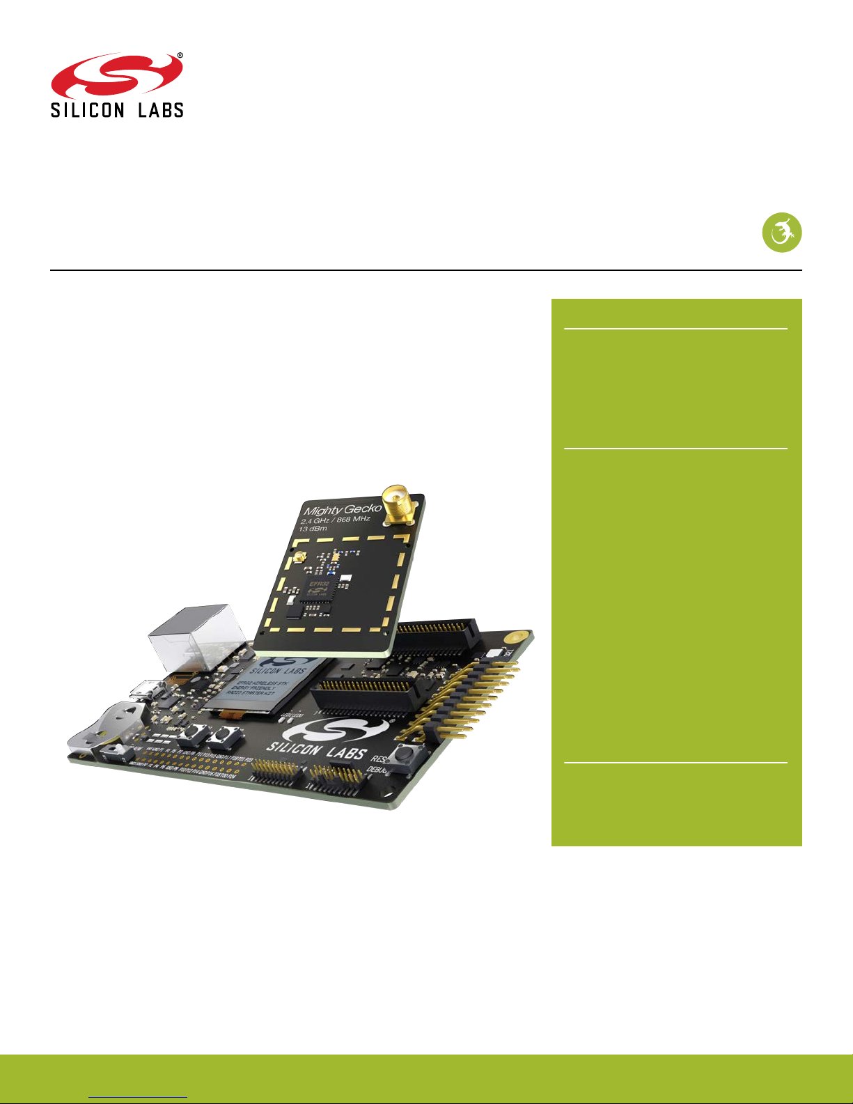
The SLWRB4150A Radio Board for the Wireless Starter Kit Mainboard is an excellent starting point to get familiar with the
EFR32™ Mighty Gecko Wireless System-on-Chip
The Wireless Starter Kit Mainboard contains sensors and peripherals demonstrating
some of the Mighty Gecko's many capabilities. These together provide all necessary
tools for developing a Silicon Labs wireless application.
The WSTK Mainboard is included with all Silicon Labs Wireless Starter Kits. It is not included when purchasing a single radio board.
.
RADIO BOARD FEATURES
• EFR32 Mighty Gecko Wireless SoC with
256 kB Flash and
(EFR32MG1P233F256GM48)
• Inverted-F PCB antenna (2.4 GHz band)
• SMA connector (868 MHz band)
WSTK MAINBOARD FEATURES
• Ethernet and USB connectivity
•
Advanced Energy Monitor
• Packet Trace Interface support
• SEGGER J-Link on-board debugger
• Debug Multiplexer supporting external
hardware as well as radio board
• Silicon Labs' Si7021 Relative Humidity and
Temperature sensor
• Ultra low power 128x128 pixel Memory
LCD
• User LEDs / Pushbuttons
• 20-pin 2.54 mm header for expansion
boards
• Breakout pads for direct access to all radio
I/O pins
• Power sources includes USB, CR2032
coin cell and AA batteries.
32 kB RAM.
silabs.com | Smart. Connected. Energy-friendly
SOFTWARE SUPPORT
• Simplicity Studio™
•
Energy Profiler
• Network Analyzer
. Rev. 1.00

UG178: EFR32MG 2400/868 MHz 13 dBm Dual Band Radio Board
Introduction
1. Introduction
The SLWRB4150A Radio Board is a single EFR32MG 2400/868 MHz 13 dBm radio board for the Wireless Starter Kit Mainboard.
A radio board and a mainboard used together makes a complete development platform for Silicon Labs EFR32 Mighty Gecko Wireless
System-on-Chips.
The Wireless Starter Kit Mainboard features an on-board J-Link debugger, an Advanced Energy Monitor for real-time current and voltage monitoring, a virtual COM port interface, and access to the Packet Trace Interface (PTI).
All debug functionality, including AEM, VCOM and PTI, can also be used towards an external target instead of the connected radio
board.
To further enhance the WSTK usability, the WSTK Mainboard contains sensors and peripherals demonstrating some of the Wireless
SoC's many capabilities.
The radio board features an EFR32 and the RF interface. Please refer to the Radio Board Reference Manual for detailed specifications
and RF performance figures.
1.1 Kit Contents
The following items are included with the SLWRB4150A:
• 1x BRD4150A EFR32MG 2400/868 MHz 13 dBm Radio Board
• 1x 868 MHz antenna with SMA connector
1.2 Getting Started
Detailed instructions for how to get started can be found on the Silicon Labs web pages:
http://www.silabs.com/start-efr32mg
silabs.com | Smart. Connected. Energy-friendly
. Rev. 1.00 | 1
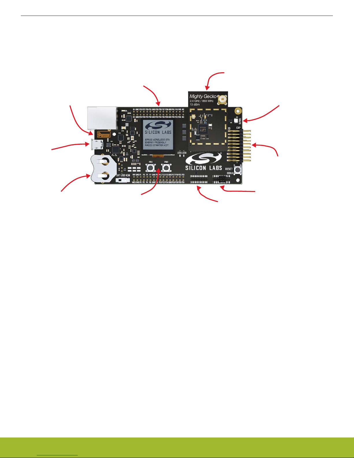
On-board USB and
Ethernet J-Link
Debugger
Radio Board Breakout Pads
Plug-in Radio Board
Si7021 Humidity and
T
emperature Sensor
EXP-header for
expansion
boards
Serial-port, packet trace and Advanced
Energy
Monitoring header
ARM Coresight 19-pin
trace/debug
header
Ultra-low power 128x128
pixel memory LCD,
buttons and LEDs
Battery or
USB
power
USB-serial-port
Packet-trace
Advanced
Energy
Monitoring
UG178: EFR32MG 2400/868 MHz 13 dBm Dual Band Radio Board
Kit Hardware Overview
2. Kit Hardware Overview
A view of the EFR32MG 2400/868 MHz 13 dBm Dual Band Radio Board with a Wireless STK Mainboard is shown below.
Figure 2.1. SLWRB4150A with Wireless STK Mainboard
silabs.com | Smart. Connected. Energy-friendly
. Rev. 1.00 | 2
Debug
USB Mini-B
Connector
UART
RJ-45 Ethernet
Connector
Packet Trace
AEM
Multiplexer
Debug
UART
ETM Trace
Packet Trace
AEM
Debug
UART
Packet Trace
AEM
Simplicity
Connector
Debug
Connector
Board
Controller
OUT
IN
MCU
SMA
Connector
868 MHz RF
2.4 GHz RF
Inverted-F
PCB Antenna
EFR32MG
Wireless SoC
ETM Trace
128 x 128 pixel
Memory LCD
I2C
Si7021
Temperature
& Humidity
Sensor
SPI
8 Mbit
MX25R
Serial Flash
GPI
O
EXP
Header
User Buttons
& LEDs
GPIO
UG178: EFR32MG 2400/868 MHz 13 dBm Dual Band Radio Board
Block Diagram
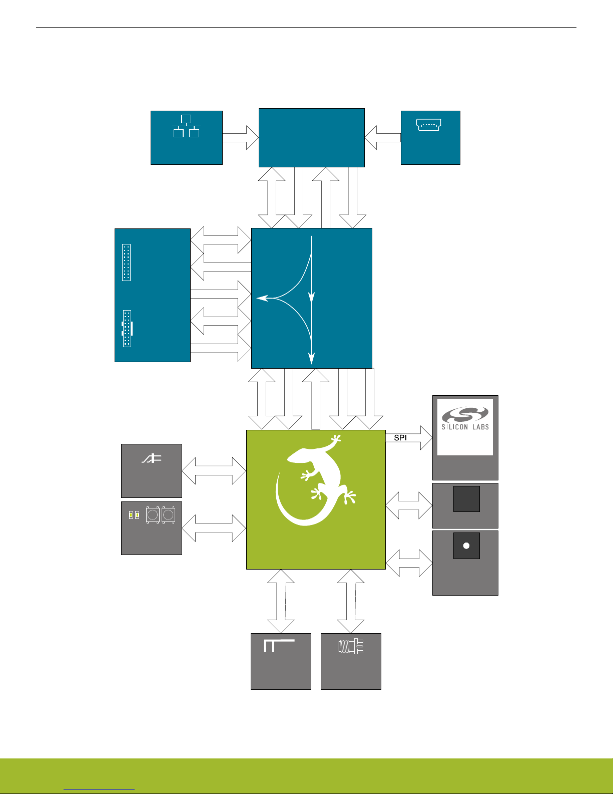
3. Block Diagram
A system overview of the EFR32MG 2400/868 MHz 13 dBm Dual Band Radio Board used together with an Wireless STK Mainboard is
shown in the figure below.
silabs.com | Smart. Connected. Energy-friendly
Figure 3.1. Kit Block Diagram
. Rev. 1.00 | 3
Simplicity
Connector
In/Out Debug
Header
GND
GND
5V
5V
P25
P24
P27
P26
P29
P28
P31
P30
P33
P32
P35
P34
P37
P36
P39
P38
P41
P40
P43
P42
P45
P44
GND
GND
NC
NC
Radio Board
Connectors
Expansion
Header
GND
GND
VMCU
VMCU
P1
P0
P3
P2
P5
P4
P7
P6
P9
P8
P11
P10
P13
P12
P15
P14
P17
P16
P19
P18
P21
P20
GND
GND
P23
P22
VRF
VRF
3V3
3V3
GND
VMCU
P23 / NC
P21 / NC
P19 / NC
P17 / NC
GND
P15 / NC
P13 / PC11 / I2C_SDA
P11 / PA1 / VCOM_RX
P9 / PA0 / VCOM_TX
P7 / PC9
P5 / PC8 / FLASH_SCLK / DISP_SCLK
P3 / PC7 / FLASH_MISO
P1 / PC6 / FLASH_MOSI / DISP_SI
GNDGND
5V5V
NCNC
P45 / NCNC / P44
P43 / NCNC / P42
P41 / NCNC / P40
3V33V3
P39 / NCNC / P38
P37 / PD15 / SENSOR_ENABLENC / P36
P35 / PD15 / DISP_ENABLENC / P34
P33 / PD14 / DISP_SCSLED1 / PF5 / P32
P31 / PD13 / DISP_EXTCOMINNC / P30
P29 / NCDBG_TDO_SWO / PF2 / P28
P27 / NCDBG_TMS_SWDIO / PF1 / P26
P25 / NCDBG_TCK_SWCLK / PF0 / P24
GNDGND
VRF
GND
VMCU
PTI_FRAME / PB13 / P22
PTI_DATA / PB12 / P20
PTI_CLK / PB11 / P18
VCOM_ENABLE / PA5 / P16
GND
FLASH_SCS / PA4 / P14
I2C_SCL / PC10 / P12
DBG_TDI / PF3 / P10
LED0 / PF4 / P8
BTN1 / PF7 / P6
BTN0 / PF6 / P4
VCOM_RTS / PA3 / P2
VCOM_CTS / PA2 / P0
VRF
J101
J102
UG178: EFR32MG 2400/868 MHz 13 dBm Dual Band Radio Board
Connectors
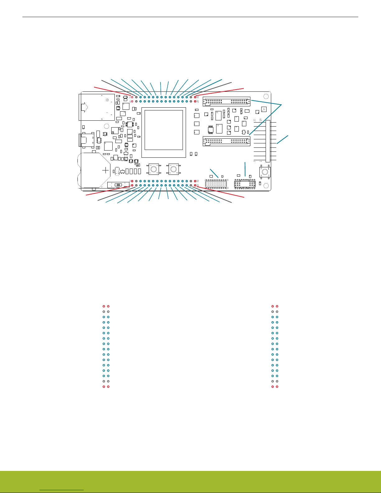
4. Connectors
This chapter gives you an overview of the Wireless Starter Kit Mainboard connectivity. The placement of the connectors can be seen in
the figure below.
4.1 Breakout Pads
of the EFR32's pins are routed from the radio board to breakout pads at the top and bottom edges of the Wireless Starter Kit
Most
Mainboard. A 2.54 mm pitch pin header can be soldered on for easy access to the pins. The figure below shows you how the pins of
the EFR32 maps to the pin numbers printed on the breakout pads. To see the available functions on each, please refer to the
EFR32MG1P233F256GM48 Data Sheet.
silabs.com | Smart. Connected. Energy-friendly
Figure 4.2. Radio Board Pin Mapping on Breakout Pads
Figure 4.1. Mainboard Connector Layout
. Rev. 1.00 | 4

12
4
8
6
10
3
5
9
7
12
13
14
11
1516
17
18
20 19
VMCU
SPI_MOSI / PC6
SPI_MISO / PC7
SPI_CLK / PC8
SPI_CS / PC9
UART_TX / PA0
UART_RX / PA1
I2C_SDA / PC11
5V
3V3
GND
PA2 / GPIO
PA3 / GPIO
PF6 / GPIO
PF7 / GPIO
PF4 / GPIO
PF3 / GPIO
PC10 / I2C_SCL
Board ID SDA
Board ID SCL
Reserved (Board Identification)
EFR32 I/O
Pin
UG178: EFR32MG 2400/868 MHz 13 dBm Dual Band Radio Board
Connectors
4.2 Expansion Header
the right hand side of the board an angled 20-pin expansion header is provided to allow connection of peripherals or plugin boards.
On
The connector contains a number of I/O pins that can be used with most of the EFR32 Mighty Gecko's features. Additionally, the
VMCU, 3V3 and 5V power rails are also exported.
The connector follows a standard which ensures that commonly used peripherals such as an SPI, a UART and an I2C bus are available
on fixed locations in the connector. The rest of the pins are used for general purpose IO. This allows the definition of expansion boards
that can plug into a number of different Silicon Labs starter kits.
The figure below shows the pin assignment of the expansion header for the EFR32MG 2400/868 MHz 13 dBm Dual Band Radio Board.
Because of limitations in the number of available GPIO pins, some of the expansion header pins are shared with kit features.
Figure 4.3. Expansion Header
silabs.com | Smart. Connected. Energy-friendly
. Rev. 1.00 | 5
UG178: EFR32MG 2400/868 MHz 13 dBm Dual Band Radio Board
Connectors
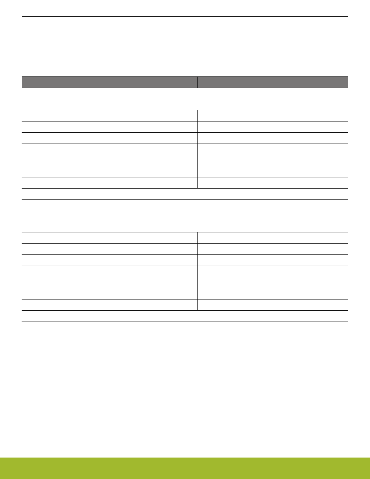
4.2.1 Expansion Header Pin-out
pin-routing on the EFR32 is very flexible, so most peripherals can be routed to any pin. However, many pins are shared between
The
the Expansion Header and other functions on the Wireless STK Mainboard. Table 4.1 Expansion Header Pinout on page 6 includes
an overview of the mainboard features that share pins with the Expansion Header.
Table 4.1. Expansion Header Pinout
Pin Connection EXP Header function Shared feature Peripheral mapping
20 3V3 Board controller supply
18 5V Board USB voltage
16 PC11 I2C_SDA SENSOR_I2C_SDA I2C1_SDA #16
14 PA1 UART_RX VCOM_RX_MISO USART0_RX #0
12 PA0 UART_TX VCOM_TX_MOSI USART0_TX #0
10 PC9 SPI_CS USART1_CS #11
8 PC8 SPI_SCLK FLASH_SCLK, DISP_SCLK USART1_CLK #11
6 PC7 SPI_MISO FLASH_MISO USART1_RX #11
4 PC6 SPI_MOSI FLASH_MOSI, DISP_MOSI USART1_TX #11
2 VMCU EFR32 voltage domain, included in AEM measurements.
19 BOARD_ID_SDA Connected to Board Controller for identification of add-on boards.
17 BOARD_ID_SCL Connected to Board Controller for identification of add-on boards.
15 PC10 I2C_SCL SENSOR_I2C_SCL I2C1_SCL #14
13 PF3 GPIO DBG_TDI
11 PF4 GPIO LED0
9 PF7 GPIO BTN1
7 PF6 GPIO BTN0
5 PA3 GPIO VCOM_RTS_CS USART0_CS #0
3 PA2 GPIO VCOM_CTS_SCLK USART0_CLK #0
1 GND Ground
Note: Pin PF3 is used for DBG_TDI in JTAG mode only. When Serial Wire Debugging is used, PF3 can be used for other purposes.
silabs.com | Smart. Connected. Energy-friendly
. Rev. 1.00 | 6
1 2
4
8
6
10
3
5
9
12
13 14
11
15 16
17 18
20
19
TMS / SWDIO / C2D
TCK / SWCLK /
C2CK
TDO / SWO
TDI / C2Dps
TRACECLK
TRACED0
TRACED1
TRACED2
TRACED3
RESET / C2CKps
GND
NC
NC
GND
GND
GND
7
GND
VTARGET
Cable Detect
NC
UG178: EFR32MG 2400/868 MHz 13 dBm Dual Band Radio Board
Connectors
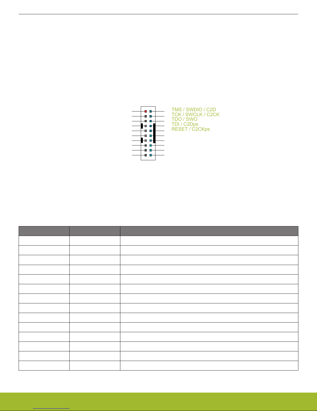
4.3 Debug Connector
Debug Connector serves multiple purposes based on the "debug mode" setting which can be configured in Simplicity Studio. When
The
mode is set to "Debug IN", this connector allows an external debug emulator to be used with the radio board EFR32. When set to "Debug OUT", this connector allows the kit to be used as a debugger towards an external target. When set to "Debug MCU" (default), this
connector is isolated from the debug interface of both the Board Controller and the on-board target device.
Because this connector is automatically switched to support the different operating modes, it is only available when the Board Controller
is powered (J-Link USB cable connected). If debug access to the target device is required when the Board Controller is unpowered, this
should be done by connecting directly to the appropriate breakout pins.
The pinout of the connector follows that of the standard ARM Cortex Debug+ETM 19-pin connector. The pinout is described in detail
below. Even though the connector has support for both JTAG and ETM Trace, it does not necessarily mean that the kit or the on-board
target device supports this.
Figure 4.4. Debug Connector
Note: The
removed from the Cortex Debug+ETM connector. Some cables have a small plug that prevent them from being used when this pin is
present. If this is the case, remove the plug, or use a standard 2x10 1.27 mm straight cable instead.
Pin number(s) Function Description
1 VTARGET Target voltage on the debugged application.
2 TMS / SDWIO / C2D JTAG test mode select, Serial Wire data or C2 data
4 TCK / SWCLK / C2CK JTAG test clock, Serial Wire clock or C2 clock
6 TDO/SWO JTAG test data out or Serial Wire Output
8 TDI / C2Dps JTAG test data in, or C2D "pin sharing" function
10 RESET / C2CKps Target device reset, or C2CK "pin sharing" function
12 TRACECLK Not connected
14 TRACED0 Not connected
16 TRACED1 Not connected
pinout matches the pinout of an ARM Cortex Debug+ETM connector, but these are not fully compatible as pin 7 is physically
Table 4.2. Debug Connector Pin Descriptions
18 TRACED2 Not connected
20 TRACED3 Not connected
9 Cable detect Connect to ground
11, 13 NC Not connected
3, 5, 15, 17, 19 GND Ground
silabs.com | Smart. Connected. Energy-friendly
. Rev. 1.00 | 7
VMCU
1
33V3
5
5V
15
GND
13
GND
11
GND
9
GND
7
GND
17
Board ID
SCL
19
Board ID
SDA
2
V
irtual COM TX / MOSI
4 V
irtual COM RX / MISO
6 Virtual COM CTS / SCLK
8
V
irtual COM RTS / CS
10
Packet T
race 0 Sync
12
Packet T
race 0 Data
14
Packet Trace 0 Clock
16
Packet T
race 1 Sync
18
Packet T
race 1 Data
20
Packet T
race 1 Clock
UG178: EFR32MG 2400/868 MHz 13 dBm Dual Band Radio Board
Connectors
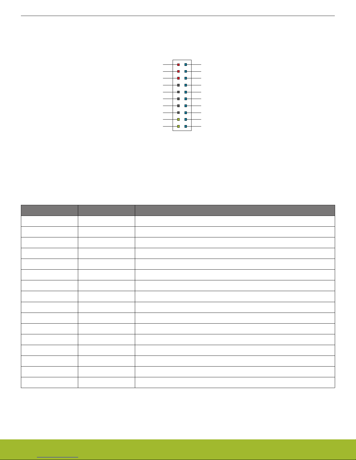
4.4 Simplicity Connector
Simplicity Connector featured on the Wireless Starter Kit Mainboard enables advanced debugging features such as the AEM, the
The
Virtual COM port and the Packet Trace Interface to be used towards an external target. The pinout is illustrated in the figure below.
Figure 4.5. Simplicity Connector
Note: Current
drawn from the VMCU voltage pin is included in the AEM measurements, while the 3V3 and 5V voltage pins are not. To
monitor the current consumption of an external target with the AEM, unplug the WSTK Radio Board from the WSTK Mainboard to avoid
that the Radio Board current consumption is added to the measurements.
Table 4.3. Simplicity Connector Pin Descriptions
Pin number(s) Function Description
1 VMCU 3.3 V power rail, monitored by the AEM
3 3V3 3.3 V power rail
5 5V 5 V power rail
2 VCOM_TX_MOSI Virtual COM Tx/MOSI
4 VCOM_RX_MISO Virtual COM Rx/MISO
6 VCOM_CTS_SCLK Virtual COM CTS/SCLK
8 VCOM_RTS_CS Virtual COM RTS/CS
10 PTI0_SYNC Packet Trace 0 Sync
12 PTI0_DATA Packet Trace 0 Data
14 PTI0_CLK Packet Trace 0 Clock
16 PTI1_SYNC Packet Trace 1 Sync
18 PTI1_DATA Packet Trace 1 Data
20 PTI1_CLK Packet Trace 1 Clock
17 EXT_ID_SCL Board ID SCL
19 EXT_ID_SDA Board ID SDA
7, 9, 11, 13, 15 GND Ground
silabs.com | Smart. Connected. Energy-friendly
. Rev. 1.00 | 8
VMCU
AEM
USB
BAT
USB Mini-B
Connector
Advanced
Energy
Monitor
3 V Lithium Battery
(CR2032 )
BAT
U
SB
AE
M
LDO
EFR32
5 V
3.3 V
UG178: EFR32MG 2400/868 MHz 13 dBm Dual Band Radio Board
Power Supply and Reset
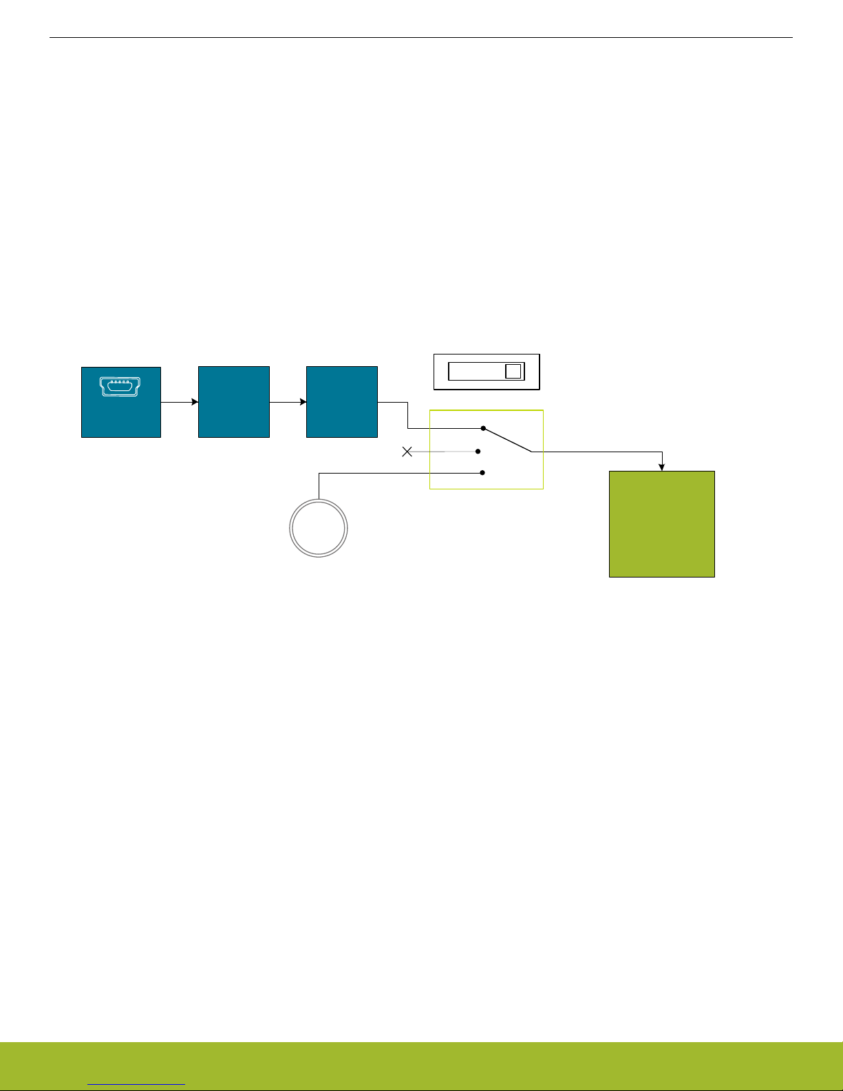
5. Power Supply and Reset
5.1 Radio Board Power Selection
The EFR32 on a Wireless Starter Kit can be powered by one of these sources:
• the debug USB cable;
• a 3V coin cell battery; or
• a USB regulator on the Radio Board (for devices with USB support only).
The power source for the radio board is selected with the slide switch in the lower left corner of the Wireless STK Mainboard. Figure
5.1 Power Switch on page 9 shows how the different power sources can be selected with the slide switch.
Figure 5.1. Power Switch
With the switch in the AEM
again powered from the debug USB cable. The Advanced Energy Monitor is now also connected in series, allowing accurate high
speed current measurements and energy debugging/profiling.
With the switch in the USB position, radio boards with USB-support can be powered by a regulator on the radio board itself. BRD4150A
does not contain an USB regulator, and setting the switch in the USB postition will cause the EFR32 to be unpowered.
Finally, with the switch in the BAT position, a 20 mm coin cell battery in the CR2032 socket can be used to power the device. With the
switch in this position no current measurements are active. This is the recommended switch position when powering the radio board
with an external power source.
Note: The current sourcing capabilities of a coin cell battery might be too low to supply certain wireless applications.
Note: The Advanced Energy Monitor can only measure the current consumption of the EFR32 when the power selection switch is in
the AEM position.
position, a low noise 3.3 V LDO on the WSTK Mainboard is used to power the Radio Board. This LDO is
silabs.com | Smart. Connected. Energy-friendly
. Rev. 1.00 | 9
 Loading...