


Silicon Laboratories SLSTK3701A User Manual

UG287: EFM32 Giant Gecko GG11 Starter
Kit User's Guide
The SLSTK3701A Starter Kit is an excellent starting point to get
familiar with the EFM32™ Giant Gecko GG11 Microcontroller.
The Starter Kit contains sensors and peripherals demonstrating some of the Giant Gecko
GG11's many capabilities. The kit provides all necessary tools for developing an EFM32
Giant Gecko GG11 application.
TARGET DEVICE
• EFM32 Giant Gecko GG11 Microcontroller
(EFM32GG11B820F2048GL192)
• CPU: 32-bit ARM® Cortex-M4® with FPU
• Memory: 2048 kB flash and 512 kB RAM
KIT FEATURES
• USB connectivity
• Advanced Energy Monitor
• SEGGER J-Link on-board debugger
• Debug Multiplexer supporting external
hardware as well as on-board MCU
• Silicon Labs Si7021 Relative Humidity and
Temperature sensor
• User LEDs / Pushbuttons
• Ultra low power 128x128 pixel color
Memory LCD
• Inductive LC sensor
• Silicon Labs Si7210 Hall-Effect Sensor
• Digital Stereo Microphones
• Micro-SD Slot
• 32 Mbit QSPI flash memory
• Ethernet connectivity
• Capacitive Touch Slider
• 20-pin 2.54 mm header for expansion
boards
• Breakout pads for direct access to I/O pins
• Power sources include USB and CR2032
coin cell battery.
silabs.com
| Building a more connected world. Rev. 1.10
SOFTWARE SUPPORT
• Simplicity Studio™
• IAR Embedded Workbench

Table of Contents
1. Introduction ................................4
1.1 Description ...............................4
1.2 Features................................4
1.3 Getting Started .............................4
2. Kit Block Diagram .............................5
3. Kit Hardware Layout ............................6
4. Connectors ................................7
4.1 Breakout Pads .............................7
4.2 Expansion Header ............................9
4.3 Debug Connector (DBG) ..........................11
4.4 Simplicity Connector............................12
5. Power Supply and Reset ..........................13
5.1 MCU Power Selection ...........................13
5.2 Board Controller Power...........................13
5.3 EFM32 Reset ..............................14
6. Peripherals ...............................15
6.1 Push Buttons and RGB LEDs ........................15
6.2 Memory LCD-TFT Display..........................16
6.3 Capacitive Touch Slider ..........................17
6.4 Si7021 Relative Humidity and Temperature Sensor .................17
6.5 Si7210 Hall-Effect Sensor ..........................18
6.6 LC Sensor ...............................18
6.7 Digital Stereo Microphones .........................19
6.8 USB Micro-AB Connector ..........................20
6.9 QSPI Flash Memory ............................21
6.10 Micro-SD Slot .............................21
6.11 10/100Base-TX Ethernet ..........................22
6.12 Virtual COM Port ............................23
7. Advanced Energy Monitor .........................24
7.1 Usage ................................24
7.2 Theory of Operation ............................24
7.3 Secondary AEM Channel ..........................24
7.4 Accuracy and Performance .........................25
8. On-Board Debugger ............................26
silabs.com
| Building a more connected world. Rev. 1.10 | 2

8.1 Debug Modes ..............................27
8.2 Debugging During Battery Operation ......................28
9. Kit Configuration and Upgrades .......................29
9.1 Firmware Upgrades ............................29
10. Schematics, Assembly Drawings and BOM ..................30
11. Kit Revision History and Errata .......................31
11.1 Revision History.............................31
11.2 Errata ................................31
12. Document Revision History ........................32
silabs.com | Building a more connected world. Rev. 1.10 | 3

UG287: EFM32 Giant Gecko GG11 Starter Kit User's Guide
Introduction
1. Introduction
1.1 Description
The SLSTK3701A is an excellent starting point to get familiar with the EFM32 Giant Gecko GG11 Microcontrollers. The kit contains
sensors and peripherals demonstrating some of the EFM32 Giant Gecko GG11's many capabilities. The kit can also serve as a starting
point for application development.
In addition to supporting application development on the starter kit itself, the board is also a fully featured debugger and energy monitoring tool that can be used with external applications.
1.2 Features
• EFM32 Giant Gecko GG11 Microcontroller
• 2048 kB Flash
• 512 kB RAM
• BGA192 package
• Advanced Energy Monitoring system for precise current and voltage tracking
• Integrated Segger J-Link USB debugger/emulator with the possiblity to debug external Silicon Labs devices
• 20 pin expansion header
• Breakout pads for easy access to I/O pins
• Power sources include USB and CR2032 battery
• Silicon Labs Si7021 Relative Humidity and Temperature Sensor
• Silicon Labs Si7210 Hall-Effect sensor
• Ultra low power 128x128 pixel Color Memory-LCD
• Digital stereo MEMS microphones
• USB Micro-AB connector supporting both host and device mode USB applications
• 10/100Base-TX ethernet PHY and RJ-45 jack
• Micro-SD slot supporting SD memory cards and SDIO expansion cards
• 32 Mbit QSPI serial flash supporting execute-in-place (XIP)
• 2 push buttons and 2 RGB LEDs connected to EFM32 for user interaction
• LC tank circuit for inductive proximity sensing of metallic objects
• Backup battery
• 4-segment capacitive touch slider
• Crystals for LFXO and HFXO: 32.768 kHz and 50.000 MHz.
1.3 Getting Started
Detailed instructions for how to get started with your new SLSTK3701A can be found on the Silicon Labs web pages:
http://www.silabs.com/start-efm32gg1
silabs.com | Building a more connected world. Rev. 1.10 | 4
128 x 128 Pixel
Color Memory LCD
SPI
EXP Header
LC Sensor
I2S
LESENSE
GPIO
Board
Controller
USB Mini-B
Connector
DEBUG
UART
Capacitive Touch Slider
CSEN
Ethernet PHY
& Jack
Micro-SD Slot
USB Micro-AB
Connector
Digital Stereo
Microphones
Hall-Effect
Sensor
Si7210
Si7021
Temperature
& Humidity
Sensor
User Buttons
& RGB LEDs
32 Mbit QSPI
Flash Memory
EFM32GG11
MCU
I2C
RMII
SDIO
QSPI
USB
GPIO
UG287: EFM32 Giant Gecko GG11 Starter Kit User's Guide
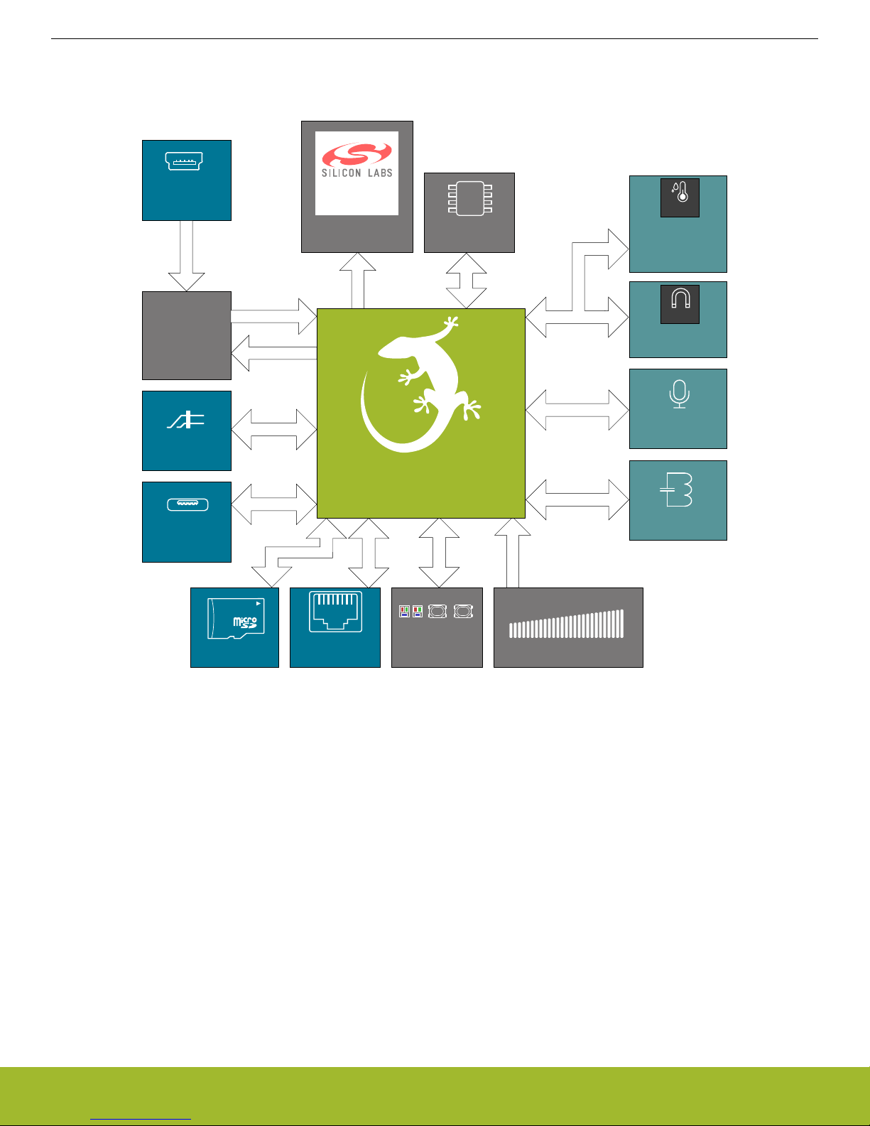
2. Kit Block Diagram
An overview of the EFM32 Giant Gecko GG11 Starter Kit is shown in the figure below.
Kit Block Diagram
Figure 2.1. Kit Block Diagram
silabs.com | Building a more connected world. Rev. 1.10 | 5

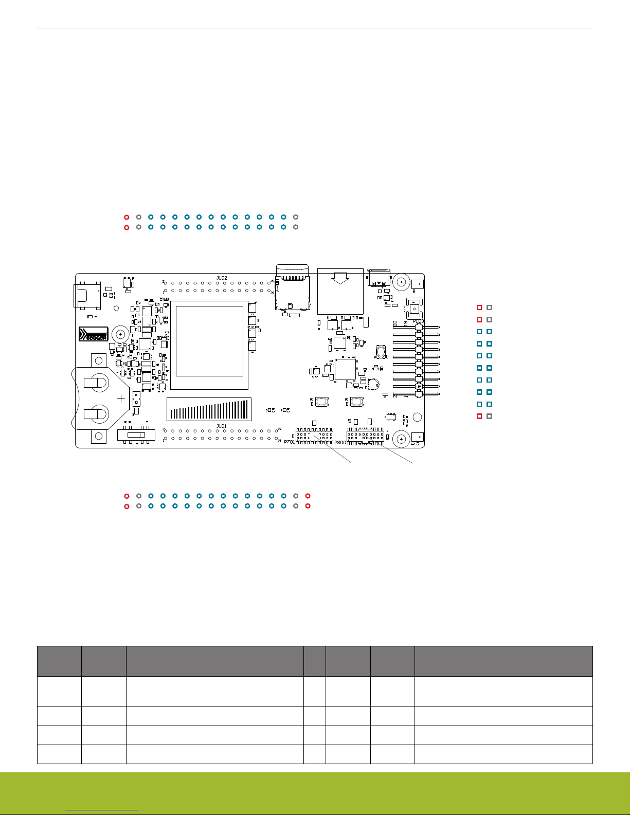
3. Kit Hardware Layout
Debug USB
Connector
CR2032
Battery Holder
128x128 Pixel
Color Memory LCD
Relative Humidity &
Temperature Sensor
EFM32GG11 MCU
Expansion Header
EFM32 Reset Button
Hall-Effect Sensor
User RGB LEDs
User Push Buttons
Power Source Select
Inductive LC Sensor
Micro-SD slot
Ethernet PHY
Capacitive Touch Slider
Digital Microphone (R)
Digital Microphone (L)
EFM32 USB Connector
EFM32 Ethernet Connector
Backup Battery
Simplicity Connector
QSPI Flash Memory
Debug Connector
The layout of the EFM32 Giant Gecko GG11 Starter Kit is shown below.
UG287: EFM32 Giant Gecko GG11 Starter Kit User's Guide
Kit Hardware Layout
Figure 3.1. SLSTK3701A Hardware Layout
silabs.com | Building a more connected world. Rev. 1.10 | 6
GND
VMCU
PE3
PE2
PH6
PH3
GND
PH2
PH1
PH0
PG8
PG7
PG6
PI12
PI11
3V3
GND
VMCU
PD8
PG15
PI9
PI8
GND
PI7
PI6
PI5
PI4
PI3
PI2
PI1
PI0
3V3
J101
J102
GND
5V
PD7
PD6
PD5
PD1
GND
PF13
PF5
PF4
PF2
PF1
PF0
RST
BDEN
GND
5V
PC15
PC14
PC13
PC12
GND
PC11
PC10
PC7
PC6
PA14
PA11
PA10
PA8
PA12
PA13
PC4
PC5
GND
PB11
PB9
PC1
5V
PE10
PE11
PE12
PE13
PE8
PE9
PC0
VMCU
3V3
Board ID SDA
Board ID SCL
EXP Header
Debug
Connector
Simplicity
Connector
UG287: EFM32 Giant Gecko GG11 Starter Kit User's Guide
Connectors
4. Connectors
4.1 Breakout Pads
Most of the EFM32's GPIO pins are available on two pin header rows at the top and bottom edges of the board. These have a standard
2.54 mm pitch, and pin headers can be soldered in if required. In addition to the I/O pins, connections to the different power rails and
ground are also provided. Note that some of the pins are used for kit peripherals or features, and may not be available for a custom
application without trade-offs.
The figure below shows the pinout of these "breakout pads", as well as the pinout of the "Expansion Header" situated on the right-hand
side of the board. The expansion header is further explained in the next section. The breakout pad connections are also printed in silk
screen next to each pin for easy reference.
Figure 4.1. Breakout Pads and Expansion Header
The table below shows the connections of each pin of the breakout pads. They also show which kit peripherals or features are connected to the different pins.
Table 4.1. Bottom Row (J101) Pinout
Pin EFM32
I/O pin
1 VMCU EFM32 voltage domain (measured by
3 GND Ground 4 GND Ground
5 PI0 6 PI11
7 PI1 8 PI12
Shared feature Pin EFM32
2 VMCU EFM32 voltage domain (measured by
AEM)
I/O pin
Shared feature
AEM)
silabs.com | Building a more connected world. Rev. 1.10 | 7
UG287: EFM32 Giant Gecko GG11 Starter Kit User's Guide
Connectors
Pin EFM32
I/O pin
Shared feature Pin EFM32
I/O pin
Shared feature
9 PI2 10 PG6
11 PI3 12 PG7
13 PI4 SENSOR_I2C_SDA 14 PG8
15 PI5 SENSOR_I2C_SCL 16 PH0
17 PI6 18 PH1
19 PI7 20 PH2
21 PI8 22 PH3
23 PI9 24 PH6
25 PG15 ETH_INTERRUPT 26 PE2
27 PD8 BU_VIN 28 PE3
29 GND Ground 30 GND Ground
31 3V3 Board controller supply 32 3V3 Board controller supply
Table 4.2. Top Row (J102) Pinout
Pin EFM32
I/O pin
Shared feature Pin EFM32
I/O pin
Shared feature
1 5V Board USB voltage 2 5V Board USB voltage
3 GND Ground 4 GND Ground
5 PA8 6 BDEN BOD_ENABLE
7 PA10 8 RST DEBUG_RESET
9 PA11 DISP_COM 10 PF0 DEBUG_TCK_SWCLK
11 PA14 DISP_MOSI 12 PF1 DEBUG_TMS_SWDIO
13 PC6 DEBUG_TRACECLK 14 PF2 DEBUG_TDO_SWO
15 PC7 DEBUG_TRACED0 16 PF4 USB_OC_FAULT
17 PC10 18 PF5 DEBUG_TDI / USB_VBUSEN
19 PC11 20 PF13
21 PC12 22 PD1 OPA1_OUT
23 PC13 24 PD5 DEBUG_TRACED3
25 PC14 DISP_CS 26 PD6 OPA1_P
27 PC15 DISP_CLK 28 PD7 OPA1_N
29 GND Ground 30 GND Ground
silabs.com | Building a more connected world. Rev. 1.10 | 8
12
4
8
6
10
3
5
9
7
12
13
14
11
1516
17
18
20 19
VMCU
PE10
PE11
PE12
PE13
PE8
PE9
PC0
5V
3V3
GND
PA12
PA13
PC4
PC5
PB11
PB9
PC1
Board ID SDA
Board ID SCL
Reserved (Board Identification)
TARGET I/O Pin
UG287: EFM32 Giant Gecko GG11 Starter Kit User's Guide
Connectors
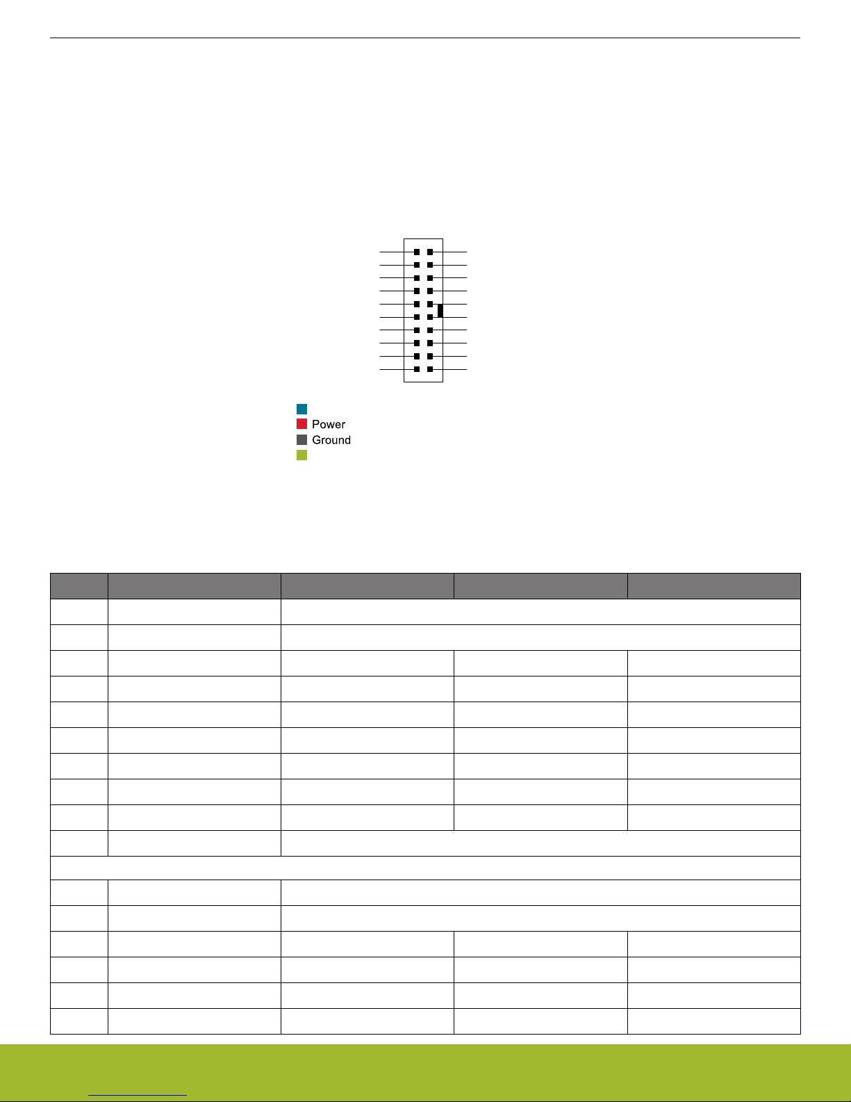
4.2 Expansion Header
On the right hand side of the board an angled 20 pin expansion header is provided to allow connection of peripherals or plugin boards.
The connector contains a number of I/O pins that can be used with most of the EFM32 Giant Gecko GG11's features. Additionally, the
VMCU, 3V3 and 5V power rails are also exported.
The connector follows a standard which ensures that commonly used peripherals such as an SPI, a UART and an I2C bus are available
on fixed locations in the connector. The rest of the pins are used for general purpose I/O. This allows the definition of expansion boards
that can plug into a number of different Silicon Labs starter kits.
The figure below shows the pin assignment of the expansion header for the EFM32 Giant Gecko GG11 Starter Kit. Because of limitations in the number of available GPIO pins, some of the expansion header pins are shared with kit features.
Figure 4.2. Expansion Header
Table 4.3. EXP Header Pinout
Pin Connection EXP Header function Shared feature Peripheral mapping
20 3V3 Board controller supply
18 5V Board controller USB voltage
16 PC0 I2C_SDA CAN0_RX #0 I2C0_SDA #4
14 PE9 UART_RX SDIO_DAT2 #0 USART5_RX #0
12 PE8 UART_TX SDIO_DAT3 #0 USART5_TX #0
10 PE13 SPI_CS SDIO_CLK #0 USART0_CS #0
8 PE12 SPI_SCLK SDIO_CMD #0 USART0_CLK #0
6 PE11 SPI_MISO SDIO_DAT0 #0 USART0_RX #0
4 PE10 SPI_MOSI SDIO_DAT1 #0 USART0_TX #0
2 VMCU EFM32 voltage domain, included in AEM measurements.
19 BOARD_ID_SDA Connected to Board Controller for identification of add-on boards.
17 BOARD_ID_SCL Connected to Board Controller for identification of add-on boards.
15 PC1 I2C_SCL CAN0_TX #0 I2C0_SCL #4
13 PB9 GPIO
11 PB11 DAC_OUT VDAC0_OUT0
9 PC5 I2C_SCL SDIO_WP #1 I2C1_SCL #0
silabs.com | Building a more connected world. Rev. 1.10 | 9

UG287: EFM32 Giant Gecko GG11 Starter Kit User's Guide
Connectors
Pin Connection EXP Header function Shared feature Peripheral mapping
7 PC4 I2C_SDA SDIO_CD #1 I2C1_SDA #0
5 PA13 CAN_TX PCNT1_S1IN #5 CAN1_TX #5
3 PA12 CAN_RX PCNT1_S0IN #5 CAN1_RX #5
1 GND Ground
silabs.com | Building a more connected world. Rev. 1.10 | 10