

Silicon Laboratories Si86xxT-EVB User Manual

UG130: Si86xxT-EVB User's Guide
The Si864xxT devices, the latest addition to the Si86xx isolator family, are 4-channel
CMOS-based galvanic digital isolators surge rated at 10 kV. Operating up to 150 Mbps,
they are available in wide body 16-pin SOIC packages and designed for the stringent
isolation needs of the industrial, commercial, and automotive markets. Various channel
configurations dictating the number of reverse channels and default output states are
also available per the Si86xx data sheet’s ordering guide.
The Si864xxT-EVB allows designers to quickly evaluate the Si8642ET’s capabilities
and functionality, either by driving inputs to logic low via shunts, or injecting signals to
the header pins via single wires or a 2x6 ribbon cable (not included).
For more information on our Si86xxT isolators, visit the Silicon Labs website at: http://
www.silabs.com/isolation. The product data sheet and application notes can be refer-
enced to help facilitate designs.
KEY POINTS
• Discusses kit contents and equipment.
•
Describes hardware setup and
demonstration.
• Shows EVB schematic and layout.
• Includes bill of materials and the ordering
guide for Si864xxT-KIT.
silabs.com | Smart. Connected. Energy-friendly. Rev. 0.1

1. Kit Contents
The Si864xxT Evaluation Kit contains the following items:
•
Si864xxT-EVB evaluation board, shown in the figure below.
• Si8642ET-IS, 4-channel (Reverse: 3 and 4), 150 Mbps, 10 kV, Wide Body, Default High I/O.
UG130: Si86xxT-EVB User's Guide
Kit Contents
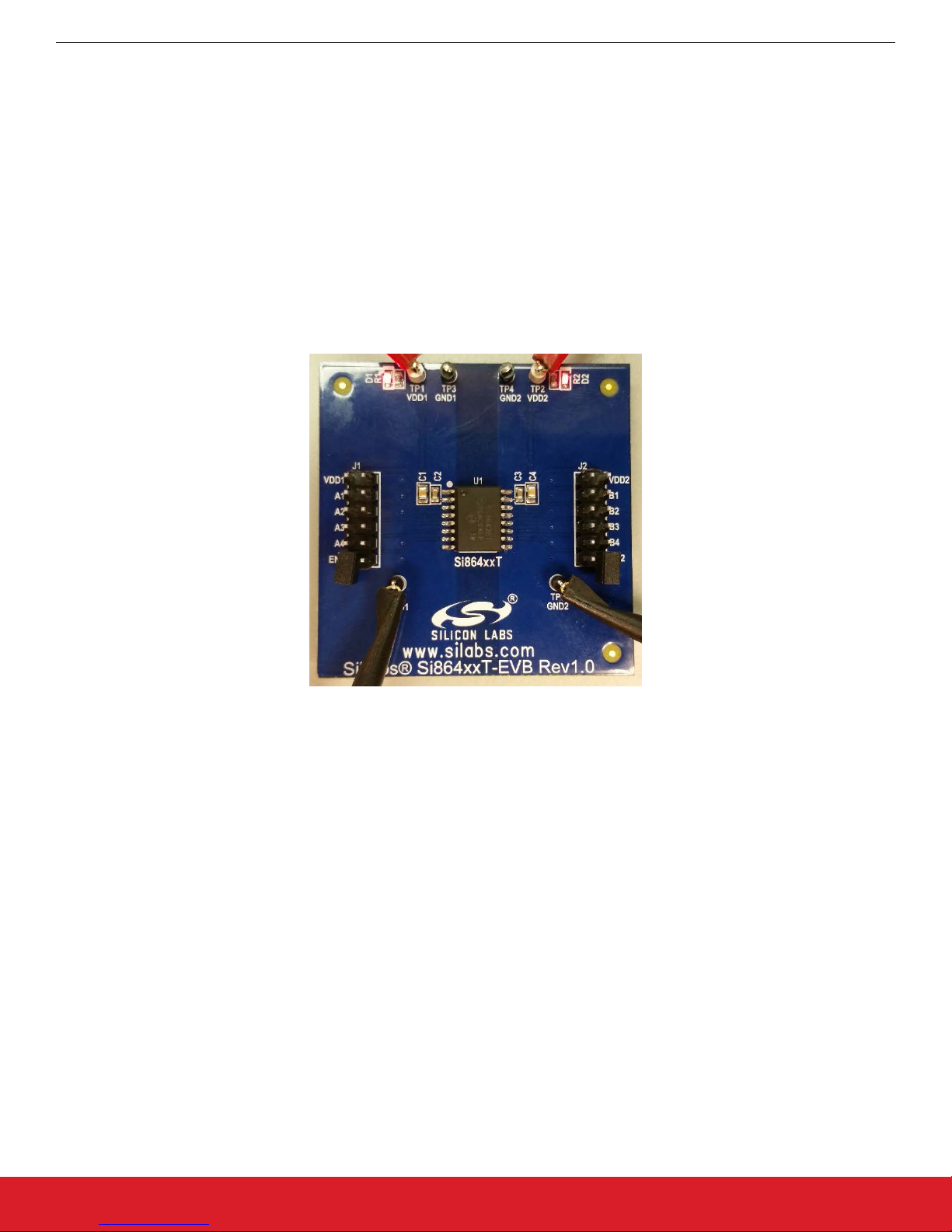
Figure 1.1. Si86xxT-EVB
silabs.com | Smart. Connected. Energy-friendly. Rev. 0.1 | 1

UG130: Si86xxT-EVB User's Guide
Required Equipment
2. Required Equipment
The following equipment is required to demonstrate the evaluation board:
•
Two DC Power supplies 2.5–5.5 V, 100 mA.
• (Optionally) Isolated from one another.
• Four banana-to-test-clip cables with clips to supply power to the board.
• Two 2-pin header shunts (included).
• One DMM.
• One DMM Voltage Probe Set.
2.1 Optional Equipment
The following equipment is optional and can be used to demonstrate more of the evaluation board functionalities, including signal propagation statistics:
• One Signal generator.
• Two BNC Coaxial cables.
• One BNC splitter.
• One BNC to test-clip connector.
• One 2-Channel Oscilloscope.
• One 10x Voltage Probe.
silabs.com | Smart. Connected. Energy-friendly. Rev. 0.1 | 2
3. Hardware Setup and Demonstration
3.1 Powering the Supplies
Both sides of the Si8642ET isolator accept supplies between 2.5-5.5 V. See the figure below.
Perform the following steps to set up the Si864xxT-EVB:
• Remove all shunts.
• Power Side-A.
• Clip 5.0 V from the first power supply to TP1 (VDD1) and its GND to TP3 or TP5 (GND1).
• LED, D1, will light up, confirming power is supplied.
• Power Side-B.
• Clip 5.0 V from the second power supply to TP2 (VDD2) and its GND to TP4 or TP6 (GND2).
• LED, D2, will light up, confirming power is supplied.
UG130: Si86xxT-EVB User's Guide
Hardware Setup and Demonstration
Figure 3.1. EVB — Powered Up
3.2 DC Signal Demonstration
3.2.1 Defaults
The
default output signal state of the Si8642ET is a logic High, meaning that with all shunts removed (EN1 and EN2 floating), all digital
inputs (A1, A2, B3, B4) and all digital outputs will (B1, B2, A3, A4) will be at their respective High voltage level. These values can be
measured and confirmed using the DMM.
• Remove all shunts.
• Measure with the DMM that all digital inputs (A1, A2, B3, B4) are logic High.
• Measure with the DMM that all digital outputs (B1, B2, A3, A4) are logic High.
See Figure 3.1 EVB — Powered Up on page 3.
silabs.com | Smart. Connected. Energy-friendly. Rev. 0.1 | 3
UG130: Si86xxT-EVB User's Guide
Hardware Setup and Demonstration
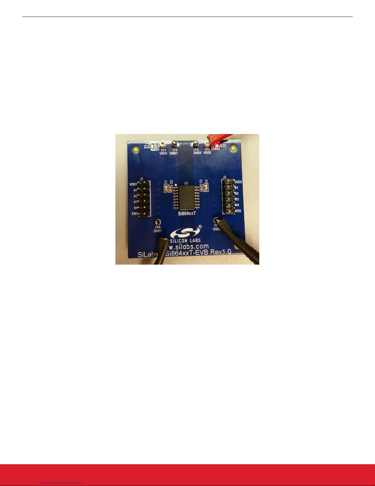
3.2.2 Fail-safes
When power is removed from one side of the isolator, the outputs at the other side of the isolator default to logic High.
A-side
•
• Remove all shunts.
• Remove A-side power supply.
• Measure B-side outputs, B1 and B2 and see that they are logic High.
• Replace A-side power and see B1 and B2 driven to their appropriate states.
• B-side
• Remove all shunts.
• Remove B-side power supply.
• Measure A-side outputs, A3 and A4 and see that they are logic High.
• Replace B-side power and see A3 and A4 drive to their appropriate states.
Figure 3.2. EVB — Failsafe, No VDDA
silabs.com | Smart. Connected. Energy-friendly. Rev. 0.1 | 4
 Loading...