

Page 1
Si4010-Keyfob-AES-DEMO
Si4010 KEY FOB DEMO KIT WITH AES CAPABILITY
U
SER’S GUIDE
1. Purpose
Thank you for your interest in Silicon Laboratories’ Si4010 SoC RF key fob demo kit with AES capability. The
Silicon Laboratories Si4010 key fob demo kit with AES capability contains everything you need to familiarize
yourself with and evaluate the Si4010 RF SoC. The kit has two versions, one for the 434 MHz band and one for the
868 MHz band. The key features of the developme nt pla tform are as fo llows :
The key fob demo board has five push buttons and one LED output, a PCB antenna, and a battery in a plastic
case.
The key fob uses hardware-accelerated 128-bit advanced encryption standard (AES) encryption and rolling
counter for RKE application.
The receiver demo board has a graphic LCD to display received key fob commands.
The provided software pack contains all the d ocum entation and files needed to develop a user application. Th e
kit supports the use of Silicon Laboratories’ Integrated Development Environment (IDE) for software debugging
and the use of the Keil C compiler, assembler, and linker toolchain.
Contains demo applications using API functions and the key fob demo application.
2. Kit Contents
The kit contains the following items:
Qty Part Number Description
4010-DAAKF_434 Si4010 Key Fob Demo Kit with AES Capability 434 MHz
1 4010-DAPB_434 Si4010 Universal Key Fob 434 MHz
1 4313-DACB_ANY Si4313 LCD FSK/OOK Receiver any band
1 MSC-AT50-434 434 MHz Antenna
1 MSC-PLPB_1 Key Fob Plastic Case (translucent grey)
1 CRD2032 CR2032 3 V coin battery
1 MSC-DKSW1 Wireless Development Suite disc
4010-DAAKF_868 Si4010 Key Fob Demo Kit with AES Capability 868 MHz
1 4010-DAPB_868 Si4010 Universal Key Fob 868 MHz
1 4313-DACB_ANY Si4313 LCD FSK/OOK Receiver any band
1 MSC-AT50-868 868 MHz Antenna
1 MSC-PLPB_2 Key Fob Plastic Case (translucent red)
1 CRD2032 CR2032 3 V coin battery
1 MSC-DKSW1 Wireless Development Suite disc
Rev 1.1 4/11 Copyright © 2011 by Silicon Laboratories Si4010-Keyfob-AES-DEMO
Page 2
Si4010-Keyfob-AES-DEMO
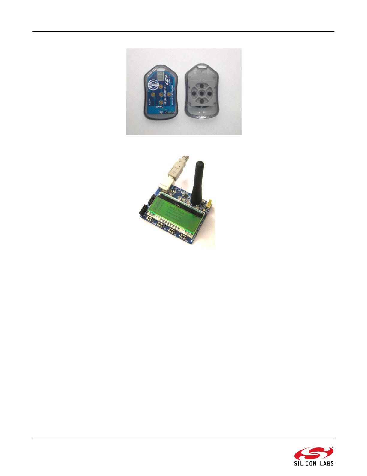
Figure 1. Si4010 Universal Key Fob and Plastic Case (P/N 4010-DAPB 868 and MSC-PLPB_1)
Figure 2. Si4313 LCD FSK/OOK Receiver Any-Band (P/N 4313-DACB ANY) with 434 MHz Antenna
(P/N MSC-AT50-434)
2 Rev 1.1
Page 3
Si4010-Keyfob-AES-DEMO
3. Key Fob Demo with AES Capability
The 4010-DAPB RKE key fob transmitter and the Si4313 FSK receiver are the transmit and receive devices used
in this key fob demo. This transmit/receive pair can be used to evaluate the capabilities of the Si4010 transmitter
and the Si4313 receiver.
3.1. Operation of the Demo
The Si4313 demo receiver board uses the following RF parameters:
9.6 kbps
FSK modulation
433.92 MHz or 868.3 MHz center frequency (menu selectable)
±70 kHz deviation
If any push button is pressed on the key fob, it sends a message to the receiver. The demo uses Silicon Labs'
general EZMacPRO protocol.
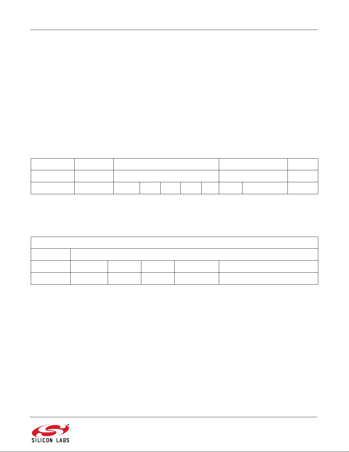
Table 1. General EZMacPRO Extended Packet Configuration Used by Demo Key Fobs
Preamble SynchWord MACHeader MACPayload CRC
Min.13 bytes 2 bytes 5 bytes 0...64 bytes 2 bytes
0xAA...0xAA 0x2DD4 CTRL CID SID DID PL NHDR NWK payload CRC
3.2. Association
To enable the receiver to react to the button presses on the key fob(s), they have to be paired (i.e., the key fob has
to be associated to the receiver by pressing the left and right buttons simultaneously on the key fob).
Table 2. The MAC Payload Field of the “Associate Request from TX only Device” Packet
MACPayload
NHDR NWK Payload
1 byte 1 bytes 1 byte 1 byte 4 byte 4 byte
0x47 0x05 0x01 AES Address Rolling Counter
3.2.1. Meanings of the Different Fields
AES—Defines whether the transmitter is using AES-128 encryption or not. It is set to 0x01; then, the Rolling
counter field of the packets is extended to 16 bytes length (12 dummy bytes are appended) and is encoded by
AES-128. Other fields of the packet are not affected by the encryption.
Address—4 bytes of key fob address. The four byte random number factory burned in the Si4010 is used as
the address.
Rolling Counter—The transmitter increments a 4 byte counter after every packet transmission. This counter is
stored in the MTP memory of the Si4010.
If the receiver accepts the association, it registers the Address, Master Key, and Rolling Counter value of the
requesting key fob.
The Master accepts the association if it is in pairing mode and there is a free slot for a key fob (i.e., if there are
fewer than four key fobs associated to the receiver).
After power up, the Receiver board is in pairing mode automatically. After pairing, it goes to normal packet
reception mode. The Pairing mode can be invoked by pressing the push button, PB3, on the Receiver Board. This
button needs to be pressed before the second and any subsequent pairing. If the PB is pressed for more than one
second, the receiver disassociates all key fobs.
Rev 1.1 3
Page 4
Si4010-Keyfob-AES-DEMO
3.3. Button is Pressed on the Key Fob
If any single button or button combination (except association combination) is pressed on the key fob, then it
transmits a key fob data packet showing the button number in the button field.
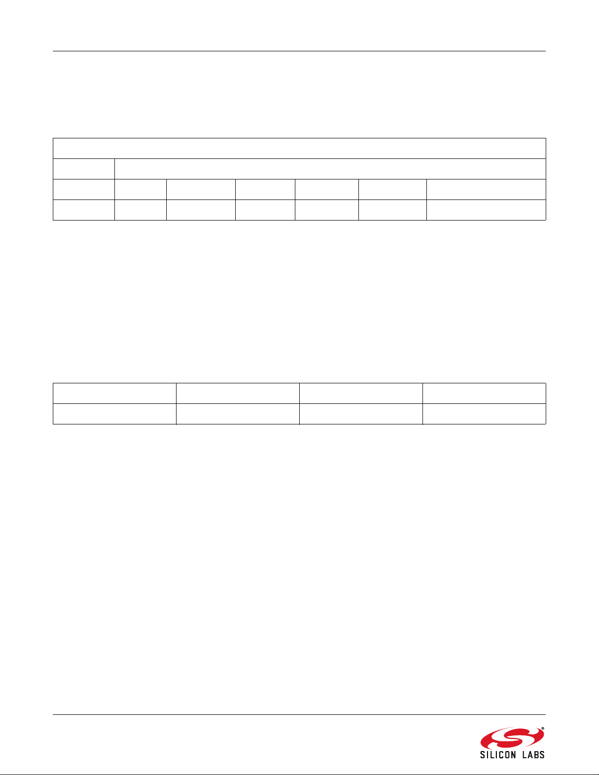
Table 3. The MAC Payload Field of the “Key Fob Data” Packet
MAC Payload
NHDR NWK payload
1byte 1byte 4bytes 1byte 2bytes 1byte 4byte
0x04 AES Address Button TEMP Battery Rolling Counter
3.3.1. Meaning of the Different Fields
AES—Defines whether the transmitter is using AES-128 encryption. It is set to 0x01, then Button, Temp,
Battery, and Rolling counter fields of the packets are extended to 16 bytes length all together and are encoded
by AES-128. Other fields of the packet are not affected by the encryption.
Address—4 bytes of key fob address. The four-byte random number factory burned in the Si4010 is used as
the address.
Button—Each bit of this byte corresponds to the status of a push button on the key fob. If the bit is set, the
given button is pressed. If the bit is cleared, the button is released.
TEMP—The temperature is encoded as a signed 16-bit integer. Each incremental bit of temperature reading
represents 0.1 °C. If the temperature function is not implemented in the key fob, this field is set to 0xFFFF.
Battery—1 byte unsigned char showing the actual power supply status of the key fob. It must be interpreted as
follows:
1bit 1bit 1bit 5bits
Lbd Available LBD Status Battery Voltage Available Battery Voltage[4:0]
LBD Available Bit—If set, the LBD status bit shows the actual status of the batter y.
LBD Status—Shows whether the actual battery voltage is above the LBD limit (set if the actual voltage is below
the threshold). The LBD limit is configurable in the key fob program.
Battery Voltage Available—If set, the battery voltage information is available.
Battery Voltage—It shows the actual battery voltage of the key fob. Each increment of the battery voltage bit
corresponds to 50 mV. However, 0 represents 1.7 V.
Rolling Counter—The transmitter increments a 4 byte counter after every packet transmission. This counter is
stored in the MTP memory of the Si4010.
Since AES is used by the key fob, the receiver board decrypts the encrypted portion of the packet and discards the
dummy bytes. Then, the receiver board checks the sync counte r value agains t it s own copy of the sender key fob's
counter. If the key fob sync counter value minus the copy counter value is more than zero and less than a
configurable window value (default value is 10), the master increments the copy.
4 Rev 1.1
Page 5
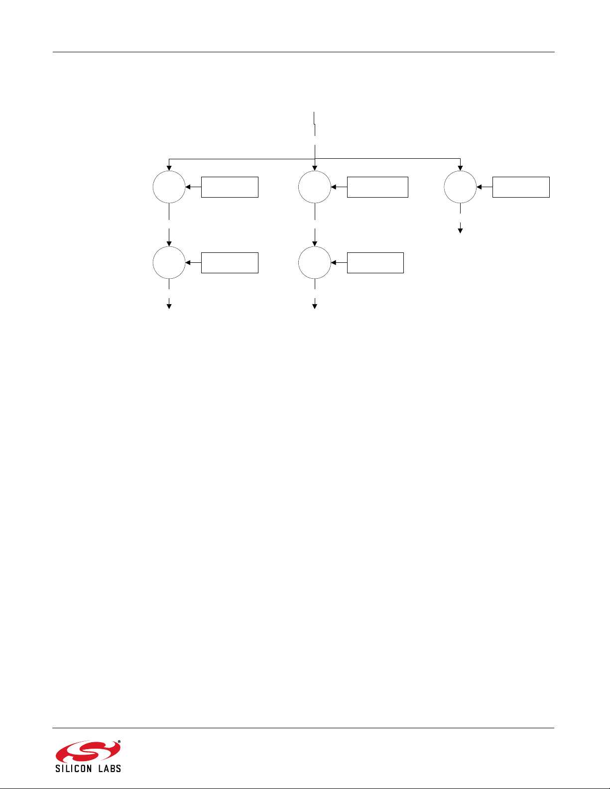
3.4. Key Handling
Application
Level
MK: Master Key
SK: Session Key
RKE_MK
Function
Level
AES_128AES_128 AES_128Node_Association Node_ButtonPress Functionzzzzzzzz
Btn_K
Session
Level
FuncX_K
Assoc_K
AES_128
12byte padding(0) +
Node Addr
Assoc_SK
AES_128
12byte padding(0) +
Node Addr
Btn_SK
Si4010-Keyfob-AES-DEMO
Figure 3. SRW AES128 Applications Key Hierarchy
AES keys used in the demos are generated according to the hierarchy shown in Figure 3. Only the Application
level keys are stored on the receiver board. The function level keys are calculated at power-up. The Session level
keys are calculated at their first use.
In the key fobs Function level, keys are not generated but only stored to save power. The Session level keys are
calculated at each power up.
The Assoc_SK is used for association packets, and the Btn_SK is used for encrypting the messages generated by
a button press.
3.5. Key Fob Firmware Description
The complete project of the program used in the demo key fob can be fo und in the Si4 010 documentation kit in the
“rke_demo” folder.
The key fob wakes up for button push or battery insert. If the battery was inserted, the vSys_FirstPowerUp() API
function is called, which shuts down the chip after 600 ms. This is for safe startup in case of battery contact
bouncing. Upon button push wakeup, the system variables and hardware control registers are initialized first, and
the session keys used in the AES encoding are generated from the function keys and the device address. Then,
button debouncing is made.
If a valid button push is detected, first a packet is assembled and transmitted six times for the LED receiver demo
board used in the Si4010 Simplified Key Fob Demo Kit (see details in “AN516: Si4010 Simplified Key Fob Demo
Quick Start Guide”). Then, a packet is assembled according to the description in the previous chapters. It is
transmitted in FSK modulation for the Si4313 receiver board (part of this kit), and then also in OOK modulation.
The next step is to increment the sync counter stored in the MTP memory.
If there is no valid button push detected for 3.2 s, the program shuts down the chip.
Rev 1.1 5
Page 6

Si4010-Keyfob-AES-DEMO
Wake up
Battery
Insert?
vSys_FirstPowerUp()Yes Shutdown
vSys_Setup( 15 )
Initialize application
Measure Vbat
Measure temp
Generate session keys
No
Button
pushed?
Timeout?No
Shutdown
Yes
No
Assemble packet for the LED
demo
Yes
Is button
valid for
receiver?
Assemble packet for Si4313
Set RF parameters
Transmit packet
Set RF parameters
Transmit packet
Yes
No
Assemble packet for Si4313
Set RF parameters
Transmit packet
Increment sync
counter
3.5.1. Key Fob Firmware Flowchart
6 Rev 1.1
Figure 4. Key Fob Firmware Flowchart
Page 7

Si4010-Keyfob-AES-DEMO
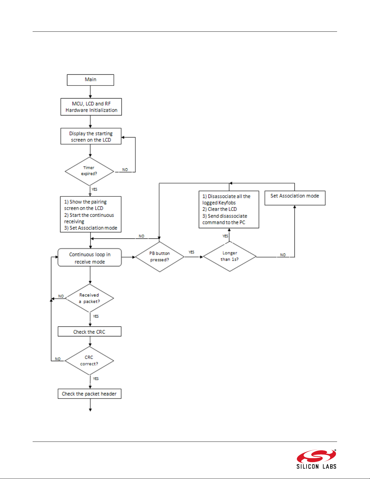
3.6. Receiver Board Firmware Description
The Si4313 RX board receives the packets from the Si4010 key fob, and, by the packet headers, it decides what
kind of packet was received. Two packet types can be received: association packets or button press packets. The
Si4313 RX board has two operation modes: Association mode and Button press mode. A key fob can only
associate when the Si4313 RX board is in Association mode. If the Si4313 is in Button press mode, then the
association packet will be discarded. During the first power up, the Si4313 RX board goes into Association mode,
and, after every key fob association, the firmware goes into Button press mode. The board can go back to
Association mode if the PB button is pressed. After an Si4010 key fob associates to the Si4313 RX board, the RX
board can receive the button press packets. At every packet reception, the firmware updates the LCD and sends
an indication message to the PC via the UART interface. The LCD displays the associated key fob serial numbers
and the number of the las t button pressed on the key f ob. However, the firmware stores more information about
each associated key fob, such as AES ke ys, temperature, battery level, etc. Figure 5 shows a flow chart of the
receiver board firmware.
Rev 1.1 7
Page 8
Si4010-Keyfob-AES-DEMO
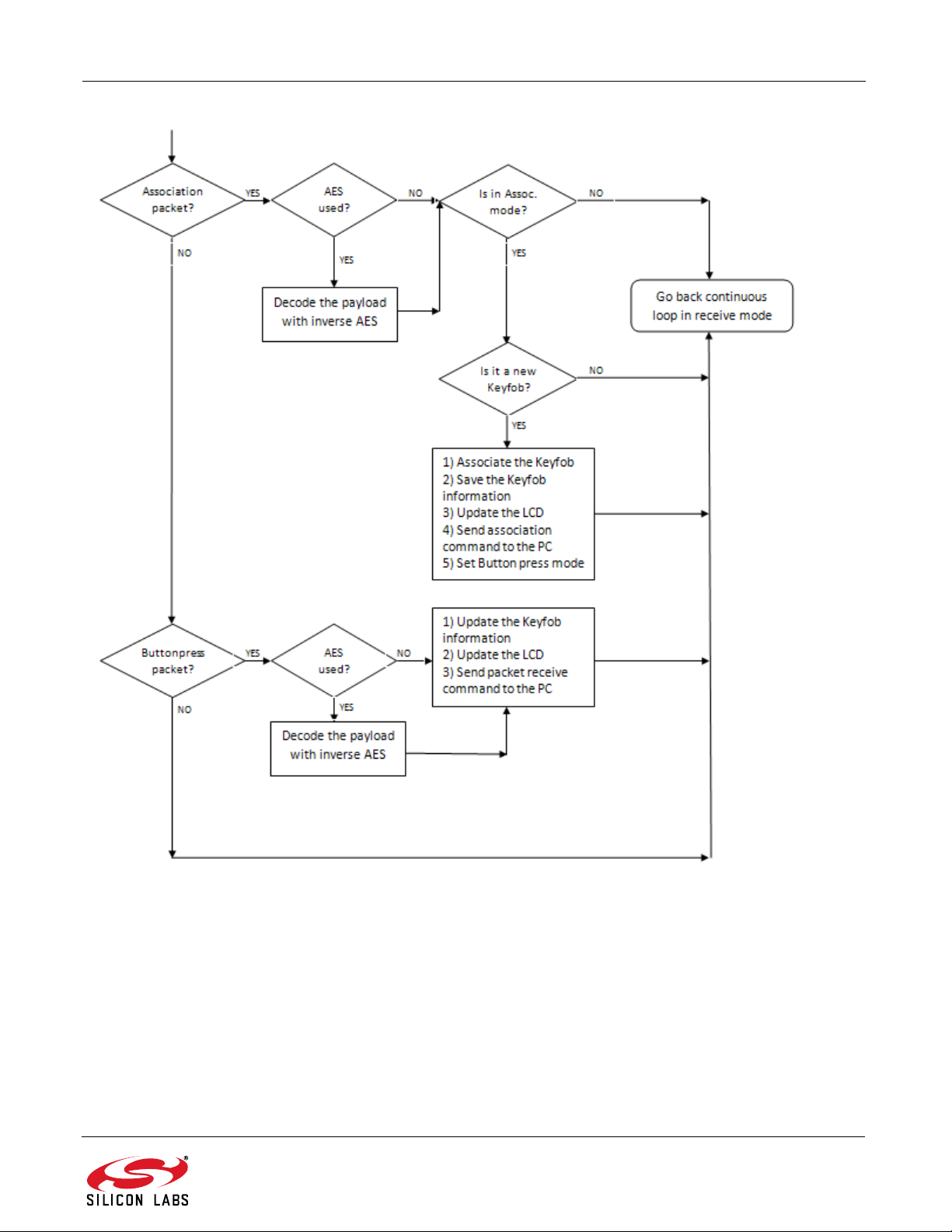
3.6.1. Receiver Board Firmware Flowchart
Figure 5. Basic Program Structure Block Diagram (1 of 2)
8 Rev 1.1
Page 9
Si4010-Keyfob-AES-DEMO
Figure 6. Basic Program Structure Block Diagram (2 of 2)
For details on how to program the Si4010, see the following documentation:
Si4010 Data Sheet
AN370: Si4010 Software Programming Guide
Si4010 Development Kit User's Guide
Rev 1.1 9
Page 10

Si4010-Keyfob-AES-DEMO
4. Demo Quick Start Guide
1. The first step is to insert the CR2032 battery into the key fob demo board and then place the board with the
battery into the plastic key fob case. Pushing any key will flash the LED on the key fob.
2. Connect the antenna into the SMA connector of the 4313-DACB_ANY receiver board.
3. Power up the Si4313 Receiver board by connecting it to the PC's USB port or by inserting batteries (3xAA) at
the back side of the board.
4. Switch the “S1” power supply switch to the proper p osition. If the board is supplied from the USB port, switch to
the “USB” state, or, if the board is supplied from the batteries, switch to the “Bat.” state.
5. After switching on the board, the LCD shows the Silicon Laboratories logo and the firmware version information.
The demo shows this information three times during the startup. This startup process can be skipped if any of
the PB1–PB3 button is pressed on the board.
6. On the next screen set the desired receive frequency using PB1 (+) and PB2 (–) buttons. Then step to the next
screen by pushing the PB3 (GO) button.
7. Wait until the following screen appears.
8. Pair the key fob with the Receiver board by pressing the LEFT and the RIGHT buttons togethe r on the key fob.
If the key fob can be associated to the receiver board, then the serial number of the key fob appears on the
display.
Note: Only four key fobs can be associated at the same time to the receiver board. The PB3 butto n on the re ceiver b oard has
to be pressed shortly before every key fob association.
9. When the key fob is associated to the RKE receiver board, press any button on the key fob. The LCD screen
shows the number of the depressed button.
10 Rev 1.1
Page 11

Si4010-Keyfob-AES-DEMO
10.If the PB3 bu tt on is pres se d for long e r than 2 s and then rele as ed , th e RKE rec eiv er boa rd disa sso cia te s all
associated key fobs. If you want to use the key fob again then it is required to be paired again. Refer to Step 7
for instructions on how to perform the pairing. In this case, the key fobs should associate again.
The code used in the transmitter of this key fob demo application can be found in the documentation kit in the
\Si4010 projects\rke_demo folder.
Rev 1.1 11
Page 12

Si4010-Keyfob-AES-DEMO
5. Software Installation
The provided software pack contains all the documentation and files needed to develop a user application. It also
contains example applications using API functions and the key fob demo application.
The directory structure of the software examples is as follows:
+--Si4010_projects
| +--aes_demo
| | +--bin .. Keil uVision and SiLabs IDE files
| | +--out .. output directory for Keil toolchain
| | +--src .. aes_demo source code
| +--common
| | +--lib .. Si4010 additional API functions library
| | +--src .. Si4010 required files
| +--fcast_demo .. frequency casting (tuning) demo
| | +--bin
| | +--out
| | +--src
| +--fstep_demo .. frequency two step tuning demo
| | +--bin
| | +--out
| | +--src
| +--tone_demo .. continuous wave (tone) demo
| | +--bin
| | +--out
| | +--src
| +--keyfob_demo .. simple keyfob demo
| | +--bin
| | +--out
| | +--src
| +--rke_demo .. advanced keyfob demo with AES
| | +--bin
| | +--out
| | +--src
Copy the directory structure in a directory of your choice. It is recommended to keep the structure of the
Si4010_projects folder to allow the compiler to find the Si4010 common files. Each project has a *.wsp project file
in the bin folder that contains all the settings of the IDE for the project, including the relative path of the common
files.
12 Rev 1.1
Page 13

Si4010-Keyfob-AES-DEMO
6. SiLabs IDE Run
Download the SiLabs IDE (Integrated Development Environment) from
http://www.silabs.com/products/mcu/Pages/SiliconLaboratoriesIDE.aspx and install it on your computer. To run the
Silicon Labs IDE, open the *.wsp project file.
7. Keil Toolchain Integration
The project files in examples assume that the Keil toolchain is installed to C:\Keil directory. The location of the Keil
toolchain can be easily changed in the Silabs IDE in the Project—Tool Chain Integration menu. An evaluation
version of the Keil toolchain can be downloaded from the Keil web site, http://www.keil.com/. This free version has
2 kB code limitation and starts the code at 0x0800 address. The Keil free evaluation version can be unlocked to
become a 4k version with no code placement limitation by following the directions given in application no te “AN104:
Integrating Keil 8051 Tools into the Silicon Labs IDE”, which covers Keil toolchain integration and license
management. Unlock code can be found on the WDS CDROM in the root fold er in the Keil_lice nse_ number.txt file.
Contact your Silicon Laboratories sales representative or distributor for application assistance.
For the complete development platform containing debug adapter and development boards, see Silicon
Laboratories’ Key Fob Development Kit (P/N 4010-DKKF_434 or 4010-DKKF_868).
Rev 1.1 13
Page 14

Simplicity Studio
One-click access to MCU tools,
documentation, software, source
code libraries & more. Available
for Windows, Mac and Linux!
www.silabs.com/simplicity
MCU Portfolio
www.silabs.com/mcu
Disclaimer
Silicon Laboratories intends to provide customers with the latest, accurate, and in-depth documentation of all peripherals and modules available for system and software implementers
using or intending to use the Silicon Laboratories products. Characterization data, available modules and peripherals, memory sizes and memory addresses refer to each specific
device, and "Typical" parameters provided can and do vary in different applications. Application examples described herein are for illustrative purposes only. Silicon Laboratories
reserves the right to make changes without further notice and limitation to product information, specifications, and descriptions herein, and does not give warranties as to the accuracy
or completeness of the included information. Silicon Laboratories shall have no liability for the consequences of use of the information supplied herein. This document does not imply
or express copyright licenses granted hereunder to design or fabricate any integrated circuits. The products must not be used within any Life Support System without the specific
written consent of Silicon Laboratories. A "Life Support System" is any product or system intended to support or sustain life and/or health, which, if it fails, can be reasonably expected
to result in significant personal injury or death. Silicon Laboratories products are generally not intended for military applications. Silicon Laboratories products shall under no
circumstances be used in weapons of mass destruction including (but not limited to) nuclear, biological or chemical weapons, or missiles capable of delivering such weapons.
Trademark Information
Silicon Laboratories Inc., Silicon Laboratories, Silicon Labs, SiLabs and the Silicon Labs logo, CMEMS®, EFM, EFM32, EFR, Energy Micro, Energy Micro logo and combinations
thereof, "the world’s most energy friendly microcontrollers", Ember®, EZLink®, EZMac®, EZRadio®, EZRadioPRO®, DSPLL®, ISOmodem ®, Precision32®, ProSLIC®, SiPHY®,
USBXpress® and others are trademarks or registered trademarks of Silicon Laboratories Inc. ARM, CORTEX, Cortex-M3 and THUMB are trademarks or registered trademarks of
ARM Holdings. Keil is a registered trademark of ARM Limited. All other products or brand names mentioned herein are trademarks of their respective holders.
Silicon Laboratories Inc.
400 West Cesar Chavez
Austin, TX 78701
USA
SW/HW
www.silabs.com/simplicity
Quality
www.silabs.com/quality
Support and Community
community.silabs.com
http://www.silabs.com
 Loading...