

Page 1

Si1120-EK
Si1120 EVALUATION KIT USER ’S GUIDE
1. Kit Contents
The Si1120 Evaluation Kit contains the following items:
Si1120 Evaluation Board
C8051F930 Target Board
Si1120EK Quick Start Guide
AC to DC Power Adapter
USB Debug Adapter (USB to Debug Interface)
2 USB Cables
2. Introduction
The Si1120EK is intended as an evaluation and development platform for the Si1120 infrared proximity and
ambient light sensor. Two PCBs are included in the kit: the Si1120 EVB shown in Figure 1, and the C8051F930-TB
shown in Figure 2. Although the C8051F930-TB is part of the development kit, the documentation in this user’s
guide will focus on the Si1120 EVB and the example firmware. For more specific information on the C8051F930
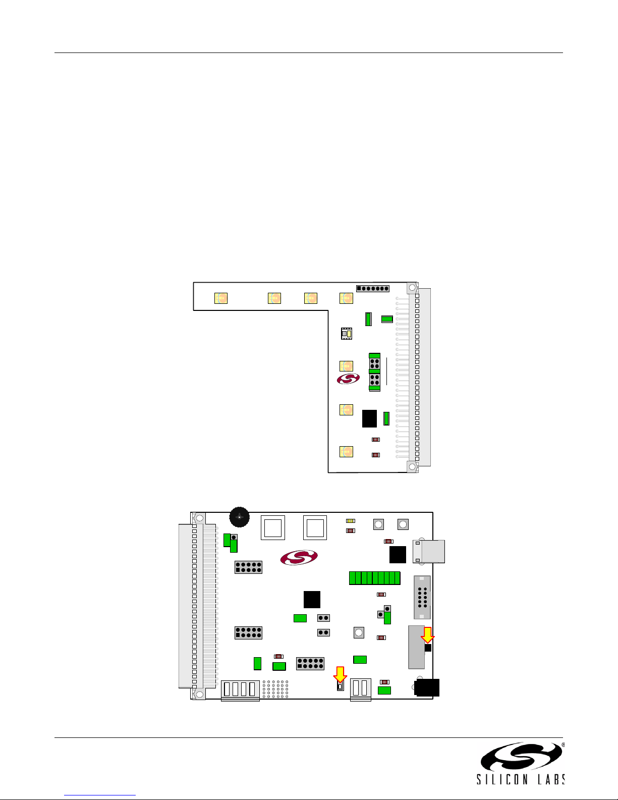
TB, refer to the “C8051F930-DK User’s Guide”. The main components of the Si1120 EVB are the Si1120 sensor
(U1), the infrared emitters (D1 through D7), and header J1 which allows for selection between different infrared
emitters on the board. On this PCB, the infrared emitters used are OSRAM part number SFH 4650-Z. These
emitters have a power rating of 45 mW and a half-angle of 20 degrees. Other emitters with different characteristics
may also be used, depending on the specific application requirements.
The example firmware for the kit measures the infrared light energy detected by the Si1120 while each of three
infrared emitters are independently activated. The infrared light from these emitters will be reflected back to the
Si1120 by any object that is placed in proximity to the sensor. X, Y, and Z positions can be calculated from these
measurements. If no object is close enough to the board, the measured signal levels will fall below pre-determined
thresholds, and the position calculations will not update. The example firmware is intended to be used in
conjunction with the QuickSense
the current position, the firmware is able to detect different gestures from the infrared sensor, as described in
Table 1 on page 8. The Si1120’s ambient light sensor (ALS) is also monitored by the firmware, which can
determine the type of ambient light presen t.
Note: The touchless infrared position detection implemented in the example is patent pending.
TM
Performance Analysis Tool to provide user feedback. In addition to calculating
3. Getting Started
The Si1120 Evaluation Kit requires some PC software to be installed, as well as some basic hardware setup of the
boards included in the kit.
3.1. Software Download and Installation
1. Browse to the Si1120 Evaluation Kit page at the URL http://www.silabs.com/Si1120EK.
2. Download and install the latest CP210x USB-to-UART Virtual COM Port (VCP) driver. This driver is necessary
to establish serial communications with the board.
3. Download and install the latest version of QuickSense
part of this package, and is an integral part of the example firmware functionality.
4. (Optional) Download and install the Silicon Laboratories IDE and the Si1120 Evaluation Kit package. This will
enable programming and debugging of the example source code. Note that the firmware is pre-loaded into the
board during manufacturing. The IDE and board package are needed to upgrade or modify the firmware.
Rev. 0.1 12/09 Copyright © 2009 by Silicon Laboratories Si1120-EK
TM
Studio. The QuickSense Perfo rmance Analysis Tool is
Page 2
Si1120-EK
P1
J3
VTX0
VDD
B1
J4
J9
J1
VTX0
VTX0
J2
GND
MD
SC
PRX
STX
TXO
VDD
U1
D1
D6 D7D5
D2
D3
D4
SILICON LABS
Si1120 EVB
P0.2 P0.3
J3
J4
J2
`
P3
CP
2103
U3
P2
DEBUG
J9
USB POWER
RESET
P1.6
P1.5
POWER OFF BEFORE
SW4
SWITCHING MODE
2 CELL
1 CELL
J17
IMEASURE
H2
SILICON LABS
www.silabs.com
H1
J6
VDD/DC+
J5
J7 J13
F930
U1
J14
J11
J10
VBAT
WALL_PWR
AAA_BAT
COIN_CELL
TOUCH SENSE SWITCH
P2.0
TOUCH SENSE SWITCH
P2.1
P1.4
J15
GND
J16
R15
J12J8
+3VD
+1VD
VBAT
J1
SW5
ON
OFF
SW2 SW3
PORT2
PORT1
SW1
PORT0
C8051F930-TB
P1
3.2. Hardware Setup
1. Ensure the shorting blocks are configured for basic operation on both boards, as shown in Figure 1 and
Figure 2.
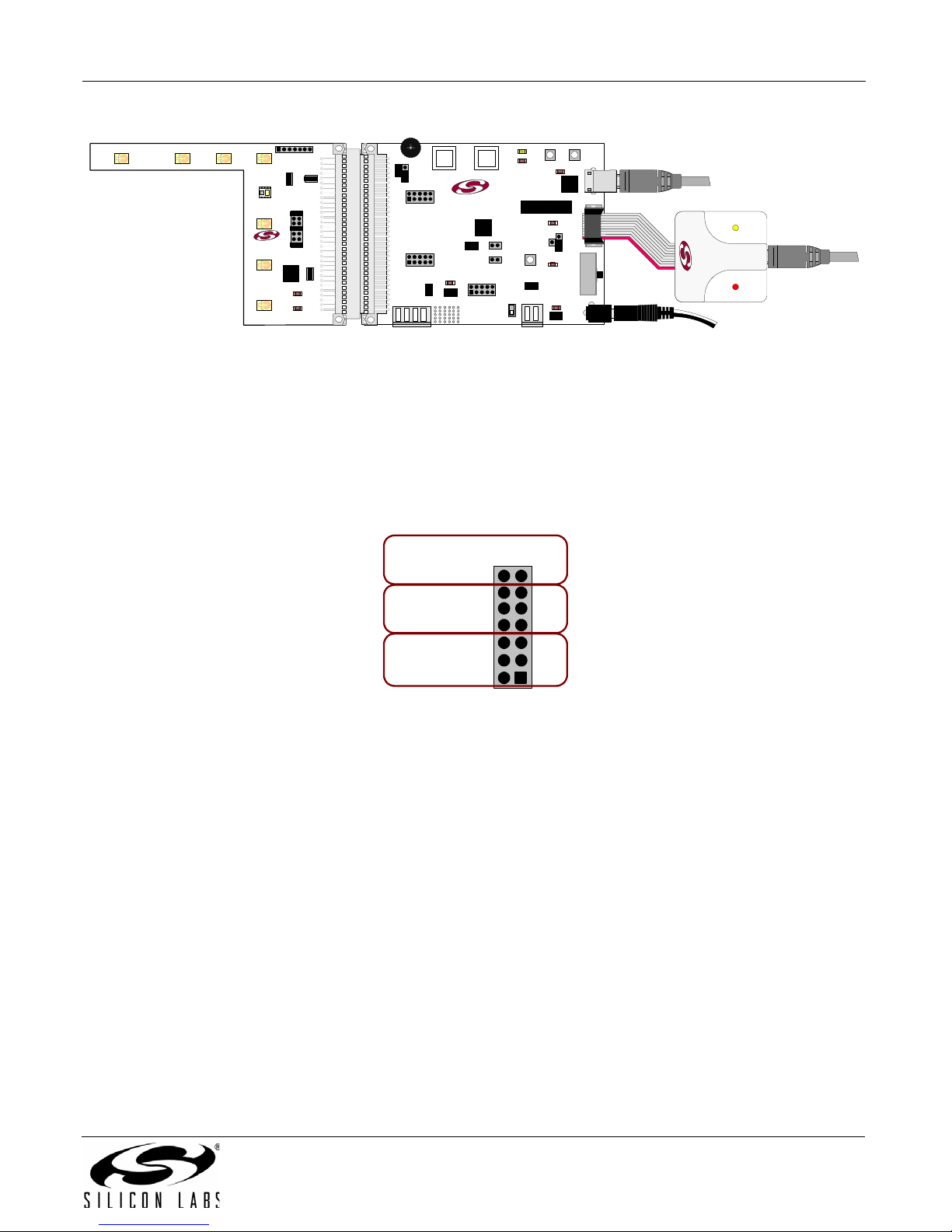
2. Connect the Si1120 EVB to the 96-pin connector on the C8051F930 TB.
3. Connect the USB Debug Adapter to the DEBUG connector on the C8051F930 TB with the 10-pin ribbon cable.
4. Connect one end of a USB cable to the USB connector on the USB Debug Adapter, and the other end to a USB
Port on the PC.
5. Verify that a shorting block is installed on J17 of the C8051F930 TB and that SW5 is in the ON position.
6. Connect the ac/dc power adapter to power jack P1 on the C8051F930 TB (Optional).
7. Connect one end of a USB cable to connector P3 on the C8051F930 TB, and the other end to a USB port on
the PC. Note that the CP210x VCP drivers should have been inst alled during the software setup described in
“3.1. Software Download and Installation” . If the drivers are installed correctly, a dialog box will pop up notifying
the user that a new USB device has been found.
Refer to Figure 3 for the full hardware connection diagram.
Figure 1. Si1120 Evaluation Board—Shorting Block Settings
2 Rev. 0.1
Figure 2. C8051F930 Target Board—Shorting Block and Switch Settings
Page 3
Si1120-EK
Communication
with PC
`
CP
210
3
SILICON LABS
www.silabs.com
F930
C8051F930-TB
P1
SILICON LABS
Si1120 EVB
Debug
Connection
to PC
AC/DC
Adapter
SILICON LABS
J1
Select Corner Emitter
(D1 Only)
D1
D7
D6
D5
D2
D3
D4
Select “X”
Axis Emitter
Select “Y”
Axis Em itter
Figure 3. Hardware Setup
3.2.1. Si1120 EVB Header J1 Settings
To function properly with the demonstration firmware, the shorting blocks on header J1 should be set as indicated
in Figure 1. However, these can be set differently, according to the application. The corner emitter is fixed at D1,
but a shorting block point is provided for debug purposes. The “X” and “Y” axis emitters can each be moved
between three different positions on the board, as sh ow n in Fig ur e 4.
Figure 4. Header J1 Setup
Rev. 0.1 3
Page 4

Si1120-EK
4. Software Overview
There are several software packages available to support the example firmware that is pre-loaded on the board.
The primary package that is required for functionality is QuickSense
Performance Analysis T ool, which can be used to collect data from the board over the USB interface, and display it
graphically on screen.
Optional software packages include the Silicon Labs Integrated Development Environment (IDE), and the Si1120
Evaluation Kit package. The Silicon Labs IDE provides a means of developing code for the C8051F930 and uses
the USB Debug Adapter to program the MCU and perform in-system debugging. For users wishing to modify the
example code or download the latest version of firmware into the board, the Si1120 Evaluation Kit installation
package contains board-specific materials such as the latest version of the pre-bu ilt firmwa re .HEX im age an d the
firmware example source code.
TM
Studio. QuickSense Studio contains the
4.1. QuickSense Studio
The QuickSense Studio software facilitates rapid code development and analysis for applications using the Silicon
Labs family of QuickSense products. QuickSense Studio is comprised of multiple programs that guide users
through an intuitive development flow, including graphical configuration wizards, firmware templates, and
performance monitoring to o ls. T h ese programs interface with the QuickSense Firmware API, a highly configurable
open-source firmware library that provides support for many different applications, from simple buttons to complex
algorithms like gesture recognition. The main component of QuickSense Studio used by the Si1120 Evaluation Kit
is the Performance Analysis Tool, which is described in more detail in "5. Using the Si1120EK With the QuickSense
Performance Analysis Tool" on page 6.
Figure 5. Silicon Labs QuickSense Studio Software
For detailed information on the QuickSense Studio software, please see the QuickSense Studio User’s Guide
available on the Silicon Labs QuickSense webpage (http://www.silabs.com/quicksense) in the QuickSense Studio
section.
4 Rev. 0.1
Page 5

Si1120-EK
4.2. Silicon Laboratories IDE
The Silicon Laboratories IDE integrates a source-code editor, a source-level debugger, and an in-system Flash
programmer. This tool can be used to develop and debug code for the C8051F930 MCU. The use of several thirdparty compilers and assemblers is supported by the IDE.
4.2.1. IDE System Requirements
The Silicon Laboratories IDE requirements:
Pentium-class host PC running Microsoft Windows 2000 or newer.
One available USB port.
4.2.2. Third Party Toolsets
The Silicon Laboratories IDE has native support for many 8051 compilers. The full list of natively supported tools is
as follows:
Keil
IAR
Raisonance
Tasking
SDCC
4.2.3. Downloading the Example Firmware Image
The Si1120 Evaluation Kit installer package installs the firmware source code as well as a pre-built .HEX image
that can be downloaded directly into theC8051F930 target board. The firmware source code and an example IDE
project is located in the default path C:\SiLabs\MCU\QuickSense_Studio\Kits\Si1120EK\Firmware\. The pre-built
.HEX image is located in the default path C:\SiLabs\MCU\QuickSense_Studio\Kits\Si1120EK\Firmware\Release\.
Follow the steps below to update or refresh the .HEX image in the C8051F930-TB:
1. Connect the hardware as described in "3.2. Hardware Setup" on page 2.
2. Launch the Silicon Labs IDE, and click on Options->Connection Options.
3. Select “USB Debug Adapter” and then select the connected adapter from the list (it should show up as “EC3”
followed by a serial number).
4. Select “C2” as the debug interface, and press “OK”.
5. Connect to the board by pressing the “Connect” icon, or using the keyboard shortcut Alt+C.
6. Click on the “Download” icon, or use the keyboard shortcut Alt+D.
7. In the download dialog window, click “Browse”.
8. Change to Files of Type “Intel Hex (*.hex)” and then browse to select the file Si1120EK.hex in the default path
C:\SiLabs\MCU\QuickSense_Studio\Kits\Si1120EK\Firmware\Release\.
9. Click “Open” then “Download”.
10.To run the new image, either press “Run” or “Disconnect” in the IDE.
Rev. 0.1 5
Page 6

Si1120-EK
5. Using the Si1120EK With the QuickSense Performance Analysis Tool
The Si1120 Evaluation Kit is supported by the QuickSense Performance Analysis Tool. The Performance Analysis
Tool allows users to see real-time measured infrared proximity and ambient light measurements from the Si1120 in
a graphical form, as well as the calculated values for distance from each of the infrared LEDs and the X, Y, and Z
positions. Additionally, recognized gestures and the ambient light conditions can be displayed in dedicated group
windows. The communications interface to the Si1120 EVB is provided over USB (P3) via the CP2103 USB-toUART bridge, and the QuickSense Firmware API. For a more detailed description of the QuickSense Firmware API
or the Serial Interface, see “AN366: QuickSense API.”
To use the Performance Analysis Tool with the Si1120 Evaluation Kit:
1. Connect the C8051F930-TB to the PC using a USB cable.
2. Launch the Performance Analysis Tool from QuickSense Studio, or from the Start menu.
3. Select the board from the “Devices” menu (it will normally show up as the last COM port in the list).
4. Select the channels you wish to display on the picture of the Si1120 EVB that appears. The individual channels
available are described in “5.1. Channel Selection” .
5. Click the green “Acquisition” arrow to begin collecting data.
Figure 6 shows an example of the Performance Analysis Tool output when connected to the board. To generate the
graph, a hand was moved above the Si1120EVB. The selected traces shown are the calculated X and Y positions.
The green trace represents the X position, while the yellow trace represents the Y position of the hand above the
board.
Figure 6. Performance Analysis Tool Main Window
6 Rev. 0.1
Page 7

Si1120-EK
5.1. Channel Selection
Selecting which channels to display is a simple matter of checking the appropriate boxes over the board
photograph, shown in Figure 7.
Figure 7. Channel Selection
There are three different types of measurements available from the example firmware:
1. Raw infrared proximity and ambient light measurements. The infrared channels are indicated by the check
boxes near the infrared emitters (D1-D7), while the amb ient light channel is the check b ox over the Si1120 (U1).
The data for these channels represents a measurement of the duration of the Si1120’s PRX low time, as seen
by the C8051F930 MCU. The Y axis indicates the number of 6.125 MHz clock cycles that occurred while PRX
was low. The maximum output limit of the Si1120 is 2 ms, which would correspond to 12250 counts of a
6.125 MHz clock.
2. Linearized distance measurements for each IR channel. The raw proximity values output from the Si1 120 will be
exponentially larger the closer an object is to the sensor. The channels labeled “Radius 1”, “Radius 2” and
“Radius 3” are linearizations of the raw data output from the sensor when illuminating the three different
selected emitters. To use the example effectively, the shorting blocks on header J1 should be set according to
the diagram in Figure 1. This will select D1, D4, and D7 as the three reference emitters.
3. Calculated coordinate measurements. The linearized IR proximity measurements are used to calculate X (leftto-right), y (up-to-down) and a Z (far-to-near) measurements.
Due to the nature of infrared proximity measurements, the object’s size and reflectivity will have an impact on the
values measured.
Rev. 0.1 7
Page 8

Si1120-EK
5.2. Gestures and Ambient Light Conditions
In addition to infrared and ambient light measurements and distance calculations, the example firmware contains
algorithms for gesture recognition and ambient light condition detection. When connected to the board with the
Performance Analysis Tool, two group windows will appear, as shown in Figure 8. When a gesture is recognized by
firmware, the gesture name and parameter information will be added to the top of the 3D Gesture group. Four
gestures are supported by the example code. The parameters for each gesture are listed in Table 1. The detected
ambient light conditions (Sunlight, Incandescent/Halogen, or Fluorescent/CFL) will be displayed in the Light Type.
Figure 8. Performance Analysis Tool Group Windows
Table 1. Recognized Gestures
Gesture Name Parameter Parameter Range Description of Action
Swipe Left Speed 118 (Slow to Fast) Move hand rapidly from the right side to the left side
of the board.
Swipe Right Speed 118 (Slow to Fast) Move hand rapidly from the left side to the right side
of the board.
Swipe Up Speed 118 (Slow to Fast) Move hand rapidly from the bottom to the top of the
board.
Swipe Down Speed 118 (Slow to Fast) Move hand rapidly from the top to the bottom of the
board.
8 Rev. 0.1
Page 9

6. Schematic
Si1120-EK
Rev. 0.1 9
Figure 9. Si1120 EVB Schematic
Page 10

Si1120-EK
The information in this document is believed to be accurate in all respects at the time of publication but is subject to change without notice.
Silicon Laboratories assumes no responsibility for errors and omissions, and disclaims responsibility for any consequences resulting from
the use of information included herein. Additionally, Silicon Laboratories assumes no responsibility for the functioning of undescribed features
or parameters. Silicon Laboratories reserves the right to make changes without further notice. Silicon Laboratories makes no warranty, representation or guarantee regarding the suitability of its products for any particular purpose, nor does Silicon Laboratories assume any liability
arising out of the application or use of any product or circuit, and specifically disclaims any and all liability, including without limitation consequential or incidental damages. Silicon Laboratories products are not designed, intended, or authorized for use in applications intended to
support or sustain life, or for any other application in which the failure of the Silicon Laboratories product could create a situation where personal injury or death may occur. Should Buyer purchase or use Silicon Laboratories products for any such unintended or unauthorized application, Buyer shall indemnify and hold Silicon Laboratories harmless against all claims and damages.
CONTACT INFORMATION
Silicon Laboratories Inc.
400 West Cesar Chavez
Austin, TX 78701
Tel: 1+(512) 416-8500
Fax: 1+(512) 416-9669
Toll Free: 1+(877) 444-3032
Please visit the Silicon Labs Technical Support web page:
https://www.silabs.com/support/pages/contacttechnicalsupport.aspx
and register to submit a technical support request.
Silicon Laboratories, Silicon Labs, and QuickSense are trademarks of Silicon Laboratories Inc.
Other products or brandnames mentioned herein are trademarks or registered trademarks of their respective holders.
10 Rev. 0.1
 Loading...