

Page 1
Ethernet-DK
EMBEDDED ETHERNET DEVELOPMENT KIT USER’S GUIDE
1. Overview
The Embedded Ethernet Development Kit (Ethernet-DK) provides all the hardware and software required to
develop real-world embedded Ethernet applications using the industry proven CMX Micronet™ protocol stack and
high-performance Silicon Laboratories microcontrollers. The TCP/IP protocol stack is developed specifically for
embedded processors and is freely distributed in an easy-to-use library. A TCP/IP Configuration Wizard is provided
to generate a highly customized library optimized for user selected protocols. It also generates the framework code
required to use the library and a project file that can be managed in the Silicon Laboratories Integrated
Development Environment (IDE). Additional information about the TCP/IP library and Configuration Wizard,
including a detailed API description, can be found in application note “AN237: TCP/IP Library Programmer’s
Guide”.
The Embedded Ethernet Development Kit hardware includes a C8051F120 Target Board, AB4 Ethernet
Development Board, USB Debug Adapter, and all necessary cables to debug the MCU and connect it to an
Ethernet network. The C8051F120 Target Board features the 100 MIPS, 128 kB Flash, 8 kB RAM, 8051-based
C8051F120 MCU. The MCU network interface provided by the AB4 board consists of the CP2200 Ethernet
controller and an RJ-45 connector with integrated magnetics and LEDs. The TCP/IP Library includes a built-in
driver for the CP2200 and has a custom driver interface with auto-generated templates to allow drivers for any
Ethernet controller to be written.
The Silicon Labs IDE supports full-speed, non-intrusive MCU debugging and is bundled with an evaluation version
of the Keil C51 Toolchain allowing immediate application code evaluation in C. Projects with up to 4 kB of object
code and unlimited library code can be developed using the included toolset. Numerous application code examples
are included in the development kit and a walkthrough of an embedded web server demo is included in Section 6
on page 8.
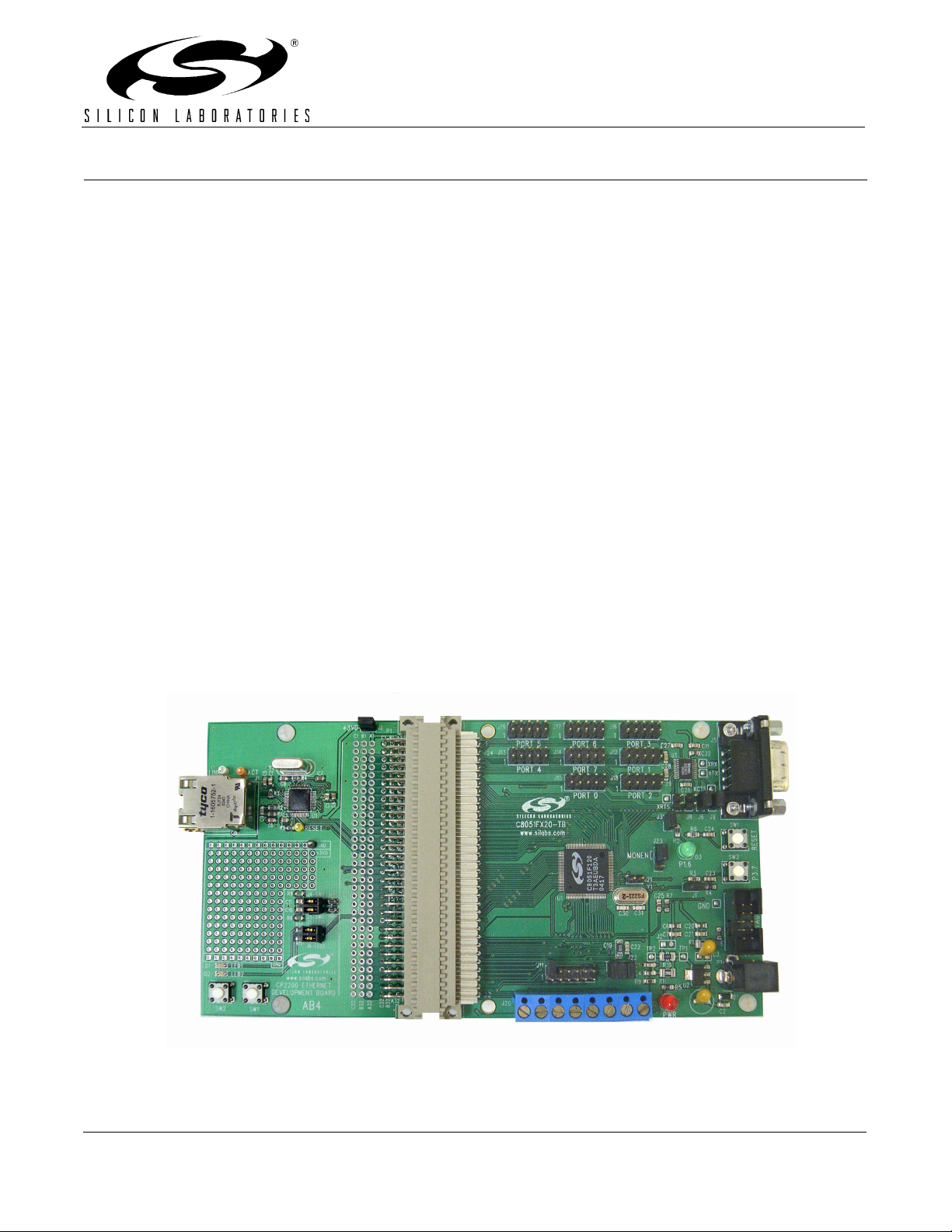
Figure 1. C8051F120TB Target Board and AB4 Ethernet Development Board
Rev. 0.5 6/06 Copyright © 2006 by Silicon Laboratories Ethernet-DK
Page 2

Ethernet-DK
2. Kit Contents
The Embedded Ethernet Development Kit contains the following items:
C8051F120 Target Board
AB4 Ethernet Development Board
CAT5e Ethernet Cable
Silicon Laboratories Evaluation Kit IDE and Product Information CD-ROM. CD content includes the
following:
Silicon Laboratories Integrated Development Environment (IDE)
Keil C51 Evaluation Toolchain (assembler, linker and C compiler with 4 kB object code generation and
unlimited library code usage)
Source code examples and register definition files
Documentation
TCP/IP Configuration Wizard
Embedded Ethernet Development Kit User’s Guide (this document)
Universal (100–240 V, 50–60 Hz) AC to DC Power Adapter
USB Debug Adapter (USB to JTAG/C2 Debug Interface)
USB Cable
Serial Cable
2 Rev. 0.5
Page 3
Ethernet-DK
3. Hardware Setup
The following instructions illustrate how to setup the hardware included with the kit.
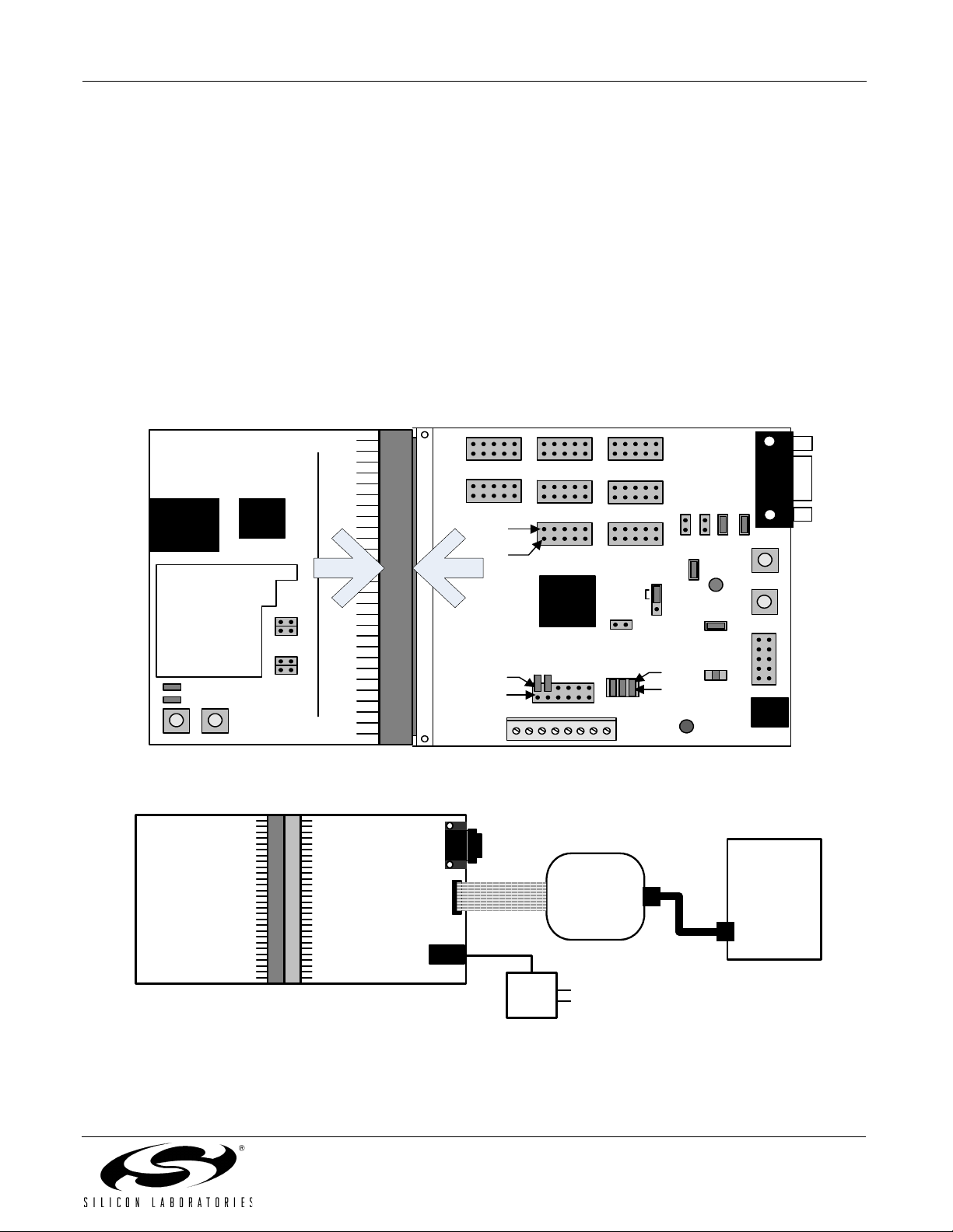
1. Connect the AB4 Ethernet Development Board to the C8051F120 Target Board at J24 (Figure 2). Apply
slight pressure to ensure the mating 96-pin connectors are firmly connected.
2. Using the ribbon cable, connect the USB Debug Adapter to the C8051F120 Target Board at the JTAG
header.
3. Connect one end of the provided USB cable to any available USB port on the PC.
4. Connect the other end of the USB cable into the USB connector on the USB Debug Adapter.
5. Connect the ac/dc Power Adapter to the C8051F120 Target Board at P1. This connection should power
both boards. Power is indicated by the "PWR" LED.
Note: The 'F120TB places a 2 Ω resistor in series with the power supply net powering the AB4 Board. We recom-
mend replacing this resistor with a 0 Ω resistor to prevent large voltage drops, possibly triggering a V
Monitor reset, when current demand increases.
DD
AB4 Ethernet
Development
Board
RJ45
Prototyping
Area
LED1
LED2
SW2 SW1
AB4 Ethernet
Development
Board
J24
Port 3Port 6Port 5
CP2200
J4
J3
J5
J6
Port 4
Pin 2
Pin 1
C8051F120
Target Board
Pin 2
Pin 1
J20
Port 7
Port 0 Port 2
C8051F12x
J11
MONEN
J21
J22
Port 1
J3
J23
Pin 2
Pin 1
PWR
Figure 2. Embedded Ethernet Development Board Attachment
Ribbon
C8051F120
Target Board
Cable
JTAG
USB
Debug
Adapter
J8J10 J6
P1.6
J1
R1
USB
Cable
J5
J9
J4
P1
PC
USB Port
RESET
P3.7
JTAG
AC / DC
Adapter
Figure 3. Embedded Ethernet Development Kit Debug Connections
Rev. 0.5 3
Page 4

Ethernet-DK
4. Network Setup
The Embedded Ethernet Development Kit can be connected to an Ethernet network using a standard Ethernet
cable (see Figure 4) or directly to a PC using a crossover cable (see Figure 5). Table 1 describes the benefits of
using each of the connection methods. A standard Ethernet cable is included in the kit and crossover cables are
available for order from the Silicon Laboratories website, at www.silabs.com.
Table 1. Ethernet Cable Comparison
Standard Cable Crossover Cable
Remote access to embedded system. Distance from PC to embedded system is limited by
the length of the cable.
Multiple embedded systems may be networked and
accessed from the same (or multiple) PC(s).
Shared communication medium. System may experience packet delays under heavy network traffic. This
Only a single embedded system may be accessed
from a single PC.
Dedicated channel bandwidth. Good for achieving
consistent data throughput measurements.
effect is greatly reduced if using a switched network.
An existing network with wall outlet or a router/switch is
No additional hardware required.
required.
PC does not require any additional IP address configuration.
PC must be configured with a static IP address in
order to recognize embedded system.
Standard cable is included in development kit. Crossover cable must be purchased separately.
Embedded Ethernet
Development Kit
‘F120TB + AB4
Ethernet
Connector
PC
Ethernet
Connector
Ethernet
Cable
Ethernet
Router/
Switch
Or
Wall Outlet
Ethernet
Cable
Figure 4. Embedded Ethernet Network Connection (Standard Cable)
PC
Ethernet Crossover Cable
Ethernet
Connector
Figure 5. Embedded Ethernet Network Connection (Crossover Cable)
4 Rev. 0.5
Embedded Ethernet
Development Kit
‘F120TB + AB4
Ethernet
Connector
Page 5
Ethernet-DK
4.1. Network Setup Procedure
If using a standard cable:
1. Connect the AB4 Ethernet Development Board to an Ethernet wall outlet or to a router/switch using a
standard Ethernet cable.
2. Connect a PC to the same Ethernet network using a standard Ethernet cable.
If using a crossover cable:
1. Connect the AB4 Ethernet Development Board directly to a PC using an Ethernet crossover cable.
2. Configure the PC to have a static IP address. The steps below show how to configure a Windows PC to use
a static IP address.
a. Open the Network Connections Folder. This is accessible from the control panel or from the start menu by right-
clicking on My Network Places and selecting Properties.
b. Right-click on the Local Area Connection and select Properties.
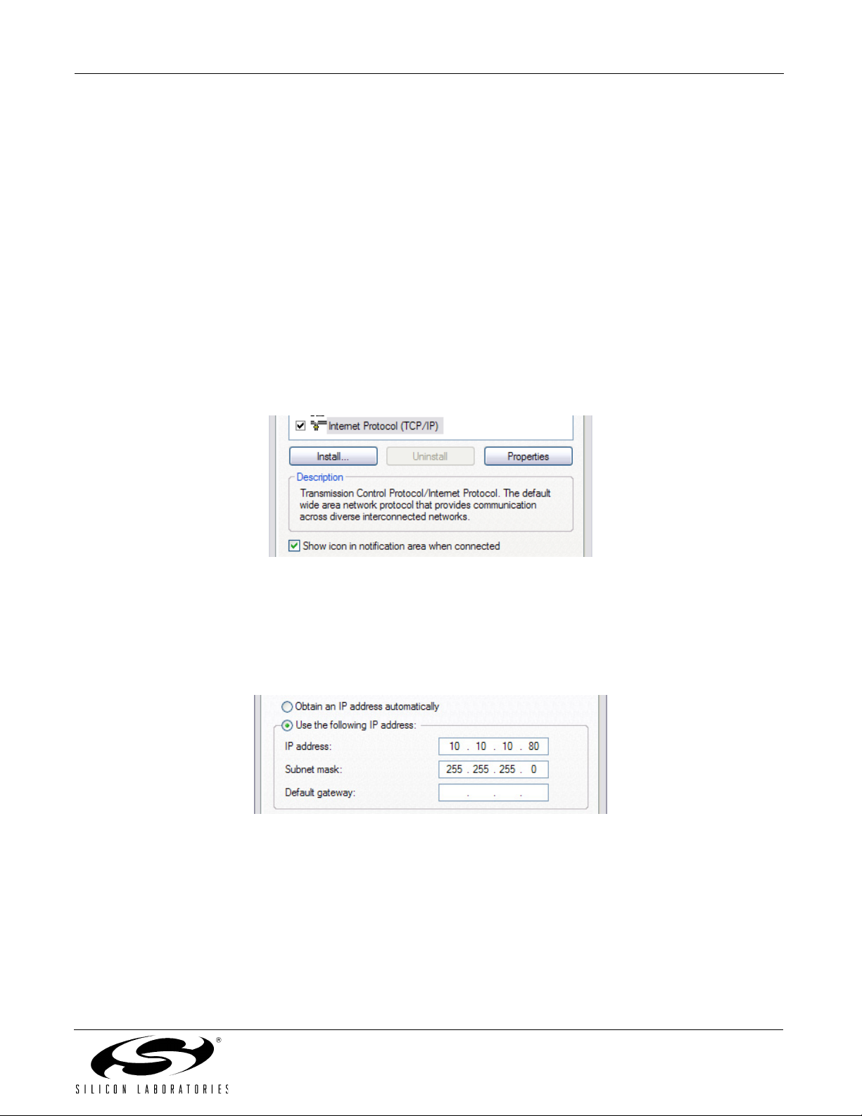
c. Select Internet Protocol (TCP/IP) and click Properties. Optionally, if the Show icon in notification area when connected
is checked, right-clicking the system tray icon will provide a quick shortcut to the LAN properties dialog and can be
used as an indicator that the network is functioning properly.
d. Select Use the following IP address and specify an IP address and subnet mask for the PC. For a subnet mask of
255.255.255.0, the embedded system’s IP address must match the first three octets of the PC’s IP address for the PC
to recognize the embedded system. See Section 4.2 for additional information about choosing the embedded
system’s IP address.
Note: When entering an IP or subnet address into the dialog box, the cursor will automatically advance to the next
field for a three digit octet. If entering a one or two digit octet, the spacebar, right arrow key, or ‘.’ can be pressed to
advance to the next field.
e. Click OK after the static IP address and subnet mask have been configured. The PC will now be able to access the
embedded system using a crossover cable.
Rev. 0.5 5
Page 6

Ethernet-DK
4.2. Selecting an IP Address for the Embedded System
For a PC to recognize an embedded system on a network, its IP address and subnet mask need to be configured.
Below are a few guidelines to follow when choosing an IP address for the embedded system. Figure 6 shows an
example of a compatible PC and embedded system IP address combination.
1. Find the IP address and Subnet mask for the PC. If a Default Gateway is specified, then save this address for
later use. If you are using a crossover cable, you may choose any IP address for your PC as long as the
Subnet mask allows it to recognize the embedded system.
2. The IP address chosen for the embedded system must match the PC’s IP address in all bit locations where
the Subnet mask is a 1 in order for the PC to recognize the embedded system. Otherwise, the PC will send
it’s request outside the local network.
3. Do not duplicate IP addresses or select a broadcast address. An IP address is considered a broadcast
address if all bits which are 0 in the Subnet mask are 1 in the IP address. Broadcast addresses with
additional 1s such as 10.10.255.255 (Figure 6) can be broadcast to nodes outside the local network.
4. The address 255.255.255.255 is known as the Ethernet broadcast address and is used when the Subnet
mask for the network is not known. Any packet transmitted to this address will reach all nodes on the local
network but cannot go further than the nearest router.
4.3. IP Address Selection Example
The example in Figure 6 shows the IP address and subnet mask of the PC we want to connect to the embedded
system. Since the first 24 bits of the subnet mask are 1, the first 24 bits of the embedded web server’s IP address
(shown in bold) must match the PC’s IP address. Only the least significant 8 bits may vary making the valid range
of IP addresses for the embedded web server 10.10.10.0 to 10.10.10.254 with the exception of 10.10.10.80 since
this address is already taken by the PC. 10.10.10.255 is reserved because it is the broadcast address for this
network.
PC IP Address
PC Subnet Mask
10 10 10 80
0000 1010 0000 1010 0000 1010 0101 0000
255 255 255 0
1111 1111 1111 1111 1111 1111 0000 0000
Embedded Web Server IP Address
10
10
0000 1010 0000 1010 0000 1010
163
10
1010 0011
(decimal)
(binary)
(decimal)
(binary)
(decimal)
(binary)
Figure 6. IP Address Selection Example
6 Rev. 0.5
Page 7

Ethernet-DK
5. Software Setup
The included CD-ROM contains the Silicon Laboratories IDE, Keil C51 toolset, and documentation including
datasheets, application notes, and an electronic version of this user’s guide. The instructions below describe how
to install the Embedded Ethernet Development Kit software. Refer to the readme.txt file on the CD-ROM for the
IDE release notes containing the latest information regarding supported devices, revision history, and known
issues.
1. Place the Embedded Ethernet Development Kit CD-ROM into the PC’s CD-ROM drive. An installer will
automatically launch, allowing you to install the IDE software or read documentation by clicking buttons on
the Installation Panel. If the installer does not automatically start when you insert the CD-ROM, run
autorun.exe, found in the root directory of the CD-ROM.
2. After the installation dialogue box appears, click the Install Development Tools button.
3. Follow the installation prompts to install the development tools. The following applications will be installed:
The Silicon Laboratories IDE will be installed by default in the “C:\SiLabs\MCU” directory.
The Embedded Ethernet examples will be installed by default in the
“C:\SiLabs\MCU\Examples\C8051F12x\Ethernet” directory.
The TCP/IP Configuration Wizard will be installed by default in the “C:\SiLabs\MCU\TCP-IP Config”
directory.
Shortcuts to the applications will be placed in the Start→Programs menu.
Rev. 0.5 7
Page 8
Ethernet-DK
6. Embedded Ethernet Tutorial
Now that the Embedded Ethernet Development Kit hardware has been set up, the software installed, and the
embedded system connected to a network, it is time to download firmware into the MCU and test its network
connectivity. The Embedded Ethernet Tutorial consists of four stages of increasing functionality and will allow the
user to quickly learn how to use the development kit hardware and software.
6.1. Stage 1—Basic Web Server
In the first demo stage, we will generate a “Hello World” web server with a single static web page using the TCP/IP
Configuration Wizard. We will learn how to PING the embedded web server and view the page in a web browser.
6.1.1. Generating a Project using the TCP/IP Configuration Wizard
The instructions below show how to generate a new project using the TCP/IP Configuration Wizard.
1. From the Windows Start menu, start the TCP/IP Configuration Wizard. The shortcut will be under the
Start→Silicon Laboratories menu. Alternatively, the Configuration Wizard can be started by double-clicking
TCPIP_Config.exe located by default in the “C:\SiLabs\MCU\TCP-IP Config” directory.
2. In the Communications Adapter section of the left window, check CP2200.
3. In the Device section of the left window, verify that C8051F12x is selected.
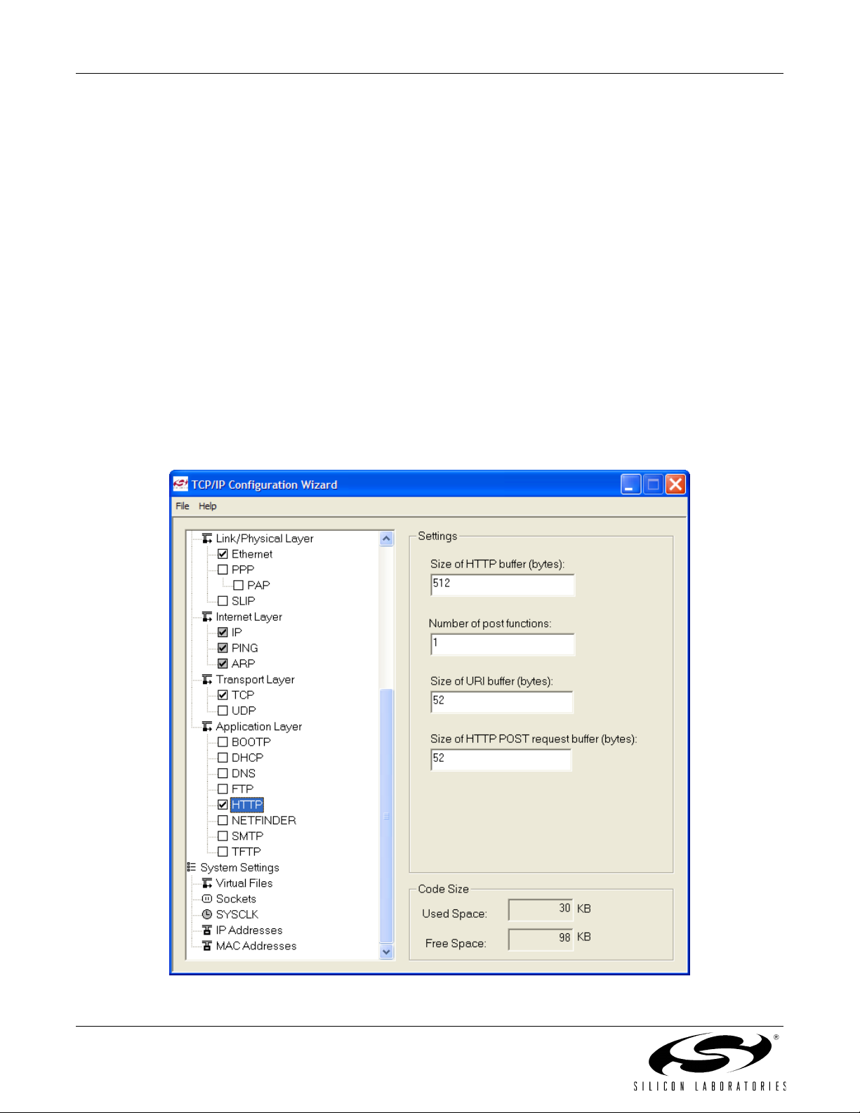
4. In the Protocol Settings section of the left window, make sure Ethernet is selected then check HTTP. The
lower level protocols required to run HTTP (e.g., TCP) will automatically be enabled (see Figure 7).
Figure 7. TCP/IP Configuration Wizard Protocol Selection
8 Rev. 0.5
Page 9
Ethernet-DK
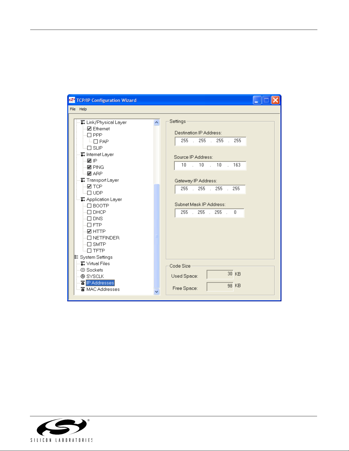
5. In the System Settings section of the left window, select IP Addresses.
6. In the right window, set the Source IP Address to the IP address of the embedded system.
7. If the Gateway IP Address and Subnet mask of the network are known, then fill in the addresses on the
right window (see Figure 8).
8. If using the CP2200, the MAC address field is ignored. The CP2200 Ethernet Controller contains a unique
factory-programmed MAC address stored in Flash memory.
Figure 8. TCP/IP Configuration Wizard IP Address Specification
Rev. 0.5 9
Page 10
Ethernet-DK
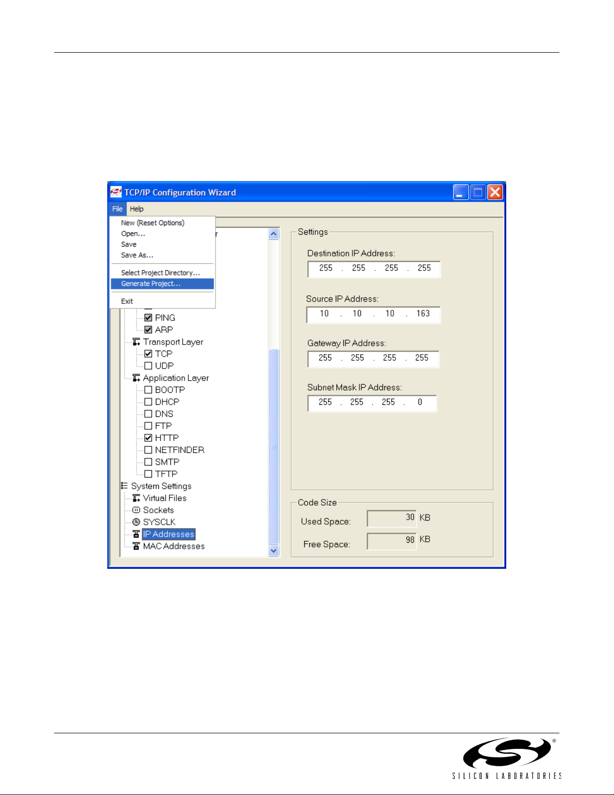
9. Save the selected configuration using the File→Save As menu.
10. Generate a new project with supporting firmware by selecting Generate Project from the File menu (see
Figure 9).
11. When prompted for a folder to save the project, browse to an empty directory or create a new directory.
Note: Any files in the selected directory will be overwritten. Click the OK button.
12. Click the OK button when the “Project generated successfully” message appears.
13. Close the TCP/IP Configuration Wizard.
Figure 9. TCP/IP Configuration Wizard Project Generation
10 Rev. 0.5
Page 11
Ethernet-DK
6.1.2. Programming the MCU
We will now build the project created by the TCP/IP Configuration Wizard and download the firmware to the MCU
using the Silicon Laboratories IDE.
1. From the Windows Start menu, start the Silicon Laboratories IDE. The shortcut will be under the
Start→Silicon Laboratories menu. Alternatively, the Silicon Labs IDE can be started by double-clicking
IDE.exe located by default in the “C:\SiLabs\MCU” directory.
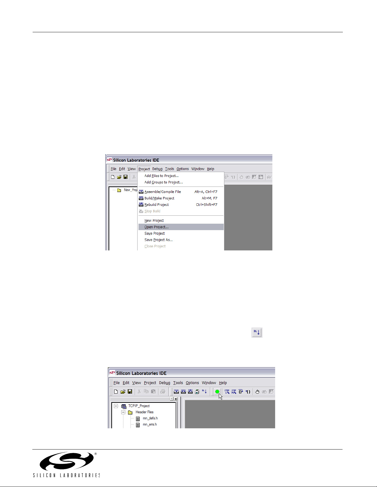
2. After the splash screen disappears, open the generated project using the Project→Open Project menu
command. Browse to the directory where the TCP/IP project was generated. Select TCPIP_Project.wsp, and
click the Open button.
Note: An example project is available by default in the
“C:\Silabs\MCU\Examples\C8051F12x\Ethernet\HTTP\web-server-1” directory. This project is identical to the
one generated in the previous steps.
Figure 10. Opening a Project in the Silicon Labs IDE
3. If you would like to view the source code, double-click on main.c on the left hand side of the screen. Source
code modification is not required to run this demo.
4. Build the project. This can be done by clicking on the Build/Make Project button in the toolbar, selecting
Project→Build/Make Project from the menu, or pressing the F7 shortcut key.
5. Click
6. Download the project to the target by clicking the Download Code button in the toolbar.
7. Run the demo by clicking the Go button in the toolbar (
.
the
Connect
Note: If you receive the error message “Communication could not be established with the specified serial
adapter”, open the Connection Options Dialog by selecting
Verify that the
pressing the shortcut key
button in the toolbar or select
USB Debug Adapter
F5
.
is selected and that the debug interface is set to
Debug→Connect
Options→Connection Options
see Figure 11), selecting
from the menu
Debug→Go
.
from the menu.
JTAG.
from the menu, or
Figure 11. Running the Demo in the Silicon Labs IDE
Rev. 0.5 11
Page 12

Ethernet-DK
6.1.3. Testing Connectivity Using PING
After pressing GO, the MCU will be executing the TCP/IP stack firmware. The LEDs on the RJ-45 Ethernet
connector should light up if the MCU is connected to a network. Once the network router detects the presence of
the embedded system, it will be accessible from any PC connected to the same network. This usually takes a few
seconds, but can take over 30 seconds depending on the size of the network. The delay is minimized if the
embedded system is connected directly to a PC using a crossover cable.
The PING utility is available on all PCs and allows the user to check if the MCU is responding to network requests.
The instructions below show how to ping the embedded system.
1. Using the Windows Start menu, select Start→Run.
2. When the Run dialog appears, type in cmd. A black terminal window should appear.
3. At the prompt, type ping followed by a space and the IP address of the embedded system as shown in
Figure 12. Press the Enter key when finished.
4. If the PC is able to communicate with the embedded system, then ping will report the number of milliseconds
it took to receive a reply from the embedded system. Otherwise, it will report “Request timed out”.
Figure 12. Pinging the Embedded System
6.1.4. Accessing the Embedded System using a Web Browser
Once the ping utility is able to receive a reply from the embedded system, the embedded system is now ready to
be accessed from a web browser. The instructions below show how to access the embedded HTTP web server.
1. Open an instance of your favorite web browser.
2. Type in the IP address of the embedded system and press Enter. A web page stored inside the MCU should
be displayed on the screen as shown in Figure 13.
Figure 13. Embedded Web Server
12 Rev. 0.5
Page 13
Ethernet-DK
6.2. Stage 2—Basic Web Server with DHCP and Netfinder Capability
In the first stage of the demo, we learned how to generate firmware for an embedded web server using the TCP/IP
Configuration Wizard and access the embedded server from a web browser. In this stage, we will learn how to
generate a web server that uses automatic network configuration (DHCP) to automatically obtain an IP address
from the network. We will also find the embedded web server on the network using the Netfinder utility.
6.2.1. Generating the Embedded Web Server Firmware
We will now use the TCP/IP Configuration Wizard to generate a project with DHCP and Netfinder capability.
1. From the Windows Start menu, start the TCP/IP Configuration Wizard. The shortcut will be under the
Start→Silicon Laboratories menu. Alternatively, the Configuration Wizard can be started by double-clicking
TCPIP_Config.exe located by default in the “C:\SiLabs\MCU\TCP-IP Config” directory.
2. In the Communications Adapter section of the left window, check CP2200.
3. In the Device section of the left window, verify that C8051F12x is selected.
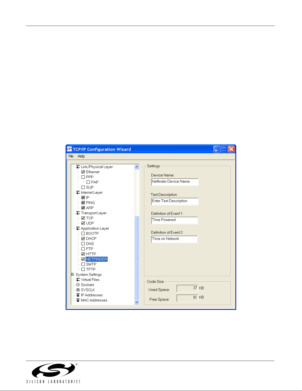
4. In the Protocol Settings section of the left window, make sure Ethernet is selected then check DHCH,
HTTP, and NETFINDER. The lower level protocols (TCP and UDP) will automatically be enabled as shown in
Figure 14.
Figure 14. TCP/IP Configuration Wizard Protocol Selection
Rev. 0.5 13
Page 14

Ethernet-DK
5. Save the selected configuration using the File→Save As menu.
6. Generate a new project with supporting firmware by selecting Generate Project from the File menu (see
Figure 9).
7. When prompted for a folder to save the project, browse to an empty directory or create a new directory.
Note: Any files in the selected directory will be overwritten. Click the OK button.
8. Click the OK button when the “Project generated successfully” message appears.
9. Close the TCP/IP Configuration Wizard.
Figure 15. TCP/IP Configuration Wizard Project Generation
14 Rev. 0.5
Page 15

Ethernet-DK
6.2.2. Programming the MCU
We will now build the project created by the TCP/IP Configuration Wizard and download the firmware to the MCU
using the Silicon Laboratories IDE.
1. From the Windows Start menu, start the Silicon Laboratories IDE. The shortcut will be under the
Start→Silicon Laboratories menu. Alternatively, the Silicon Labs IDE can be started by double-clicking
IDE.exe located by default in the “C:\SiLabs\MCU” directory.
2. After the splash screen disappears, open the generated project using the Project→Open Project menu
command. Browse to the directory where the TCP/IP project was generated. Select TCPIP_Project.wsp, and
click the Open button.
Note: An example project is available by default in the
“C:\Silabs\MCU\Examples\C8051F12x\Ethernet\HTTP\web-server-2” directory. This project is identical to the
one generated in the previous steps.
Figure 16. Opening a Project in the Silicon Labs IDE
3. If you would like to view the source code, double-click on main.c on the left hand side of the screen. Source
code modification is not required to run this demo.
4. Build the project. This can be done by clicking on the Build/Make Project button in the toolbar, selecting
Project→Build/Make Project from the menu, or pressing the F7 shortcut key.
5. Click
6. Download the project to the target by clicking the Download Code button in the toolbar.
7. Run the demo by clicking the Go button in the toolbar (
.
the
Connect
Note: If you receive the error message “Communication could not be established with the specified serial
adapter”, open the Connection Options Dialog by selecting
Verify that the
pressing the shortcut key
button in the toolbar or select
USB Debug Adapter
F5
.
is selected and that the debug interface is set to
Debug→Connect
Options→Connection Options
see Figure 11), selecting
from the menu
Debug→Go
.
from the menu.
JTAG.
from the menu, or
Figure 17. Running the Demo in the Silicon Labs IDE
Rev. 0.5 15
Page 16

Ethernet-DK
6.2.3. Finding the Embedded System
We will now search for embedded systems on the network.
1. Press the Search button as shown in Figure 18 to begin searching for devices.
Figure 18. Search Button
2. The Embedded System should appear inside a box with a green background. If it appears inside a box with a
yellow background, then a DHCP server was not found. Please skip directly to step 5.
3. Select the embedded system by clicking anywhere inside the green area. After the black border appears,
press the Web Browser Quick Launch Button.
Figure 19. Web Browser Quick Launch Button
16 Rev. 0.5
Page 17

Ethernet-DK
4. The default web browser should launch and display the home page served by the embedded web server. The
same result can be achieved by typing the IP address of the embedded web server into the address bar of a
web browser. Figure 20 shows a screenshot of the home page.
Now go directly to Section "6.3. Stage 3—Configuring MAC and IP Addresses over the Serial Port‚"
on page 20.
Figure 20. Hello World Web Page
5. If the network does not have a DHCP server, then the embedded system will search for approximately 35
seconds before going into static IP address mode. After going into static IP address mode, Netfinder will
display information about the device in a window with a yellow background. Select the device by clicking
inside the yellow area and pressing the Assign IP button as shown in Figure 21.
Figure 21. Static IP Address Mode
Rev. 0.5 17
Page 18

Ethernet-DK
6. Enter the IP address, subnet mask, and default gateway (if known) into the ‘Assign IP Address’ dialog and
press OK. See Appendix A for information on how to configure the PC with a static IP address and how to
select a static IP address for the CP2201EB. A windows command line window should appear, ping the
device at its new address, then close. Programming is successful when the progress bar stops and gives the
message “Success - Device Programmed” as shown in Figure 22.
.
Figure 22. Assign IP Address Dialog
7. Close the ‘Assign IP Address’ dialog then press Search to refresh the Netfinder screen.
8. Select the device by clicking inside the yellow area and pressing the Web Browser quick launch button
as shown in Figure 23.
Figure 23. Web Browser Quick Launch Button In Static IP Address Mode
18 Rev. 0.5
Page 19

Ethernet-DK
9. The default web browser should launch and display the home page served by the embedded web server. The
same result can be achieved by typing the IP address of the embedded web server into the address bar of a
web browser. Figure 24 shows a screenshot of the uWeb-v2.0 home page.
Figure 24. Hello World Web Page
Rev. 0.5 19
Page 20

Ethernet-DK
6.3. Stage 3—Configuring MAC and IP Addresses over the Serial Port
In the first two stages of the demo, we learned how to generate firmware for an embedded web server using the
TCP/IP Configuration Wizard and access the embedded server from a web browser. In this stage, we will learn
how to dynamically configure the IP address over the serial port.
6.3.1. Configuring the Target Board Jumpers for UART communication.
To enable UART communication on the C8051F120 Target Board, jumpers J6 and J9 must be shorted. See
Figure 31 for the location of J6 and J9.
6.3.2. Modifying the Firmware to Enable the Serial Port
The simple web server firmware generated by the TCP/IP Configuration Wizard does not support configuring the IP
address over the serial port. In order to configure the MCU using the serial port, the firmware must be modified.
The web-server-3 project in the examples folder has been created to demonstrate an example of configuration
using the serial port. The following list outlines the functionality that has been added to web-server-3:
VDD Monitor is enabled as a reset source because firmware needs to write/erase Flash memory.
UART1 Initialization routine uses Timer 1 for baud rate generation.
UART1 is assigned to P0.0 and P0.1 in the Crossbar.
The stdio.h header file is included to allow use of string formatting functions such as printf().
The ipconfig() routine is used to configure the MAC address.
The global ip_address[4] variables is added in the Scratchpad area of Flash to store the programmed MAC
Address. The Scratchpad area is used to store the variable because it can be erased and re-written without
interfering with program code.
The global first_time variable is stored in Flash to keep track of whether the IP address has been
programmed.
The following instructions show how to load the web-server-3 project:
1. Halt the MCU by clicking the Stop button in the toolbar
shortcut key
F4
.
, selecting
Debug→Stop
from the menu, or pressing the
2. Close the current open project using the Project→Close Project menu command.
3. Open the web-server-3 project using the Project→Open Project menu command. The web-server-2 project
workspace is located by default in “C:\SiLabs\MCU\Examples\Ethernet\HTTP\web-server-2” directory.
4. Build the project. This can be done by clicking on the Build/Make Project button in the toolbar, selecting
Project→Build/Make Project from the menu, or pressing the F7 shortcut key.
5. Download the project to the target by clicking the Download Code button in the toolbar.
6. Run the demo by clicking the Go button in the toolbar
shortcut key
F5
.
, selecting
Debug→Go
from the menu, or pressing the
20 Rev. 0.5
Page 21

Ethernet-DK
6.3.3. Programming the IP Address
Now the MCU will be running the new firmware and blinking the green LED (P1.6) to indicate that the IP address
has not been programmed. In this mode, the MCU is waiting for the user to initiate the update by connecting to the
serial port and pressing any key to start. Figure 25 shows the output seen on a UART terminal screen when the
MCU is waiting for user input. The following instructions show how to program the IP and MAC addresses.
1. Connect the serial port on the C8051F120 Target Board to an available COM port on the PC using a serial
cable (included in kit). If the PC does not have a COM port, a USB-to-UART bridge such as the CP210x
Evaluation Kit available at www.silabs.com can be used as a virtual COM port.
2. Open a UART terminal on the PC and configure it for 9600 Baud 8-N-1 communication.
Figure 25. Waiting for User Input
3. Once connected, you should see the text in Figure 25 appear on the screen. Press any key.
4. The MCU will prompt you to specify and verify an IP address. Figure 26 shows an example of successful
programming of the IP address.
Figure 26. Successful Programming of IP Address
5. If programming is successful, the green LED on the C8051F120 Target Board will stop blinking and the web
server will start. You should now be able to ping the embedded web server or access it from a web browser.
Note: Once programmed, the MCU will not prompt for the IP address until the next firmware download. To
force an IP address update hold the SW2 (P3.7) switch on the C8051F120 Target Board down and reset the
MCU.
Rev. 0.5 21
Page 22

Ethernet-DK
6.4. Stage 4—Adding Web Server Content
In the first three stages of the demo, we learned how to make an embedded web server, find it on the network
using Netfinder, and program its IP over the serial port. In this stage, we will learn how to change the HTML content
on the server and see an example of an embedded temperature sensing web server (uWeb) that graphs
temperature and controls an LED.
6.4.1. Modifying the Source HTML Content
The following instructions show how to modify the HTML content in the web server. You may use the example in
stage 1 or the example in stage 2 as a starting point. We will start by modifying the main web page index.html.
1. In the “VFILE” subdirectory of the main project folder, open index.html in a text editor (e.g., Notepad). Any of
the projects generated earlier can be used for this stage of the demo.
2. Modify the HTML source to make the web page noticeably different. This can include changing the
background color or the text. Figure 27 shows the text changed to “This web page has been modified”. Save
the HTML source file when done.
.
Figure 27. Modifying the HTML Source
6.4.2. Updating the File Arrays using HTML2C
All web server content is added to the project in the form of file arrays (unsigned character arrays initialized to the
binary representation of the file). The HTML2C utility reads any file (HTML, images, executable binary files, etc.)
and generates two files (original_filename.h and original_filename.c) that can be added to the project. HTML2C
can be accessed several ways including:
Drag and drop. Web server content dropped on HTML2C will initiate a conversion.
File Open command from GUI. HTML2C has a graphical user interface to start conversions.
Batch File. The update.bat batch file in the “VFILE” folder can be used to automate the conversion process.
If additional content is added to the server, the batch file can be updated as shown in Figure 28.
.
Figure 28. Automating the Conversion Using a Batch File
22 Rev. 0.5
Page 23

Ethernet-DK
6.4.3. Re-Building the Project and Viewing Results
Once the file arrays are updated, it is time to re-build the project and view the results.
1. Re-build the project. This can be done by clicking on the Build/Make Project button in the toolbar, selecting
Project→Build/Make Project from the menu, or pressing the F7 shortcut key.
2. Download the project to the target by clicking the Download Code button in the toolbar.
3. Run the server by clicking the Go button in the toolbar
shortcut key
4. View the embedded web server from a web browser using the same methods learned in stage 1 or stage 2.
5. The updated web page stored inside the MCU should be displayed on the screen as shown in Figure 29.
F5
.
, selecting
Debug→Go
from the menu, or pressing the
Figure 29. Embedded Web Server with Modified Content
6.4.4. Viewing the uWeb Embedded Web Server
The “Hello World” server used in the demo up to this point contains a single static web page. Another example
server included as a HEX file in the “Examples\C8051F12x\Ethernet\HTTP\uWeb” folder is the “uWeb” server. This
embedded web server contains multiple HTML pages, images, a Java temperature display applet, and CGI script
capabilities allowing the detection and control of an LED state. This server demonstrates some of the capabilities of
the Silicon Laboratories TCP/IP stack. The following instructions can be used to download the “uWeb” server.
1. While connected to the C8051F120 Target Board, select
2. Browse to the “Examples\C8051F12x\Ethernet\HTTP\uWeb” folder. Select the uWeb_F120_3.hex and click
Download.
3. Program the IP address using the method in Section 6.3.3 on page 21.
4. Type in the IP address of the embedded system in a web browser and press Enter. The uWeb server
executing on the MCU should be displayed on the screen as shown in Figure 30.
Debug→Download Object Code
from the menu.
Figure 30. uWeb Embedded Web Server
Rev. 0.5 23
Page 24

Ethernet-DK
7. Example Source Code
The Embedded Ethernet Development Kit includes example source code, libraries, and register definition files for
all MCU devices. These examples are installed by default in the “C:\SiLabs\MCU\Examples” directory during IDE
installation. Inside this directory an “Ethernet” folder is included within each device family directory supported by
the TCP/IP Configuration Wizard. Each of the examples is described below.
7.1. HTTP Web Server
Three HTTP Web Server examples are included by default in the
“C:\SiLabs\MCU\Examples\C8051F12x\Ethernet\HTTP” directory. These are the same examples used in the
Embedded Ethernet Demo. The first two examples web-server-1 and web-server-2 are under 4 kB and can be
compiled using the evaluation version of the Keil C51 compiler. The uWeb server example is larger than 4 kB and
requires the full version of the Keil C51 compiler to build the project. A HEX file containing the firmware object code
is available for users who do not have the full version of the Keil C51 compiler. See Section 6 on page 8 for
additional information about the HTTP examples.
7.2. SMTP Mail Client
The SMTP Mail Client example shows how to send an e-mail from the embedded system. When run, the example
will send two e-mails to the SMTP server specified by IP_SMTP_ADDR[] in mn_userconst.h. This address should
be set to the address of the SMTP server on the network. Ask your network administrator for the IP address of the
SMTP server on your network. Once the e-mails are received by the mail server, they are forwarded to e-mail
addresses specified by to[] in main.c. The messages can be received by the PC by opening a mail program such
as Outlook. One e-mail will be text based and the other will have a text file attachment.
The SMTP example is located by default in the “C:\SiLabs\MCU\Examples\C8051F12x\Ethernet\SMTP” directory.
The example can be opened by opening the project file SMTP.wsp in the Silicon Laboratories IDE.
7.3. TCP Echo Client/Server
The TCP Echo Client/Server example shows how to send and receive data using a low level TCP socket. The
same example file can configure the MCU as a client or server based on the value of SERVER_MODE in main.c. Set
SERVER_MODE to 1 for server or 0 for client.
In client mode, the embedded system sends a string to a TCP Echo server, then waits for the string to be received.
Once the string is received from the server, the embedded system repeats the process. The TCP Echo server
application “TCP_SVR.exe” should be started on the PC prior to running code on the embedded system.
In server mode, the embedded system waits for strings to be sent from the PC client application “TCP_CLI.exe”
and echoes them back to the PC. The C8051F120 Echo server should be started prior to starting the PC
application. The PC client application is started with the following syntax:
TCP_CLI 10.10.10.163 (where 10.10.10.163 is the IP Address of the embedded echo server).
The TCP Echo Client/Server example is located by default in the
“C:\SiLabs\MCU\Examples\C8051F12x\Ethernet\TCP” directory. The example can be opened by opening the
project file TCP.wsp in the Silicon Laboratories IDE.
7.4. UDP Echo Client/Server
The UDP Echo Client/Server example shows how to send and receive data using low level UDP socket. This
example is identical to the TCP example, except data is sent in UDP packets. The UDP Echo Client/Server
example is located by default in the “C:\SiLabs\MCU\Examples\C8051F12x\Ethernet\UDP” directory. The example
can be opened by opening the project file UDP.wsp in the Silicon Laboratories IDE.
7.5. DHCP/BOOTP Examples
Two HTTP web server examples using DHCP and BOOTP are provided in the "\C8051F12x\Ethernet\DHCP" and
"\C8051F12x\Ethernet\BOOTP" folders respectively. These servers dynamically obtain their IP address information
from a DHCP or BOOTP server.
24 Rev. 0.5
Page 25

Ethernet-DK
8. C8051F120 Target Board
The Embedded Ethernet Development Kit includes a target board with a C8051F120 device pre-installed for
evaluation and software development. Numerous input/output (I/O) connections are provided to facilitate
prototyping using the target board. Refer to Figure 31 for the locations of the various I/O connectors. For further
details, see the “C8051F12x Development Kit User’s Guide” located on the kit CD or installed by default in the
“C:\SiLabs\MCU\Documentation\Users Guides” directory.
P1 Power connector (accepts input from 7 to 15 VDC unregulated power adapter)
J1 Connects SW2 to P3.7 pin
J3 Connects LED D3 to P1.6 pin
J4 JTAG connector for Debug Adapter interface
J5 DB-9 connector for UART0 RS232 interface
J6 Connector for UART0 TX (P0.0)
J8 Connector for UART0 RTS (P4.0)
J9 Connector for UART0 RX (P0.1)
J10 Connector for UART0 CTS (P4.1)
J11 Analog loopback connector
J12–J19 Port 0–7 connectors
J20 Analog I/O terminal block
J22 VREF connector
J23 VDD Monitor Disable
J24 96-pin Expansion I/O connector
R1 Current Limiting Resistor For 96-pin Interface.
Note: R1 should be shorted with a zero ohm resistor if the 'F120TB is providing power to the AB4.
J24
Port 4
Pin 2
Pin 1
J20
Port 3Port 6Port 5
Pin 2
Pin 1
Port 7
Port 0 Port 2
C8051
F12X
J11
Pin 1
J22
Pin 1
Port 1
J23
Pin 1
Pin 2
Figure 31. C8051F120 Target Board
J3
PWR
J8J10
P1.6
J1
R1
J5
J9J6
RESET
P3.7
J4
P1
JTAG
Pin 1
Rev. 0.5 25
Page 26

Ethernet-DK
8.1. C8051F120 Target Board Schematic
26 Rev. 0.5
Figure 32. C8051F120 Target Board Schematic
Page 27

Ethernet-DK
9. AB4 Ethernet Development Board
The Embedded Ethernet Development Kit includes the AB4 Ethernet Development Board designed to connect the
C8051F120 (or C8051F340, C8051F020, C8051F040, or C8051F060) target board to an ethernet network. The
ethernet controller used is the CP2200. Refer to Figure 33 for the locations of the various I/O connectors.
P1 96-pin Expansion I/O connector
U1 CP2200 Ethernet Controller
J1 RJ-45 Ethernet Connector
SW1, SW2 Input Switches
LED1, LED2 Output LEDs
J4 Disconnects SW2 from P1
J3 Disconnects SW1 from P1
J5 Disconnects LED1 from P1
J6 Disconnects LED2 from P1
SW2 SW1
LED1
LED2
Prototyping
Area
RJ45
J6
J5
J3
J4
CP2200
AB4 Ethernet Development Board
Figure 33. AB4 Ethernet Development Board
The AB4 Ethernet development board is compatible with multiple MCU development boards that contain a 96-pin
connector. Table 2 maps select signals on the AB4 board to the corresponding MCU port pin(s).
Table 2. AB4 Board Signals
AB4 Signal Name F020, F040, & F120 F060 F340
SW1 P2.0/P4.1 P2.0 P1.1
SW2 P2.1/P4.2 P2.1 P1.2
LED1 P2.2/P4.3 P2.2 P1.3
LED2 P2.3/P4.4 P2.3 P1.4
INT
RST
A15_CS
P2.4/P0.3 P2.4/P0.3 P0.3
P4.5 P4.5 P1.0
P5.7 P5.7 P2.7
Rev. 0.5 27
Page 28

Ethernet-DK
9.1. Expansion I/O Connector (J1)
The 96-pin expansion I/O connector J1 is used to connect the AB4 Ethernet Development Board to the C8051F120
Target Board. J1 provides access to many C8051F120 signal pins. Pins for +3 V, digital ground, analog ground and
the unregulated power supply (VUNREG) are also available. The VUNREG pin is connected directly to the
unregulated +V pin of the P1 power connector on the C8051F120 Target Board. See Table 3 for a complete list of
pins available at J1.
Table 3. J1 Pin Descriptions
Pin # Description Pin # Description Pin # Description
A-1 +3 VD2 (+3.3 VDC) B-1 DGND (Digital Gnd) C-1 XTAL1
A-2 MONEN B-2 P1.7 C-2 P1.6
A-3 P1.5 B-3 P1.4 C-3 P1.3
A-4 P1.2 B-4 P1.1 C-4 P1.0
A-5 P2.7 B-5 P2.6 C-5 P2.5
A-6 P2.4 B-6 P2.3 C-6 P2.2
A-7 P2.1 B-7 P2.0 C-7 P3.7
A-8 P3.6 B-8 P3.5 C-8 P3.4
A-9 P3.3 B-9 P3.2 C-9 P3.1
A-10 P3.0 B-10 P0.7 C-10 P0.6
A-11 P0.5 B-11 P0.4 C-11 P0.3
A-12 P0.2 B-12 P0.1 C-12 P0.0
A-13 P7.7 B-13 P7.6 C-13 P7.5
A-14 P7.4 B-14 P7.3 C-14 P7.2
A-15 P7.1 B-15 P7.0 C-15 P6.7
A-16 P6.6 B-16 P6.5 C-16 P6.4
A-17 P6.3 B-17 P6.2 C-17 P6.1
A-18 P6.0 B-18 P5.7 C-18 P5.6
A-19 P5.5 B-19 P5.4 C-19 P5.3
A-20 P5.2 B-20 P5.1 C-20 P5.0
A-21 P4.7 B-21 P4.6 C-21 P4.5
A-22 P4.4 B-22 P4.3 C-22 P4.2
A-23 P4.1 B-23 P4.0 C-23 TMS
A-24 TCK B-24 TDI C-24 TDO
A-25 /RST B-25 DGND (Digital Gnd) C-25 VUNREG
A-26 AGND (Analog Gnd) B-26 DAC1 C-26 DAC0
A-27 CP1- B-27 CP1+ C-27 CP0A-28 CP0+ B-28 VREF C-28 VREFD
A-29 VREF0 B-29 VREF1 C-29 AIN0.7
A-30 AIN0.6 B-30 AIN0.5 C-30 AIN0.4
A-31 AIN0.3 B-31 AIN0.2 C-31 AIN0.1
A-32 AIN0.0 B-32 AGND (Analog Gnd) C-32 AV+ (+3.3 VDC Analog)
28 Rev. 0.5
Page 29

9.2. AB4 Board Schematic
Ethernet-DK
Rev. 0.5 29
Page 30

Ethernet-DK
10. Silicon Laboratories IDE (Integrated Development Environment)
The Silicon Laboratories IDE integrates a source-code editor, source-level debugger and in-system Flash
programmer. The use of third-party compilers and assemblers is also supported. This development kit includes the
Keil Software A51 macro assembler, BL51 linker, and evaluation version of the C51 compiler. These tools can be
used from within the Silicon Laboratories IDE.
10.1. System Requirements
The Silicon Laboratories IDE requirements:
Pentium-class host PC running Microsoft
One available USB port.
64 MB RAM and 40 MB free HD space recommended.
10.2. Assembler and Linker
A full-version Keil A51 macro assembler and BL51 banking linker are included with the development kit and are
installed during IDE installation. The complete assembler and linker reference manual (A51.pdf) can be found online under the Help menu in the IDE or in the “SiLabs\MCU\hlp” directory.
10.3. Evaluation C51 C Compiler
An evaluation version of the Keil C51 C compiler is included with the development kit and is installed during IDE
installation. The evaluation version of the C51 compiler is the same as the full professional version except code
size is limited to 4 kB and the floating point library is not included. The TCP/IP Library object code does not count
against the 4 kB code size limit. The C51 compiler reference manual (C51.pdf) can be found under the Help menu
in the IDE or in the “SiLabs\MCU\hlp” directory.
®
Windows 2000/XP or later.
10.4. Using the Keil Software 8051 Tools with the Silicon Laboratories IDE
The default configuration of the Keil 8051 tools when using the Silicon Laboratories IDE project manager enables
object extensions, debug record generation, and uses the OMF-51 format. This is required for source level
debugging. The Silicon Labs IDE also allows the Keil 8051 tools to be called directly from the command line using
a batch file.
“SiLabs\MCU\Documentation\Appnotes” directory on the CD-ROM for additional information on using the Keil 8051
tools with the Silicon Laboratories IDE.
Refer to Application Note “AN104:
Integrating Keil 8051 Tools Into the Silicon Labs IDE”
in the
30 Rev. 0.5
Page 31

Ethernet-DK
APPENDIX—SUPPORTED PROTOCOLS
Link/Physical Layer:
Ethernet (IEEE802.3)—Widely installed local area network link/physical layer.
Internet Layer:
IP (Internet Protocol)—IP specifies the format of packets and manages the addressing of all devices on the
network. IP is included in all builds of the TCP/IP stack.
PING (Packet Internet Groper)—PING is a basic network program which verifies that a particular IP address
exists and can respond to requests. PING is included in all builds of the TCP/IP stack.
ARP (Address Resolution Protocol)—ARP converts higher-level IP addresses to lower-level MAC addresses. It
is not available with SLIP or PPP.
Transport Layer:
TCP (Transmission Control Protocol)—TCP is a connection-oriented transport protocol. It offers a reliable, full-
duplex data stream that may be written to and read from by devices on the network.
UDP (User Datagram Protocol)—UDP is a connection free, best effort transport protocol. It formats data into units
called datagrams and sends them across the network; however, it provides no guarantee that the data will arrive. A
UDP checksum is performed on the data to allow the receiving node the ability to detect data errors.
Application Layer:
DHCP (Dynamic Host Configuration Protocol)—Used to obtain a dynamic IP address from a DHCP server.
BOOTP (Bootstrap Protocol)—Older protocol used to obtain a dynamic IP address.
FTP (File Transfer Protocol)—FTP transfers a complete file from one network device to another. FTP requires the
TCP transport layer. The FTP module in the TCP/IP stack configures the device to operate as an FTP server only.
It cannot act as an FTP client.
HTTP (HyperText Transfer Protocol)—HTTP sends and requests files (typically HTML files) across a network. It
is commonly used to transfer files across the World Wide Web. HTTP requires the TCP transport layer. The HTTP
module in the TCP/IP stack configures the device to operate as an HTTP server only. It cannot act as an HTTP
client or browser.
SMTP (Simple Mail Transfer Protocol)—SMTP sends and receives e-mails. It requires the TCP transport layer.
The SMTP module in the TCP/IP stack can only act as an SMTP client. An SMTP server must be available on the
network to forward emails from the Ethernet-DK to the specified e-mail address.
TFTP (Trivial File Transfer Protocol)—TFTP is a simplified version of FTP. It requires the UDP transport layer.
The TFTP module in the TCP/IP stack can only act as a TFTP client. It cannot act as a TFTP server.
DNS (Domain Name Service) -- Allows domain name (e.g. www.silabs.com) to be resolved into an equivalent IP
address.
Netfinder -- Allows an embedded system to be identified on a network.
Rev. 0.5 31
Page 32

Ethernet-DK
DOCUMENT CHANGE LIST
Revision 0.3 to Revision 0.4
Added Netfinder Example.
Added note that R1 should be shorted with a zero ohm resistor on the 'F12x Target Board.
Updated the supported protocols in the Appendix.
Updated screenshots for Version 3.1 of the TCP/IP Configuration Wizard.
Revision 0.4 to Revision 0.5
Removed Section 10. USB Debug Adapter. See USB Debug Adapter User's Guide.
32 Rev. 0.5
Page 33

NOTES:
Ethernet-DK
Rev. 0.5 33
Page 34

Ethernet-DK
CONTACT INFORMATION
Silicon Laboratories Inc.
4635 Boston Lane
Austin, TX 78735
Email: MCUinfo@silabs.com
Internet: www.silabs.com
.
The information in this document is believed to be accurate in all respects at the time of publication but is subject to change without notice.
Silicon Laboratories assumes no responsibility for errors and omissions, and disclaims responsibility for any consequences resulting from
the use of information included herein. Additionally, Silicon Laboratories assumes no responsibility for the functioning of undescribed features
or parameters. Silicon Laboratories reserves the right to make changes without further notice. Silicon Laboratories makes no warranty, representation or guarantee regarding the suitability of its products for any particular purpose, nor does Silicon Laboratories assume any liability
arising out of the application or use of any product or circuit, and specifically disclaims any and all liability, including without limitation consequential or incidental damages. Silicon Laboratories products are not designed, intended, or authorized for use in applications intended to
support or sustain life, or for any other application in which the failure of the Silicon Laboratories product could create a situation where personal injury or death may occur. Should Buyer purchase or use Silicon Laboratories products for any such unintended or unauthorized application, Buyer shall indemnify and hold Silicon Laboratories harmless against all claims and damages.
Silicon Laboratories and Silicon Labs are trademarks of Silicon Laboratories Inc.
Other products or brandnames mentioned herein are trademarks or registered trademarks of their respective holders.
34 Rev. 0.5
 Loading...