

CP2201-EK
CP2201EK USER’S GUIDE
1. Kit Contents
The CP2201 Evaluation kit contains the following items:
• CP2201 Embedded Ethernet Evaluation Board (CP2201EB)
• Silicon Laboratories Embedded Ethernet Evaluation Kit CD-ROM. CD content includes:
• CP2201EK User’s Guide (this document)
• Netfinder Utility
• Firmware Image for use with the Ethernet Bootloader
• C8051F34x and CP220x Data Sheets
• Universal 9 V DC Power Supply
• Straight Through Cat5e Ethernet Cable (Blue)
• Crossover Cat5e Ethernet Cable (Yellow)
• CP2201EK Quick Start Guide
2. CP2201EK Overview
The purpose of the CP2201EK is to provide a way to easily evaluate Silicon Laboratories Ethernet Solutions and
view some of the applications made possible by the CP2200/1. To develop embedded applications using the
CP2200/1, we offer a complete Embedded Ethernet Development Kit (Ethernet-DK). The Embedded Ethernet
Development Kit contains a TCP/IP Configuration Wizard that automatically generates code to perform many of the
functions in the CP2201EK. Numerous code and application examples are also provided in the development kit.
The CP2201EK is a fully contained evaluation board. The main system controller, which runs the TCP/IP Stack and
performs other system tasks, is a 50 MIPS Silicon Laboratories C8051F340. The Ethernet controller providing
network connectivity is the Silicon Laboratories CP2201—the industry’s smallest Ethernet controller. The third
major component on the board is the Ethernet connector (RJ-45) with integrated magnetics and LEDs.
On the software side, the C8051F340 is running the CMX Micronet Web Server. The embedded web server has
web pages for displaying temperature and light sensor data, controlling the yellow LED state, sending an e-mail,
remotely updating firmware, and displaying images and CP2201 Key Features. The embedded system can also be
accessed through a command line Telnet interface.
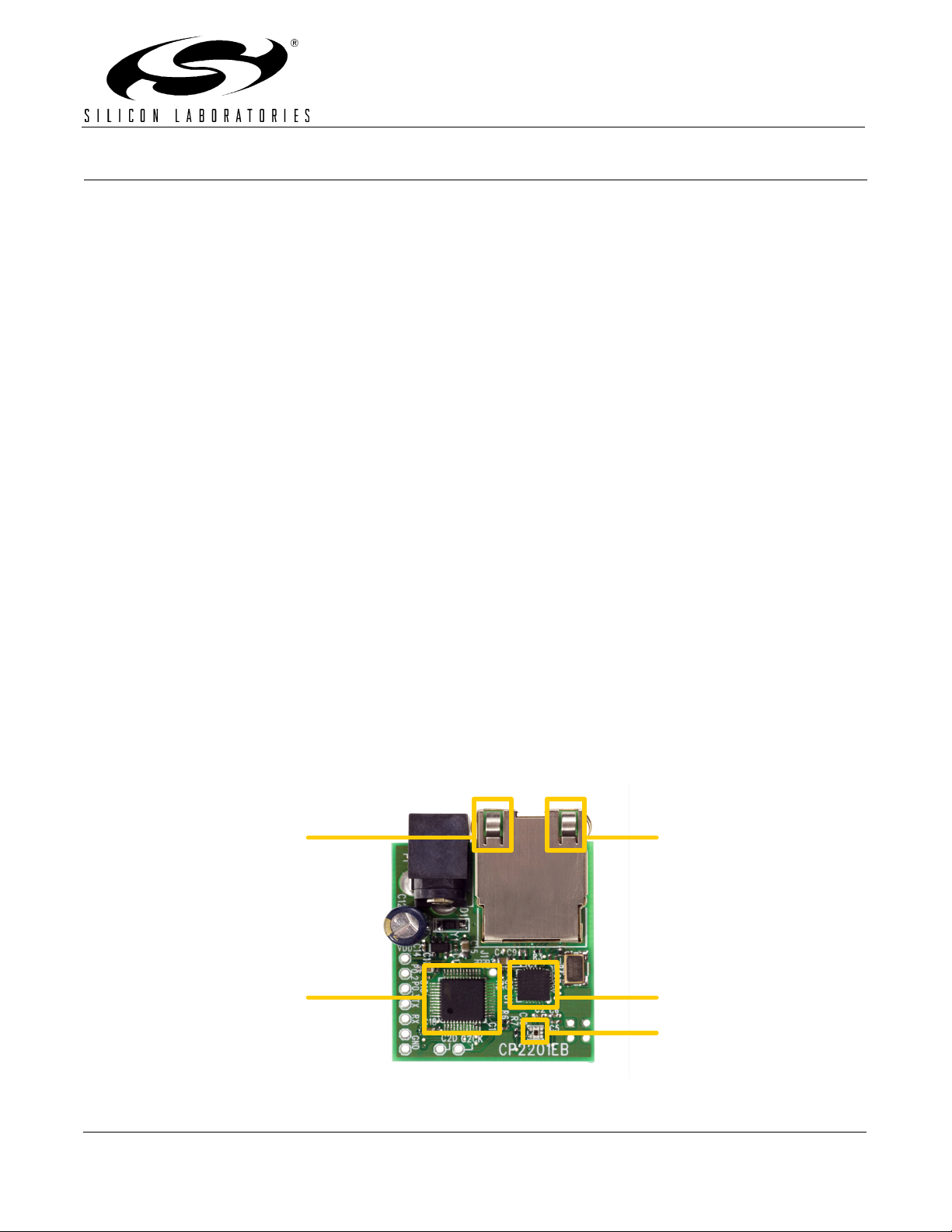
Figure 1 shows the CP2201EB and identifies its various components.
Yellow LED
System State
Green LED
Link/Activity
C8051F340
MCU w/ on-chip
Temperature
Sensor
CP2201
Ethernet
Controller
Light Sensor
Figure 1. CP2201 Evaluation Board
Rev. 0.1 2/06 Copyright © 2006 by Silicon Laboratories CP2201-EK
CP2201-EK
3. Hardware Setup
The only external hardware connections required by the CP2201EB are power and a connection to a network. All
required system configuration is performed over the network, saving the board space and cost of an LCD screen or
dedicated UART interface.
1. Connect the CP2201EB to an unused Ethernet jack using the
wall outlet or an empty port on a network router or switch. If an Ethernet outlet is not available, the CP2201
can be directly connected to a PC using the
See Appendix A for additional setup instructions if using a crossover cable.
2. Power the CP2201EB using the universal power adapter supplied with the kit.
3. Wait until the yellow LED turns to solid yellow (not blinking), stops blinking (always on), or starts to blink
intermittently (blink twice then pause).
yellow
crossover cable.
4. Software Setup
The included CD-ROM contains all CP2201EK documentation, the Netfinder utility, and a firmware image that can
be used for evaluating the Ethernet bootloader. To get started, insert the CD-ROM into your PC’s CD-ROM drive
and click “Netfinder.” Follow the on-screen instructions when the blue dialog automatically launches. If the dialog
does not automatically appear on the screen when you insert the CD-ROM, run autorun.exe found in the root
directory of the CD-ROM.
5. Network Setup
blue
straight-through cable. This can be a
The CP2201EK software uses the Netfinder utility to find all CP2201EB boards connected to the network. If the
network has a DHCP server, then each device will automatically acquire an IP address once it detects that it has
been plugged into a live network. If there are multiple CP2201EB boards on the network, the Netfinder utility allows
the user to identify the desired device based on the time powered, time plugged into network, MAC address, or IP
address.
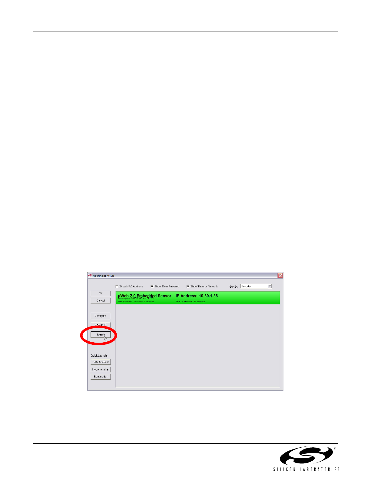
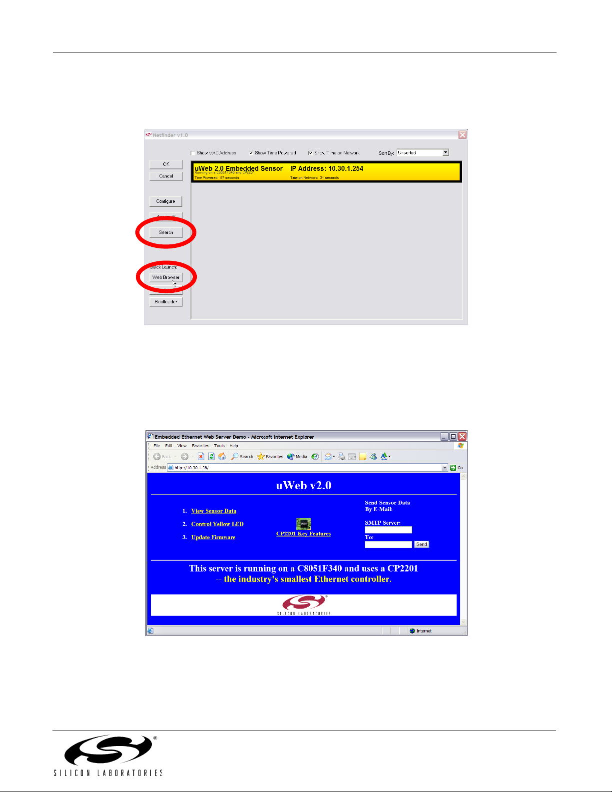
1. Press the
Search
button as shown in Figure 2 to begin searching for devices.
Figure 2. Search Button
2 Rev. 0.1
CP2201-EK
2. If the CP2201EB was able to automatically obtain an IP address through DHCP, then its IP address will
appear inside a window with green background. If the device’s IP address is 0.0.0.1 and the window background is yellow, then skip this step and the following step. If the device was unable to automatically obtain
an IP address through DHCP, then its IP address will be 0.0.0.1 and it will appear inside a window with a
yellow background.
a. If the device appears in a yellow window, then go to step 4.
b. If the device appears in a green window, then click anywhere in the green window.
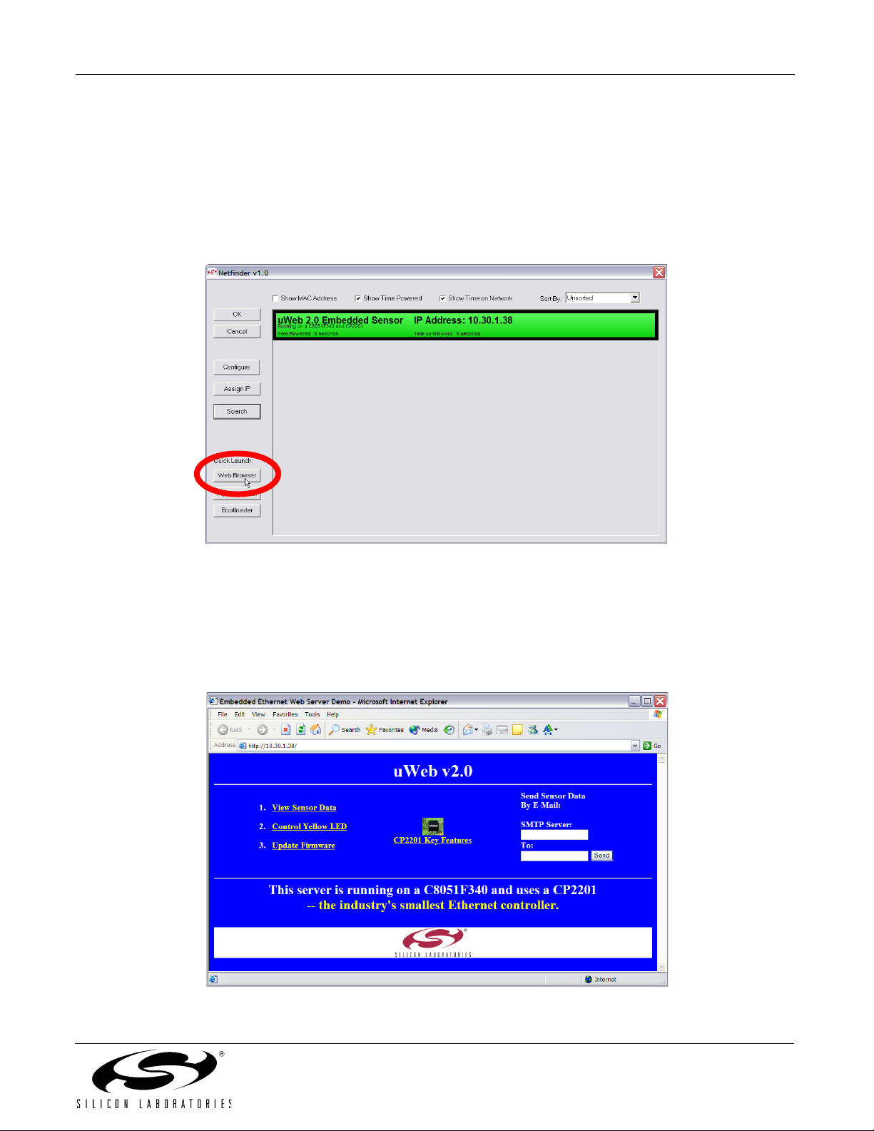
c. After the black border appears, press the Web Browser Quick Launch Button.
Figure 3. Web Browser Quick Launch Button
3. The default web browser should launch and display the home page served by the embedded web server.
The same result can be achieved by typing the IP address of the embedded web server into the address
bar of a web browser. Figure 4 shows a screenshot of the uWeb-v2.0 home page.
4. Now go directly to Section "CP2201 Evaluation Kit Demo‚" on page 6.
Figure 4. uWeb-v2.0 Home Page
Rev. 0.1 3
CP2201-EK
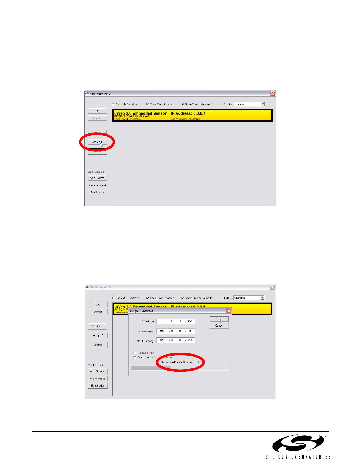
5. If the network does not have a DHCP server, then the CP2201EB will search for approximately 35 seconds
before going into static IP address mode. While searching, the yellow led will be blinking fast. After going
into static IP address mode, Netfinder will display information about the device in a window with a yellow
background. Select the device by clicking inside the yellow area and pressing the Assign IP button as
shown in Figure 5.
Figure 5. Static IP Address Mode
6. Enter the IP address, subnet mask, and default gateway (if known) into the ‘Assign IP Address’ dialog and
press OK. See Appendix A for information on how to configure the PC with a static IP address and how to
select a static IP address for the CP2201EB. A windows command line window should appear, ping the
device at its new address, then close. Programming is successful when the progress bar stops and gives
.
the message “Success - Device Programmed” as shown in Figure 6.
Figure 6. Assign IP Address Dialog
4 Rev. 0.1
CP2201-EK
7. Close the ‘Assign IP Address’ dialog then press Search to refresh the Netfinder screen. Select the device
by clicking inside the yellow area and pressing the Web Browser quick launch button as shown in
Figure 7.
Figure 7. Web Browser Quick Launch Button In Static IP Address Mode
8. The default web browser should launch and display the home page served by the embedded web server.
The same result can be achieved by typing the IP address of the embedded web server into the address
bar of a web browser. Figure 8 shows a screenshot of the uWeb-v2.0 home page.
Figure 8. uWeb-v2.0 Home Page
Rev. 0.1 5

CP2201-EK
6. CP2201 Evaluation Kit Demo
The CP2201EK demo includes:
Monitoring real-time sensor data using a web browser.
Controlling the state of the yellow LED from a web browser.
Sending an e-mail containing the latest sensor data.
Monitoring real-time sensor data using the Telnet interface.
Remotely updating firmware using the bootloader.
6.1. Monitoring Real-Time Sensor Data Using a Web Browser
Clicking the first link on the main web page ‘1. View sensor data’ will load the embedded sensor data web page
shown in Figure 8. This page alternates between refreshing the temperature and the light sensor data every two
seconds. The temperature measurements are taken from the C8051F340’s on-chip temperature sensor and the
ambient light reading is taken from the light sensor in the bottom right hand side of the board centered above the
“CP2201EB” label.
Figure 9. Viewing Sensor Data
6.2. Controlling the State of the Yellow LED Simulating Yellow/System Status LED From a Web Browser
The yellow LED on the Ethernet connector is used to indicate system status when first connecting the CP2201EB
to a network.Table 1 describes the system states indicated by the yellow LED.
Table 1. Yellow LED States
LED State System State
Blinking (slow) The MCU is waiting for a network connection. The Ethernet cable is not connected.
Blinking (fast) The MCU is connected to a network and is trying to acquire an IP address using DHCP.
On (continuous) The system has obtained an IP address and is properly configured.
Blinking (intermittent) The system has entered static IP address mode. Please use Netfinder to assign a static
IP address or cycle power to continue searching for a DHCP server.
Off (continuous) A hardware error has occurred. Please cycle power.
6 Rev. 0.1

CP2201-EK
Clicking the second link on the main web page ‘2. Control Yellow LED’ will load the yellow LED control page shown
in Figure 10. Each of the links numbered 1 through 4 on this page borrow the yellow LED for 10 seconds and force
it to the state described in the text. The yellow LED state is restored after 10 seconds or if the 5th link ‘5. Restore
LED State’ is pressed. When finished going through the various LED states, click the ‘Home’ link to return to the
main page.
Figure 10. Yellow LED Control Page
6.3. Sending an E-mail Containing the Latest Sensor Data
To send an e-mail, the two pieces of information needed are the address of an SMTP server and the destination email address. This information can be entered in the HTML form on the main web page as shown in Figure 11. On
most networks, the SMTP server can be located by typing “ping mail” at the command prompt or asking a
system administrator. If the SMTP server address is unknown, a free software SMTP server that turns any
Windows PC into an outgoing mail server is available for download from http://www.gatecomm.com. Once the
software SMTP is running, use the PC’s IP address as the SMTP server address. The SMTP server address
cannot contain any letters—only numbers are permitted. The destination e-mail address must be less than 50
characters.
Figure 11. HTML Form Used For Sending E-Mail
Rev. 0.1 7

CP2201-EK
6.4. Monitoring Real Time Sensor Data Using the Telnet Interface
The temperature and light sensor data can be monitored using the command line Telnet interface. The Telnet
interface is very similar to UART, except bytes are sent over a TCP connection instead of an RS-232 cable.
1. If Hyperterminal is not the default telnet client on your PC, then start it using START-> All Programs ->
Accessories -> Communication -> HyperTerminal. Otherwise, skip to step 4.
2. The first time you run the program, you will be prompted to enter your area code. Enter the required information and press Next or Cancel to continue.
3. When the ‘Connection Description’ Dialog appears, press Cancel, then exit from the application. Hyperterminal is now configured on your PC.
4. From Netfinder, select an embedded system and press the Hyperterminal quick launch button as shown
in Figure 12. This button initiates a Telnet connection with the selected CP2201EB using the default Telnet
client on your PC.
Figure 12. Initiating a Telnet Connection From Netfinder
Figure 13 shows a screenshot of the Telnet connection to the CP2201EB. Pressing the S key starts printing and
updating samples on the screen. Pressing the P key pauses the updates. A key difference between this method of
accessing sensor data and the web browser is that the MCU initiates updates of the information on the screen. In a
web browser, the browser must request data from the MCU. Note: The Telnet demo has been configured with a
fast update rate. We recommend closing the Telnet connection when finished viewing data to free system
resources for other parts of the demo.
Figure 13. Telnet Interface
8 Rev. 0.1

CP2201-EK
6.5. Remotely Updating Firmware Using the Bootloader
The CP2201EB has a bootloader that can be used to update its firmware over the network. The bootloader uses
the Trivial File Transfer Protocol (TFTP) to transfer an image file from the PC (TFTP Client) to the CP2201EB
(TFTP Server). The transfer must be binary and the file name in the CP2201EB’s file system must be “boot.img”.
1. Open the main web page for the CP2201EB in a web browser and click on the third link ‘3. Update Firmware.’ You should see a message saying that the server will no longer respond and that the bootloader will
shut down in 5 seconds.
2. Wait 5–10 seconds, then the CP2201EB should appear in yellow with a text description “Firmware Boot-
loader” as shown in Figure 14. Note: If the embedded system does not appear inside a yellow win-
dow, then keep searching until you see a yellow window with the title 'CP2201 Demo Board'.
Figure 14. Searching for the CP2201EB in Bootload Mode
3. Press the Bootloader quick launch button. When prompted, browse for the .img file containing the latest
firmware image and press OK. Note: Network drive paths beginning in “\\” cannot be used. An image
named CP2201EB_MFG2A.img can be found on the CD.
4. Once the image location is specified, the command line TFTP client (standard on all Windows PCs) is
launched and bootloading initiates. After 10 to 15 seconds, a confirmation message will appear on the
screen. Figure 15 shows an example of a confirmation message following a successful firmware update.
Figure 15. Successful Firmware Update
Rev. 0.1 9

CP2201-EK
APPENDIX A—USING A CROSSOVER CABLE
The CP2201EB can be connected to an Ethernet network using a standard Ethernet cable (see Figure 16) or
directly to a PC using a crossover cable (see Figure 17). Table 2 describes the benefits of using each of the
connection methods. A standard Ethernet cable is included in the kit and crossover cables are available for order
from the Silicon Laboratories website, at www.silabs.com.
Table 2. Ethernet Cable Comparison
Standard Cable Crossover Cable
Remote access to embedded system. Distance from PC to embedded system is limited by
the length of the cable.
Multiple embedded systems may be networked and
accessed from the same (or multiple) PC(s).
Shared communication medium. System may experience packet delays under heavy network traffic. This
Only a single embedded system may be accessed
from a single PC.
Dedicated channel bandwidth. Good for achieving
consistent data throughput measurements.
effect is greatly reduced if using a switched network.
An existing network with wall outlet or a router/switch is
No additional hardware required.
required.
PC does not require any additional IP address configuration.
PC must be configured with a static IP address in
order to recognize embedded system.
Standard cable is included in evaluation kit. Crossover cable is included in evaluation kit.
PC
Ethernet
Connector
Ethernet
Cable
Ethernet
Router/
Switch
Or
Wall Outlet
Ethernet
Cable
CP2201EB
Ethernet
Connector
Figure 16. Embedded Ethernet Network Connection (Standard Cable)
PC
Ethernet Crossover Cable
Ethernet
Connector
Figure 17. Embedded Ethernet Network Connection (Crossover Cable)
10 Rev. 0.1
C2201EB
Ethernet
Connector

CP2201-EK
PC Configuration
Configure the PC to have a static IP address. The steps below show how to configure a Windows PC to use a static
IP address.
1. Open the Network Connections Folder. This is accessible from the control panel or from the start menu by
right-clicking on My Network Places and selecting Properties.
2. Right-click on the Local Area Connection and select Properties.
3. Select Internet Protocol (TCP/IP) and click Properties. Optionally, if the Show icon in notification area when
connected is checked, right-clicking the system tray icon will provide a quick shortcut to the LAN properties
dialog and can be used as an indicator that the network is functioning properly.
Figure 18. Internet Protocol Properties Window
4. Select Use the following IP address and specify an IP address and subnet mask for the PC. For a subnet
mask of 255.255.255.0, the embedded system’s IP address must match the first three octets of the PC’s IP
address for the PC to recognize the embedded system. See Section for additional information about
choosing the embedded system’s IP address.
Note: When entering an IP or subnet address into the dialog box, the cursor will automatically advance to
the next field for a three digit octet. If entering a one or two digit octet, the spacebar, right arrow key, or ‘.’
can be pressed to advance to the next field.
Figure 19. IP Address and Subnet Mask Window
5. Click OK after the static IP address and subnet mask have been configured. The PC will now be able to
access the embedded system using a crossover cable.
Rev. 0.1 11

CP2201-EK
Selecting an IP Address for the Embedded System
For a PC to recognize an embedded system on a network, its IP address and subnet mask need to be configured.
Below are a few guidelines to follow when choosing an IP address for the embedded system. Figure 20 shows an
example of a compatible PC and embedded system IP address combination.
1. Find the IP address and Subnet mask for the PC. If a Default Gateway is specified, then save this address
for later use. If you are using a crossover cable, you may choose any IP address for your PC as long as the
Subnet mask allows it to recognize the embedded system.
2. The IP address chosen for the embedded system must match the PC’s IP address in all bit locations where
the Subnet mask is a 1 in order for the PC to recognize the embedded system. Otherwise, the PC will send
it’s request outside the local network.
3. Do not duplicate IP addresses or select a broadcast address. An IP address is considered a broadcast
address if all bits which are 0 in the Subnet mask are 1 in the IP address. Broadcast addresses with additional 1s such as 10.10.255.255 (Figure 20) can be broadcast to nodes outside the local network.
4. The address 255.255.255.255 is known as the Ethernet broadcast address and is used when the Subnet
mask for the network is not known. Any packet transmitted to this address will reach all nodes on the local
network but cannot go further than the nearest router.
IP Address Selection Example
The example in Figure 20 shows the IP address and subnet mask of the PC we want to connect to the embedded
system. Since the first 24 bits of the subnet mask are 1, the first 24 bits of the embedded web server’s IP address
(shown in bold) must match the PC’s IP address. Only the least significant 8 bits may vary making the valid range
of IP addresses for the embedded web server 10.10.10.0 to 10.10.10.254 with the exception of 10.10.10.80 since
this address is already taken by the PC. 10.10.10.255 is reserved because it is the broadcast address for this
network.
PC IP Address
PC Subnet Mask
10 10 10 80
0000 1010 0000 1010 0000 1010 0101 0000
255 255 255 0
1111 1111 1111 1111 1111 1111 0000 0000
Embedded Web Server IP Address
10
10
0000 1010 0000 1010 0000 1010
163
10
1010 0011
(decimal)
(binary)
(decimal)
(binary)
(decimal)
(binary)
Figure 20. IP Address Selection Example
12 Rev. 0.1

APPENDIX B—SCHEMATIC
CP2201-EK
Rev. 0.1 13

CP2201-EK
CONTACT INFORMATION
Silicon Laboratories Inc.
4635 Boston Lane
Austin, TX 78735
Email: MCUinfo@silabs.com
Internet: www.silabs.com
The information in this document is believed to be accurate in all respects at the time of publication but is subject to change without notice.
Silicon Laboratories assumes no responsibility for errors and omissions, and disclaims responsibility for any consequences resulting from
the use of information included herein. Additionally, Silicon Laboratories assumes no responsibility for the functioning of undescribed features
or parameters. Silicon Laboratories reserves the right to make changes without further notice. Silicon Laboratories makes no warranty, representation or guarantee regarding the suitability of its products for any particular purpose, nor does Silicon Laboratories assume any liability
arising out of the application or use of any product or circuit, and specifically disclaims any and all liability, including without limitation consequential or incidental damages. Silicon Laboratories products are not designed, intended, or authorized for use in applications intended to
support or sustain life, or for any other application in which the failure of the Silicon Laboratories product could create a situation where personal injury or death may occur. Should Buyer purchase or use Silicon Laboratories products for any such unintended or unauthorized application, Buyer shall indemnify and hold Silicon Laboratories harmless against all claims and damages.
Silicon Laboratories and Silicon Labs are trademarks of Silicon Laboratories Inc.
Other products or brandnames mentioned herein are trademarks or registered trademarks of their respective holders.
14 Rev. 0.1
 Loading...