

Page 1
Biometric EXP EVB UG
BIOMETRIC EXP Evaluation Board USER’S GUIDE
1. Introduction
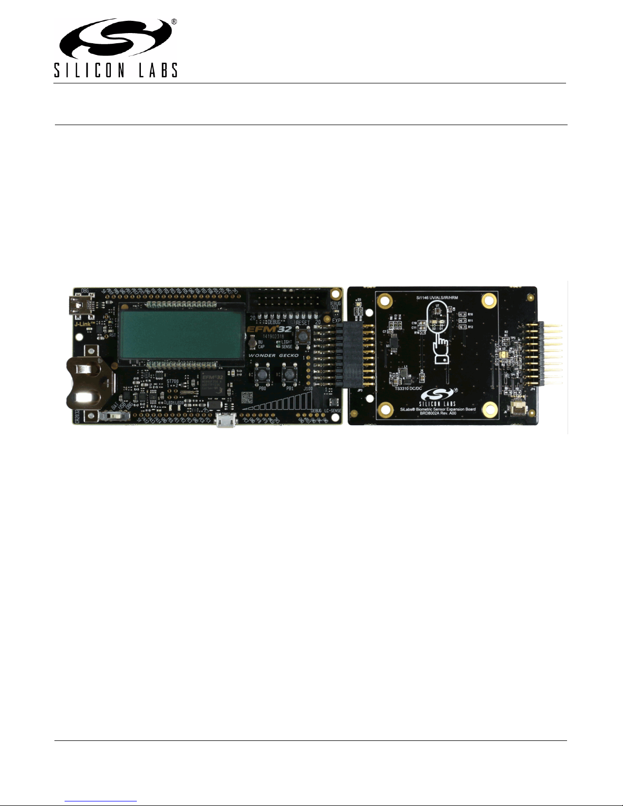
The Silicon Laboratories’ Biometric-EXP Evaluation Board is a hardware plugin card for EFM32™ Starter Kits
(STK’s). The Biometric-EXP is intended to demonstrate and evaluate the biometric applications of Silicon
Laboratories Si7013 Humidity and Temperature Sensor and the Si1146 Proximit y/UV/Ambient Light Sensor which
is capable of monitoring pulse rate and oxygen saturation (SpO2). A Biometric-EXP Software Demo is available to
download to an EFM32 Wonder Gecko STK through Simplicity Studio. The software is capable of displaying
humidity, temperature, UV, pulse rat e, and SpO2 readings on the Wonder Gecko STK display. In addition to the
Silicon Labs sensors, it is also of note that the Biometric-EXP EVB contains a Silicon Laboratories’ TS3310 Boost
DC-DC Converter.
Figure 1. EFM32 Wonder Gecko STK (Left) Connected to a Biometric-EXP (Right)
1.1. Key Features
Si7013 Humidity and Temperature Sensor
Si1146 Proximity/UV/Ambient Light Sensor capable of monitoring Pulse Rate and SpO2
6-pin ribbon cable connector for attaching a wrist-based heart rate monitor EVB (ordered separately as
HRM-GGG-PS)
20-pin expansion header
Battery operated with low power optimizations for long battery life
Demonstration software source code available
USB debug mode allowing HRM and SpO2 samples to be transferred to a PC
Windows GUI to visualize pulse signals and to record samples from USB debug mode
Easy use through Simplicity Studio
Rev. 0.1 8/14 Copyright © 2014 by Silicon Laboratories Biometric EXP EVB UG
Page 2
Biometric EXP EVB UG
2. Loading the Demo onto the Wonder Gecko STK
The following steps will load the demo firmware onto the Wonder Gecko STK. This process requires Simplicity
Studio which is available for download at www.silabs.com/simplicity-studio.
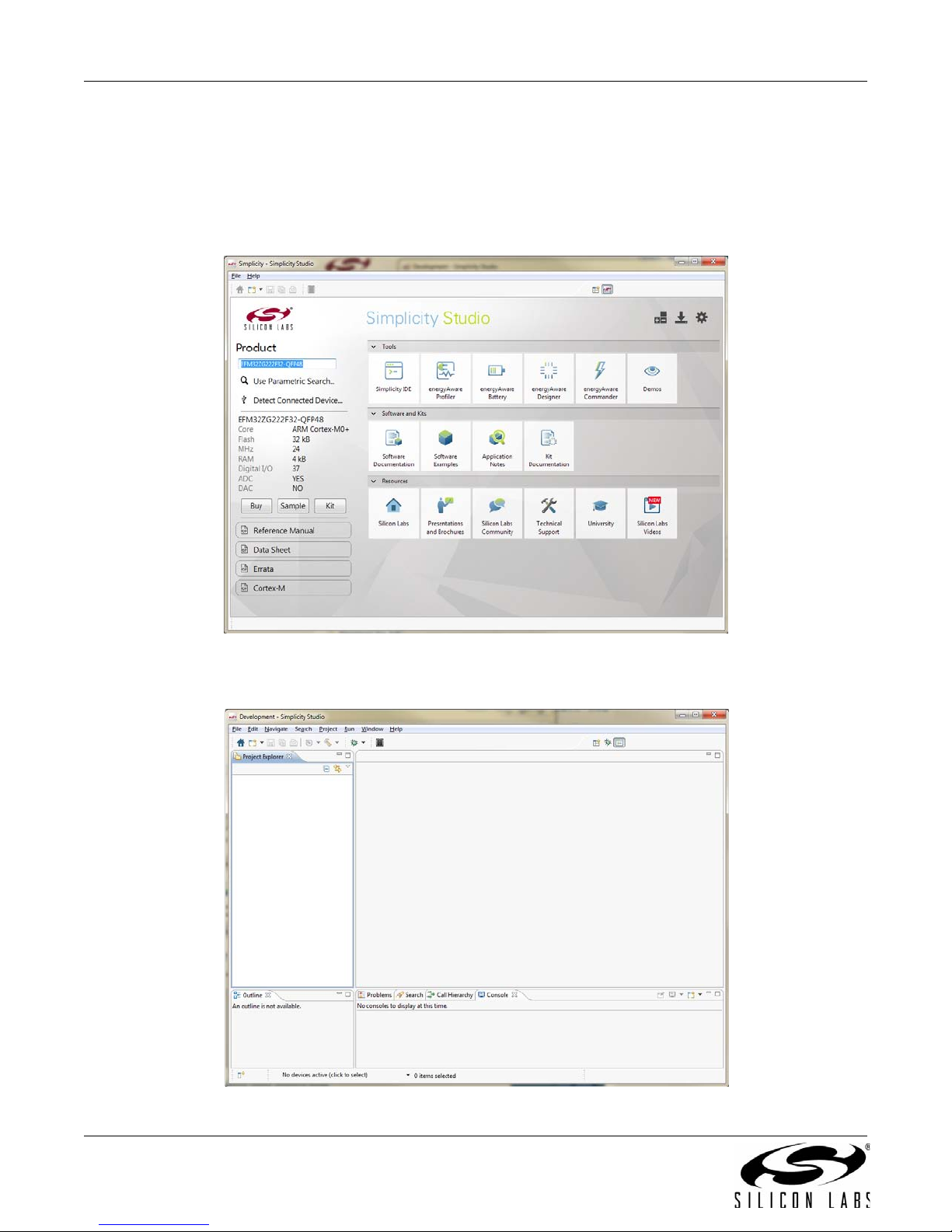
1. Connect the Wonder Gecko STK to the PC via USB.
2. Launch Simplicity Studio.
3. Open the Simplicity IDE
Figure 2. Simplicity Studio
Figure 3. Simplicity IDE
2 Rev. 0.1
Page 3
Biometric EXP EVB UG
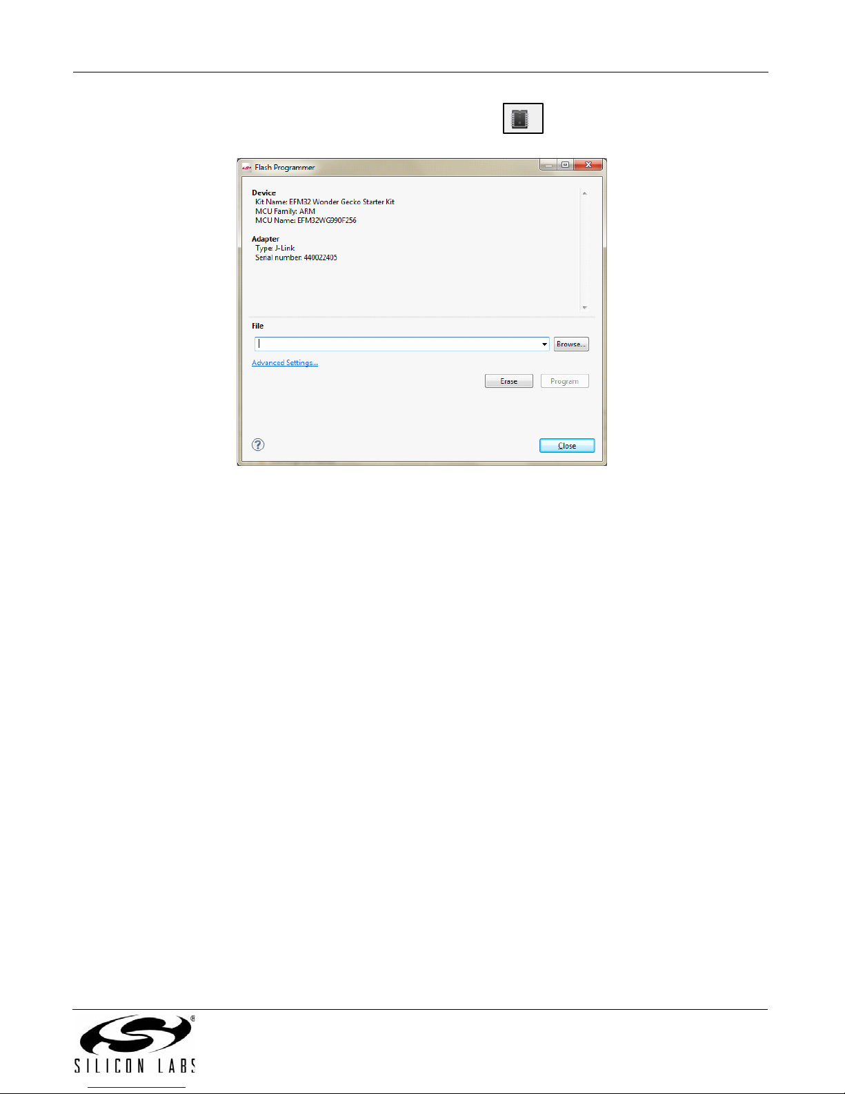
4. FromtheSimplicityIDEtoolbaropentheflashprogrammer( icon).
Figure 4. Flash Programmer Dialog
5. Ensure that the Wonder Gecko STK appears in the Device description at the top of the Flash Programmer
dialog.
6. Browse to the hex file EFM32WG_Biometric_EXP_Demo.hex then click Program.
Rev. 0.1 3
Page 4

Biometric EXP EVB UG
3. Running the Demo
A Silicon Labs EFM32 Wonder Gecko Starter Kit (EFM32WG-STK3800) and a Silicon Labs Biometric-EXP (see
Figure 1) is needed to run the Biometric EXP Demo.
The Biometric-EXP demo application uses the Wonder-Gecko STK’s LCD to display sensor output and the two
push buttons, PB0 and PB1, to cycle through the modes of the demo. The full operation including startup is
illustrated in Figures 5 and 6.
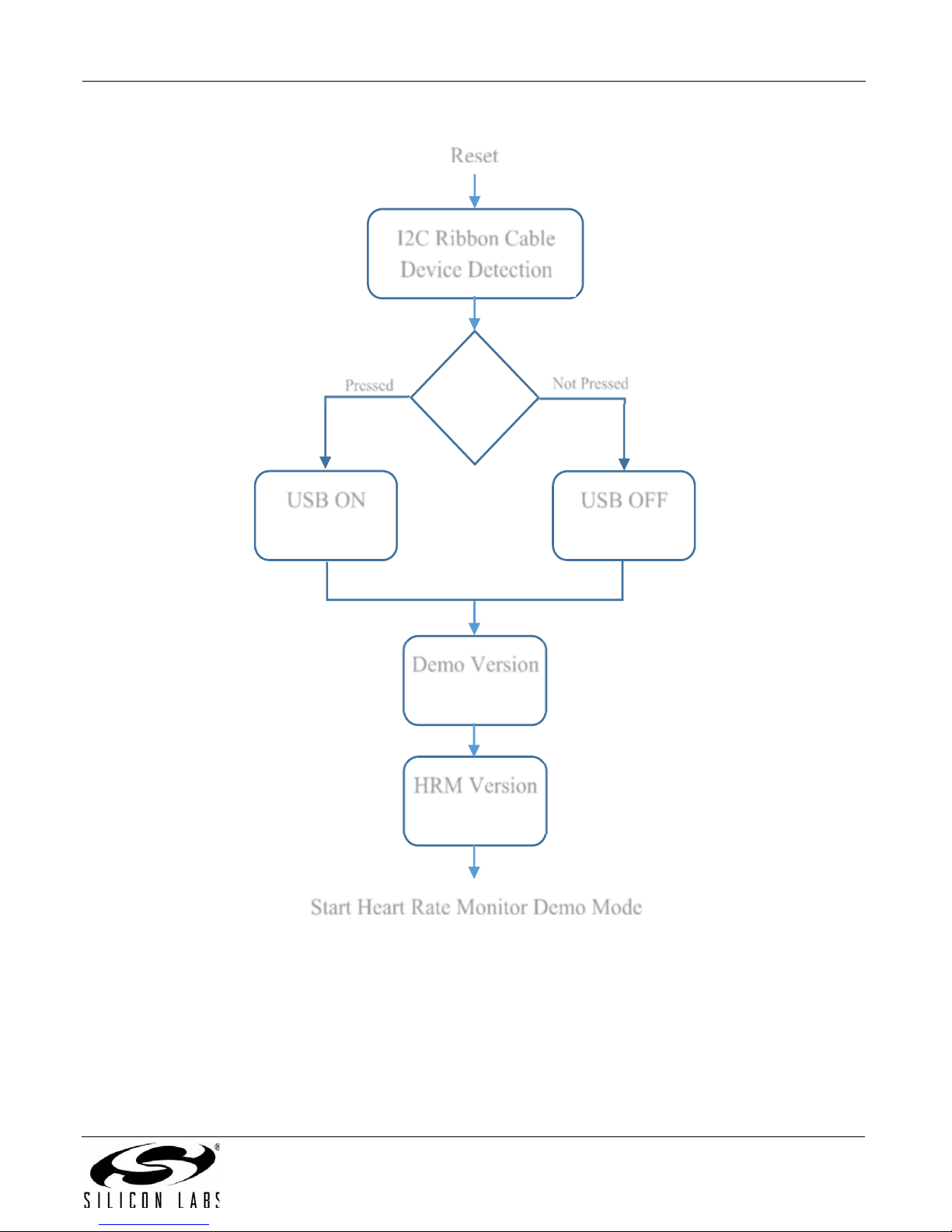
3.1. Demo Startup
Upon reset, the demo will first check whether PB0 is pressed then store the result. It will then search for a
supported device on the 6-pin ribbon cable connector. If a HRM-GGG-PS, Si1143-M01-PS or Si1147-M01-PS is
detected, the demo will automatica lly use that device for HRM measurements. In this case, the Si1146 sensor
onboard the Biometric-EXP will not be utilized. SpO2 is not available with either the HRM-GGG-PS or the Si114xM01-PS EVB's.
Following the search for a ribbon cable device, the demo will check the stored value of PB0 to enable or disable the
USB debug mode accordingly and display an USB On or USB Off message for 1 second. Refer to “4. USB Debug
Mode” for details on USB debug mode. Lastly, the demo will display version information then start the demo in
Heart Rate Monitor mode.
4 Rev. 0.1
Page 5
'HPR9HUVLRQ
86%21
,&5LEERQ&DEOH
'HYLFH'HWHFWLRQ
5
HVHW
86%2))
+509HUVLRQ
3UHVVHG
1RW3UHVVHG
6WDUW+HDUW5DWH0RQLWRU'HPR0RGH
3%3UHVVHG"
'LVSOD\HGIRUV 'LVSOD\HGIRUV
(Displayed for 1 s)
(Displayed for 1 s)
Biometric EXP EVB UG
Figure 5. Biometric-EXP Demo Startup Sequence
Rev. 0.1 5
Page 6
Biometric EXP EVB UG
HeartRate
Monitor
(^i1146)
+XPLGLW\
6HQVRU
6L
7HPSHUDWXUH
6HQVRU&
6L
7HPSHUDWXUH
6HQVRU)
6L
8OWUDYLROHW
6HQVRU
6L
6S2
0RQLWRU
6L
8VH3%DQG3%
WRF\FOHWKURXJK
PRGHVRIWKHGHPR
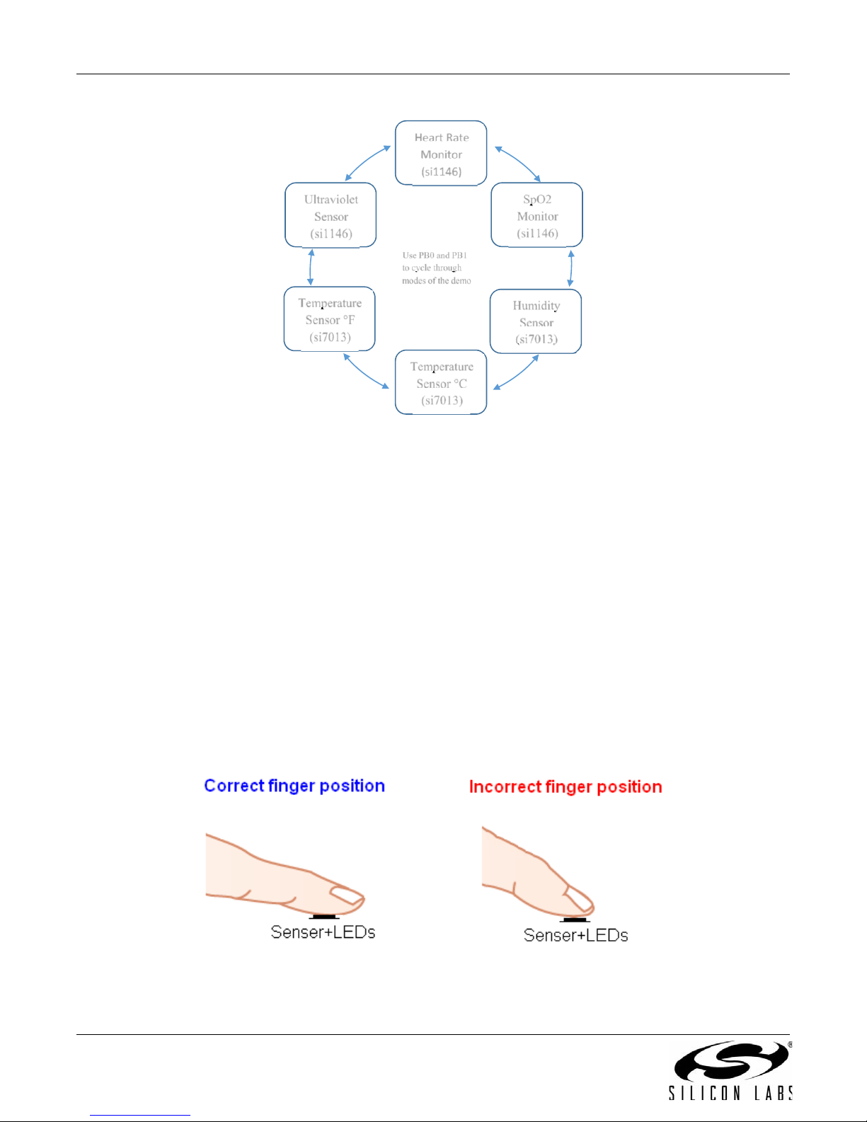
Figure 6. Biometric-EXP Demo Modes
*Note: SpO2 Monitor mode is not available when using a HRM-GGG-PS, Si1143-M01-PS or Si1147-M01-PS.
3.2. Heart Rate Monitor Mode
When heart rate monitor demo is idle, the LCD will show the word “Pulse” followed by a message instructing the
user to place his/her finger on the optical sensor. In idle mode, the sensor is not continuously sampling. Rather, it
executes one sample ever y two seconds by performing a forced measurement . That sample is then analyze d to
determine if there is skin contact with the sensor. Only when the application detects skin contact does it begin
sampling continuously and running the HRM algorithm. It will remain in run mode (continuous sampling) until skin
contact is removed for greater than two seconds. This approach significantly reduces power usage when idle.
When the application is acquiring the heart rate, it will display the word “Wait” on the LCD. It typically takes five to
seven seconds to acquire a valid heart rate. Once a valid heart rate is measured, the display will show the heart
rate. If the heart rate is not displayed within seven seconds, it is likely that the algorithm cannot get a valid pulse
rate. When this occurs, the user should remove his/her finger and try it again adjusting the position of the finger
and the finger pressure as needed.
Proper finger position in relation to the sensor and LEDs as well as proper finger pressure is essential for accurate
measurements. The finger should fully cover both LEDs and the sensor. Proper finger position is illustrated in
Figure 7.
6 Rev. 0.1
Figure 7. Proper Finger Placement
Page 7

Biometric EXP EVB UG
3.3. SpO2 Monitor Mode
When SpO2 mode is active, the LCD will show “SpO2” followed by a message instructing the user to place his/her
finger on the optical sensor. Beyond that, SpO2 monitor mode mirrors the operation of the Heart Rate Monitor
mode as described in “3.2. Heart Rate Monitor Mode” . Please note that SpO2 mode is not available when using a
HRM-GGG-PS, Si1143-M01-PS, or Si1147-M01-PS device via the 6-pin ribbon cable. Even more so than HRM,
proper finger position and pressure is important to achieve a good SpO2 measurement. Refer to Figure 7 for an
illustration of proper finger position.
3.4. Ultraviolet Sensor Mode
When the UV sensor mode is active, the LCD will show “UV” followed by the measured UV index. In this mode, the
UV reading is updated every two seconds.
3.5. Temperature Sensor Mode
In the temperature sensor modes, the LCD will show the temperature in Fahrenheit or Celcius as indicated by an
“F” or a “C” following the reading. In this mode the temperature reading is updated every two seconds.
3.6. Relative Humidity Sensor Mode
In the relative humidity sensor mode, the LCD will show “RH” followed by the relative humidity reading. In this
modem, the relative humidity reading is updated every two seconds.
Rev. 0.1 7
Page 8

Biometric EXP EVB UG
4. USB Debug Mode
The Biometric-EXP demo firmware includes a debug mode that enables Heart Rate Monitor and SpO2 raw
samples from the sensor to be streamed to a host PC via the Wonder Gecko STK’s USB interface. Only HRM and
SpO2 data is available via the USB debug interface. UV, Relative Humidity, and Temperature data is not available.
4.1. Enabling USB Debug Mode
In order to maintain power efficiency of the demo, the USB debug mode is disabled by default. The LCD will show
“USB OFF” during startup. To enable USB debug mode, the user must hold down button PB0 then press and
release the Reset button. Both buttons are on the W onder Gecko STK a s shown in Figur e 19. The user should hold
down PB0 until the LCD shows “USB ON.” At this point, USB is enabled and the demo will run normally. To later
disable USB debug mode the user can press the Reset button without holding PB0.
4.2. Connecting to USB Debug Mode on a PC
Prior to using USB debug mode, the user must first install the Biometric-EXP Windows Evaluation Software. This
will install the Windows applications and drivers necessary to use USB debug mode. The Wonder Gecko STK has
two USB type connectors: a USB Mini type connector labeled J-Link on the short side of the EVB and a USB Micro
type connector on the long side of the EVB. Refer to Figure 19 on page 20 for details on the component layout of
the Wonder Gecko STK. The USB Micro connector is used for the USB debug interface. In addition to using the
correct physical interface, the Power Source Select switch must be set to USB (center position) for proper
operation.
USB debug mode utilizes a Virtual COM Port (VCP) interface to communicate between the Biometric-EXP demo
and the PC. With the Windows software installed, USB debug mode enabled on the Wonder Gecko and a USB
cable connecting the Wonder Gecko STK and the PC, the device will appear in Windows Device Manager as a
COM port as shown in Figure 8.
8 Rev. 0.1
Page 9

Biometric EXP EVB UG
Figure 8. Biometric-EXP Virtual COM Port Device in Windows Device Manager
Rev. 0.1 9
Page 10

Biometric EXP EVB UG
4.3. Windows Applications for USB Debug Mode
The Biometric-EXP Windows Evaluation Software includes two Windows applications for evaluating and
debugging the Biometric-EXP Heart Rate Monitor and SpO2 functions. The Windows Graphical User Interface
(GUI) demo provides a waveform display of the HRM data along with the HRM and SpO2 calculated values. The
GUI demo also allows the user to record the streaming data to a file for further analysis. A screens hot of the GUI
demo is shown in Figure 9.
Figure 9. Windows Graphical User Interface Demo
The Windows Console Demo provides a running, once-per-second text output of many parameters that are used
within the HRM and SpO2 algorithms including the HRM and SpO2 results. This tool can be used for advanced
analysis of the HRM and SpO2 streaming data; however, the details of the parameters and how to use them to
analyze a HRM-SpO2 recording is beyond the scope of this document. Refer to the HRM-SpO2 API Reference
Manual available from Silicon Laboratories for further details. The C++ source code of the Console Demo is
supplied within the installation. A screen shot of the Console demo is show in Figure 10.
10 Rev. 0.1
Page 11

Biometric EXP EVB UG
Figure 10. Windows Console Demo
To connect the console to the streaming output from the Biometric-EXP, the user can type –u COMx <filename> at
the prompt. In this command, COMx is the VCP COM port as shown in Figure 8, and the optional input <filename>
specifies the file in which the streaming data is to be stored. Note that if <filename> is not provided, the console
automatically stores the data to a default file. This default file is overwritten each time the demo is run.
The console also has the ability to playback recorded files. This is done by typing –f filename at the prompt. In
this command, filename specifies the source file containing the saved recording.
It is important to note that the USB debug interface is a one-way interface. Therefore, the applications can only
take the streaming data as an input. They do not allow the user to control the Biometric-EXP software.
Rev. 0.1 11
Page 12

Biometric EXP EVB UG
5. Importing the Source Code Project into Simplicity Studio
The following steps will import the Biometric-EXP Demo source code into Simplicity Studio resulting in a project
that can be compiled, linked and debugged using the Wonder Gecko starter kit.
Simplicity Studio is available for download at www.silabs.com/simplicity-studio
Note: In the near future, this software will be integrated into Simplicity Studio making the import task seamless. When the inte-
gration is complete, the procedure below will be obsolete.
1. Store the Biometric-EXP software distribution uncompressed in a folder that is accessible from the PC.
2. Start Simplicity Studio and Open the Simplicity IDE.
.
12 Rev. 0.1
Figure 11. Simplicity Studio
Page 13

Biometric EXP EVB UG
Figure 12. Simplicity IDE
3. In the Simplicity IDE menu select FileImport.
4. Under the General heading, select Existing Projects into the Workspace then click Next.
Rev. 0.1 13
Page 14

Biometric EXP EVB UG
Figure 13. Simplicity IDE Import Dialog
5. Select Select root directory then Browse to the folder EFM32WG_Biometric_EXP_Demo in the
Biometric-EXP Demo distribution.
14 Rev. 0.1
Page 15

Biometric EXP EVB UG
Figure 14. Select the Project to Import
6. Confirm that the check box for the project is checked.
7. If you wish to make a local copy within the Simplicity IDE workspace select Copy projects into
workspace.
8. Click Finish.
9. The EFM32WG_Biometric_EXP_Demo project is configured to link to a binary library that is stored in a
folder labeled lib in the Simplicity IDE workspace folder . This folder is not generated by the import pro cess
described in the steps above; therefore, the link will be broken.
Rev. 0.1 15
Page 16

Biometric EXP EVB UG
Figure 15. Simplicity IDE with EFM32WG_Biometric_EXP_Demo Project
To correct the link:
a. In the Simplicity IDE Project Explorer, right click on the lib folder then select Properties.
b. The Resources page of the Properties dialog displays the link path. Modify this path by clicking the
Edit button then browsing to the location of the lib folder.
Note: Alternatively, you can manually copy the entire lib folder from the distribution to the location specified in step “b”.
16 Rev. 0.1
Page 17

Biometric EXP EVB UG
Figure 16. Symbolic Link to the Lib Folder
Upon completion of the steps above you should have a working project in Simplicity Studio that can be built and
debugged.
10. To build the demo, simply click on the icon in the Simplicity IDE. Note that there are two build
configurations: Release and Debug. You can select between the two by clicking the down arrow next to
the Hammer icon.
1 1. To debug the project, select the Debug build configuration then click on the icon in the Simplicity
IDE. A debug session will automatically launch and if a board is connected, the project will be loaded into
the MCU.
Rev. 0.1 17
Page 18

Biometric EXP EVB UG
EXP Connector
(JP3)
EXP Connector
(JP4)
TS3310 DC-DC
Boost Converter
Si1146 Proximity/
UV/Ambient Light
Sensor
Si7013 Humidity
& Temperature
Sensor
I2C Ribbon
Connector
(J6)
Red
IR
5V
Vmcu
I2C1
All other lines
I2C2
6. Hardware Overview
6.1. Block Diagram
6.2. Hardware Connectors
As illustrated in Figure 17 there are two separate I2C buses implemented on this board. The Si1146 is on its own
bus while the Si7013 and the I2C Ribbon Connector J6 are on the second bus. This allows for expansion boards
designed for the I
address conflict between any potential Si1145/Si1146/Si1147 devices on the expansion board.
Table 1 details the pinouts and signal function of the Biometric-EXP connectors JP3 and JP4.
Figure 17. Biometric-EXP Block Diagram
2
C Ribbon Connector to connect to the Biometric-EXP without the possibility of an I2C slave
Table 1. Expansion Connectors (JP3 and JP4)
Pin # Biometric-EXP Signal Description WonderGecko Signal
1GND GND
2 VMCU VMCU
3Red LED D3 PC0
4Not Used PD0
5 Green LED D3 PC3
6Not Used PD1
7 Si7013 and I
2
C Ribbon Connector (J6) SDA PC4
18 Rev. 0.1
Page 19

Biometric EXP EVB UG
Table 1. Expansion Connectors (JP3 and JP4) (Continued)
Pin # Biometric-EXP Signal Description WonderGecko Signal
8Not Used PD2
9 Si7013 and I
10 Not Used PD3
11 Not Used PB11
12 Enable TS3310 Boost DC-DC Converter PD4
13 Not Used PB12
14 Si1146 and I
15 Not Used PC6
16 Si1146 I
17 Si1146 I
18 Not Used 5V
2
C Ribbon Connector (J6) SCL PC5
2
C Ribbon Connector (J6) INT PD5
2
C SDA PD6
2
C SCL PD7
19 Not Used GND
20 3.3 V 3.3 V
Table 2 details the pinouts and signal descriptions of the 6-pin I2C connector J6.
Table 2. 6-Pin I2C Connector (J6)
Pin # Signal Description
1I2C SCL
25V
3I2C SDA
4GND
5INT
6VMCU
Rev. 0.1 19
Page 20

Biometric EXP EVB UG
Si1146 Proximity/UV/Ambient Light
IR and Red LEDs
EXP connector for
EFM32 STK
Silabs TS3310 DC-DC
Boost Converter
I2C Ribbon Cable
Connector
Si7013 Humidity &
Tem
p
erature
%XWWRQ3%
%XWWRQ3%
5HVHW%XWWRQ
(;3+HDGHU
86%'HEXJ,QWHUIDFH
()0:RQGHU
*HFNR 0&8
3RZHU6RXUFH
6HOHFW
&RLQ&HOO
%DWWHU\
-/LQN'HYHORSPHQW
,QWHUIDFH
/&'
6.3. Hardware Component Layout
Figure 18. Biometric-EXP Hardware Component Layout
Figure 19. Wonder Gecko STK Component Layout
20 Rev. 0.1
Page 21

6.4. Schematic
thermistor interface
Remote Thermistor
Remote Thermistor
CON3 - Red LED
CON5 - Green LED
CON7 - 6-pin connector SDA
CON9 - 6-pin connector SCL
CON14 - Interrupt from Prox sensor
CON15 - SCL ZeroGecko
CON16 - SDA
CON17 - EBID SCL for ZeroGecko- SCL for WonderGecko
CON19 - EBID SDA for ZeroGecko- GND for WonderGecko
Pull ups to hold pins high if disconnected
Pull ups to hold pins high if disconnected
J15/J16:
Upper position for Gecko 0 and newer boards
Lower position for older boards without support for EBID
Option to pass locally generated +5V
high = 4.1V low = 5.0V
NC - Normally Connected
NO - Normally Open
To configure this board to be used on ZeroGecko:
Connect J15, J19, and J21
Disconnect J16, J18, and J20
CON3
CON5
CON7
CON9
CON11
CON13
SCL
CON19
CON4
CON6
CON8
CON10
CON12
CON14
CON16
CON18
CON3
CON5
CON7
CON9
CON11
CON13
SCL
CON17
CON19 CON20
CON6
CON4
CON8
CON10
CON12
CON14
CON16
CON18
CON12
CON9
SCL
SDA_P
INT_P
CON15
CON20
CON7
CON16
CON14
CON5
CON3
CON16
CON7
SCL_P
CON14
SCL
CON9
+5V
+5V
VMCU
VMCU
VMCU
VMCU
3V3
VMCU
3V3
+5V
VMCU
+5V
+5V
VMCU
VMCU
R7
24.3K
TP5
+5V
C4
47uF
PCB3
JP3
Socket 2x10 RA
13579
111315
2468101214
16
17
19
18
20
G
R
D3
598-8410-207CF
TP8
SCL
PCB1
R10
4.99K
R3
24.3K
J1
NC
PCB7
J10 NC
TP7
SDA
J20
NO
R6
10K
PCB8
C8
0.1uF
-t°
R5
10K
J4
NC
J14
NC
J8 NC
TP6
CS/INTb
R13
10K
U2
Si7013
SDA
1
ADD/VOUT
2
VDDA
8
VINN
7
GNDD
3
VSNS
5
VDDD
9
VINP
6
SCL
10
EPAD
11
GNDA
4
J3
NC
PCB4
J9 NC
TP1
VINP
NI
R11
4.99K
J12
NC
R14
10K
J5
NO
J6
FH12
11223344556
6
R1 100K
TP3
VINN
NI
TP9
GND
J2
NC
JP4
HEADER 2x10 RA
13579
111315
2468101214
16
17
19
18
20
R16
47
J16
NC
R2 100K
WA1
4061T111
PCB5
R4
0
R8
4.99K
J7 NC
C11
47uF
C6
0.1uF
C2
0.1uF
R9
4.99K
C7
0.1uF
J15
NO
J17
NC
R12
4.99K
L1
47uH
J18
NC
U6 TS3310
S1
4
STORE
9
S0
2
VGOOD
6
OUT_ON
1
LSW
8
IN
3
OUT
10
S2
5
EPAD
11
GND
7
C5
0.1uF
J11 NC
J21
NC
U3
24AA024
A01A12A23VSS
4
VCC
8
SDA
5
SCL
6
WP
7
TP4
VMCU
PCB6
R18
2.00K
D1
IR
R17
47
C9
0.1uF
C10
47uF
PCB57
U7
Si1146
SDA1SCL2VDD
3
LED2
6
INT
4
VDD
7
GND
8
LED1
9
NC
10
NC
5
J13
NO
C3
47uF
J19
NO
R19
2.00K
D2
RED
PCB2
TPV1
Rev. 0.1 21
Biometric EXP EVB UG
Figure 20. Biometric EXP Schematic
Page 22

Biometric EXP EVB UG
The information in this document is believed to be accurate in all respects at the time of publication but is subject to change without notice.
Silicon Laboratories assumes no responsibility for errors and omissions, and disclaims responsibility for any consequences resulting from
the use of information included herein. Additionally, Silicon Laboratories assumes no responsibility for the functioning of undescribed features or parameters. Silicon Laboratories reserves the right to make changes without further notice. Silicon Laboratories makes no warranty, representation or guarantee regarding the suitability of its products for any particular purpose, nor does Silicon Laboratories assume any
liability arising out of the application or use of any product or circuit, and specifically disclaims any and all liability, including without limitation
consequential or incidental damages. Silicon Laboratories products are not designed, intended, or authorized for use in applications intended to support or sustain life, or for any other application in which the failure of the Silicon Laboratories product could create a situation where
personal injury or death may occur. Should Buyer purchase or use Silicon Laboratories products for any such unintended or unauthorized
application, Buyer shall indemnify and hold Silicon Laboratories harmless against all claims and damages.
CONTACT INFORMATION
Silicon Laboratories Inc.
400 West Cesar Chavez
Austin, TX 78701
Tel: 1+(512) 416-8500
Fax: 1+(512) 416-9669
Toll Free: 1+(877) 444-3032
Please visit the Silicon Labs Technical Support web page:
https://www.siliconlabs.com/support/pages/contacttechnicalsupport.aspx
and register to submit a technical support request.
Patent Notice
Silicon Labs invests in research and development to help our customers differentiate in the market with innovative low-power, small size, analogintensive mixed-signal solutions. Silicon Labs' extensive patent portfolio is a testament to our unique approach and world-class engineering team.
Silicon Laboratories and Silicon Labs are trademarks of Silicon Laboratories Inc.
Other products or brandnames mentioned herein are trademarks or registered trademarks of their respective holders.
22 Rev. 0.1
 Loading...