

Page 1
UG370: Wireless Xpress AMW007 Kit
User's Guide
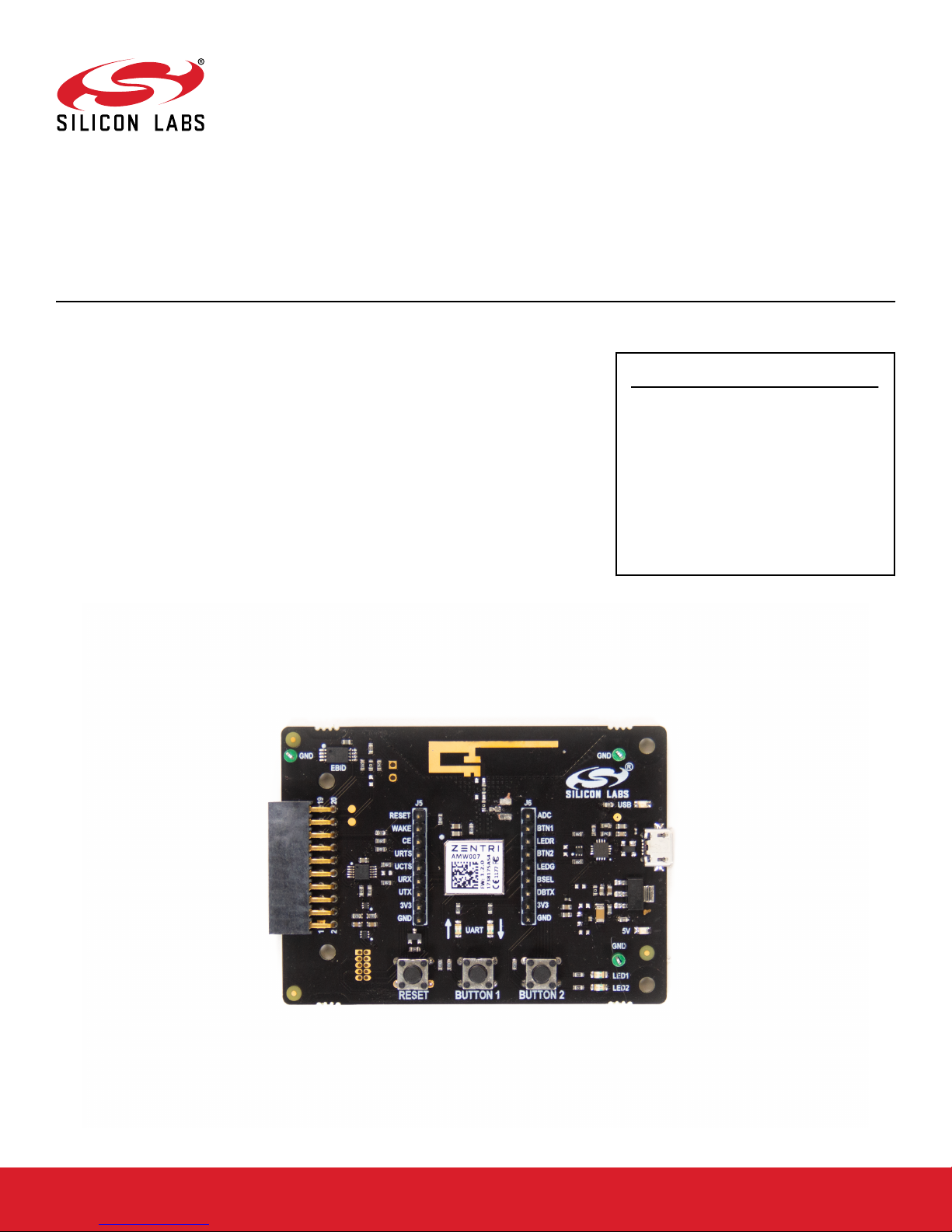
The AMW007 evaluation board is an excellent starting point to get familiar with the
AMW007 Wi-Fi module.
KEY FEATURES
The evaluation board includes everything a developer needs to exercise the AMW007’s
UART interface and demonstrate data transfer over Wi-Fi. The board can operate standalone by connecting a PC to the on-board CP2102N USB-to-UART bridge device. Alternatively, the board can be connected to a Silicon Labs EFM8 or EFM32 starter kit, where
a EFM8 or EFM32 microntroller can communicate with the AMW007 over UART.
The kit includes the following:
• AMW007 Evaluation Board
• 1 x micro USB cable
• Getting Started card
• The AMW007 can connect to an existing
Wi-Fi network or be a Wi-Fi access point.
• UART interface and flow control pins use
Gecko OS command API to connect and
communicate across Wi-Fi
• Breakout test points for easy interface with
prototype boards
• Power sources include USB and EXP
Header
silabs.com | Building a more connected world. Rev. 1.1
Page 2

UG370: Wireless Xpress AMW007 Kit User's Guide
Getting Started
1. Getting Started
Software
To set up the software for the AMW007 kit, either install Simplicity Studio, available at https://www.silabs.com/products/development-
tools/software/simplicity-studio to use Xpress Configurator or install a terminal program (e.g. Tera Term).
For most userss labeled AMW007, it will not be necessary to install a virtual comm port driver in order to interface with the AMW007 kit
using the on-board USB-to-UART bridge. Please see the section below for details.
AMW007 evaluation boards labeled AMW007-E04.2 or higher that are connected to Windows and Linux machines should be configured to this driver automatically. However, if the board is not automatically recognized by the operating system, please download and
install the latest version of the CP210x VCP driver: https://www.silabs.com/products/development-tools/software/usb-to-uart-bridge-vcp-
drivers
Hardware
To set up the hardware for the AMW007 kit:
1. Connect the micro USB cable to AMW007 board and the other end to the PC.
2. Ensure the two blue LEDs labeled USB and 5V near the USB connector are on.
3. Connect to the virtual COM port using the terminal program.
• For Windows, use a terminal program (e.g. Tera Term) set to 115200, 8N1.
• For a Mac, the terminal can be accessed using [tty.usbserial]. There may be a modifier at the end of this for your computer.
Type [tty.usbserial_modifier 115200,8n1] to set the connection to the right settings. If using a utility like CoolTerm, make sure
the settings are configured to 115200, 8N1.
Note that AMW007 kits labeled AMW007-E04.2 and higher that are connected to Windows or Linux machines do not require a driver to
be installed in order to communicate with the board. However, if using a Mac or if the driver does not automatically install, please download and install the driver from https://www.silabs.com/products/development-tools/software/usb-to-uart-bridge-vcp-drivers.
silabs.com | Building a more connected world. Rev. 1.1 | 2
Page 3
UG370: Wireless Xpress AMW007 Kit User's Guide
Getting Started
Check the Version
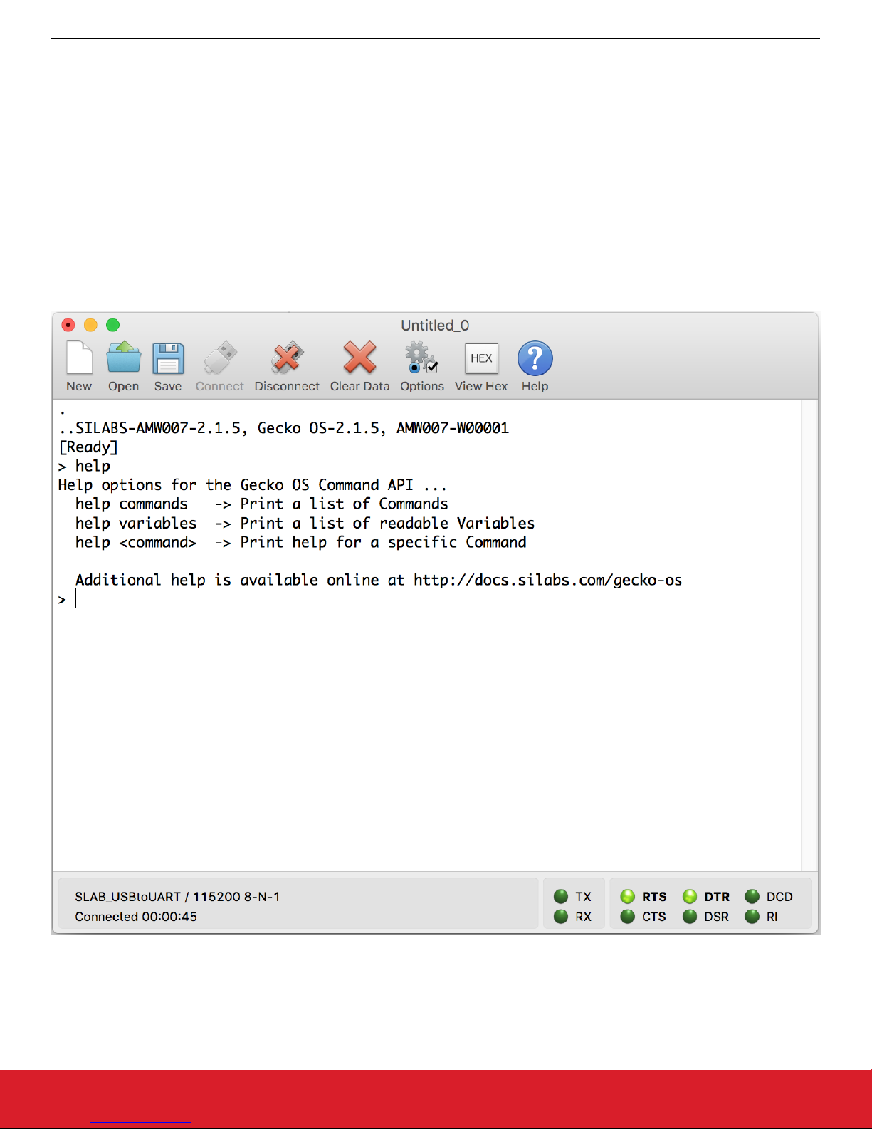
After connecting the board to the PC and opening the terminal program, press the [[RESET]] button on the board. You should see a
header with the version information for the device. Ensure this version is 2.1.5 or newer. If you find you are using an older version of
firmware, perform an over the air update on the board as described on docs.silabs.com.
help
The [help] command provides information both for commands and variables on the device.
Variables are system-level variables that determine the configuration of the AMW007 module.
Commands are actions that can be taken.
1. Type [help] to see the options for the help command.
2. Type [help commands] to see a list of commands supported by this module.
Commands used:
• https://docs.silabs.com/gecko-os/latest/cmd/commands#help
silabs.com | Building a more connected world. Rev. 1.1 | 3
Figure 1.1. help
Page 4
UG370: Wireless Xpress AMW007 Kit User's Guide
Getting Started
Claiming Your Device
The Zentri Device Management Service (ZentriDMS) tracks GeckoOS devices, their owners, their firmware configuration and many other details. The DMS handles Over-the-Air (OTA) updates, providing a secure way to update devices in the field. You need a free DMS
account before using DMS features like OTA.
To create an account go to the DMS Signup page. The DMS username (your email address) and password you register are used when
you claim your device. To claim your device, in the terminal, issue the dms claim command:
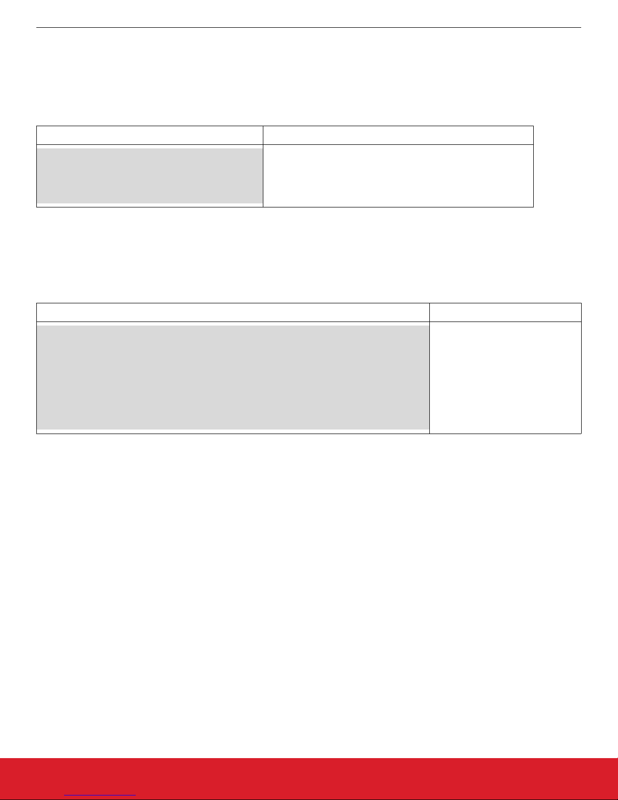
GeckoOS command Description
dms claim YOUR_DMS_USERNAME YOUR_DMS_PASSWORD
Request POST /claim
Connecting (https): ota.zentri.com:443
Starting TLS
{"result":"ok"}
claims your device. GeckoOS response shows a successful result
Once you have successfully claimed your device, you can OTA.
Performing an OTA
Use OTA to update to the latest version of your device's GeckoOS product, or to load a development GeckoOS device with a specific
GeckoOS product or version. You need to claim your device before performing an OTA. See above.
To OTA, in the GeckoOS terminal, issue the ota command:
Gecko OS command Description
ota
Disassociated]
UUID: 06413041000000002E0049001951343438333231
Connecting to network
Security type from probe: WPA2-AES
Request POST /ota
Connecting (https): ota.zentri.com:443
Starting TLS
Bundle size: 729088, Free space: 823296, Core size: 425984
Bundle version: ZENTRI-AMW106-3.4.1.0, 2017-09-01T03:14:19Z, ZentriOS-W-3.4.1.0
Updates your device via the DMS
server
GeckoOS displays progress messages
For full details of the DMS claim and OTA update process, see docs.silabs.com.
silabs.com | Building a more connected world. Rev. 1.1 | 4
Page 5
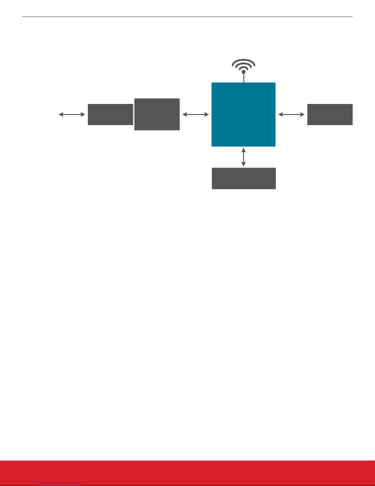
2. Kit Block Diagram
An overview of the AMW007 evaluation board is shown in the figure below.
UG370: Wireless Xpress AMW007 Kit User's Guide
Kit Block Diagram
Wi-Fi
From PC
USB
USB Micro
Connector
Figure 2.1. AMW007 Evaluation Board Block Diagram
CP2102N
UART-to-
USB bridge
UART
AMW007
Module
2 x Buttons
2 x LEDs
Expansion
Header
silabs.com | Building a more connected world. Rev. 1.1 | 5
Page 6
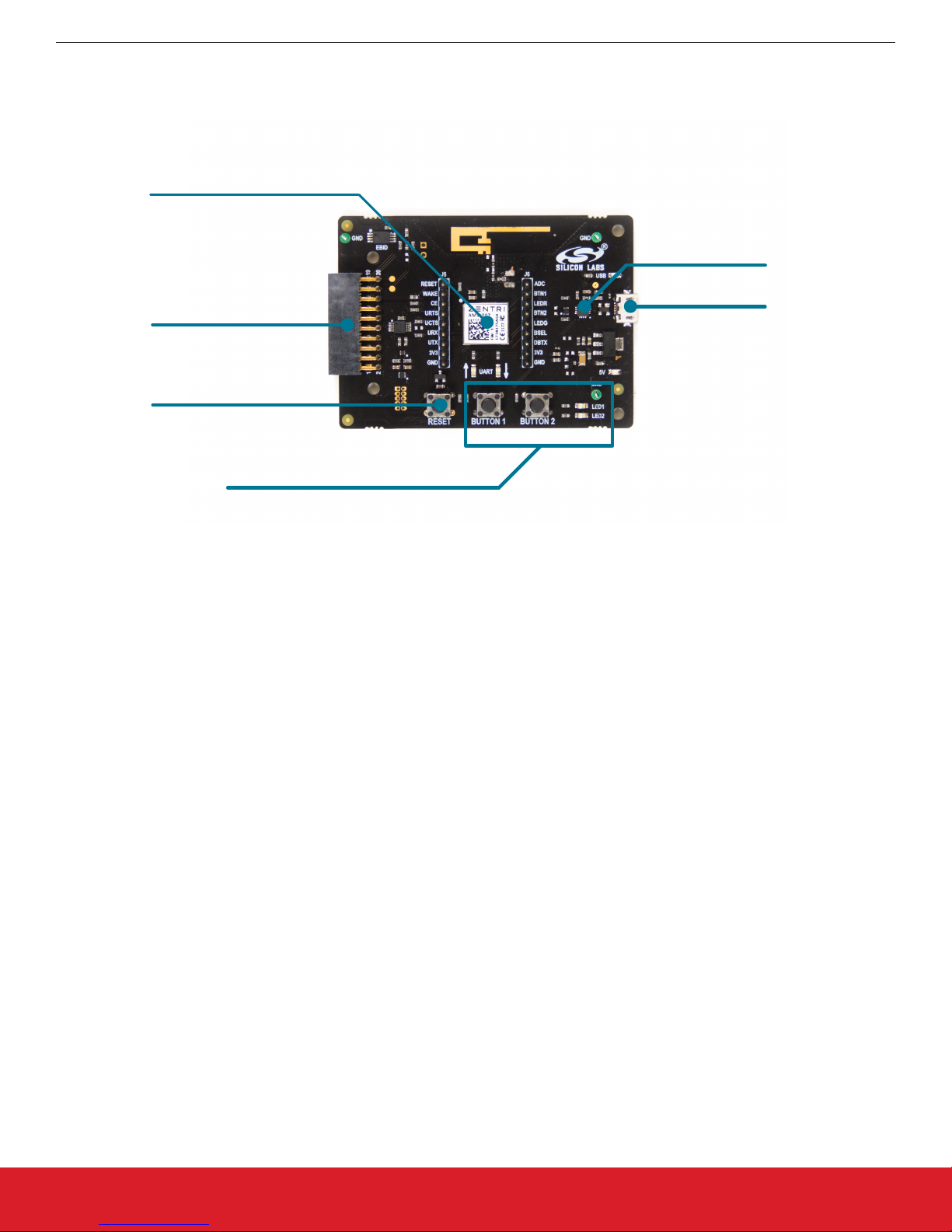
3. Kit Hardware Layout
The layout of the AMW007 evaluation board is shown below.
AMW007 Module
Expansion Header
Reset Button
UG370: Wireless Xpress AMW007 Kit User's Guide
Kit Hardware Layout
CP2102N
USB-to-serial
USB
Buttons and LEDs
Figure 3.1. AMW007 Evaluation Board Hardware Layout
silabs.com | Building a more connected world. Rev. 1.1 | 6
Page 7

4. Power and Operation
4.1 Power Selection
The AMW007 evaluation board is designed to be powered by two different sources:
• External regulator via 5V from USB connector
• External regulator via 5V from expansion header
The figure shows how the different power sources are connected to the AMW007.
UG370: Wireless Xpress AMW007 Kit User's Guide
Power and Operation
USB Micro
5V
Connector
Automatically
Expansion
Switches
Regulator
5V
3.3V
Header
AMW
Module
Figure 4.1. AMW007 Power Supply
When the USB is connected, the AMW007 is powered from the external regulator, and the external regulator is powered by the USB
cable.
The external regulator also be powered externally through the 5V and GND pins of the expansion header when the board is attached to
a power supply or an EFM MCU Starter Kit.
When power is provided through the USB or an external power supply, the AMW007 module can act as a stand alone device. When it
is connected to an EFM MCU Starter Kit through the expansion header, the AMW007 acts as a peripheral to the MCU.
4.2 Stand-alone
In stand-alone mode, the AMW007 on the evaluation board can be communicated with using the USB-to-UART bridge device. Simply
connect to the CP2102N’s virtual COM port in a terminal program and send commands to the AMW007.
Note: By default, the AMW007 communicates at 115200 baud, though this is a configurable setting.
silabs.com | Building a more connected world. Rev. 1.1 | 7
Page 8

UG370: Wireless Xpress AMW007 Kit User's Guide
Power and Operation
4.2.1 AMW007 as an Access Point
To set up the AMW007 as an access point using a terminal program:
1. Connect to the AMW007 expansion board's COM port using a terminal program.
2. Set/Get commands access variables that configure operation and features in the device. Type [set setup.web.ssid] to ["GeckoOS
#"], where [#] is a unique SSID that will be easy to see on a list of other SSIDs as shown in Figure 1.3. Ensure this SSID does not
match any nearby SSIDs. Note that you will need quotes around the network name if it contains spaces.
Note: The [Get/Set] commands access variables that configure operation and features in the device. [Get] reads a variable from
RAM and [Set] writes a new value to that variable in RAM.
3. To read the password on the network, call [get setup.web.passkey]. The default password is "password". Set the password for
the network by calling [set setup.web.passkey].
4. Type [save] to save the new SSID values.
Note: The [save] command saves the [ssid] variable to flash.
5. Type [setup web] to enable the module as a Wi-Fi access point.
Note: By default, Gecko OS evaluation boards are configured to enter Setup Web mode when you hold down Button 2, press Reset, and continue to hold down Button 2 for at least three seconds.
Figure 4.2. setup web / set setup.web.ssid / save / get setup.web.passkey
silabs.com | Building a more connected world. Rev. 1.1 | 8
Page 9

UG370: Wireless Xpress AMW007 Kit User's Guide
Power and Operation
6. Configure GPIO 5 to be an input by executing the command 'gpio_dir 5 in'. Note that this is done to illustrate additional capability in
step 9 of this QSG. This command is not typically required to configure your device.
7. Using your computer or phone, connect to the Gecko OS access point [Gecko OS #] using the password.
Figure 4.3. Connecting to the Gecko OS Access Point
8. Using a web browser, go to setup.com.
9. Click the [GPIOs] area on the left side of the browser.
silabs.com | Building a more connected world. Rev. 1.1 | 9
Figure 4.4. Navigating to the Module's index.html
Page 10

UG370: Wireless Xpress AMW007 Kit User's Guide
Power and Operation
10. Press and hold the [BUTTON 2] switch on the AMW007 board to change the GPIO toggle on the webpage. Note that the GPIO
state is able to be read because that GPIO was configured as an input earlier in this tutorial.
Figure 4.5. Toggling the GPIO Using the Buttons
Please see https://docs.silabs.com/ for a complete description of all commands and variables used in this tutorial.
4.2.2 Connecting to an Existing Network
Connecting to an Existing Network using a Terminal Program
To connect to an existing Wi-Fi network using a terminal program:
1. Connect to the AMW007 expansion board using a terminal program.
2. If the AMW007 was previously configured as an access point, type [reboot] to disable the AMW007 as an access point.
3. Use the [scan] command to find all the networks in range.
Please see https://docs.silabs.com/ for a complete description of all commands and variables used in this tutorial.
silabs.com | Building a more connected world. Rev. 1.1 | 10
Figure 4.6. scan
Page 11

UG370: Wireless Xpress AMW007 Kit User's Guide
Power and Operation
Connecting to a Network
The [wlan.ssid] and [wlan.passkey] variables set the Wi-Fi network name and password, respectively.
1. Type [set wlan.ssid "Wi-Fi network name"]. The ["Wi-Fi network name"] value is the name of the network you'd like to connect
to.
Note: Use quotes around the network name if it contains spaces.
2. Type [set wlan.passkey password]. The [password] value is the password for the network defined by the ssid.
3. Type [save] to save the new values.
4. Type [network_up] to turn on the network.
You should now be connected to the network.
Figure 4.7. set wlan.ssid / set wlan.passkey / save / network_up
Note: To automatically join the network defined by [ssid] and [passkey] each time the module is powered on or rebooted, type [set
wlan.auto_join.enabled 1].
Commands used:
• https://docs.silabs.com/gecko-os/latest/cmd/commands#set
• https://docs.silabs.com/gecko-os/latest/cmd/commands#save
• https://docs.silabs.com/gecko-os/latest/cmd/commands#network-up
silabs.com | Building a more connected world. Rev. 1.1 | 11
Page 12

UG370: Wireless Xpress AMW007 Kit User's Guide
Looking for Files
GeckoOS includes full operating system commands like [ls -l]. To test this out:
1. Type [ls] to get a basic file list.
2. Type [ls -l] to view the type, flags, and other information for files in the operating system filesystem.
Power and Operation
Figure 4.8. ls / ls -l
Please see https://docs.silabs.com/ for a complete description of all commands and variables used in this tutorial.
silabs.com | Building a more connected world. Rev. 1.1 | 12
Page 13

UG370: Wireless Xpress AMW007 Kit User's Guide
Power and Operation
Reading from a File
Data sources like files and network sockets are called streams in GeckoOS. To read from one of these files:
1. Type [ls] to get a list of the files, if you don't already have it.
2. Use [file_open] to open the file. Type [file_open webapp/index.html] to open this file.
3. Type [stream_list] to view all of the open streams. Since we only have one stream open at the moment, it should have the handle
of [0].
4. Type [stream_read 0 100] to read 100 bytes from stream 0, or unauthorized.html.
Figure 4.9. ls / file_open / stream_list / stream_read
Commands used:
• https://docs.silabs.com/gecko-os/latest/cmd/commands#ls
• https://docs.silabs.com/gecko-os/latest/cmd/commands#file-open
• https://docs.silabs.com/gecko-os/latest/cmd/commands#stream-list
• https://docs.silabs.com/gecko-os/latest/cmd/commands#stream-read
Reading from a Website
To read data from a website:
1. Type [http_get www.google.com] to open a stream with the Google homepage. This should now be stream [1].
2. Type [stream_read 1 1000] to read the first 1000 bytes from the site (stream 1).
Please see https://docs.silabs.com/ for a complete description of all commands and variables used in this tutorial.
silabs.com | Building a more connected world. Rev. 1.1 | 13
Figure 4.10. http_get / stream_read
Page 14
UG370: Wireless Xpress AMW007 Kit User's Guide
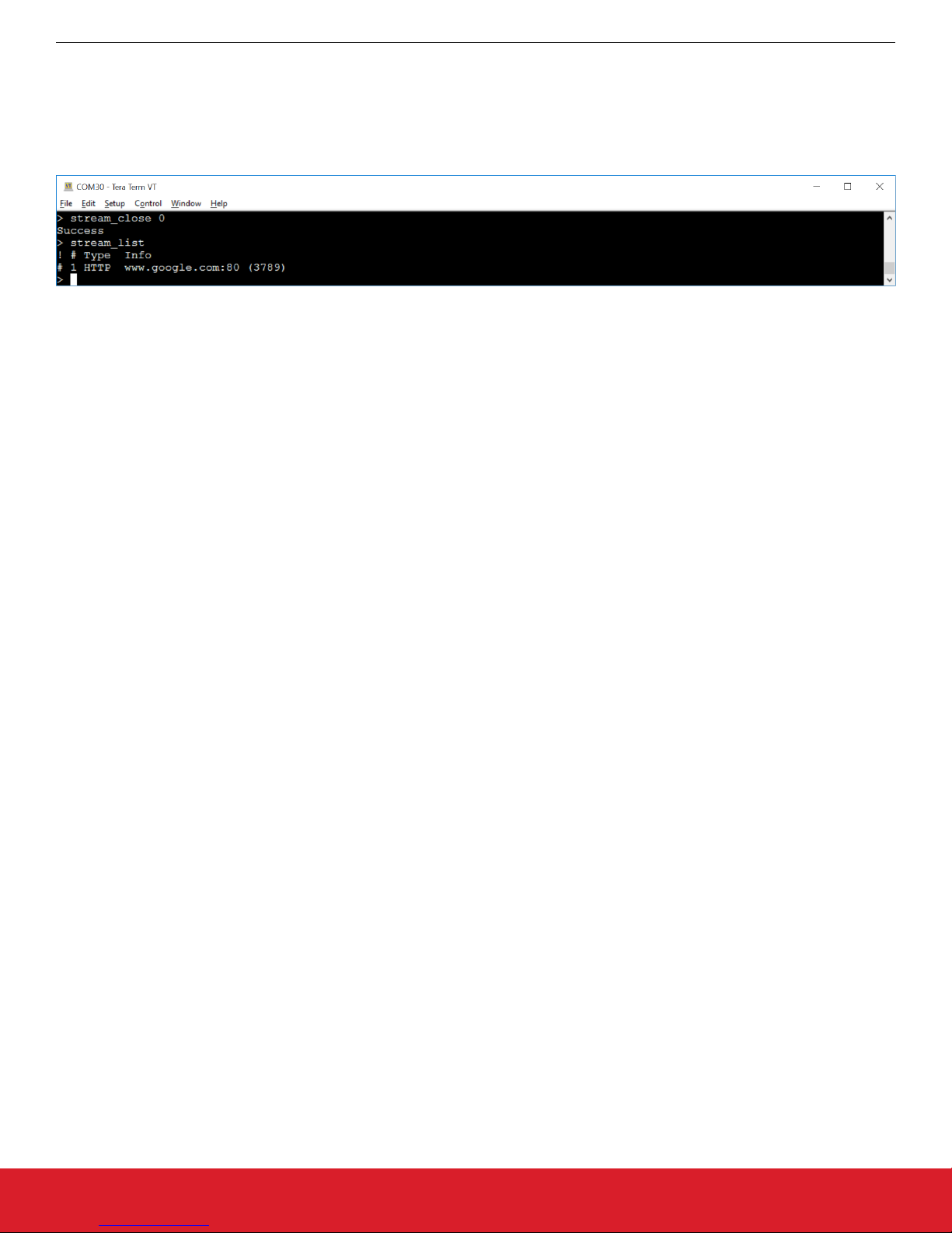
Closing a Stream
To close a stream:
1. Type [stream_close 0] to close the open stream to the unauthorized.html file.
2. Type [stream_list] to view the open streams. The open stream to the website should be the only item in the list.
Figure 4.11. stream_close / stream_list
Please see https://docs.silabs.com/ for a complete description of all commands and variables used in this tutorial.
Power and Operation
silabs.com | Building a more connected world. Rev. 1.1 | 14
Page 15

UG370: Wireless Xpress AMW007 Kit User's Guide
Peripherals
5. Peripherals
The starter kit has a set of peripherals that showcase some of the features of the AMW007 module.
Be aware that some I/O routed to peripherals are also routed to the breakout pads. This must be taken into consideration when using
the breakout pads for your application.
5.1 Push Buttons and LEDs
The board includes 2 active-high LEDs and 2 mechanical buttons to exercise I/O capabilities of the AMW007. The connections are
shown in the following table.
Table 5.1. LEDs and Buttons Connected to AMW007
AMW007 Pin LED/Button
GPIO0 BUTTON1
GPIO1 LED1 (red)
GPIO4 LED2 (green)
GPIO5 BUTTON2
silabs.com | Building a more connected world. Rev. 1.1 | 15
Page 16

UG370: Wireless Xpress AMW007 Kit User's Guide
Connectors
6. Connectors
6.1 Test Points
The test points located to the left and right of the module. Test points are available for the AMW007's power/ground pins, UART pins,
all GPIOs, reset pin, wake pin, chip enable pin, boot select pin, and debug TX pin.
Test Points
Figure 6.1. Test Points
6.2 Expansion Header
On the left hand side of the board is a female expansion header to connect to a Silicon Labs EFM8 Starter Kit (STK). The connecter
contains a number of output and communication pins that can be used to communicate with the MCU on the STK. Additionally, the 3V3
and 5V power rails are also available. The figure below shows the pin assignment of the expansion header.
NC
NC
NC
NC
19
17
15
13
11
9
7
5
3
1
EBID_SDA
EBID_SCL
See Schematic
GPIO_5
GPIO_0
GND
Top-side view, with connector on left side of the board
AMW007 pin
Power
Ground
Reserved (Board Identification)
* Only when CP2102N UART-to-USB bridge is unpowered
20
18
16
14
12
10
8
6
4
2
3V3
5V
/RESET
UART_TX*
UART_RX*
NC
NC
NC
NC
NC
silabs.com | Building a more connected world. Rev. 1.1 | 16
Figure 6.2. Expansion Header
Page 17

UG370: Wireless Xpress AMW007 Kit User's Guide
Simplicity Studio
7. Simplicity Studio
Simplicity Studio contains tools to configure and evaluate the AMW007.
7.1 Xpress Configurator
Xpress Configurator is a GUI tool used to configure parameters of the AMW007, save those values, and export settings in a number of
useful ways.
Note: All configuration of the AMW007 executes across the serial interface, and any step taken by Xpress Configurator can be reproduced by an embedded host connected to the AMW007's UART interface.
All communication between the AMW007 expansion board and the Xpress Configurator can be seen in the terminal window embedded
in the Xpress Configurator tool.
Figure 7.1. Simplicity Studio Xpress Configurator
silabs.com | Building a more connected world. Rev. 1.1 | 17
Page 18

UG370: Wireless Xpress AMW007 Kit User's Guide
Schematics, Assembly Drawings, and BOM
8. Schematics, Assembly Drawings, and BOM
8.1 Board Files
The schematics, assembly drawings and bill of materials (BOM) for the AMW007 evaluation board are available through Simplicity Studio when the kit documentation package has been installed. To access these documents, click the [Kit Documentation] tile after selecting the device in the left pane.
silabs.com | Building a more connected world. Rev. 1.1 | 18
Page 19

Simplicity Studio
One-click access to MCU and
wireless tools, documentation,
software, source code libraries &
more. Available for Windows,
Mac and Linux!
IoT Portfolio
www.silabs.com/IoT
Disclaimer
Silicon Labs intends to provide customers with the latest, accurate, and in-depth documentation of all peripherals and modules available for system and software implementers using or
intending to use the Silicon Labs products. Characterization data, available modules and peripherals, memory sizes and memory addresses refer to each specific device, and "Typical"
parameters provided can and do vary in different applications. Application examples described herein are for illustrative purposes only. Silicon Labs reserves the right to make changes
without further notice and limitation to product information, specifications, and descriptions herein, and does not give warranties as to the accuracy or completeness of the included
information. Silicon Labs shall have no liability for the consequences of use of the information supplied herein. This document does not imply or express copyright licenses granted
hereunder to design or fabricate any integrated circuits. The products are not designed or authorized to be used within any Life Support System without the specific written consent of
Silicon Labs. A "Life Support System" is any product or system intended to support or sustain life and/or health, which, if it fails, can be reasonably expected to result in significant personal
injury or death. Silicon Labs products are not designed or authorized for military applications. Silicon Labs products shall under no circumstances be used in weapons of mass
destruction including (but not limited to) nuclear, biological or chemical weapons, or missiles capable of delivering such weapons.
Trademark Information
Silicon Laboratories Inc.® , Silicon Laboratories®, Silicon Labs®, SiLabs® and the Silicon Labs logo®, Bluegiga®, Bluegiga Logo®, Clockbuilder®, CMEMS®, DSPLL®, EFM®, EFM32®,
EFR, Ember®, Energy Micro, Energy Micro logo and combinations thereof, "the world’s most energy friendly microcontrollers", Ember®, EZLink®, EZRadio®, EZRadioPRO®,
Gecko®, ISOmodem®, Micrium, Precision32®, ProSLIC®, Simplicity Studio®, SiPHY®, Telegesis, the Telegesis Logo®, USBXpress®, Zentri, Z-Wave, and others are trademarks or
registered trademarks of Silicon Labs. ARM, CORTEX, Cortex-M3 and THUMB are trademarks or registered trademarks of ARM Holdings. Keil is a registered trademark of ARM
Limited. All other products or brand names mentioned herein are trademarks of their respective holders.
Silicon Laboratories Inc.
400 West Cesar Chavez
Austin, TX 78701
USA
SW/HW
www.silabs.com/simplicity
Quality
www.silabs.com/quality
Support and Community
community.silabs.com
http://www.silabs.com
 Loading...