

Page 1

silabs.com | Building a more connected world. 1 | Page
RS9116W Wi-Fi AT Command Programming
Reference Manual
Version 2.0
10/21/2020
Page 2

RS9116W Wi-Fi AT Command Programming Reference Manual
Version 2.0
silabs.com | Building a more connected world. 2 | Page
Table of Contents
1 Architecture Overview ........................................................................................................................................... 6
1.1 Overview ......................................................................................................................................................... 6
1.2 WLAN Architecture ......................................................................................................................................... 8
2 Bootloader ............................................................................................................................................................ 10
3 Host Interfaces ..................................................................................................................................................... 27
3.1 UART Interface ............................................................................................................................................. 27
4 AT Command Mode .............................................................................................................................................. 29
5 WLAN Commands ................................................................................................................................................ 30
5.1 Set Operating Mode ...................................................................................................................................... 30
5.2 Band ............................................................................................................................................................. 46
5.3 WLAN Config ................................................................................................................................................ 47
5.4 Set MAC Address ......................................................................................................................................... 48
5.5 Init ................................................................................................................................................................. 49
5.6 User Configurable Gain Table ...................................................................................................................... 50
5.7 PER Mode .................................................................................................................................................... 54
5.8 Configure AP Mode ...................................................................................................................................... 60
5.9 WPS PIN Method .......................................................................................................................................... 62
5.10 Scan ............................................................................................................................................................. 63
5.11 Join ................................ ................................ ................................ ............................................................... 68
5.12 Request Timeout .......................................................................................................................................... 72
5.13 Re-Join ......................................................................................................................................................... 72
5.14 WMM PS....................................................................................................................................................... 73
5.15 Set Sleep Timer ............................................................................................................................................ 74
5.16 Power Mode.................................................................................................................................................. 75
5.16.1 Power Save Operation .................................................................................................................................. 76
5.16.2 Power Save Mode 1 ..................................................................................................................................... 77
5.16.3 Power Save Mode 2 ..................................................................................................................................... 78
5.16.4 Power Save Mode 3 ..................................................................................................................................... 79
5.16.5 Power Save Mode 8 ..................................................................................................................................... 80
5.16.6 Power Save Mode 9 ..................................................................................................................................... 81
5.17 PSK/PMK ...................................................................................................................................................... 82
5.18 Set WEP Keys .............................................................................................................................................. 84
5.19 Set WEP Authentication Mode...................................................................................................................... 85
5.20 Set EAP Configuration .................................................................................................................................. 85
5.21 Set Certificate ............................................................................................................................................... 86
5.22 Set Certificate with Indices............................................................................................................................ 88
5.23 Disassociate ................................................................................................................................................. 91
5.24 Set IP Parameters ........................................................................................................................................ 92
5.25 IP Change Notification .................................................................................................................................. 93
5.26 Set IPv6 Parameters ..................................................................................................................................... 94
5.27 SNMP ........................................................................................................................................................... 95
5.28 SNMP Set ..................................................................................................................................................... 96
5.29 SNMP Get Response ................................................................................................................................... 97
5.30 SNMP Get Next Response ......................................................................................................................... 101
5.31 SNMP Trap ................................................................................................................................................. 102
5.32 Open Socket ............................................................................................................................................... 105
5.33 TCP Socket Connection Established ................................ ................................ .......................................... 112
5.34 Query a Listening Socket's Active Connection Status ................................................................................ 112
5.35 Close Socket............................................................................................................................................... 113
5.36 Send Data ................................................................................................................................................... 114
5.36.1 Send Data in AT mode.................................................................................................................................114
5.37 Read Data................................................................................................................................................... 118
5.37.1 Read Data in AT mode ................................................................................................................................118
5.37.2 Receive Data on Socket ..............................................................................................................................120
5.37.3 Receive Data on Socket in AT mode ............................................................................................................120
5.38 Wireless Firmware Upgrade ....................................................................................................................... 121
5.39 Background Scan (BG scan) ...................................................................................................................... 122
5.40 Roam Parameters ....................................................................................................................................... 124
5.41 HT Caps...................................................................................................................................................... 125
5.42 DNS Server................................................................................................................................................. 126
Page 3

RS9116W Wi-Fi AT Command Programming Reference Manual
Version 2.0
silabs.com | Building a more connected world. 3 | Page
5.43 DNS Resolution .......................................................................................................................................... 127
5.44 DNS UPDATE ............................................................................................................................................. 128
5.45 HTTP Get.................................................................................................................................................... 129
5.46 HTTP Post .................................................................................................................................................. 132
5.47 HTTP Post Data .......................................................................................................................................... 135
5.48 HTTP Put .................................................................................................................................................... 136
5.49 DFS Client (802.11h) .................................................................................................................................. 138
5.50 Query Firmware Version ............................................................................................................................. 139
5.51 Query RSSI Value ...................................................................................................................................... 139
5.52 Query MAC Address ................................................................................................................................... 140
5.53 Query Network Parameters ........................................................................................................................ 141
5.54 Soft Reset ................................................................................................................................................... 143
5.55 Set/Reset Multicast Filter ............................................................................................................................ 144
5.56 Join or Leave Multicast Group .................................................................................................................... 144
5.57 Ping from Module ........................................................................................................................................ 146
5.58 Loading the Webpage ................................................................................................................................. 147
5.58.1 Loading the static webpage .........................................................................................................................147
5.58.2 Loading the dynamic webpage (Create JSON) .............................................................................................148
5.59 Clearing the Webpage ................................................................................................................................ 149
5.59.1 Erasing the webpage ...................................................................................................................................149
5.59.2 Erasing the JSON Data................................................................................................................................149
5.59.3 Clear all the Webpages................................................................................................................................150
5.60 Loading of Store Configuration Page .......................................................................................................... 151
5.61 Web Page Bypass ...................................................................................................................................... 151
5.62 Set Region .................................................................................................................................................. 152
5.63 Set Region of Access Point ........................................................................................................................ 154
5.64 PER Statistics of the Module ...................................................................................................................... 156
5.65 Remote Socket Closure .............................................................................................................................. 157
5.66 Bytes Transmitted Count on Socket ........................................................................................................... 158
5.67 Debug Prints on UART ............................................................................................................................... 158
5.68 Asynchronous Message for Connection State Notification ......................................................................... 159
5.69 TSF Synchronization Packet....................................................................................................................... 161
5.70 Station Connect/Disconnect Indication In AP Mode .................................................................................... 161
5.71 Transparent Mode Command ..................................................................................................................... 162
5.72 UART Hardware Flow control ..................................................................................................................... 163
5.73 Socket Configuration Parameters ............................................................................................................... 164
5.74 RF Current Mode Configuration .................................................................................................................. 165
5.75 Trigger Auto Configuration .......................................................................................................................... 166
5.76 HTTP Abort ................................................................................................................................................. 167
5.77 HTTP Server Credentials from Host ........................................................................................................... 167
5.78 FTP Client ................................................................................................................................................... 168
5.79 SNTP Client ................................................................................................................................................ 171
5.80 MDNS and DNS-SD ................................................................................................................................... 173
5.81 SMTP Client................................................................................................................................................ 175
5.82 POP3 Client ................................................................................................................................................ 177
5.83 IAP Init ........................................................................................................................................................ 179
5.84 Load MFI IE ................................................................................................................................................ 180
5.85 Over the Air Firmware Upgradation ............................................................................................................ 180
5.86 Read MFI Authentication Certificate ........................................................................................................... 181
5.87 Generate MFI Authentication Signature ...................................................................................................... 182
5.88 Storing Configuration Parameters ............................................................................................................... 182
5.88.1 Storing Configuration Parameters in Client mode .........................................................................................182
5.88.2 Store Configuration in Flash Memory ...........................................................................................................182
5.88.3 Enable auto-join to AP or Auto-create AP .....................................................................................................183
5.88.4 Get Information about Stored Configuration .................................................................................................183
5.88.5 Store configuration from User ......................................................................................................................184
5.89 Store Configuration Structure Parameters .................................................................................................. 186
5.90 WLAN Statistics .......................................................................................................................................... 198
5.91 Set RTC Time ............................................................................................................................................. 199
5.92 Get RTC Time ............................................................................................................................................. 200
5.93 Feature Frame ............................................................................................................................................ 201
5.94 Get RAM Dump .......................................................................................................................................... 202
5.95 Configure TX RX Buffer Ratio ..................................................................................................................... 203
5.96 Antenna Selection ....................................................................................................................................... 204
5.97 Band ........................................................................................................................................................... 205
5.98 MQTT Client ............................................................................................................................................... 205
Page 4

RS9116W Wi-Fi AT Command Programming Reference Manual
Version 2.0
silabs.com | Building a more connected world. 4 | Page
6 WLAN Error Codes ............................................................................................................................................. 213
7 Wireless Features and Mechanisms ................................................................................................................. 221
7.1 Connect Application .................................................................................................................................... 221
7.1.1 Description ..................................................................................................................................................221
7.1.2 Application Steps .........................................................................................................................................221
7.2 Firmware Upgrade Mechanisms ................................................................................................................. 224
7.3 Power Save Modes ..................................................................................................................................... 227
7.3.1 Power Save .................................................................................................................................................227
7.3.2 Power Save Operations ................................................................................................ ...............................227
7.4 Wake on Wireless ................................ ....................................................................................................... 234
7.4.1 Active High Interrupt Mode...........................................................................................................................234
7.4.2 Active Low Interrupt Mode ...........................................................................................................................235
8 WLAN AT Command Changes/Enhancements ................................................................................................ 238
9 Revision History ................................................................................................................................................. 239
10 Appendix A: Wi-Fi Operation Modes ................................................................................................................ 243
11 Appendix B: Wireless Configuration ................................................................................................................ 247
12 Appendix C: Sample AT Command Sequences .............................................................................................. 256
Page 5

RS9116W Wi-Fi AT Command Programming Reference Manual
Version 2.0
silabs.com | Building a more connected world. 5 | Page
About this Document
This document is about the RS9116 WiSeConnect architecture, boot-loader features, different command modes, and
supported host interfaces.
It lists and describes AT commands to operate the RS9116W-WiSeConnect Module Family for Wi-Fi mode. Wi-Fi AT
commands are provided along with the command parameters and their valid values with expected responses from the
modules.
This document explains implementing application software on the Host to control and operate the RS9116W module.
Page 6
RS9116W Wi-Fi AT Command Programming Reference Manual
Version 2.0
silabs.com | Building a more connected world. 6 | Page
1 Architecture Overview
1.1 Overview
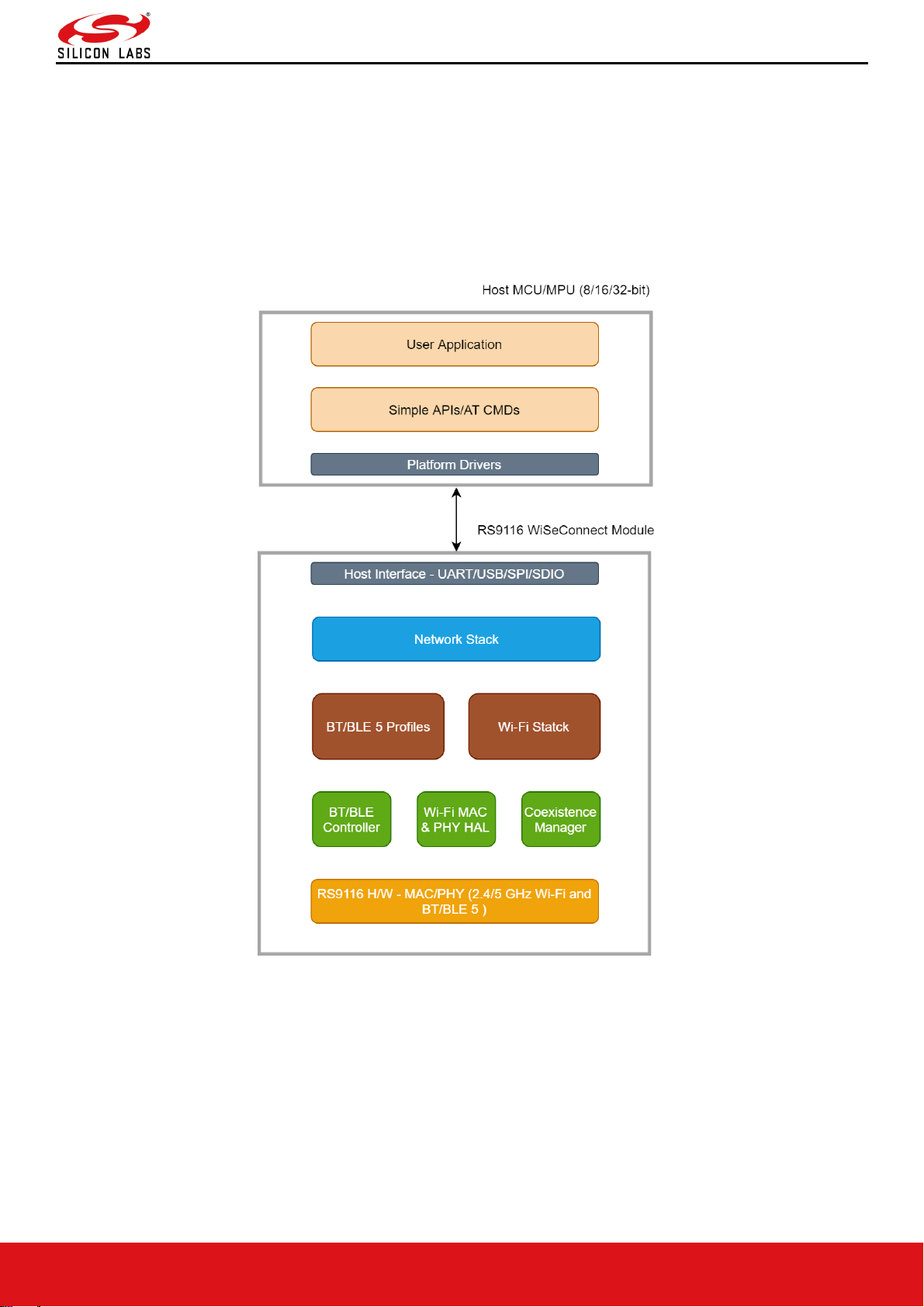
RS9116 WiSeConnect module includes Wi-Fi, TCP/IP and BT 5 stacks embedded in its internal flash memory. This
module requires a separate application processor which acts as a host.
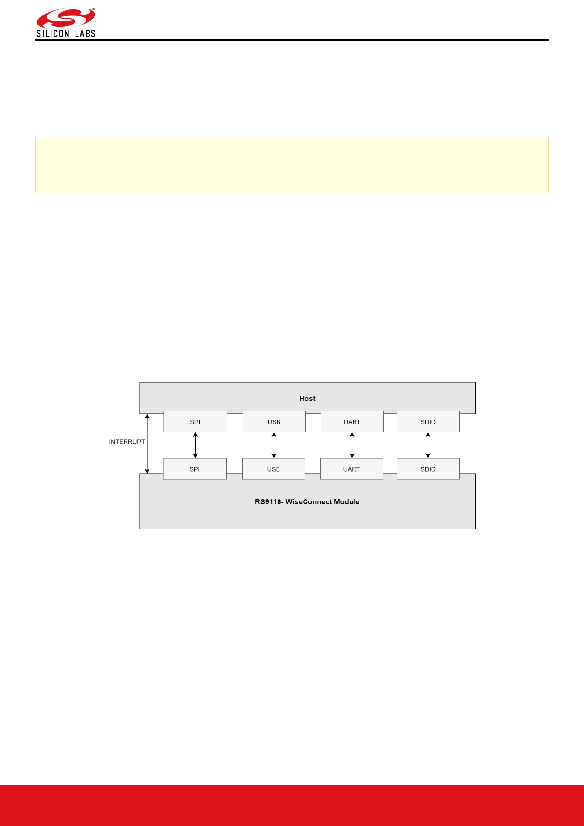
Host can communicate with RS9116 module using one of the interfaces listed below.
Figure 1: RS9116W Block Diagram
Page 7
RS9116W Wi-Fi AT Command Programming Reference Manual
Version 2.0
silabs.com | Building a more connected world. 7 | Page
RS9116 supports following interfaces for interacting with host.
• SPI
• UART
• USB
• SDIO
Note:
USB and SDIO interfaces are currently not supported.
Host can use either Simple APIs or AT Commands for configuring the module.
There are two modes for host interaction:
• AT Mode (ASCII)
In this mode, host should use AT Commands for interacting with RS9116 Module. This mode can be used only
with UART or USB-CDC interfaces. Section ‘AT Command Mode’ provides more details about this mode.
Section ‘WLAN Commands’ describes all commands and other required details.
• Binary Mode
In this mode, host should use Binary Commands for interacting with RS9116 Module. This mode can be used with
UART, SPI, USB and SDIO interfaces. Section ‘Binary Command Mode' provides more details about this mode.
Section ‘WLAN Commands’ describes all commands and other required details.
Host Interface block diagram is shown below,
Figure 2: RS9116W Host Interface Block Diagram
Page 8
RS9116W Wi-Fi AT Command Programming Reference Manual
Version 2.0
silabs.com | Building a more connected world. 8 | Page
1.2 WLAN Architecture
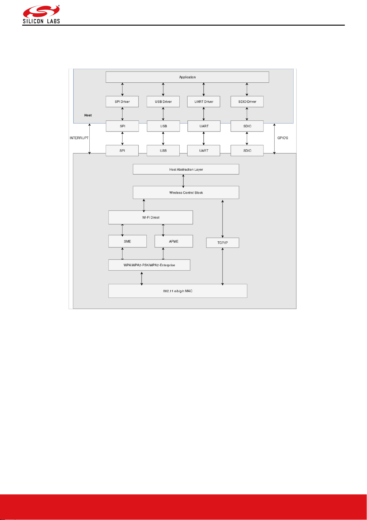
The following figure depicts the WLAN software architecture of the RS9116-WiSeConnect.
Figure 3: RS9116W Software Architecture
Application
The application layer invokes Simple APIs or AT Commands provided by SPI/ UART/USB/SDIO driver. The
application developer can use these APIs to build wireless applications.
SPI
The SPI interface on the RS9116-WiSeConnect works in slave mode. It is a 4-wire interface. In addition to the SPI
interface, the module provides additional interrupt pin to signal events to the host.
The interrupt is raised by the module in SPI mode for the following condition.
• When the module has data in its output buffer, it indicates host by raising active high signal on the interrupt pin.
The interrupt from module is active high and host must configure the interrupt in level trigger mode.
USB
The USB interface on the RS9116-WiSeConnect transmits/receives data to/from the Host in USB mode.
UART
The UART interface on the RS9116-WiSeConnect transmits/receives data to/from the Host in UART mode.
SDIO
The SDIO interface on the RS9116-WiSeConnect transmits/receives data to/from the Host in SDIO mode.
Page 9

RS9116W Wi-Fi AT Command Programming Reference Manual
Version 2.0
silabs.com | Building a more connected world. 9 | Page
Host Abstraction Layer (HAL)
The HAL abstracts the lower layers in the Host interface to which the RS9116-WiSeConnect is connected. The HAL
interacts with the Wireless Control Block layer for the processing of the frames obtained from or destined to the Host.
Wireless Control Block (WCB)
The data from/to the Host is classified as Wi-Fi specific frames or TCP/IP specific frames. The functionality of the
WCB module depends on the type and direction of the frames.
Wi-Fi Control Frames (WCF)
The WCB interprets the Wi-Fi control information from the Host and interacts with the SME (Station Management
Entity) or APME (Access Point Management Entity) based on operating mode of RS9116-WiSeConnect.
Configuration of the RS9116-WiSeConnect from the Host for Wi-Fi access is through AT commands or Binary
commands.
TCP/IP Control Frames
TCP/IP networking protocol provides end-to-end connectivity specifying how data should be formatted, addressed,
transmitted, routed and received at the destination.
If the packets received from the Host by WCB during transmission is interpreted as TCP/IP frames, then the WCB
interacts with TCP/IP stack for further processing before passing the packets to MAC layer. Similarly, if the packets
are received from the TCP/IP stack by WCB during reception then WCB processes by passing these packets to host.
Station Management Entity (SME)
The SME is the core layer which manages the Wi-Fi connectivity in Station mode. The SME maintains the state
machine to detect the activity on the Wi-Fi network and indicates to the user accordingly. It interacts with the WPA
supplicant if security is enabled in the Wi-Fi network.
Access point Management Entity (APME)
The APME is the core layer which manages the connectivity in Access Point group owner modes. The APME
maintains the state machine to handle multiple clients connected to the module. It interacts with WPA supplicant if
security is enabled in the Wi-Fi network.
WPA Supplicant
The main functionality of WPA supplicant is to support the key negotiation between Wi-Fi devices in a secure mode.
This functionality depends on the mode in which RS9116-WiSeConnect operates in Station mode, Access point
mode. The WPA supplicant is used to initiate the 802.1x/E Access Point authentication if WPA/WPA2-PSK is used as
the security parameter. It also plays a major part in performing the 4-way handshake to derive the PTK in
WPA/WPA2-PSK modes.
Page 10

RS9116W Wi-Fi AT Command Programming Reference Manual
Version 2.0
silabs.com | Building a more connected world. 10 | Page
2 Bootloader
This section briefs about features supported by the Network and Security Processor's (NWP) bootloader.
Basic Features
• Load default firmware
• Load selected firmware
• Upgrade firmware from the host
• Selecting default images
• Enable / Disable host interaction bypass
• Support for multiple host interfaces (SDIO/SPI/UART/USB/USB-CDC)
• Firmware integrity check
• Upgrading keys
• JTAG selection
The RS9116W supports two boot loading modes. They are:
1. Host interaction (Non-bypass) Mode: In this mode, the host can interact with the bootloader and can give boot
up options (commands) to configure different bootup operations. The host tells the module what operations it must
perform based on the selections made by the user.
2. Bypass mode: In this mode, bootloader interactions are completely bypassed and uses the stored bootup
configurations (which are selected in host interaction mode) & loads default firmware image in the module. This
mode is recommended for final production of software to minimize the bootup time.
Host Interaction Mode
In Host Interaction mode, host interaction varies based upon host interface. Host interaction in SPI/USB and
UART/USB-CDC are different. In UART & USB-CDC boot-up options are menu based. In SPI/USB, it uses command
exchanges. The details are explained in the below section.
Host Interaction Mode in UART / USB-CDC
This section explains the host interaction mode in the UART/USB CDC mode.
Startup Operation
After powering up, host is required to carry out ABRD (Auto baud rate detection) operation. After successful ABRD,
the module displays the menu of bootup options to host. The host needs to select the appropriate option.
Note:
On powerup, bootloader checks the integrity of the bootup options. If the integrity fails, it computes the integrity
from backup. If integrity passes, it copies the backup to the actual location. If the integrity of the backup options
also fails, the bootup options are reset/cleared. In either of the cases, bootloader bypass is disabled, or
corresponding error messages are given to host. In case of integrity failure and when the backup integrity check
passes, "LAST CONFIGURATION NOT SAVED" message is displayed. When backup integrity also fails,
“BOOTUP OPTIONS CHECKSUM FAILED" is displayed before displaying the bootup options.
Hyper Terminal Configuration
RS9116W uses the following UART interface configuration for communication:
Baud rate: The different baud rates supported by the module are: 9600 bps, 19200 bps, 38400 bps, 57600 bps,
115200 bps, 230400 bps, 460800 bps, 921600 bps.
Data bits: 8
Parity: None
Stop bits: 1
Flow control: None
Before the module is powered up, follow the sequence of steps given below:
Page 11
RS9116W Wi-Fi AT Command Programming Reference Manual
Version 2.0
silabs.com | Building a more connected world. 11 | Page
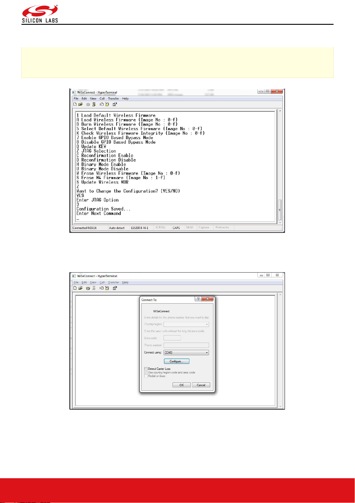
• Open Hyper terminal and enter any name in the "Name" field. After this, click "OK" button.
Here, "WiSeConnect" is entered as shown in the figure below.
Note:
Default baud rate of the module is 115200.
Figure 4: HyperTerminal Name Field Configuration
• After clicking "OK", the following dialog box is displayed as shown in the figure below.
Figure 5: HyperTerminal COM Port Field Configuration
• In the "Connect using" field, select appropriate com port. In the figure above COM3 is selected.
Click "OK" button.
Page 12
RS9116W Wi-Fi AT Command Programming Reference Manual
Version 2.0
silabs.com | Building a more connected world. 12 | Page
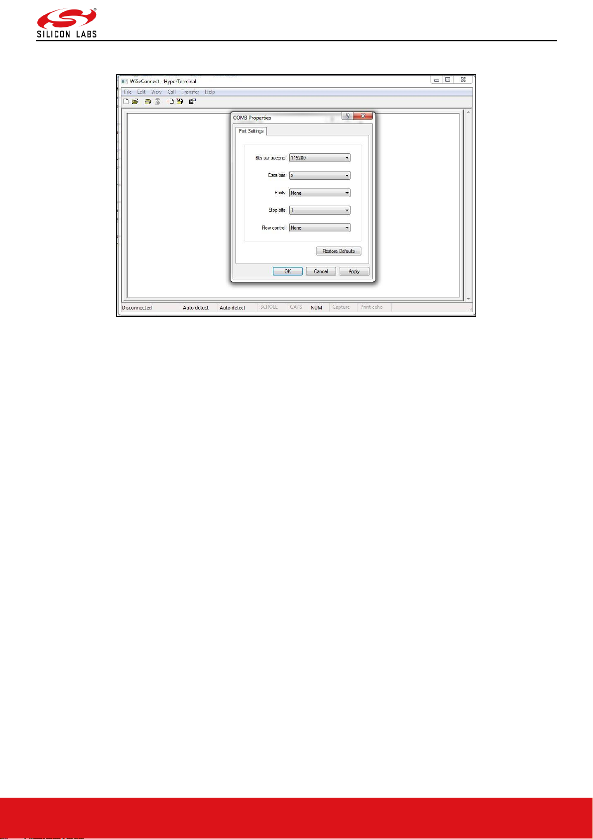
• After clicking the "OK" button the following dialog box is displayed as shown in the figure below.
Figure 6: HyperTerminal Baud Rate Field Configuration
Set the following values for different fields in figure 5 as given below.
• Set baud rate to 115200 in "Bits per second" field.
• Set Data bits to 8 in "Data bits" field.
• Set Parity to None in "Parity" field.
• Set stop bits to 1 in "Stop bits" field.
• Set flow control to None in "Flow control" field.
• Click "OK" button after entering the data in all the fields.
Auto Baud Rate Detection (ABRD)
The RS9116W automatically detects the baud rate of the Host's UART interface by exchanging some bytes. The Host
should configure the UART interface for the following parameters for ABRD detection.
RS9116W uses the following UART interface configuration for communication:
Baud Rate: The following baud rates are supported: 9600 bps, 19200 bps, 38400 bps, 57600 bps, 115200 bps,
230400 bps, 460800 bps, 921600 bps.
Data bits: 8
Stop bits: 1
Parity: None
Flow control: None
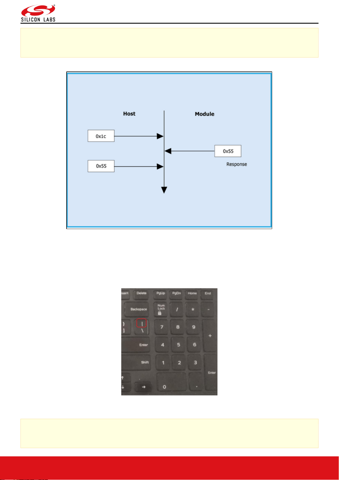
To perform ABRD on the RS9116W, the host must follow the procedure outlined below.
1. Configure the UART interface of the Host at desired baud rate.
2. Power on the RS9116W.
3. The Host, after releasing the module from reset, should wait for 20 ms for initial boot-up of the module to complete
and then transmit 0x1C at the baud rate to which its UART interface is configured. After transmitting '0x1C' to the
module, the Host should wait for the module to transmit 0x55 at the same baud rate.
4. If the '0x55' response is not received from the module, the host has to re-transmit 0x1C, after a delay of 200ms.
5. After finally receiving '0x55', the host should transmit '0x55' to the module. The module is now configured with the
intended baud rate.
Page 13
RS9116W Wi-Fi AT Command Programming Reference Manual
Version 2.0
silabs.com | Building a more connected world. 13 | Page
Note:
Performing ABRD in host interaction mode is must for USB CDC mode.
Figure 7: ABRD Exchange between Host and Module
Below are the bootup options, Firmware upgrade and Firmware loading procedures for WiSeConnect Product.
Start-Up Messages on Power-Up
After powering up the module, do the ABRD process by giving "shift + | " followed by 'U'. Pipe symbol is shown below,
you will see a welcome message on the host, followed by boot up options:
Figure 8: Pipe Symbol on Keyboard
Note:
Windows Hyper Terminal is used to demonstrate the boot up /up-gradation procedure.
Page 14
RS9116W Wi-Fi AT Command Programming Reference Manual
Version 2.0
silabs.com | Building a more connected world. 14 | Page
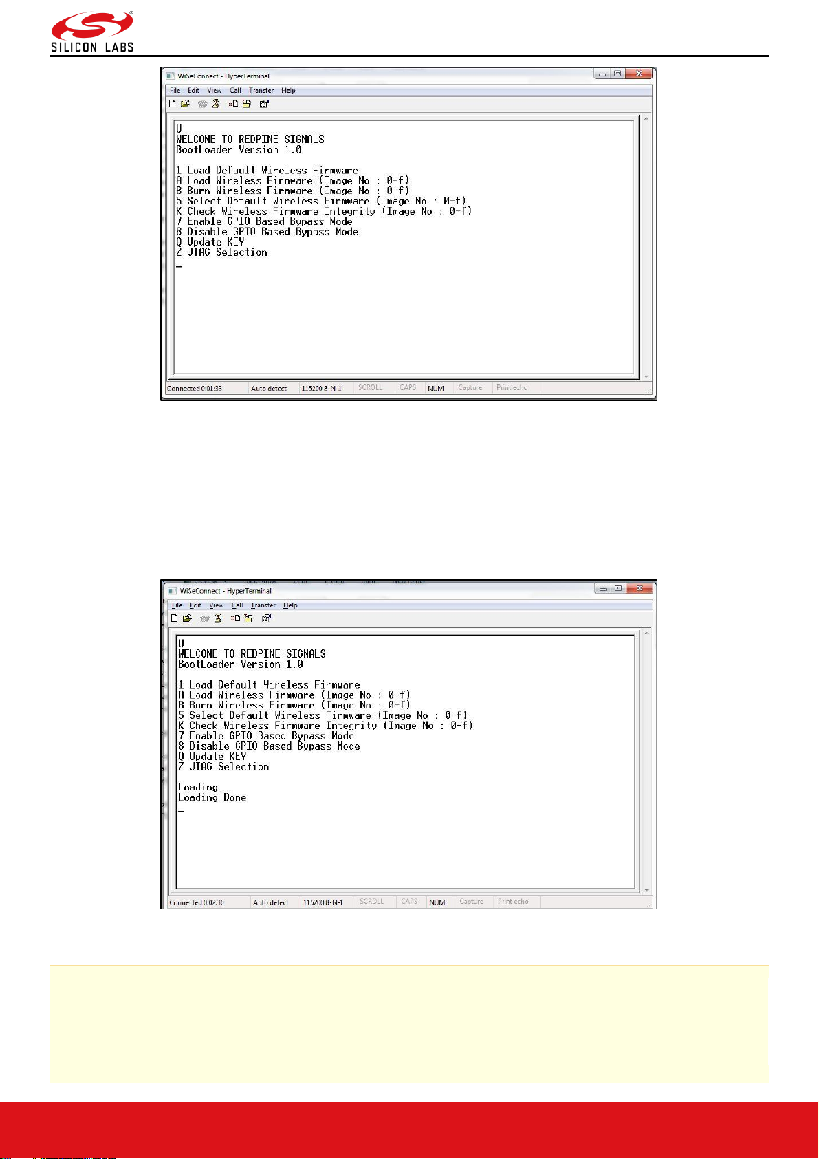
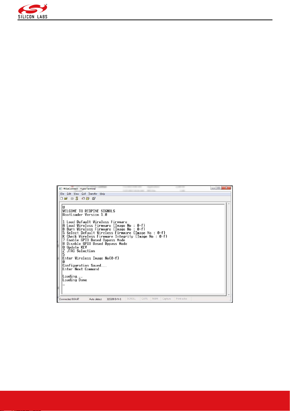
Figure 9: RS9116-WiSeConnect Module UART / USB-CDC Welcome Message
Loading the Default Wireless Firmware in the Module
To load the default firmware flashed onto the module, choose Option 1: "Load Default Wireless Firmware ".
Load Default Wireless Firmware
• After the welcome message is displayed as shown in the above figure, select option 1 "Load Default Wireless
Firmware" for loading Image.
Figure 10: RS9116-WiSeConnect Module UART / USB-CDC Default Firmware Loaded
Note:
By default, the module will be configured in AT mode. If mode switch from AT plus command mode to binary
mode is required, then user must give 'H' in the bootloader options.
The module lasts in the binary mode unless it changed to AT plus command mode and vice-versa.
To change from binary mode to AT mode, then user must give 'U' in the bootloader options.
Page 15
RS9116W Wi-Fi AT Command Programming Reference Manual
Version 2.0
silabs.com | Building a more connected world. 15 | Page
Loading selected Wireless Firmware in the Module
To load the selected firmware (from flash) onto the module, choose Option A: "Load Wireless Firmware (Image No: 0-
f)".
Load Wireless Firmware
• After the welcome message is displayed as shown in the above figure, select option A "Load Wireless Firmware
(Image No: 0-f)" for loading Image.
• In response to the option A, Module asks to Enter Image No.
• Select the image number to be loaded from flash.
• After successfully loading the default firmware, "Loading Done" message is displayed.
• After firmware loading is completed, the module is ready to accept commands.
Note:
1. In order to use host bypass mode, the user must select one of the images as default image by selecting
option 5 (Select Default Wireless Firmware).
2. In Host interaction mode, if no option is selected after bootup menu for 20 seconds then the bootloader will
load selected Wireless default image.
3. If the valid firmware is not present, then a message prompts "Valid firmware not present".
Firmware Upgradation
After powering up the module, a welcome message is displayed.
Upgrade NWP firmware Image
• After the welcome message is displayed, select option B "Burn Wireless Firmware (Image No: 0-f)" to upgrade
Wireless Image.
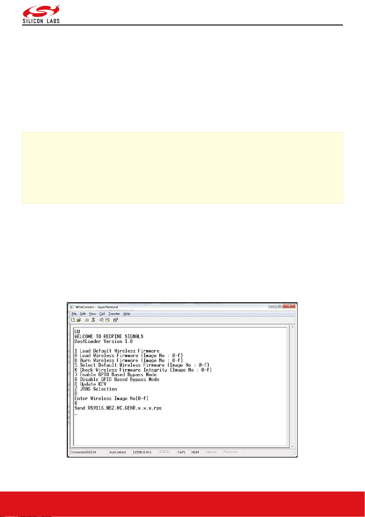
• The message "Enter Wireless Image No (0-f)" is displayed.
• Then select the Image no to be upgraded.
• The message "Send RS9116.NBZ.WC.GENR.x.x.x.rps" should appear as shown in the figure below.
Figure 11: RS9116-WiSeConnect Module Firmware Upgrade File Prompt Message
Page 16
RS9116W Wi-Fi AT Command Programming Reference Manual
Version 2.0
silabs.com | Building a more connected world. 16 | Page
Note:
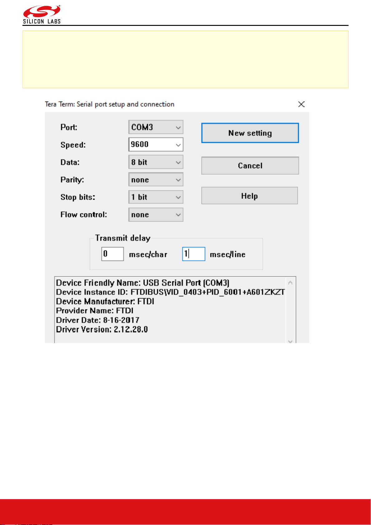
On faster machine using Tera Term it is recommended to configure transmit delay to avoid file transfer to
freeze.
After detection of serial port, change transmit delay from 0 msec/line to 1 msec/line to get 'firmware upgradation successful' as shown in the figure below.
Figure 12: Serial Port Setup and Connection
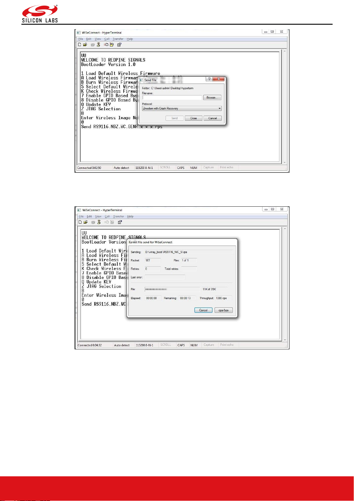
• In the "File" menu of HyperTerminal, select the "send file" option. A dialog box will appear as shown in the figure
below. Browse to the path where "RS9116.NBZ.WC.GENR.X.X.X.rps" is located and select Kermit as the protocol
option. After this, click the "Send" button to transfer the file.
• If the valid firmware is not present, then a message prompts "Valid firmware not present".
Page 17
RS9116W Wi-Fi AT Command Programming Reference Manual
Version 2.0
silabs.com | Building a more connected world. 17 | Page
Figure 13: RS9116-WiSeConnect Module Firmware Upgrade File Selection Message
• The dialog box message is displayed while file transfer is in progress as shown in the figure below.
Figure 14: RS9116-WiSeConnect Module Firmware Upgrade File Transfer Message
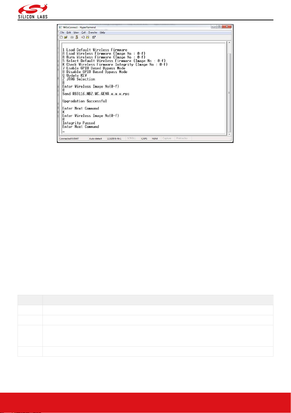
• After successfully completing the file transfer, module computes the integrity of the image and displays
"Upgradation Failed, re-burn the image" in case of failure. It displays "Upgradation Failed and default image
invalid, Bypass disabled" in case of both failure and corruption of the default image.
• In the case of success, module checks if the bootloader bypass is enabled and computes the integrity of the
default image selected. If the integrity fails, it sends "Upgradation successful, Default image invalid, gpio bypass
disabled." If integrity passes or GPIO bypass not enabled, it sends "Upgradation Successful" message on the
terminal as shown in the figure below.
Page 18
RS9116W Wi-Fi AT Command Programming Reference Manual
Version 2.0
silabs.com | Building a more connected world. 18 | Page
Figure 15: RS9116-WiSeConnect Module Firmware Upgrade Completion Message
• At this point, the upgraded firmware Image is successfully flashed to the module.
• The user can again cross check the integrity of the Image by selecting the Option K "Check Wireless Firmware
Integrity (Image No: 0-f)" for Wireless Image.
• Follow the steps mentioned in Loading the Default Wireless Firmware in the Module to load the firmware from
flash, select Option 1 from the above figure.
• The module is ready to accept commands from the Host.
Host Interaction Mode in SPI / USB
This section explains the exchange between host and module in host interaction mode (while bootloading) to select
different boot options through SPI / USB interfaces.
SPI Startup Operations1 SPI Startup Messages on Powerup
If the selected host interface is SPI or USB, the Bootloader uses two of the module hardware registers to interact with
the host. In the case of SPI host, these registers can be read or written using SPI memory read/write operations. In
case of USB host vendor, specific reads and writes on control endpoint is used to access these registers. Bootloader
indicates its current state through HOST_INTF_REG_OUT and host can give the corresponding commands by writing
onto HOST_INTF_REG_IN.
The significance of 4 bytes of the value written into HOST_INTF_REG_IN register is as follows:
Table 1: HOST_INTF_REG_IN Register Values
Nibble
Significance
Nibble[1:0]
Message code
Nibble[2]
Represents the Image number based on the command type
Nibble[3]
Represents the validity of the value in HOST_INTF_REG_IN register. Bootloader expects this value to be
0xA(HOST_INTERACT_REG_VALID). Bootloader validates the value written into this register if and only
if this value is 0xA
Nibble[7:4]
Represents Mode for JTAG selection
Page 19

RS9116W Wi-Fi AT Command Programming Reference Manual
Version 2.0
silabs.com | Building a more connected world. 19 | Page
Table 2: Bootloader Message Exchange Registers
Register Name
Memory Read/Write Address
HOST_INTF_REG_OUT
0x4105003C
HOST_INTF_REG_IN
0x41050034
PING Buffer
0x18000
PONG Buffer
0x19000
RSI_INT_MASK_REG_ADDR
0x41050000
Table 3: Bootloader Message Codes
Bootloader Interaction Messages
Message Codes
Message Codes in Hex
HOST_INTERACT_REG_IN_VALID
0xA000
HOST_INTERACT_REG_OUT_VALID
0xAB00
LOAD_DEFAULT_NWP_FW
'1'
0x31
LOAD_NWP_FW
'A'
0x41
BURN_NWP_FW
'B'
0x42
SELECT_DEFAULT_NWP_FW
'5'
0x35
ENABLE_GPIO_BASED_BYPASS
'7'
0x37
DISABLE_GPIO_BASED_BYPASS
'8'
0x38
CHECK_NWP_INTEGRITY
'K'
0x4B
KEY_UPDATE
'Q'
0x51
JTAG_SELECTION
'Z'
0x5A
LOAD_DEFAULT_NWP_FW_ACTIVE_LOW
0x71
LOAD_NWP_FW_ACTIVE_LOW
0x72
SELECT_DEFAULT_NWP_FW_ACTIVE_LOW
0x75
EOF_REACHED
'E'
0x45
PING_BUFFER_VALID
'I'
0x49
PONG_BUFFER_VALID
'O'
0x4F
POLLING_MODE
'P'
0x50
DISABLE_FWUPGRADE
'T'
0x54
ENABLE_FWUPGRADE
'N'
0x4E
Table 4: Bootloader Response Codes
Bootloader Interaction Messages
Response Codes
Response Codes in Hex
LOADING_INITIATED
'1'
0x31
VALID_FIRMWARE_NOT_PRESENT
'#'
0x23
SEND_RPS_FILE
'2'
0x32
UPGRADATION_SUCCESFULL
'S'
0x53
Page 20

RS9116W Wi-Fi AT Command Programming Reference Manual
Version 2.0
silabs.com | Building a more connected world. 20 | Page
Bootloader Interaction Messages
Response Codes
Response Codes in Hex
PONG_AVAIL
'O'
0x4F
PING_AVAIL
'I'
0x49
CMD_PASS 0xAA
CMD_FAIL 0xCC
FLASH_MEM_CTRL_CRC_FAIL
0xF1
FLASH_MEM_CTRL_BKP_CRC_FAIL
0xF2
INVALID_CMD
0xF3
UPGRADATION_SUCCESFULL_INVALID_DEFAULT_IMAGE
0xF4
INVALID_DEFAULT_IMAGE
0xF5
UPGRADATION_FAILED_INVALID_DEFAULT_IMAGE
0xF6
IMAGE_STORED_IN_DUMP (Safe Upgrade in Progress)
0xF7
FLASH_NOT_PRESENT
0xFA
IMAGE_INTEGRITY_FAILED
0xFB
BOOT_FAIL 0xFC
BOARD_READY
(BL_VER_HIGH << 4 |
BL_VER_LOW)
0x10
LAST_CONFIG_NOT_SAVED
0xF1
BOOTUP_OPTIONS_INTEGRITY_FAILED
0xF2
FWUP_BUFFER_VALID
0x5AA5
SPI Startup Messages on Powerup Table
Upon power-up, the HOST_INTF_REG_OUT register will hold value 0xABxx. Here 0xAB
(HOST_INTERACT_REG_OUT_VALID) signifies that the content of OUT register is valid. Bootloader checks for the
integrity of the bootup options by computing CRC. If the integrity fails, it checks the integrity from backup. If integrity
passes, it copies the backup to the actual location and writes (HOST_INTERACT_REG_OUT_VALID |
LAST_CONFIG_NOT_SAVED) in HOST_INTF_REG_OUT register. If the integrity of backup options also fails, the
bootup options are reset and (HOST_INTERACT_REG_OUT_VALID | BOOTUP_OPTIONS_INTEGRITY_FAILED) is
written in HOST_INTF_REG_OUT register. In either of the cases, bootloader bypass is disabled. If the bootup options
integrity passes, the HOST_INTF_REG_OUT register contains 0xABxx where xx represents the two nibble bootloader
version. This message is referred to as BOARD_READY indication throughout the document.
For instance, for bootloader version 1.0, the value of register will be 0xAB10. The host is expected to poll for one of
the three values and should give any succeeding command (based on error codes if present) only after reading the
correct value in HOST_INTF_REG_OUT reg.
Loading Default Wireless Firmware in the Module
The host can give options to bootloader to select the firmware load image type that will load the firmware from the
flash of the module.
Load Default Wireless Firmware
Upon receiving Board ready, if host wants to load default wireless firmware, it is expected to write value
(HOST_INTERACT_REG_IN_VALID | LOAD_DEFAULT_NWP_FW) or (HOST_INTERACT_REG_IN_VALID |
LOAD_DEFAULT_NWP_FW_ACTIVE_LOW) in HOST_INTF_REG_IN register. If the host command is
(HOST_INTERACT_REG_IN_VALID | LOAD_DEFAULT_NWP_FW) it is assumed that host platform is expecting
active high interrupts. If the command is (HOST_INTERACT_REG_IN_VALID |
LOAD_DEFAULT_NWP_FW_ACTIVE_LOW) it is assumed that the host is expecting active low interrupts and SPI
hardware will be configured accordingly. After sending this command host should wait for an interrupt for card ready
message from the loaded firmware.
Page 21

RS9116W Wi-Fi AT Command Programming Reference Manual
Version 2.0
silabs.com | Building a more connected world. 21 | Page
By default, Active high firmware will be selected by the Bootloader. To select the active low firmware, follow the
procedure after board ready is received.
• Read the RSI_INT_MASK_REG_ADDR register value
• Set BIT(9) in the read value and write back the value to the RSI_INT_MASK_REG_ADDR address
Note:
Hardware changes are required to support ACTIVE_LOW /ACTIVE_HIGH interrupts.
ACTIVE_LOW interrupt requires pull up on the interrupt pin.
ACTIVE_HIGH interrupt requires pull down on the interrupt pin.
Note:
For USB host interface mode interrupt configuration is not required, the host should send
(HOST_INTERACT_REG_IN_VALID | LOAD_DEFAULT_NWP_FW) to load default wireless Image.
Loading Selected Wireless Firmware in the Module
The host can give options to bootloader to select the firmware load image type which will load the firmware from the
flash of the module.
Load Selected Wireless Firmware
1. Upon receiving Board ready, if host wants to load a selected wireless firmware, it is expected to write value
(HOST_INTERACT_REG_IN_VALID | LOAD_NWP_FW | (IMAGE_NO << 8)) or
(HOST_INTERACT_REG_IN_VALID | LOAD_NWP_FW_ACTIVE_LOW | (IMAGE_NO << 8)) in
HOST_INTF_REG_IN register.
2. If host command is (HOST_INTERACT_REG_IN_VALID | LOAD_NWP_FW | (IMAGE_NO << 8)), it is assumed
that host platform is expecting active high interrupts.
3. If the command is (HOST_INTERACT_REG_IN_VALID | LOAD_DEFAULT_NWP_FW_ACTIVE_LOW), it is
assumed that the host is expecting active low interrupts and SPI hardware will be configured accordingly. After
sending this command host should wait for an interrupt for card ready message from the loaded firmware.
Note:
For USB host interface mode interrupt configuration is not required, host should send
(HOST_INTERACT_REG_IN_VALID | LOAD_NWP_FW | (IMAGE_NO << 8)) to load selected wireless Image.
Upgrading Wireless Firmware in the Module
With this option, host can select to upgrade the firmware in the flash of the module.
Upgrading Wireless Firmware
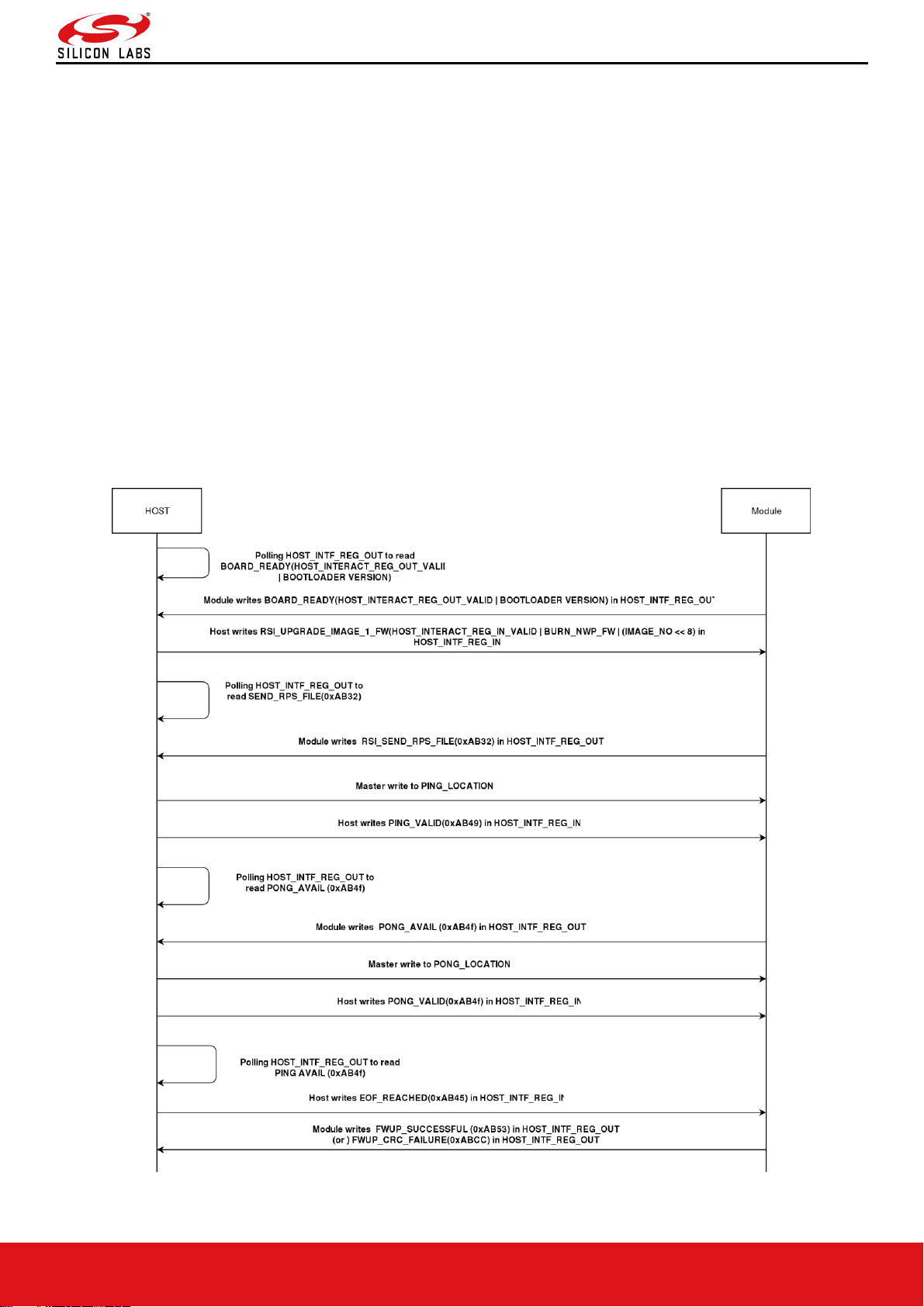
Steps for firmware upgradation sequence after receiving board ready are as follows.
1. After reading the valid BOARD_READY (i.e. HOST_INTERACT_REG_OUT_VALID | BOOTLOADER VERSION)
value in HOST_INTF_REG_OUT, host writes (HOST_INTERACT_REG_IN_VALID | BURN_NWP_FW |
(IMAGE_NO << 8) ) in HOST_INTF_REG_IN and host starts polling for HOST_INTF_REG_OUT.
2. Module polls for HOST_INTF_REG_IN register. When module reads a valid value (i.e.
HOST_INTERACT_REG_IN_VALID | BURN_NWP_FW | (IMAGE_NO << 8) ) in HOST_INTF_REG_IN, module
writes (HOST_INTERACT_REG_OUT_VALID | SEND_RPS_FILE) in HOST_INTF_REG_OUT.
3. When host reads valid value (i.e. HOST_INTERACT_REG_OUT_VALID | SEND_RPS_FILE) in
HOST_INTF_REG_OUT, host will write first 4Kbytes of firmware image in PING Buffer and writes (
HOST_INTERACT_REG_IN_VALID | PING_VALID) in HOST_INTF_REG_IN register. Upon receiving
PING_VALID command module starts burning this 4 Kbytes chunk onto the flash. When the module is ready to
receive data in PONG Buffer it sets value PONG_AVAIL (HOST_INTERACT_REG_OUT_VALID | PONG_AVAIL)
in HOST_INTF_REG_OUT. The host is required to wait for this value to be set before writing next 4Kbytes chunk
onto the module.
Page 22
RS9116W Wi-Fi AT Command Programming Reference Manual
Version 2.0
silabs.com | Building a more connected world. 22 | Page
4. On reading valid value (i.e. HOST_INTERACT_REG_OUT_VALID | PONG_AVAIL) in HOST_INTF_REG_OUT,
host starts memory write on PONG location and start polling for HOST_INTF_REG_OUT to read valid value (i.e.
HOST_INTERACT_REG_OUT_VALID | PING_AVAIL). Module reads (HOST_INTERACT_REG_OUT_VALID |
PONG_VALID) 0xAB4F value in HOST_INTF_REG_OUT and begin to write the data from PONG location into the
flash.
5. This write process continues until the host has written all the data into the PING-PONG buffers and there is no
more data left to write.
6. Host writes a (HOST_INTERACT_REG_IN_VALID | EOF_REACHED) into HOST_INTF_REG_IN register and
starts polling for HOST_INTF_REG_OUT.
7. On the other side module polls for HOST_INTF_REG_IN register. When module reads
(HOST_INTERACT_REG_IN_VALID | EOF_REACHED) in HOST_INTF_REG_IN, it computes integrity for entire
received firmware image. Then it checks if the bypass is enabled. If enabled, it checks for the validity of the
default image. If integrity is correct and default image is valid/GPIO bypass not enabled, module writes
(HOST_INTERACT_REG_OUT_VALID | FWUP_SUCCESSFUL) in HOST_INTF_REG_OUT register. If integrity
is correct and default image is invalid (bypass enabled), module writes (HOST_INTERACT_REG_OUT_VALID |
UPGRADATION_SUCCESFULL_INVALID_DEFAULT_IMAGE) in HOST_INTF_REG_OUT register and the
bypass is disabled. If the integrity is failed and default image is valid / GPIO bypass is not enabled, then the
module writes (HOST_INTERACT_REG_OUT_VALID | CMD_FAIL) in HOST_INTF_REG_OUT register. If the
integrity is failed and default image is invalid (bypass enabled), then the module writes (
HOST_INTERACT_REG_OUT_VALID | UPGRADATION_FAILED_INVALID_DEFAULT_IMAGE) in
HOST_INTF_REG_OUT register and the bypass is disabled.
Figure 16: Wireless Firmware Upgradation through SPI/USB
Page 23
RS9116W Wi-Fi AT Command Programming Reference Manual
Version 2.0
silabs.com | Building a more connected world. 23 | Page
GPIO Based Bootloader Bypass Mode for WiSeConnect Product
In GPIO based bootloader bypass mode host interactions with bootloader can be bypassed. There are two steps to
enable GPIO based Bootloader bypass mode:
1. The host needs to select default wireless image to load in bypass mode.
2. Enable Bootloader bypass mode.
3. Assert UULP_GPIO_2 to Bypass Bootloader upon powerup.
To enable Bootloader Bypass mode, host first has to give default image that has to be loaded in bypass mode and
select the bypass mode(enable). After rebooting the module, it goes to bypass mode and directly loads the default
firmware image.
Bypass Mode in UART / USB-CDC
Making Default Wireless Firmware Selection
With this option, host can select the default firmware image to be loaded.
Selecting a valid Image as the Default Image
• After the welcome message is displayed, user can select option 5 "Select Default Wireless Firmware (Image No:
0-f)".
• The message "Enter Wireless Image No. (0-f)" is displayed.
• Then select the Image number
• It is better to check the Integrity of Image before selecting it as Default Image.
• When default image is selected, module checks for the validity of the image selected and displays "Configuration
saved".
Figure 17: Making Image no - 0 as the Default Image
Enable/Disable GPIO Based Bypass Option
This option is for enabling or disabling the GPIO bootloader bypass mode.
Enabling the GPIO Based Bypass Mode
If user select option 7, GPIO based Bootloader bypass gets enabled. When this option is selected, module checks for
the validity of the image selected and displays "Configuration saved" if valid and "Default image invalid" if valid default
image is not present. Once enabled, from next bootup, Bootloader will latch the value of UULP_GPIO_2. If asserted, it
will bypass the whole boot loading process and will load the default firmware image selected.
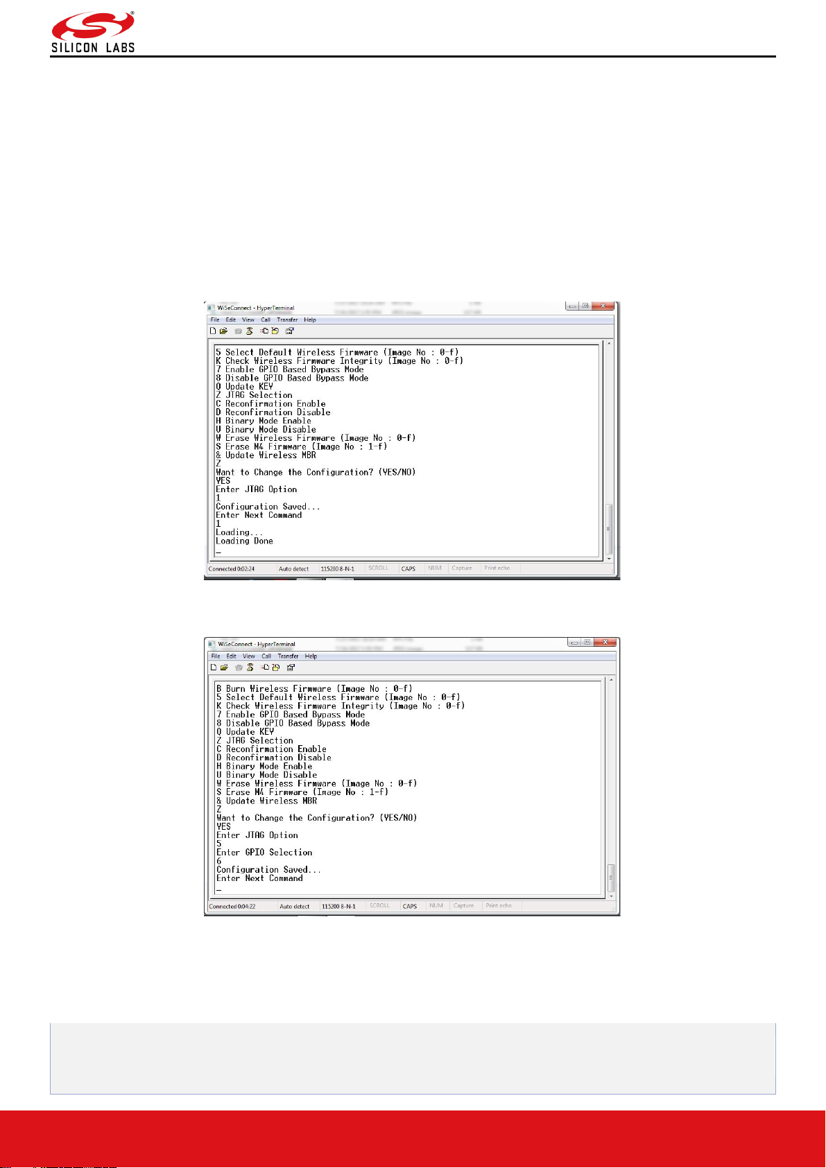
• After the welcome message is displayed, user can select option 5 "Select Default Wireless Firmware (Image No:
0-f)".
Page 24
RS9116W Wi-Fi AT Command Programming Reference Manual
Version 2.0
silabs.com | Building a more connected world. 24 | Page
• The message "Enter Wireless Image No. (0-f)" is displayed.
• Then select the Image no.
• It is better to check the Integrity of Image before selecting it as Default Image.
• When default image is selected, module checks for the validity of the image selected and displays "Configuration
saved".
• Then select option 7 to "Enable GPIO Based Bypass Mode"
• Module responds to select the host interface in Bypass mode ( 0 - UART, 1 - SDIO, 2 - SPI, 4 - USB, 5 - USB-
CDC)
• Select the required interface.
If the default image is valid, then it enables GPIO Bypass mode, otherwise it will not enable the GPIO Bypass mode.
Figure 18: Enabling the GPIO-based Bypass Mode: Valid Default Firmware
Figure 19: Enabling the GPIO-based Bypass Mode: Invalid Firmware
Disabling the GPIO Based Bypass Mode
• If the host selects option 8, GPIO based bypass gets disabled.
UULP_GPIO_2 needs to be de-asserted upon power up to move to host interaction mode, to select bootup
options like disable Bypass mode or to change the default image.
Page 25
RS9116W Wi-Fi AT Command Programming Reference Manual
Version 2.0
silabs.com | Building a more connected world. 25 | Page
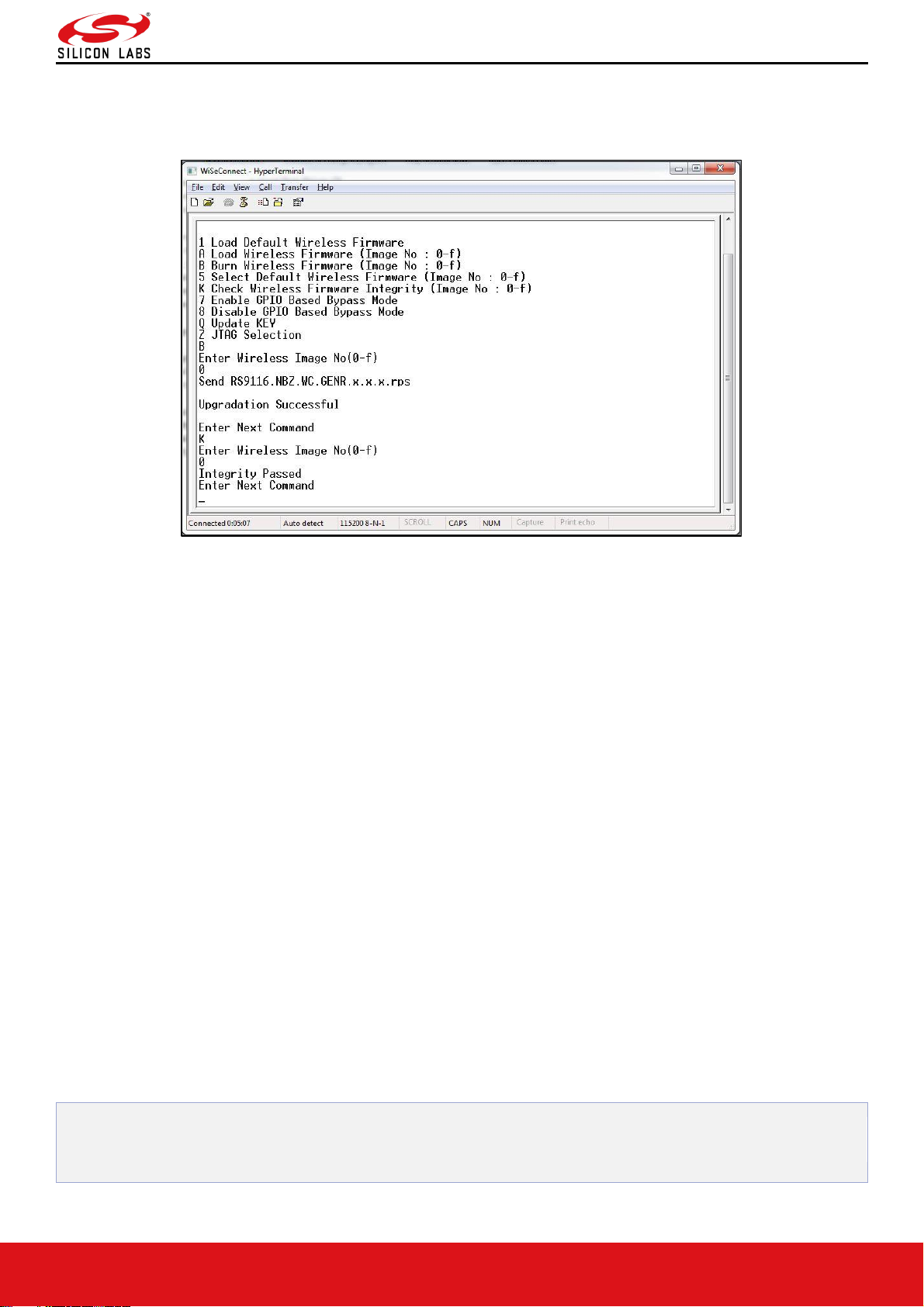
Check Integrity of the Selected Image
This option enables the user to check whether the given image is valid or not. When this command is given,
bootloader asks for the image for which integrity must be verified as shown in the figure below.
Figure 20: Integrity Check Passed
Bypass Mode in SPI / USB
Selecting the Default Image
1. Upon receiving Board ready, if host wants to select default functional image, it is expected to write value (
HOST_INTERACT_REG_IN_VALID | SELECT_DEFAULT_NWP_FW | (IMAGE_NO << 8) ) in
HOST_INTF_REG_IN register.
2. Host is expected to receive confirmation (HOST_INTERACT_REG_OUT_VALID | CMD_PASS) in
HOST_INTF_REG_OUT register if default image is valid. If default image is invalid,
(HOST_INTERACT_REG_OUT_VALID | CMD_FAIL) is written in HOST_INTF_REG_OUT register.
Enable/Disable GPIO Based Bootloader Bypass Mode
1. Upon receiving Board ready, if host wants to enable or disable GPIO based bypass mode, it is expected to write
value (HOST_INTERACT_REG_IN_VALID | ENABLE_GPIO_BASED_BYPASS) or
(HOST_INTERACT_REG_IN_VALID | DISABLE_GPIO_BASED_BYPASS) in HOST_INTF_REG_IN register.
2. Host expected to receive (HOST_INTERACT_REG_IN_VALID | ENABLE_GPIO_BASED_BYPASS) or
(HOST_INTERACT_REG_IN_VALID | DISABLE_GPIO_BASED_BYPASS) in HOST_INTF_REG_OUT register if
command is successful. If default image is invalid, (HOST_INTERACT_REG_OUT_VALID |
INVALID_DEFAULT_IMAGE) is written in HOST_INTF_REG_OUT register.
3. The host is expected to reboot the board after receiving confirmation (HOST_INTERACT_REG_IN_VALID |
ENABLE_GPIO_BASED_BYPASS) or (HOST_INTERACT_REG_IN_VALID
| DISABLE_GPIO_BASED_BYPASS) or (HOST_INTERACT_REG_OUT_VALID | INVALID_DEFAULT_IMAGE)
in HOST_INTF_REG_OUT register.
4. If GPIO based bypass is enabled, from next bootup onwards, the bootloader will latch the state of UULP_GPIO_2.
5. If UULP_GPIO_2 is asserted, the bootloader will not give board ready and it will directly load the default functional
image selected.
UULP_GPIO_2 needs to be de-asserted on power up to move to host interaction mode, to select bootup
options like disable Bypass mode or to change the default image.
Page 26

RS9116W Wi-Fi AT Command Programming Reference Manual
Version 2.0
silabs.com | Building a more connected world. 26 | Page
Command Mode Selection
This section describes the AT command mode or Binary mode selection in UART and USB-CDC.
The command mode type is selected by the user which is either AT command mode or Binary mode
through bootloader options.
The module reads the command type from the Flash Memory Controller and parses the commands respectively.
Once the mode is selected, it will remain in the same mode until it is switched to the other mode. By default, the
module remains in AT command mode.
Other Operations
This section contains additional, less frequently used bootloader options.
Update KEY
Note:
This feature is not enabled in the current release.
JTAG Selection
Note:
This feature is not enabled in the current release.
Page 27

RS9116W Wi-Fi AT Command Programming Reference Manual
Version 2.0
silabs.com | Building a more connected world. 27 | Page
3 Host Interfaces
RS9116 WiSeConnect Module supports SPI, USB, UART and SDIO for interfacing to host. This section describes
UART interface in detail including the supported features, protocols and commands.
Only UART and USB-CDC interfaces are supported in AT mode.
Note:
USB and SDIO interfaces are currently not supported.
3.1 UART Interface
This section describes RS9116-WiSeConnect UART interface, including the commands and processes to operate the
module via UART.
UART on the RS9116-WiSeConnect is used as a host interface to configure the module to send data and to receive
data.
Features
• Supports hardware (RTS/CTS) flow control.
• Supports following list of baud rates,
o 9600 bps
o 19200 bps
o 38400 bps
o 57600 bps
o 115200 bps
o 230400 bps
o 460800 bps
o 921600 bps
Note:
For baud rates greater than 115200, it is mandatory to enable UART hardware flow control.
Hardware Interface
RS9916W uses TTL serial UART at an operating voltage of 3.3V.
Host UART device must be configured with the following settings:
• Data bits - 8
• Stop bits - 1
• Parity - None
• Flow control - None
Software Protocol
AT+ command mode
This section explains the procedure that the host needs to follow in order to send Wi-Fi commands frames to the
module and to receive responses from the module in AT+ command mode.
TX Operation
The Host uses TX operations:
1. To send management commands to the module from the Host.
Page 28
RS9116W Wi-Fi AT Command Programming Reference Manual
Version 2.0
silabs.com | Building a more connected world. 28 | Page
2. To send actual data to the module which is to be transmitted onto the air.
3. If the host receives error code indicating packet dropped, the host must wait for a while and send the next
command /data.
4. The host should send next data packet only if it receives "OK<number of bytes sent>" response for the previous
one.
Rx Operation
The RS9116W responds with either an 'OK' or 'ERROR' string, for Management or Data frames along with a result or
error code.
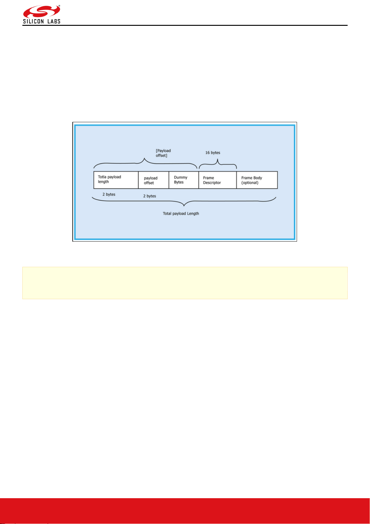
The module sends the response/received data to Host in a format as shown below:
Figure 21: RX Frame Format
Note:
If Payload offset is 'x', 'x-4' dummy bytes will be added before Frame Descriptor.
The host should follow the steps below to read the frame from the Module:
Read 4 bytes using Frame read.
1. Decode Total payload length and payload offset.
2. Read remaining payload by sending Frame to read with (total payload length – 4 bytes), discard dummy bytes and
then decode Frame descriptor and Frame Body.
Page 29

RS9116W Wi-Fi AT Command Programming Reference Manual
Version 2.0
silabs.com | Building a more connected world. 29 | Page
4 AT Command Mode
The Wi-Fi AT command set represents the frames that are sent from the Host to operate the RS9116WWiSeConnect. The command set resembles the standard AT command interface used for modems.
• All AT commands start with "at" and are terminated with a carriage return('\r') and a new line('\n') character.
• The AT command set for the RS9116W-WiSeConnect starts with "at+rsi_" followed by the name of the command
and any relevant parameters.
• In some commands, a '?' character is used after the command to query data from the module.
Appendix C: Sample AT command sequences captures the sample flow of commands to configure the module in
various functional modes.
Syntax of AT command:
at+rsi_<command_name>[=][parameters][?]\r\n
Example:
at+rsi_command=< parameter1 >,< parameter2 >,< parameter3 >\r\n
Each parameter should be separated by comma (,).
Note:
1. All commands are issued from Host to module as a sequence of ASCII characters. All return messages from
module to Host consist of OK or ERROR strings, along with some return parameters. The return parameters
may be ASCII or Hex on a case by case basis. ERROR is accompanied by <Error code>.
2. A command should NOT be issued by the Host before receiving the response of a previously issued
command from the module.
RS9116W-WiSeConnect supports following host interfaces in AT Command mode:
• UART
• USB-CDC
The following protocols are supporting in AT Command mode
• WLAN
• BT/BLE
Page 30

RS9116W Wi-Fi AT Command Programming Reference Manual
Version 2.0
silabs.com | Building a more connected world. 30 | Page
5 WLAN Commands
The following sections explains RS9116-WiSeConnect commands, their parameters, their responses and relevance in
AT mode.
5.1 Set Operating Mode
Description:
This is the first command that needs to be sent from host after receiving card ready frame from RS9116W module.
This command configures the module in different functional modes.
Command Format:
AT Mode:
at+rsi_opermode=
<oper_mode>,<feature_bit_map>,<tcp_ip_feature_bit_map>,<custom_feature_bit_map>,<ext_custom_feature_bit_m
ap>,<
bt_feature_bit_map>,<ext_tcp_ip_feature_bit_map>,<ble_feature_bit_map>,<ble_coustom_ext_feature_bit_map>,<c
onfig_feature_bit_map>\r\n
Note:
• ext_custom_feature_bit_map gets enabled when BIT(31) is set to ‘1’ in custom_feature_bitmap
at+rsi_opermode=<oper_mode>,<feature_bit_map>,<tcp_ip_feature_bit_map>,<custom_feature_bitmap>,<ext
_custom_feature_bit_map>\r\n
• ext_tcp_ip_feature_bit_map gets enabled when BIT(31) is set to ‘1’ in tcp_ip_feature_bit_map
at+rsi_opermode=<oper_mode>,<feature_bit_map>,<tcp_ip_feature_bit_map>,<custom_feature_bitmap>,<ext
_tcp_ip_feature_bit_map>\r\n
• bt_feature_bit_map gets enabled when BIT(31) is set to ‘1’ in both custom_feature_bit_map and
ext_custom_feature_bit_map
at+rsi_opermode=<oper_mode>,<feature_bit_map>,<tcp_ip_feature_bit_map>,<custom_feature_bitmap>,<ext
_custom_feature_bit_map>,<bt_feature_bit_map>\r\n
• ble_feature_bit_map gets enabled when BIT(31) is set to 1 in custom_feature_bitmap,
ext_custom_feature_bit_map and bt_feature_bit_map
at+rsi_opermode=<oper_mode>,<feature_bit_map>,<tcp_ip_feature_bit_map>,<custom_feature_bitmap>,<ext
_custom_feature_bit_map>,<bt_feature_bit_map>,<ext_tcp_ip_feature_bit_map>,<ble_feature_bit_map>\r\n
• ble_custom_ext_feature_bit_map gets enable when BIT(31) is set to 1 in ble_custom_feature_bit_map
at+rsi_opermode=<oper_mode>,<feature_bit_map>,<tcp_ip_feature_bit_map>,<custom_feature_bitmap>,<ext
_custom_feature_bit_map>,<bt_feature_bit_map>,<ext_tcp_ip_feature_bit_map>,<ble_feature_bit_map>,<ble_
coustom_ext_feature_bit_map>\r\n
• config_feature_bit_map gets enabled when BIT(31) is set to '1' in both tcp_ip_feature_bit_map and
ext_tcp_ip_feature_bit_map
at+rsi_opermode=<oper_mode>,<feature_bit_map>,<tcp_ip_feature_bit_map>,<custom_feature_bitmap>,<ext
_custom_feature_bit_map>,<bt_feature_bit_map>,<ext_tcp_ip_feature_bit_map>,<ble_feature_bit_map>,<ble_
coustom_ext_feature_bit_map>,<config_feature_bit_map>\r\n
Oper_mode:
Sets the mode of operation. oper_mode contains two parts <wifi_oper_mode, coex_mode>. Lower two bytes
represents wifi_oper_mode and higher two bytes represents coex_modes.
oper_mode = ((wifi_oper_mode) | (coex_mode << 16))
Page 31

RS9116W Wi-Fi AT Command Programming Reference Manual
Version 2.0
silabs.com | Building a more connected world. 31 | Page
Wi-Fi_oper_mode values:
• 0 - Wi-Fi Client Mode.
The module works as a normal client that can connect to an Access Point with different security modes other than
enterprise security.
• 2 – Enterprise Security Client Mode.
The module works as a client that can connect to an Access Point with WPA/WPA2-Enterprise security.
• 6 – Access Point mode.
In this mode, the module acts as an Access Point, depending on the inputs supplied for the command "Configure
AP Mode". In Access Point mode, a Maximum of 16 clients can connect based on the bits set in custom feature bit
map selection in opermode.
• 8 - PER Mode.
This mode is used for calculating packet error rate and mostly used during RF certification tests.
• 9 – Concurrent mode.
This mode is used to run module in concurrent mode. In concurrent mode, host can connect to an AP and can
create AP simultaneously.
Note:
In concurrent mode,
1. AP MAC address's last byte will differ, and it will be one plus the station mode MAC last byte.
2. Maximum of 4 Station devices can be connected to Concurrent AP.
3. In TCP/IP non bypass mode, Broadcast / Multicast packet goes to first created interface (e.g. if Station mode
connects first, the broadcast / multicast packet goes to the network that belongs to station mode).
4. IPV6 support is not supported in the current release.
5. Aggregation is not supported.
Possible coex modes:
Coex_mode
Description
1
WLAN
2
ZigBee*
3
WLAN + ZigBee*
4
Bluetooth
5
WLAN + Bluetooth
6
Bluetooth + Zigbee co-existence*
7
WLAN + Bluetooth + ZigBee co-existence*
8
Dual Mode (Bluetooth and BLE)
9
WLAN + Dual Mode
10
Dual Mode + ZigBee co-existence*
11
WLAN + Dual Mode + ZigBee co-existence*
12
BLE mode
13
WLAN + BLE
14
BLE and ZigBee co-existence*
15
WLAN + BLE + ZigBee co-existence*
Page 32

RS9116W Wi-Fi AT Command Programming Reference Manual
Version 2.0
silabs.com | Building a more connected world. 32 | Page
Note:
1. Coex modes are supported only in 384K memory configuration
2. For WLAN Coex mode, AP mode scan is not allowed.
3. ZigBee is not currently supported. Will be supported in future releases.
If coex mode is enabled in opermode command, then BT / BLE protocol will start and give corresponding card
ready in parallel with opermode command response (which will be handled by corresponding application).
BT card ready frame is described in RS9116W BT Classic AT Command Programming Reference
Manual.pdf (available at https://docs.silabs.com/rs9116) and BLE card ready frame is described in
RS9116W BLE AT Command Programming Reference Manual.pdf (available at
https://docs.silabs.com/rs9116).
To select coex mode, please refer to RS9116_TCP_IP_Feature_Selection_vx.x.x.xlsx given in "Docs" folder
of the release package.
feature_bit_map: This bitmap is used to enable following WLAN features:
feature_bit_map
Functionality
Bit set to
0
Bit set to
1
Note and Info
feature_bit_map[0]
Open mode feature
Disable
Enable
Supported in client
mode.
feature_bit_map[1]
PSK security
Disable
Enable
Supported in client
mode.
feature_bit_map[2]
Aggregation
Disable
Enable
feature_bit_map[3]
LP GPIO handshake
Disable
Enable
feature_bit_map[4]
ULP GPIO handshake
Disable
Enable
feature_bit_map[5]
Reserved
Reserved
Reserved
feature_bit_map[6]
Reserved
Reserved
Reserved
feature_bit_map[7]
WPS support
Enable
Disable
feature_bit_map[8]
To support EAP-LEAP in WiFi + BT Coex
mode
Disable
Enable
feature_bit_map[9:31]
Reserved. Should set to be '0'
Note:
feature_bit_map[0], feature_bit_map[1] are valid only in Wi-Fi Client mode.
tcp_ip_feature_bit_map: To enable TCP/IP related features.
tcp_ip_feature_bit_map
Functionality
Bit set
to 0
Bit set
to 1
Note and Info
tcp_ip_feature_bit_map[0]
TCP/IP bypass
Disable
Enable
tcp_ip_feature_bit_map[1]
HTTP server
Disable
Enable
tcp_ip_feature_bit_map[2]
DHCPv4 client
Disable
Enable
tcp_ip_feature_bit_map[3]
DHCPv6 client
Disable
Enable
Page 33

RS9116W Wi-Fi AT Command Programming Reference Manual
Version 2.0
silabs.com | Building a more connected world. 33 | Page
tcp_ip_feature_bit_map
Functionality
Bit set
to 0
Bit set
to 1
Note and Info
tcp_ip_feature_bit_map[4]
DHCPv4 server
Disable
Enable
tcp_ip_feature_bit_map[5]
DHCPv6 server
Disable
Enable
tcp_ip_feature_bit_map[6]
Dynamic update of web
pages (JSON objects)
Disable
Enable
tcp_ip_feature_bit_map[7]
HTTP client
Disable
Enable
tcp_ip_feature_bit_map[8]
DNS client
Disable
Enable
tcp_ip_feature_bit_map[9]
SNMP agent
Disable
Enable
tcp_ip_feature_bit_map[10]
SSL
Disable
Enable
tcp_ip_feature_bit_map[11]
PING from module (ICMP)
Disable
Enable
tcp_ip_feature_bit_map[12]
HTTPS Server
Disable
Enable
Only supported in opermode 0.
tcp_ip_feature_bit_map[13]
Set to 0.
tcp_ip_feature_bit_map[14]
To send configuration details
to host on submitting
configurations on wireless
configuration page
Disable
Enable
tcp_ip_feature_bit_map[15]
FTP client
Disable
Enable
tcp_ip_feature_bit_map[16]
SNTP client
Disable
Enable
tcp_ip_feature_bit_map[17]
IPv6 mode
Disable
Enable
IPv6 will also get enabled if DHCP v6
client/DHCP v6 server is enabled
irrespective of
tcp_ip_feature_bit_map[17].
tcp_ip_feature_bit_map[18]
RAW Socket feature
Disable
Enable
This feature is supported only in AP
mode.
TCP_BYPASS feature should be
disabled for this feature to be
supported. If any packet from host with
frame type 0x1 is received by firmware,
the packet will be sent on air without
TCP/IP stack processing. ARP and
broadcast packets (other than DHCP
packets) which are coming on air will
be sent to host.
tcp_ip_feature_bit_map[19]
To MDNS and DNS-SD
Disable
Enable
tcp_ip_feature_bit_map[20]
SMTP client
Disable
Enable
tcp_ip_feature_bit_map[21:24]
To select no of sockets
tcp_ip_feature_bit_map[25]
Single SSL socket
Disable
Enable
tcp_ip_feature_bit_map[26]
Private & Public certificate
Disable
Enable
If Secure handshake is with CA –
certificate alone, then disable loading
private and public keys and erase
these certificates from the flash using
load_cert API.
Or if Secure handshake is needed for
verification of Private and Public keys,
then enable loading of private and
public keys.
Page 34

RS9116W Wi-Fi AT Command Programming Reference Manual
Version 2.0
silabs.com | Building a more connected world. 34 | Page
tcp_ip_feature_bit_map
Functionality
Bit set
to 0
Bit set
to 1
Note and Info
tcp_ip_feature_bit_map[27]
SSL certificate on to the
RAM
Disable
Enable
tcp_ip_feature_bit_map[28]
TCP-IP data packet Dump on
UART2
Disable
Enable
tcp_ip_feature_bit_map[29]
POP3 client
Disable
Enable
tcp_ip_feature_bit_map[30]
To enable OTAF (On the Air
Firmware) up gradation.
Disable
Enable
tcp_ip_feature_bit_map[31]
tcp_ip_ext_feature_bitmap
validity
Disable
Enable
Note:
Feature selection utility is provided in the release package. WiSeConnect device supports the selected features
combination only if it is feasible as per WiSeConnect_TCPIP_Feature_Selection_vx.x.x.xlsx.
custom_feature_bit_map:This bitmap is used to enable following custom features
custom_feature_bit_map
Functionality
Bit set
to 0
Bit set
to 1
Note and Info
custom_feature_bit_map[2]
If this bit is set to '1', the DHCP server
behavior, when the module is in AP mode
changes. The DHCP server, when it assigns
IP addresses to the client nodes, does not
send out a Gateway address, and sends
only the assigned IP and Subnet values to
the client. It is highly recommended to keep
this value at '0' as the changed behavior is
required in only very specialized use cases
and not in normal AP functionality. The
default value of this bit is '0'.
custom_feature_bit_map[4]
To run NWP (Network Processor) at Higher
clock frequency(160MHZ)
Disable
Enable
Need to set pll_mode to 1
in feature frame
command.
custom_feature_bit_map[5]
Hidden SSID in AP mode
Disable
Enable
custom_feature_bit_map[6]
DNS server IP address in DHCP offer
response in AP mode.
Disable
Enable
custom_feature_bit_map[8]
DFS channel passive scan support
Disable
Enable
it's mandatory to set
region before scanning
DFS channel.
custom_feature_bit_map[10]
Asynchronous messages to host to indicate
the module state.
Disable
Enable
custom_feature_bit_map[11]
Packet pending wake on wireless indication
in UART mode
Disable
Enable
custom_feature_bit_map[12]
Bypass AP Blacklist in client mode
Disable
Enable
By default, client
maintains AP blacklist
internally to avoid some
access points. To bypass
AP blacklist feature in
client mode during
roaming or rejoin, this
Page 35

RS9116W Wi-Fi AT Command Programming Reference Manual
Version 2.0
silabs.com | Building a more connected world. 35 | Page
custom_feature_bit_map
Functionality
Bit set
to 0
Bit set
to 1
Note and Info
feature should be
enabled.
custom_feature_bit_map[17]
To select between de-authentication or null
data (with power management bit set)
based roaming.
Depending on selected method station, it
will send de-auth or Null data to the
connected AP when roaming from
connected AP to the newly selected AP.
Disable
Enable
custom_feature_bit_map[18]
Reserved
custom_feature_bit_map[19]
Reserved
custom_feature_bit_map[20]
Trigger Auto Configuration
Disable
Enable
custom_feature_bit_map[22]
Used to enable per station power save
packet buffer limit in AP mode.
When enabled, only two packets per station
will be buffered when station is in power
save
Disable
Enable
custom_feature_bit_map[23]
HTTP/HTTPs authentication
Disable
Enable
custom_feature_bit_map[24]
To run NWP at Higher clock
frequency(120MHZ)
Disable
Enable
Need to set pll_mode to 1
in feature frame command
custom_feature_bit_map[25]
HTTP server credentials to host in get
configuration command
Disable
Enable
custom_feature_bit_map[26]
To accept or reject new connection request
when maximum clients are connected in
case of LTCP.
Disable
Enable
By default, this bit value is
zero.
When BIT[26] is zero:
For a LTCP socket when
maximum clients are
connected if a new
connection request is
received, then this
connection request will
not be rejected. Instead
module will maintain this
connection request in
LTCP pending list.
This request will be
served when any of the
connected client is
disconnected.
When BIT[26] is set:
For a LTCP socket when
maximum clients are
connected if a new
connection request is
received, then this
connection request will be
rejected immediately.
Module will not maintain
this connection request in
LTCP pending list.
custom_feature_bit_map[27]
Dual band roaming and vcsafd feature
Disable
Enable
Page 36

RS9116W Wi-Fi AT Command Programming Reference Manual
Version 2.0
silabs.com | Building a more connected world. 36 | Page
custom_feature_bit_map
Functionality
Bit set
to 0
Bit set
to 1
Note and Info
custom_feature_bit_map[28]
Real time clock from host
Disable
Enable
custom_feature_bit_map[29]
IAP support in BT mode
Disable
Enable
custom_feature_bit_map[31]
ext_custom_feat_bitmap validity
Disable
Enable
BIT[0:1], BIT[3:4], BIT[7], BIT[21], BIT[30]: Reserved, should be set to all '0'.
Note:
For UART / USB-CDC in AT mode:
When user does not give any tcp_ip_feature_bit_map value then default settings for client mode, Enterprise
client mode.
HTTP server, DHCPv4 client, DHCPv6 client and JSON objects are enabled.
When user does not give any tcp_ip_feature_bit_map value then default settings for Access point mode are:
HTTP server, DHCPv4 server, DHCPv6 server and JSON objects are enabled.
Parameters- feature_bit_map, tcp_ip_feature_bit_map and custom_feature_bit_map are optional in opermode
command in UART mode for AT mode.
If user does not give these parameters then default configuration gets selected, as explained above, based
upon the operating mode configured.
If opermode is 8 (PER mode is selected) - feature_bit_map, tcp_ip_feature_bit_map and
custom_feature_bit_map can be ignored or not valid. Set to zero.
ext_custom_feature_bit_map:
This feature bitmap is an extension of custom feature bitmap and is valid only if BIT[31] of custom feature bitmap is
set. This enables the following feature.
ext_custom_feature_bit_
map
Functionality
Bit set
to 0
Bit set
to 1
Note and Info
ext_custom_feature_bit_ma
p[0]
Antenna diversity feature.
Disable
Enable
ext_custom_feature_bit_ma
p[1]
4096-bit RSA key support
Disable
Enable
This bit is required to set
for 4096-bit RSA key
support. If key size is
4096-bit, module will use
software routine for
exponentiation, so
connection time will
increase.
ext_custom_feature_bit_ma
p[3]
SSL certificate with 4096-bit key support
Disable
Enable
ext_custom_feature_bit_ma
p[4]
This bit is applicable only in AP and
concurrent AP mode. If this bit is set, the
module will send broadcast data (if any)
immediately without waiting for DTIM.
Disable
(AP
sends
broadc
ast
packet
at
DTIM
only.)
Enable
(Enable
sending
broadc
ast
without
waiting
for
DTIM)
If this bit is enabled, then
connected client who is in
power save may miss the
packet.
Page 37

RS9116W Wi-Fi AT Command Programming Reference Manual
Version 2.0
silabs.com | Building a more connected world. 37 | Page
ext_custom_feature_bit_
map
Functionality
Bit set
to 0
Bit set
to 1
Note and Info
ext_custom_feature_bit_ma
p[5]
Pre authentication Support.
Disable
Enable
ext_custom_feature_bit_ma
p[6]
40MHZ Support
Disable
Enable
11J AP don't support
40MHZ
Note:
40MHz is not
supported.
ext_custom_feature_bit_ma
p[9]
EXT_HTTP_SKIP_DEFAULT_LEADING_C
HARACTER
To skip default leading character ("\") in
resource name
ext_custom_feature_bit_ma
p[11]
802.11R Over the Air Roaming Support
Disable
Enable
1.Resource Request
Support is not Present.
2 If both BIT[11] and
BIT[16] are not enabled
then it will select as
Legacy Roaming.
ext_custom_feature_bit_ma
p[12]
802.11J support.
Disable
Enable
If this bit is enabled, set
region command is
mandatory with setting it
to Japan region and band
value must be 1 (5GHz).
ext_custom_feature_bit_ma
p[13]
802.11W support.
Disable
Enable
ext_custom_feature_bit_ma
p[14]
TLS Multiple versions Support in SSL.
Disable
Enable
ext_custom_feature_bit_ma
p[15]
Support 16 Stations in AP Mode.
If this bit is enabled, then
16 stations can connect
in AP mode otherwise
Maximum of 8 stations
can connect.
ext_custom_feature_bit_ma
p[16]
802.11R Over the Distributed System
Roaming Support
1. Resource Request
Support is not Present.
2. If both BIT[11] and
BIT[16] are not enabled
then it will select as
Legacy Roaming.
ext_custom_feature_bit_ma
p[19]
Low power mode in GPIO based or M4
based ULP power save
ext_custom_feature_bit_ma
p[20:21]
Default memory configuration (RAM) is
192KB. User can set these bits to change
the memory configuration as below:
MODE(KB)
BIT[20]
BIT[21]
192 0 0
Page 38

RS9116W Wi-Fi AT Command Programming Reference Manual
Version 2.0
silabs.com | Building a more connected world. 38 | Page
ext_custom_feature_bit_
map
Functionality
Bit set
to 0
Bit set
to 1
Note and Info
256 0 1
320 1 0
384 1 1
ext_custom_feature_bit_ma
p[22:23]
To configure Sleep clock source selection
To select sleep clock for TA (Thread Arc
processor), either crystal clock or RC clock
SELECTION
BIT[23]
BIT[22]
Use RC clock as sleep
clock
0
0
Use 32KHz clock from
external XTAL
OSCILLATOR
0
1
Use 32KHz bypass clock
on UULP_GPIO_3
1
0
Use 32KHz bypass clock
on UULP_GPIO_4
1
1
If BIT[23] is set '1' and
BIT[22] is set to '0'
in ext_custom_feature_bi
t_map, then user has to
use UULP_GPIO_0 for
sleep indication to host.
ext_custom_feature_bit_ma
p[24]
Reserved
ext_custom_feature_bit_ma
p[25]
To enable 1.8v supply for TA
Disable
Enable
ext_custom_feature_bit_ma
p[26]
To enable 3.3v supply for TA
Disable
Enable
ext_custom_feature_bit_ma
p[27]
To select UART port for NWP (Network
Processor) debug prints
Disable
(Enable
debug
prints
on
UART
2)
Enable
(Enable
debug
prints
on
UART
1 and is
applica
ble only
if Host
Interfac
e is not
UART)
By default, all the debug
prints from NWP will be
coming on UART2 if this
bit is not enabled.
UART 1 pins are mapped
to the following pins w.r.t
to NWP. User needs to
ensure that these pins
are not used in MCU
applications in WiSeMCU
mode to avoid conflicts of
pins usage based on the
requirement. This bit is
valid only if BIT[28] in
ext_custom_feature_bit_
map is set to 0.
UART 1 - TX: GPIO_9
RX: GPIO_8
UART 2 - TX: GPIO_6
RX: GPIO_10
There is no functionlaity
on rx pins for debug
prints.
ext_custom_feature_bit_ma
p[28]
UART debug prints from NWP
Disable
(Enable
debug
prints)
Enable
(Disabl
e
debug
By default, this bit value
is zero.
When BIT[26] is zero: For
a LTCP socket when
Page 39

RS9116W Wi-Fi AT Command Programming Reference Manual
Version 2.0
silabs.com | Building a more connected world. 39 | Page
ext_custom_feature_bit_
map
Functionality
Bit set
to 0
Bit set
to 1
Note and Info
prints
on
either
UART1
or
UART2
)
maximum clients are
connected if a new
connection request is
received, then this
connection request will
not be rejected. Instead
module will maintain this
connection request in
LTCP pending list.
This request will be
served when any of the
connected client is
disconnected.
When BIT[26] is set: For
a LTCP socket when
maximum clients are
connected if a new
connection request is
received, then this
connection request will be
rejected immediately.
Module will not maintain
this connection request in
LTCP pending list.
ext_custom_feature_bit_ma
p[29:30]
Reserved
ext_custom_feature_bit_ma
p[31]
BT and BLE feature_bit_map validity
Disable
Enable
ext_tcp_ip_feature_bit_map
ext_tcp_ip_feature_bit_map
Functionality
Bit set
to 0
Bit set
to 1
Note and Info
ext_tcp_ip_feature_bit_map[1]
DHCP USER CLASS
Disable
Enable
ext_tcp_ip_feature_bit_map[2]
HTTP server root path
bypass
Disable
Enable
ext_tcp_ip_feature_bit_map[3]
Correcting the ACK
sequence number in the
TCP packet
retransmission path
Disable
Enable
Need to enable this bit if user wants to
run the bi-directional data transfer.
ext_tcp_ip_feature_bit_map[4]
To enable TCP ACK
division factor feature
Disable
Enable
ext_tcp_ip_feature_bit_map[5]
To enable SSL server
certificate validation by
host.
Disable
Enable
ext_tcp_ip_feature_bit_map[6]
Support for SSL 16K
record size
Disable
Enable
ext_tcp_ip_feature_bit_map[7]
To enable
DNS_CLIENT_BYPASS
by host
Disable
Enable
Page 40

RS9116W Wi-Fi AT Command Programming Reference Manual
Version 2.0
silabs.com | Building a more connected world. 40 | Page
ext_tcp_ip_feature_bit_map
Functionality
Bit set
to 0
Bit set
to 1
Note and Info
ext_tcp_ip_feature_bit_map[8]
To enable TCP window
scaling feature
Disable
Enable
If user wants to use more than 64Kb
window size.
tcp_rx_window_size_cap in socket
config command is used to increase
the window size.
ext_tcp_ip_feature_bit_map[9]
To enable Dual Mode
feature
Disable
Enable
Enabling this feature allows to use both
bypass and non-bypass modes
simultaneously.
ext_tcp_ip_feature_bit_map[10]
To enable Ethernet Wi-Fi
bridge feature
Disable
Enable
ext_tcp_ip_feature_bit_map[11]
To enable the dynamic
coex memory
Disable
Enable
To enable or disable the coex and
update TCP RX window accordingly.
ext_tcp_ip_feature_bit_map[12:15]
To select the no of
selects
Disable
Enable
ext_tcp_ip_feature_bit_map[16]
To enable socket wait
close
Disable
Enable
If it is set socket will not be closed until
the shutdown is called from host.
Note:
Refer to 'rsi_shutdown()' API in
RS9116W SAPI Programming
Reference Manual at
https://docs.silabs.com/rs9116/
Note:
It is recommended to enable this
bit, when using TCP sockets.
ext_tcp_ip_feature_bit_map[17]
To enable MQTT feature
Disable
Enable
If user wants to use AT command for
MQTT, should be enable this bit in the
Opermode Command
ext_tcp_ip_feature_bit_map[18]
To enable HTTP OTAF
Feature
Disable
Enable
To do firmware upgrade with http this
bit should be enabled
ext_tcp_ip_feature_bit_map[19:29]
Reserved
ext_tcp_ip_feature_bit_map[30]
To configure additional
memory for SSL
connection typically to a
cloud server
Disable
Enable
If user connects to a cloud server using
two SSL connections, then it is
required to set this bit to avoid 0xD2
error
ext_tcp_ip_feature_bit_map[31]
config_feature_bit_map
validity
Disable
Enable
Note:
1.Set BIT(31) in tcp_ip_feature_bit_map & BIT(29) in ext_tcp_ip_feature_bit_map to open 3 SSL sockets.
2. Three SSL Feature is supported only in Opermode WLAN Only Mode.
bt_feature_bit_map
Page 41

RS9116W Wi-Fi AT Command Programming Reference Manual
Version 2.0
silabs.com | Building a more connected world. 41 | Page
This bitmap is valid only if BIT[31] of extended custom feature bit map is set.
bt_feature_bit_map
Functionality
Bit set to 0
Bit set to 1
Note and Info
bt_feature_bit_map[0-14]
Reserved
bt_feature_bit_map[15]
HFP profile bit enable
Disable
Disable
bt_feature_bit_map[16:19]
Reserved for future use
bt_feature_bit_map[20:22]
number of slaves supported by BT
Maximum no of BT slaves: 1
bt_feature_bit_map[23]
A2DP profile bit enable
Disable
Enable
bt_feature_bit_map[24]
A2DP profile role selection
Disable
Enable
bt_feature_bit_map[25]
A2DP accelerated mode selection
Disable
Enable
bt_feature_bit_map[26]
A2DP i2s mode selection
Disable
Enable
bt_feature_bit_map[27:29]
Reserved
bt_feature_bit_map[30]
RF Type selection
Disable
Enable
bt_feature_bit_map[31]
Validate ble feature bit map
Disable
Enable
ble_feature_bit_map
This bitmap is valid only if BIT[31] of bt custom feature bit map is set.
ble_feature_bit_map
Functionality
Bit set to 0
Bit set to 1
Note and Info
ble_feature_bit_map[0:7]
BLE nbr of attributes,
Maximum No of Ble attributes =
80,
Please refer NOTE given below
for more info.
ble_feature_bit_map[8:11]
BLE Nbr of GATT services
maximum no services - 10
Please refer NOTE given below
for more info.
ble_feature_bit_map[12:15
]
BLE Nbr of slaves
Maximum No of Ble slaves = 8
Please refer NOTE given below
for more info.
ble_feature_bit_map[16:23
]
BLE tx power index
Give 31 as ble tx power index
(e.g. 31<<16).
This variable is used to select the
ble tx power index value. The
following are the possible values.
Default Value for BLE Tx Power
Index is 31
Range for the BLE Tx Power
Index is 1 to 75 (0, 32 indices are
invalid)
1 - 31 BLE -0DBM Mode
33 - 63 BLE- 10DBM Mode
64- 75 BLE - HP Mode.
ble_feature_bit_map[24:26
]
BLE powersave options
BLE_DUTY_CYCLING
BIT(24)
BLR_DUTY_CYCLING
BIT(25)
Page 42

RS9116W Wi-Fi AT Command Programming Reference Manual
Version 2.0
silabs.com | Building a more connected world. 42 | Page
ble_feature_bit_map
Functionality
Bit set to 0
Bit set to 1
Note and Info
BLE_4X_PWR_SAVE_MO
DE BIT(26)
ble_feature_bit_map[27:29
]
Reserved
ble_feature_bit_map[30]
RS9113 - RS9116
compatible features
Disable
Enable
ble_feature_bit_map[31]
Reserved
ble_custom_ext_feature_bit_map:
This bitmap is valid only if BIT[31] of ble custom feature bit map is set.
ble_coustom_ext_feature_bit_map
Functionality
Bit set
to 0
Bit set
to 1
Note and Info
ble_coustom_ext_feature_bit_map[0:4]
BLE nbr of Connection
Events
ble_coustom_ext_feature_bit_map[5:12]
BLE nbr of record size in
bytes (n)
E.g.: n*16:(n=60, default 1024
bytes(1K))
ble_coustom_ext_feature_bit_map[13]
GATT INIT
0 - GATTt Init in Firmware
1 - GATT Init in Host
Note:
If bit bt_custom_feature_bit_map[31] is set:
1. User can enter maximum of 8 BLE slaves.
2. Maximum of 10 services in total can exist out of which two services namely GAP and GATT are added by
default. So, if this bitmap has value 10 user can add up to 8 services.
3. Maximum of 80 attributes in total can exist out of which ten attributes of GAP and GATT are added by
default. So, if this bitmap has value 80 user can add up to 70 attributes.
If bit bt_custom_feature_bit_map is not set:
1. Default number of BLE slaves supported is 3.
2. Maximum of 5 services in total can exist out of which two services namely GAP and GATT are added by
default. So, user can add up to 3 services.
3. Maximum of 20 attributes in total can exist out of which ten attributes of GAP and GATT are added by
default. So, user can add up to 10 attributes.
config_feature_bit_map:
This bitmap is valid only if BIT[31] of ext_tcp_ip_feature_bit_map is set.
config_feature_bit_map
Functionality
Bit set
to 0
Bit set
to 1
Note and Info
config_feature_bit_map[0]
To select wakeup indication to host.
Disable
Enable
Page 43

RS9116W Wi-Fi AT Command Programming Reference Manual
Version 2.0
silabs.com | Building a more connected world. 43 | Page
config_feature_bit_map
Functionality
Bit set
to 0
Bit set
to 1
Note and Info
If it is disabled UULP_GPIO_3 is used as a
wakeup indication to host.
If it is enabled UULP_GPIO_0 is used as a
wakeup indication to host.
config_feature_bit_map[5:2]
BIT
(5)
BIT(
4)
BIT(
3)
BIT(
2)
BT
Volt
age
Wi-Fi
Volta
ge
Description
0 0 0 0 Default
configuration.
Voltages are
based on BIT(25)
in
ext_custom_feat
ure_bit_map, if
this bit is set to 1
means 1.8v
selected else
3.3v selected
0 0 0 1 3.1V 3.1V
Fixed voltage
operation 3.1V
for BT and Wi-Fi.
0 0 1 0 1.85V 1.85V
Fixed voltage
operation 1.85V
for BT and Wi-Fi.
0 0 1 1 1.85V 3.1V
Protocol based
PA Voltage
switching
between BT and
Wi-Fi – Option1
0 1 0 0 1.55V 3.1V
Protocol based
PA Voltage
switching
between BT and
Wi-Fi – Option2
0 1 0 1 1.55
V/1.
85V
1.85V
/3.1V
NOTE: It's not
supported Yet.
Adaptive PA
voltage switching
based on
Protocol and
Wireless channel
conditions
BT 1.85V when
far from headset
– otherwise
1.55V
Wi-Fi 1.85V
when near AP –
otherwise 3.1V
These bits are
used for dynamic
voltage selection
Page 44

RS9116W Wi-Fi AT Command Programming Reference Manual
Version 2.0
silabs.com | Building a more connected world. 44 | Page
config_feature_bit_map
Functionality
Bit set
to 0
Bit set
to 1
Note and Info
config_feature_bit_map[9:6]
BIT
(6)
BIT
(7)
BIT
(8)
BIT
(9)
Description
0 0 0 0 0 means INTERNAL_PMU
0 0 0 1 EXTERNAL_PMU_GOOD_
TIME_100USEC
0 0 1 0 EXTERNAL_PMU_GOOD_
TIME_200USEC
0 0 1 1 EXTERNAL_PMU_GOOD_
TIME_300USEC
0 1 0 0 EXTERNAL_PMU_GOOD_
TIME_400USEC
0 1 0 1 EXTERNAL_PMU_GOOD_
TIME_500USEC
0 1 1 0 EXTERNAL_PMU_GOOD_
TIME_600USEC
0 1 1 1 EXTERNAL_PMU_GOOD_
TIME_700USEC
1 0 0 0 EXTERNAL_PMU_GOOD_
TIME_800USEC
1 0 0 1 EXTERNAL_PMU_GOOD_
TIME_900USEC
1 0 1 0 EXTERNAL_PMU_GOOD_
TIME_1000USEC
1 0 1 1 EXTERNAL_PMU_GOOD_
TIME_1100USEC
1 1 0 0 EXTERNAL_PMU_GOOD_
TIME_1200USEC
1 1 0 1 EXTERNAL_PMU_GOOD_
TIME_1300USEC
1 1 1 0 EXTERNAL_PMU_GOOD_
TIME_1400USEC
1 1 1 1 EXTERNAL_PMU_GOOD_
TIME_1500USEC
These bits are
used to select
external PMU good
time.
1 to 15 means
100usec to
1500usec
(in100usec
granularity)
config_feature_bit_map[11:10]
BIT(11)
BIT(10)
Description
0 1 if this set External LDO Enable
1 1 If this set External LDO is 1.0v,
Else External LDO is 1.1v (This
field valid only if External LDO
is enabled i.e. 10bit is set)
These bits are
used for External
LDO selection
External PMU:
1.In case of
External PMU,
User has to
set EXTERNAL_P
MU_GOOD_TIME_
CONFIGURATION
value to external
PMU good time, if
this is zero then it
Page 45

RS9116W Wi-Fi AT Command Programming Reference Manual
Version 2.0
silabs.com | Building a more connected world. 45 | Page
config_feature_bit_map
Functionality
Bit set
to 0
Bit set
to 1
Note and Info
indicates using
Internal PMU.
2. In case of
External PMU 1.0v
or 1.05v, User has
to set both the
bits config_feature_
bit_map[11]
& config_feature_bi
t_map[10].
config_feature_bit_map[13:12]
BIT(13)
BIT(
12)
Description
0 0 UULP_GPIO_0 as sleep
indication to host.
0 1 ULP_GPIO_6 as sleep
indication to host.
1 1 ULP_GPIO_5 as sleep
indication to host
If these bits are not
set, then by default
UULP_GPIO_0 will
be used.
config_feature_bit_map[14]
To select TLS 1.0 version
Disable
Enable
config_feature_bit_map[15]
To select TLS 1.2 version
Disable
Enable
config_feature_bit_map[16]
Active high or low interrupt mode selection for
wake on wireless operation
If it is disabled active low interrupt is used in
wake on wireless operation.
If it is enabled active high interrupt is used in
wake on wireless operation.
Disable
Enable
config_feature_bit_map[31:17]
Reserved
Note:
32KHz external clock connection and power save pins
As per Silicon lab's datasheet update in May 2019, the 32KHz external clock and the power save pins
connections have changed. To keep SW compatibility between initial design (i.e. first EVKs developed by
Silicon labs) as well as new designs, there are currently 2 options for connecting the 32KHz external clock and
the power save pins:
Option 1:
External 32KHz clock connection pins : XTAL_32KHZ_P & XTAL_32KHZ_N
Power Save connection pins : HOST_BYP_ULP_WAKEUP & UULP_VBAT_GPIO_3
Option 2:
External 32KHz clock connection pin : UULP_VBAT_GPIO_3
Power Save connection pins : HOST_BYP_ULP_WAKEUP & UULP_VBAT_GPIO_0
As per Silicon's labs datasheet updated in May'2019, Option 2 must be used for External 32KHz external clock
and Power save connections in new designs.
Page 46

RS9116W Wi-Fi AT Command Programming Reference Manual
Version 2.0
silabs.com | Building a more connected world. 46 | Page
Response:
AT Mode:
Result Code
Description
OK
Successful execution of the command
ERROR<Error code>
Failure
Possible error codes:
Possible error codes are 0x0021,0x0025,0xFF73,0x002C,0xFF6E,0xFF6F,0xFF70,0xFFC5.
Example:
AT Mode:
When only oper_mode is given in command:
at+rsi_opermode=1\r\n
0x61 0x74 0x2B 0x72 0x73 0x69 0x5F 0x6F 0x70 0x65 0x72 0x6D 0x6F 0x64 0x65 0x3D 0x31 0x0D 0x0A
Response:
OK\r\n
0x4F 0x4B 0x0D 0x0A
When other parameters along with mode_val is given in opermode command:
at+rsi_opermode=1,1,2,0\r\n
0x61 0x74 0x2B 0x72 0x73 0x69 0x5F 0x6F 0x70 0x65 0x72 0x6D 0x6F 0x64 0x65 0x3D 0x31 0x2C 0x31 0x2C 0x32
0x2C 0x30 0x0D 0x0A
By giving above command module is configured in WFD mode with HTTP server enabled in open mode.
Note:
Enabling Aggregation bit (feature_bit_map[2]) and Low power mode bit (ext_custom_feature_bit_map[19]) in
Opermode will result in Wi-Fi data not working. So, they cannot be enabled at the same time.
5.2 Band
Description:
This command configures the band in which the module must be configured. This command must be issued after
opermode command.
Command Format:
AT Mode:
at+rsi_band=< bandVal >\r\n
Command Parameters:
The valid values for the parameter for this command are as follows:
bandVal(1 byte):
Mode
Functionality
0
2.4 GHz
1
5 GHz
2
Dual band (2.4 Ghz and 5 Ghz)
Note:
1. Dual band is supported in station mode.
Page 47

RS9116W Wi-Fi AT Command Programming Reference Manual
Version 2.0
silabs.com | Building a more connected world. 47 | Page
Note:
802.11J support only 5 GHz bandVal
Response:
AT Mode:
Result Code
Description
OK
Successful execution of the command
ERROR<Error code>
Failure
Possible error codes:
Possible error codes are 0x0005, 0x0021, 0x0025, 0x002C, 0x003c.
Relevance:
This command is relevant in all operating modes.
Example:
AT Mode:
at+rsi_band=0\r\n
0x61 0x74 0x2B 0x72 0x73 0x69 0x5F 0x62 0x61 0x6E 0x64 0x3D 0x30 0x0D 0x0A
Response:
OK\r\n
0x4F 0x4B 0x0D 0x0A
5.3 WLAN Config
Description:
This command configures WLAN parameters.
Command Format:
AT Mode:
at+rsi_config=< config_type >,< config_val >\r\n
Command Parameters:
The valid values for the parameter for this command are as follows:
The valid values for the parameter for this command are as follows:
Config_type[2 bytes]: 1 - To configure RTS threshold value
Config_value[2 bytes]: [256-2346] - Range of rts threshold value
Note:
Only RTS_THRESHOLD is supported.
Note:
rsi_config command must be given after rsi_init command.
Response:
AT Mode:
Result Code
Description
OK
Successful execution of the command
Page 48

RS9116W Wi-Fi AT Command Programming Reference Manual
Version 2.0
silabs.com | Building a more connected world. 48 | Page
Result Code
Description
ERROR<Error code>
Failure
Possible error codes:
Possible error codes are 0x0063, 0x0064.
Relevance:
This command is relevant in all operating modes.
Example:
AT Mode:
at+rsi_config=1,256\r\n
0x61 0x74 0x2B 0x72 0x73 0x69 0x5F 0x63 0x6F 0x6E 0x66 0x69
0x67 0x3D 0x31 0x2C 0x32 0x35 0x36 0x0D 0x0A
Response:
OK\r\n
0x4F 0x4B 0x0D 0x0A
5.4 Set MAC Address
Description:
This command sets the module's MAC address. This command has to be issued before band command.
Command:
AT Mode:
at+rsi_setmac=< macAddr >\r\n
Command Parameters:
macAddr[6 bytes] – Mac address to be set for module.
Note:
In concurrent mode, given MAC is applied to station mode and AP mode MAC address last byte will differ from
station mode MAC.
AP mode MAC address last byte will be one plus the station mode MAC address last byte given by host.
Response:
AT Mode:
Result Code
Description
OK
Successful execution of the command
ERROR<Error code>
Failure
Possible error codes:
Possible error codes are 0x0021, 0x0025, 0x002C.
Relevance:
This command is relevant in all operating modes.
Example:
AT Mode:
at+rsi_setmac=001122334455\r\n
0x61 0x74 0x2B 0x72 0x73 0x69 0x5F 0x73 0x65 0x74 0x6D 0x61 0x63 0x3D 0x30 0x30 0x31 0x31 0x32 0x32 0x33
0x33 0x34 0x34 0x35 0x35 0x0D 0x0A
Response:
OK\r\n
0x4F 0x4B 0x0D 0x0A
Page 49

RS9116W Wi-Fi AT Command Programming Reference Manual
Version 2.0
silabs.com | Building a more connected world. 49 | Page
5.5 Init
Description:
This command programs the module's Baseband and RF components and returns the MAC address of the module to
the host. This command has to be issued after band command.
Command:
AT Mode:
at+rsi_init\r\n
Command Parameters:
No parameters
Response:
AT Mode:
Result Code
Description
OK<macAddress>
macAddress (6 bytes, Hex)
ERROR<Error code>
Failure
Response Parameters:
macAddress[6 byte]: The MAC address of the module.
Possible error codes:
Possible error codes are 0x0021, 0x0025, 0x002C,0x0002.
Relevance:
This command is relevant in all operating modes
Example:
AT Mode:
at+rsi_init\r\n
0x61 0x74 0x2B 0x72 0x73 0x69 0x5F 0x69 0x6E 0x69 0x74 0x0D 0x0A
Response:
FOR NON-CONCURRENT MODE:
OK<MAC_Address>\r\n
OK 0x00 0x23 0xA7 0x13 0x14 0x15\r\n
0x4F 0x4B 0x00 0x23 0xA7 0x13 0x14 0x15 0x0D 0x0A
FOR CONCURRENT MODE:
Response:
AT Mode:
Result Code
Description
OK <macAddress1> <macAddress2>
macAddress(6 bytes Hex ) macAddress(6 bytes Hex )
ERROR<Error code>
Failure
Response Parameters:
macAddress[6 bytes]: The MAC address for two interfaces of the module.
Possible error codes:
Possible error codes are 0x0021, 0x0025, 0x002C,0x0002.
Relevance:
This command is relevant in all operating modes
Example:
AT Mode:
at+rsi_init\r\n
0x61 0x74 0x2B 0x72 0x73 0x69 0x5F 0x69 0x6E 0x69 0x74 0x0D 0x0A
Response:
OK<MAC_Address1><MAC_Address2>\r\n
Page 50

RS9116W Wi-Fi AT Command Programming Reference Manual
Version 2.0
silabs.com | Building a more connected world. 50 | Page
OK 0x00 0x23 0xA7 0x13 0x14 0x15 0x00 0x23 0xA7 0x13 0x14 0x16\r\n
0x4F 0x4B 0x00 0x23 0xA7 0x13 0x14 0x15 0x00 0x23 0xA7 0x13 0x14 0x16 0x0D 0x0A
5.6 User Configurable Gain Table
Description:
This command is used to configure gain table to the module from user. This method is used for overwriting default
gain tables that are present in firmware. This command has to be issued immediate to init command. Customer can
load all the three gain tables (i.e., 2.4GHz-20Mhz, 5GHz-20Mhz) one after other by changing band and bandwidth
values.
Note:
This frame has to be used by customers who has done FCC/ETSI/KCC certification with their own antenna. All
other customers should not use this. Inappropriate use of this frame may result in violation of FCC/ETSI/KCC or
any certifications and Silicon labs is not liable for that.
Command:
AT Mode:
at+rsi_gain_table=<Band>,<Bandwidth>,<payload_len>,<payload>\r\n
Command Parameters:
Band[1 byte]:
Mode
Functionality
1
2.4 GHz
2
5 GHz
Bandwidth:
Mode
Functionality
0
20 MHz
1
40 MHz
Note:
40MHz is not supported.
Payload_len:
1) Max table size in 2.4Ghz is 128 bytes
2) Max table size in 5Ghz is 64bytes.
Payload: pass channel gain values for different regions in the mentioned format.
Gain Table Payload Format:
1. Gain table Format for 2.4G Band: (Each entry of the table is 1 byte)
<TABLE NAME>[] = {
<NO.of Regions>,
<REGION NAME 1>, <CHANNEL_CODE_2G>,
<CHANNEL NUMBER 1>, <MAX POWER FOR b RATE>, <MAX POWER FOR g RATE>, <MAX POWER
FOR n RATE>,
<CHANNEL NUMBER 2>, <MAX POWER FOR b RATE>, <MAX POWER FOR g RATE>, <MAX POWER
Page 51

RS9116W Wi-Fi AT Command Programming Reference Manual
Version 2.0
silabs.com | Building a more connected world. 51 | Page
FOR n RATE>,
.
.
<CHANNEL NUMBER m-1>, <MAX POWER FOR b RATE>, <MAX POWER FOR g RATE>, <MAX POWER
FOR n RATE>,
<CHANNEL NUMBER m>, <MAX POWER FOR b RATE>, <MAX POWER FOR g RATE>, <MAX POWER
FOR n RATE>,
<REGION NAME 2>, <CHANNEL_CODE_2G>,
<CHANNEL NUMBER 1>, <MAX POWER FOR b RATE>, <MAX POWER FOR g RATE>, <MAX POWER
FOR n RATE>,
<CHANNEL NUMBER 2>, <MAX POWER FOR b RATE>, <MAX POWER FOR g RATE>, <MAX POWER
FOR n RATE>,
.
.
<CHANNEL NUMBER m-1>, <MAX POWER FOR b RATE>, <MAX POWER FOR g RATE>, <MAX POWER
FOR n RATE>,
<CHANNEL NUMBER m>, <MAX POWER FOR b RATE>, <MAX POWER FOR g RATE>, <MAX POWER
FOR n RATE>,
<REGION NAME 3>, <CHANNEL_CODE_2G>,
.
.
<REGION NAME y>, <CHANNEL_CODE_2G>,
};
2. Gain table Format for 5G Band: (Each entry of the table is 1 byte)
<TABLE NAME>[] = {
<NO.of Regions>,
<REGION NAME 1>, <CHANNEL_CODE_5G>,
<CHANNEL NUMBER IN BAND 1 IF ANY>, <MAX POWER FOR g RATE>, <MAX POWER FOR n RATE>,
<BAND_NUMBER 1>, <MAX POWER FOR g RATE>, <MAX POWER FOR n RATE>,
<CHANNEL NUMBER IN BAND 2 IF ANY>, <MAX POWER FOR g RATE>, <MAX POWER FOR n RATE>,
<BAND_NUMBER 2>, <MAX POWER FOR g RATE>, <MAX POWER FOR n RATE>,
<CHANNEL NUMBER IN BAND 3 IF ANY>, <MAX POWER FOR g RATE>, <MAX POWER FOR n RATE>,
<BAND_NUMBER 3>, <MAX POWER FOR g RATE>, <MAX POWER FOR n RATE>,
<CHANNEL NUMBER IN BAND 4 IF ANY>, <MAX POWER FOR g RATE>, <MAX POWER FOR n RATE>,
<BAND_NUMBER 4>, <MAX POWER FOR g RATE>, <MAX POWER FOR n RATE>,
.
.
.
<REGION NAME y>, <CHANNEL_CODE_5G>,
};
3. Supported Region names
The following are the regions and their values to be passed instead of macros in the example.
Region
Macro
Value
FCC
0
ETSI
1
TELEC
2
KCC
4
4. <CHANNEL_CODE_2G> is a 8 bit value which is encoded as
If Tx powers of all the channels are same, then use CHANNEL_CODE_2G as 17. In this case, mention channel
number as 255.
Page 52

RS9116W Wi-Fi AT Command Programming Reference Manual
Version 2.0
silabs.com | Building a more connected world. 52 | Page
If Tx power is not same for all channels, then indicate CHANNEL_CODE_2G as no-of channels. And specify tx
power values for all the channels indicated.
5. <CHANNEL_CODE_5G> is a 8 bit value encoded as number of rows in a region for 5G band.
a. 5G is divided into 4 sub bands:
band 1: channel number <= 48
band 2: channel number > 48 and channel number <= 64
band 3: channel number > 64 and channel number <= 144
band 4: channel number > 144
b. If any channel in a band has different set of power values, specify the channel number followed by power
values.
c. If all the channels in a band 1 has same power values, specify the band number as 1 followed by power
value.
d. If all the channels in a band 2 has same power values, specify the band number as 2 followed by power
value.
e. If all the channels in a band 3 has same power values, specify the band number as 3 followed by power
value.
f. If all the channels in a band 4 has same power values, specify the band number as 4 followed by power
value.
Note:
Length of the payload should match with payload_len parameter value.
Response:
AT Mode:
Result Code
Description
OK
Successful execution of the command
ERROR<Error code>
Failure
Possible error codes:
Possible error codes are 0x0021, 0x003E.
Relevance:
This command is relevant in wlan operating modes.
Example:
AT Mode:
at+rsi_gain_table=0,1,128,<payload>\r\n
Example payload formats:
Examples:
For 2.4Ghz Band in 20Mhz bandwidth:
{3, //NUM_OF_REGIONS
FCC, 13, //NUM_OF_CHANNELS
// rate, 11b, 11g, 11n
1, 17, 10, 10,
2, 17, 14, 14,
3, 17, 16, 16,
4, 17, 18, 18,
5, 17, 19, 19,
6, 17, 20, 20,
7, 17, 19, 19,
8, 17, 18, 18,
9, 17, 16, 16,
10, 17, 16, 16,
Page 53

RS9116W Wi-Fi AT Command Programming Reference Manual
Version 2.0
silabs.com | Building a more connected world. 53 | Page
11, 17, 12, 12,
12, 17, 8, 12,
13, 17, 6, 6,
TELEC, 17,
255, 10, 8, 8,
KCC, 17,
255, 13, 10, 10,
}; //}}}
For 5Ghz band in 20Mhz bandwidth:
{2,
FCC, 6,
1, 9, 10, //band 1
2, 8, 9, //band 2
100, 4, 4, //band 3
3, 6, 8, //band 3
149, 3, 3, //band 4
4, 6, 7, //band 4
TELEC, 4,
1, 9, 10, //band 1
2, 8, 10, //band 2
3, 6, 8, //band 3
4, 6, 7, //band 4
};
Customers using Certified MARS antenna should use the below mentioned gain table structures
/******2GHz-20MHz*****/
{3,//NUM_OF_REGIONS
FCC, 0xD,//NUM_OF_CHANNELS
// rate, 11b, 11g, 11n
1, 14, 16, 15,
2, 14, 16, 15,
3, 14, 16, 15,
4, 15, 14, 17,
5, 15, 14, 17,
6, 15, 14, 17,
7, 15, 14, 17,
8, 15, 14, 17,
9, 14, 15, 15,
10, 14, 15, 15,
11, 14, 15, 15,
12, 14, 15, 15,
13, 14, 15, 15,
TELEC,0x11, //NA
255, 10, 8, 8,
KCC, 0x11 //NA,
255, 13, 10, 10
};
/******5GHz-20MHz*****/
{2,
FCC, 0x6,
1, 12, 12, //band 1
2, 11, 11, //band 2
100, 10, 12, //band 3
3, 13, 13, //band 3
140, 10, 11, //band 4
4, 13, 13, //band 4
TELEC, 0x4, //NA
1, 9, 10, //band 1
2, 8, 10, //band 2
3, 6, 8, //band 3
4, 6, 7, //band 4
Page 54

RS9116W Wi-Fi AT Command Programming Reference Manual
Version 2.0
silabs.com | Building a more connected world. 54 | Page
};
Response:
OK\r\n
0x4F 0x4B 0x0D 0x0A
Note:
In AT command mode, User configurable gain table command will simply return OK as a response irrespective
of payload content.
5.7 PER Mode
Description:
This command configures the PER (Packet Error Rate) Mode in RS9116-WiSeConnect. This command should be
issued after Init command.
Command Format:
AT Mode:
at+rsi_per=<per_mode_enable>,<power>,<rate>,<length>,<mode>,
<channel>,<rate_flags>,<aggr_enable>,<no_of_pkts>,<delay>\r\n
Command Parameters:
per_mode_enable[2 byte]: To enable or disable PER Mode.
0 – disable
1 – enable
power[2 byte]: To set Tx power in dbm.
rate[4 byte]: To set transmit data rate.
Value of rate
Data Rate (Mbps)
0
1
2
2
4
5.5
6
11
139
6
143
9
138
12
142
18
137
24
141
36
136
48
140
54
256
MCS0
257
MCS1
258
MCS2
Page 55

RS9116W Wi-Fi AT Command Programming Reference Manual
Version 2.0
silabs.com | Building a more connected world. 55 | Page
Value of rate
Data Rate (Mbps)
259
MCS3
260
MCS4
261
MCS5
262
MCS6
263
MCS7
PER Mode Data Rates
length[2 bytes]: To configure length of the TX packet. Valid values are in the range of 24 to 1500 bytes in the burst
mode and range of 24 to 260 bytes in the continuous mode
mode[2 byte]: transmit mode
Mode
Functionality
0
Burst Mode
1
Continuous Mode
2
Continuous wave Mode (non modulation) in DC mode
3
Continuous wave Mode (non modulation) in single tone mode (center frequency -2.5MHz)
4
Continuous wave Mode (non modulation) in single tone mode (center frequency +5MHz)
Note:
Before starting Continuous Wave mode, it is required to start Continuous mode with power and channel values
which is intended to be used in Continuous Wave mode i.e.
1. Start Continuous mode with intended power value and channel values
- Pass any valid values for rate and length
2. Stop Continuous mode
3. Start Continuous Wave mode.
channel[2 bytes]: For setting the channel number in 2.4 GHz/5GHz .
The following tables map the channel number to the actual radio frequency in the 2.4 GHz spectrum.
Channel Numbers (2.4GHz)
Center frequencies for 20MHz channel width (MHz)
1
2412
2
2417
3
2422
4
2427
5
2432
6
2437
7
2442
8
2447
9
2452
10
2457
11
2462
Page 56

RS9116W Wi-Fi AT Command Programming Reference Manual
Version 2.0
silabs.com | Building a more connected world. 56 | Page
Channel Numbers (2.4GHz)
Center frequencies for 20MHz channel width (MHz)
12
2467
13
2472
14
2484
Channel Number and Frequencies for 20MHz Channel Width in 2.4GHz
Note:
To support PER mode in 12,13,14 channels, set region command has to be given by the host before PER
command.
Channel numbers in 5 GHz range from 36 to 165. The following table map the channel number to the actual radio
frequency in the 5 GHz spectrum for 20MHz channel bandwidth.
Channel Numbers (5GHz)
Center Frequencies for 20MHz channel width (MHz)
36
5180
40
5200
44
5220
48
5240
52
5260
56
5280
60
5300
64
5320
100
5500
104
5520
108
5540
112
5560
116
5580
120
5600
124
5620
128
5640
132
5660
136
5680
140
5700
144
5720
149
5745
153
5765
157
5785
161
5805
Page 57

RS9116W Wi-Fi AT Command Programming Reference Manual
Version 2.0
silabs.com | Building a more connected world. 57 | Page
Channel Numbers (5GHz)
Center Frequencies for 20MHz channel width (MHz)
165
5825
Channel Number and Frequencies for 20MHz Channel Width in 5GHz
The following tables map the channel number to the actual radio frequency in the 4.9 GHz spectrum for 802.11J.
Channel Numbers (4.9GHz)
Center frequencies for 20MHz channel width (MHz)
184
4920
188
4940
192
4960
196
4980
8
5040
12
5060
16
5080
Note:
802.11J features are valid only when Japan region is set. For other regions even if 802.11J is enabled it has no
effect.
rate_flags[2 bytes]: Rate flags contain short GI, Greenfield and channel width values. Various fields in rate flags are
divided as specified below:
Fields
Short GI
Greenfield
Channel Width
Reserved
Bits:
0 1 2-4
5-15
Rate Flags
To enable short GI – set rate flags value as '1'
To enable Greenfield – set rate flags value as '2'
Note:
Short GI is not supported in this release.
Channel width should be set to zero to set 20MHz channel width.
Reserved1: reserved bytes. This field can be ignored. Set to '0.'
aggr_enable[2 byte]:This flag is for enabling or disabling aggregation support.
Note:
Aggregation feature is supported only in burst mode. This field will be ignored in case of continuous mode.
Reserved2: reserved bytes. This field can be ignored. Set '0'
no_of_pkts[2 byte]: This field is used to set the number of packets to be sent in burst mode. If the value given is 'n'
then 'n' number of packets will be sent on air, after that transmission will be stopped. If this field is given as zero (0)
then packets will be sent continuously until user stops the transmission. This field will be ignored in case of continuous
mode
delay[4 byte]: This field is used to set the delay between the packets in burst mode. Delay should be given in
microseconds. i.e. if the value is given as 'n' then a delay of 'n' microseconds will be added for every transmitted
packet in the burst mode.
Page 58

RS9116W Wi-Fi AT Command Programming Reference Manual
Version 2.0
silabs.com | Building a more connected world. 58 | Page
If this field is set to zero (0) then packets will be sent continuously without any delay. This field will be ignored in case
of continuous mode.
Note:
Only per_mode_enable , power, rate, length , mode, channel, rate_flags fields are valid. Remaining fields are
not supported.
Response:
AT Mode:
Result Code
Description
OK
Successful execution of the command
ERROR<Error code>
Failure
Possible error codes:
Possible error codes are 0x000A,0x0021, 0x0025, 0x002C.
Relevance:
This command is relevant when the module is configured in operating mode 8.
Example:
AT Mode:
To start transmit:
at+rsi_per=1,18,139,30,0,1,0,0,0,0\r\n
0x61 0x74 0x2B 0x72 0x73 0x69 0x5F 0x70 0x65 0x72 0x3D 0x31 0x2C 0x31 0x38 0x2C 0x31 0x33 0x39 0x2C 0x33
0x30 0x2C 0x30 0x2C 0x31 0x2C 0x30 0x2C 0x30 0x2C 0x30 0x2C 0x30 0x0D 0x0A
To stop transmit:
at+rsi_per=0\r\n
0x61 0x74 0x2B 0x72 0x73 0x69 0x5F 0x70 0x65 0x72 0x3D 0x30 0x0D 0x0A
Response:
OK\r\n
0x4F 0x4B 0x0D 0x0A
The following table providing the mapping between <power> and output power in dBm.
Q7 M7D
B
M4S
B
W3
M15
SB
Module_Off
set
2 3 2 2 3
WorldWi
de
Region
All Power
values are in
dBm
2.4GHz
20M
Hz
5GH
z
20M
Hz
M7DB
Max Power @ Antenna =Max
Power @ Chip_out-Module
Offset
Max Power table
Max Power table Module Offset
Data
Rate
Max
Power
@
Chip_o
Q7 M7D
B
M4SB
W3 M15
SB
Data
Rate
BAN
D-1
BAN
D-2
BAN
D-3
BAN
D-4
BAN
D-1
BAN
D-2
BAN
D-3
BAN
D-4
Page 59

RS9116W Wi-Fi AT Command Programming Reference Manual
Version 2.0
silabs.com | Building a more connected world. 59 | Page
ut (As
per
dotc)
1
20
18 17
18
18
17 6
14
13
12
12
11
10 9 9
2
20
18 17
18
18
17 9
14
13
12
12
11
10 9 9
5.5
20
18 17
18
18
17 12
14
13
12
12
11
10 9 9
11
20
18 17
18
18
17 18
14
13
12
12
11
10 9 9 6
21
19 18
19
19
18 24
14
13
12
12
11
10 9 9
9
21
19 18
19
19
18 36
13
12
10
10
10 9 7 7
12
21
19 18
19
19
18 48
11
10 8 8 8 7 5 5 18
20
18 17
18
18
17 54 9 8 7 6 6 5 4 3
24
19
17 16
17
17
16 MC
S0
14
13
12
12
11
10 9 9
36
17
15 14
15
15
14 MC
S1
14
13
12
12
11
10 9 9
48
16
14 13
14
14
13 MC
S2
14
13
12
12
11
10 9 9 54
16
14 13
14
14
13 MC
S3
13
13
12
12
10
10 9 9
MCS
0
20
18 17
18
18
17 MC
S4
11
12
10
10 8 9 7 7
MCS
1
20
18 17
18
18
17 MC
S5
10
10 8 8 7 7 5 5 MCS
2
20
18 17
18
18
17 MC
S6
8 8 6 6 5 5 3 3
MCS
3
19
17 16
17
17
16 MC
S7
7 6 5 3 4 3 2 0
MCS
4
17
15 14
15
15
14
MCS
5
16
14 13
14
14
13 MCS
6
16
14 13
14
14
13 MCS
7
14
12 11
12
12
11
Page 60

RS9116W Wi-Fi AT Command Programming Reference Manual
Version 2.0
silabs.com | Building a more connected world. 60 | Page
2.4GHz
40M
Hz
5GH
z
40M
Hz
M7DB
Max Power @ Antenna =Max
Power @ Chip_out-Module
Offset
Max Power table
Max Power table Module Offset
Data
Rate
Max
Power
@
Chip_o
ut
Q7 M7D
B
M4SB
W3 M15
SB
Data
Rate
BAN
D-1
BAN
D-2
BAN
D-3
BAN
D-4
BAN
D-1
BAN
D-2
BAN
D-3
BAN
D-4
MCS
0
8 6 5 6 6 5
MC
S0
10
10 9 9 7 7 6 6 MCS
1
8 6 5 6 6 5
MC
S1
10
10 9 9 7 7 6 6
MCS
2
8 6 5 6 6 5
MC
S2
10
10 9 9 7 7 6 6
MCS
3
8 6 5 6 6 5
MC
S3
10
10 9 9 7 7 6 6 MCS
4
8 6 5 6 6 5
MC
S4
10
10 9 9 7 7 6 6
MCS
5
8 6 5 6 6 5
MC
S5
10
10 9 9 7 7 6 6
MCS
6
8 6 5 6 6 5
MC
S6
9 8 7 7 6 5 4 4
MCS
7
8 6 5 6 6 5
MC
S7
8 6 5 5 5 3 2 2
5.8 Configure AP Mode
Description
This command is used to set the configuration information for AP mode. This command must be issued
after init command.
Payload
AT Mode:
at+rsi_apconf = <channel_no>,<ssid>,<security_type>,< encryp_mode>,
<psk>,<beacon_interval>,<dtim_period>,< max_sta_support>,<ap_keepalive_type>,<ap_keepalive_period>\r\n
Parameters
channel_no[2 bytes]: The channel in which the AP would operate. Refer the PER Mode section.
A value of zero enables the Auto channel selection feature.
0 - Auto channel selection.
Auto Channel Selection is used to enable interfaces to automatically figure out which channel configuration to use.
It sets the channel which has low traffic.
Note:
DFS channels are not supported in ap mode.
ssid[32 bytes]: SSID of the AP to be created
Page 61

RS9116W Wi-Fi AT Command Programming Reference Manual
Version 2.0
silabs.com | Building a more connected world. 61 | Page
Note:
1. To support comma (,) in SSID, user needs to give SSID with in double quotes ("<SSID>").
Ex: “MY, NETWORK”
2. Not supported double quotes (") in SSID.
security_type[1 byte]: Security type.
Mode
Functionality
0
Open
1
WPA
2
WPA2
encryp_mode[1 byte]: Encryption type.
Mode
Functionality
0
Open
1
TKIP
2
CCMP
psk[64 bytes]: PSK of the AP in security mode. If the AP is in Open mode, this parameter can be set to '0'.
Note:
Minimum and maximum length of PSK is 8 bytes and 63 bytes respectively.
beacon_interval[2 bytes]: Beacon interval of the AP in milliseconds. Allowed values are integers from 100 to 1000
which are multiples of 100.
dtim_period[2 bytes]: DTIM period. Allowed values are from 1 to 255
ap_keepalive_type[1 byte]: This is the bitmap to enable AP keep alive functionality and to select the keep alive type.
BIT[0]: To enable/disable keep alive functionality.
1 - To enable keep alive functionality.
0 - To disable keep alive functionality.
BIT[1]: To select AP keep alive method.
1 - To enable null data based keep alive functionality.
0 - default keep alive functionality (i.e. disconnect the station if there are no wireless exchanges from station with in
ap_keepalive_period).
ap_keepalive_period[1 byte]: This is the period after which AP will disconnect the station if there are no wireless
exchanges from station to AP. Keep alive period is calculated in terms of 32 multiples of beacon interval(i.e. if there
are no wireless transfers from station to AP with in (32*beacon_interval*keep_alive_period) milli seconds time period,
station will be disconnected).If null data based method is selected, AP checks the connectivity of station by sending
null data packet. If station does not ack the packet, that station will be disconnected after 4 retries.
max_sta_support[2 bytes]: Number of clients supported. This value should be less than or equal to the value given
in custom feature select bit map[BIT[13:16]] of the Set Operating Mode command. If value is not set in custom
feature select bit map[BIT[13:16]] of the Set Operating Mode command then maximum supported stations are 4.
Note:
In RS9116W there is Support of connecting 16 clients to the created AP by setting custom feature bitmap
[Bit[13-16]] and also extended custom feature bitmap [Bit[15]] by using the equation mentioned below:
Number of stations = (Stations Obtained by setting Bit[13-16] + 1 ) * 2
Page 62

RS9116W Wi-Fi AT Command Programming Reference Manual
Version 2.0
silabs.com | Building a more connected world. 62 | Page
For example if host want 16 clients support in AP then need to set following bits BIT[13], BIT[14] and BIT[15]
(leave BIT[16] as 0 ) in custom feature bitmap and also BIT[15] in extended custom feature bitmap then number
of stations will become (7+1) * 2 = 16. If you are configuring more than 16 stations, then it will throw an error.
If you are not setting extended custom feature bitmap, then it can configure maximum of 8 stations. This is
Backward Compatibility this case also if you are configuring more than 8 stations then it will throw an error.
Response
AT Mode:
Result Code
Description
OK
Successful execution of the command
ERROR<Error code>
Failure
Possible error codes
Possible error codes are 0x0021,0x0025,0x002C,0x0026,0x004C,0x0028,0x001A,0x000A,0x001D
Relevance
This command is relevant when the module is configured in Operating Mode 6.
Example:
AT Mode:
Configured AP with channel num =11, ssid = ap_ssid, open mode, beacon interval = 100, DTIM count =3 and max
stations support =3.
at+rsi_apconf=11,ap_ssid,0,0,0,100,3,3\r\n
0x61 0x74 0x2B 0x72 0x73 0x69 0x5F 0x61 0x70 0x63 0x6F 0x6E 0x66 0x3D 0x31 0x31 0x2C 0x72 0x65 0x64 0x70
0x69 0x6E 0x65 0x2C 0x30 0x2C 0x30 0x2C 0x30 0x2C 0x31 0x30 0x30 0x2C 0x33 0x2C 0x33 0x0D 0x0A
Response:
OK\r\n
0x4F 0x4B 0x0D 0x0A
5.9 WPS PIN Method
Description:
This command configures the WPS PIN method to be used in RS9116-WiSeConnect.This command should be issued
before join command.
Command Format:
AT Mode:
at+rsi_wps_method=<wps_method>,<generate_pin>,<wps_pin>\r\n
Command Parameters:
wps_method[2 bytes]: WPS method type Should set to '1' for PIN method.
generate_pin[2 bytes]: This parameter specifies whether to validate entered pin or generate pin .This parameter is
valid only if wps_method is 1.
0-Use entered pin in wps_pin field.
1-pin generation
If generate_pin is 0, module will validate the given 8-digit wps_pin. If pin given is less than 8 digit or if pin is wrong,
then module will give error.
wps_pin[8 bytes]: wps_pin is of 8-digit pin. Module validates and uses this pin only in case of when wps_method is
pin method and generate_pin is 0.
Response:
Note:
Page 63

RS9116W Wi-Fi AT Command Programming Reference Manual
Version 2.0
silabs.com | Building a more connected world. 63 | Page
Response contains following payload only if PIN method is selected. In case of PUSH method response does
not contains any payload.
AT Mode:
Result Code
Description
OK
Successful execution of the command
ERROR<Error code>
Failure
Response Parameters:
wps_pin: The WPS PIN will be used by the module to connect with WPS AP.
Possible error codes:
Possible error codes are 0x0021, 0x0025, 0x002C, 0x0037, 0x0038.
Relevance:
This command is relevant when the module is configured in Operating Mode 0 and 6.
Example:
AT Mode:
When PIN of length 8 is given
at+rsi_wps_method=1,0,12345678\r\n
0x61 0x74 0x2B 0x72 0x73 0x69 0x5F 0x77 0x70 0x73 0x5F 0x6D 0x65 0x74 0x68 0x6F 0x64 0x3D 0x31 0x2C 0x30
0x2C 0x31 0x32 0x33 0x34 0x35 0x36 0x37 0x38 0x0D 0x0A
Response:
OK 0x01 0x02 0x03 0x04 0x05 0x06 0x07 0x08\r\n
0x4F 0x4B 0x01 0x02 0x03 0x04 0x05 0x06 0x07 0x08 0x0D 0x0A
When PIN of length less than 8 is given
at+rsi_wps_method=1,1,1234\r\n
0x61 0x74 0x2B 0x72 0x73 0x69 0x5F 0x77 0x70 0x73 0x5F 0x6D 0x65 0x74 0x68 0x6F 0x64 0x3D 0x31 0x2C 0x30
0x2C 0x31 0x32 0x33 0x34 0x0D 0x0A
5.10 Scan
Description:
This command scans for Access Points and gives the scan results to the host. The scan results are sorted in
decreasing order of signal strength (RSSI value). The scanned access point with highest signal strength will be the
first in the list. This command has to be issued after init command and before Join command.
Command Format:
AT Mode:
at+rsi_scan=<channel>,<ssid>,<channel_bit_map_2_4>,<channel_bit_map_5>\r\n
or
at+rsi_scan=<channel>,<ssid>,<scan_feature_bitmap>\r\n
Command Parameters:
Channel[4 byte]: Channel Number on which scan has to be done. If this value is 0, the module scans in all the
channels in the band that is selected through the band command. The values of this parameter are listed in table
below To select DFS channels user need to set custom feature bit in opermode command.
Page 64

RS9116W Wi-Fi AT Command Programming Reference Manual
Version 2.0
silabs.com | Building a more connected world. 64 | Page
Note:
1. If chan_num is 0 and channel bit maps (selective scan) are provided, then module will scan only the
channels specified in bitmaps instead of scanning all channels.
2. In case of 5GHz, module performs passive scan in DFS channels only when BIT[8] is set in custom feature
bit map in Set Operating Mode command.
3. scan feature bitmap
BIT(0) (QUICK SCAN feature) -It is valid only if channel number and ssid is given.
BIT(1) (SCAN RESULTS TO HOST) - when it is enabled additional scan results are given to host. After
getting scan results, host has to issue another scan request by disabling this bit in scan feature bitmap
before issuing join command.
4. If channel bitmap is specified, Module will scan only channels which are valid in selected region
Table 5: Channels in 2.4 GHz Mode
Channel Number
chan_num parameter
All channels
0
1
1
2
2
3
3
4
4
5
5
6
6
7
7
8
8
9
9
10
10
11
11
12
12
13
13
14
14
Note:
Scanning in 12,13,14 channels is allowed based on the region selected in Set Region command.
Table 6: Channels in 5GHz Mode
Channel Number
chan_num parameter
All channels
0
36
36
40
40
Page 65

RS9116W Wi-Fi AT Command Programming Reference Manual
Version 2.0
silabs.com | Building a more connected world. 65 | Page
Channel Number
chan_num parameter
44
44
48
48
52
52
56
56
60
60
64
64
100
100
104
104
108
108
112
112
116
116
132
132
136
136
140
140
144
144
149
149
153
153
157
157
161
161
165
165
Channel Number(4.9GHz)
chan_num parameter
All channels
0
184
184
188
188
192
192
196
196
8
8
12
12
16
16
ssid[32 byte]: Optional Input. For scanning a hidden Access Point, its SSID can be provided as part of the SCAN
command. The maximum number of scanned networks reported to the host is 11. If not used, null characters should
be supplied to fill the structure.
Note:
1. To support comma (,) in SSID, user needs to give SSID with in double quotes ("<SSID>").
Ex: “MY, NETWORK”
Page 66

RS9116W Wi-Fi AT Command Programming Reference Manual
Version 2.0
silabs.com | Building a more connected world. 66 | Page
1. Not supported double quotes (") in SSID.
Reserved: Set to '0's.
scan_feature_bitmap[1 byte]: Scan feature bitmap
BIT[0]: To enable/disable quick scan feature.
1 - To enable quick scan feature.
0 - To disable quick scan feature.
BIT[1]-BIT[7]: Reserved.
channel_bit_map_2_4[2 bytes]: channel bitmap for scanning in set of selective channels in 2.4Ghz.
Channel_bit_map_5[4 bytes]: channel bitmap for scanning a set of selective channels in 5Ghz.
Note:
For 11J channel bit map need to give in Channel_bit_map_5.
Table 7: Channel Number to Bitmap Mapping in 2.4GHz
Channel Number
Channel bit position in bitmap
1
0
2
1
3
2
4
3
5
4
6
5
7
6
8
7
9
8
10
9
11
10
12
11
13
12
14
13
Table 8: Channel Number to Bitmap Mapping in 5GHz
Channel Number
chan_num parameter
36
0
40
1
44
2
48
3
52
4
Page 67

RS9116W Wi-Fi AT Command Programming Reference Manual
Version 2.0
silabs.com | Building a more connected world. 67 | Page
Channel Number
chan_num parameter
56
5
60
6
64
7
100
8
104
9
108
10
112
11
116
12
120
13
124
14
128
15
132
16
136
17
140
18
144
19
149
20
153
21
157
22
161
23
165
24
Channel Number(4.9GHz)
Channel bit position in bitmap
8
0
12
1
16
2
184
3
188
4
192
5
196
6
AT Mode:
Result Code
Description
OK< scanCount >< padding >
< rfChannel >< securityMode >< rssiVal >< uNetworkType >< ssid >< bssid ><
reserved > …….up to the number of scanned nodes
Successful execution of the
command.
ERROR<Error code>
Failure
Page 68

RS9116W Wi-Fi AT Command Programming Reference Manual
Version 2.0
silabs.com | Building a more connected world. 68 | Page
Response Parameters:
scancount(4 bytes): Number of Access Points scanned
padding(4 bytes): padding bytes which can be ignored.
rfChannel(1 byte): Channel Number of the scanned Access Point
security Mode(1 byte):
Mode
Functionality
0
Open
1
WPA
2
WPA2
3
WEP
4
WPA Enterprise
5
WPA2 Enterprise
rssival(1 byte): RSSI of the scanned Access Point
uNetworkType(1 byte): Network type of the scanned Access Point
1– Infrastructure mode
ssid(32 bytes): SSID of the scanned Access Point
bssid(6 bytes): MAC address of the scanned Access Point.
Reserved(2 bytes): Reserved bytes.
Possible error codes:
Possible error codes are 0x0021, 0x0025, 0x002C, 0x0014, 0x0002, 0x0003, 0x0024, 0x001A, 0x0015, 0x000A,
0x0026.
Relevance:
This command is relevant when the module is configured in Operating Mode 0, 2, 6.
Example:
AT Mode:
To scan all the networks in all channels
at+rsi_scan=0\r\n
0x61 0x74 0x2B 0x72 0x73 0x69 0x5F 0x73 0x63 0x61 0x6E 0x3D 0x30 0x0D 0x0A
To scan a specific network "Test_AP" in a specific channel 6
at+rsi_scan=6,Test_AP\r\n
0x61 0x74 0x2B 0x72 0x73 0x69 0x5F 0x73 0x63 0x61 0x3D 0x36 0x2C 0x54 0x65 0x73 0x74 0x5F 0x41 0x50 0x0D
0x0A
Response:
If two networks are found with the SSID "ap_ssid_net1" and "ap_ssid_net2", in channels 6 and 10, with measured
RSSI of -20dBm and -14dBm respectively, the return value is
O K < scanCount =2> < padding > < rfChannel =0x0A> < securityMode =0x02> < rssiVal =14> < uNetworkType
=0x01> < ssid =ap_ssid_net2> < bssid =0x00 0x23 0xA7 0x1F 0x1F 0x15> < reserved >< rfChannel =0x06> <
securityMode =0x00> < rssiVal =20> < uNetworkType =0x01> < ssid =ap_ssid_net1> < bssid =0x00 0x23 0xA7 0x1F
0x1F 0x14> < reserved > \r\n
0x4F 0x4B 0x02 0x00 0x00 0x00 0x00 0x00 0x00 0x00 0x0A 0x02 0x0D 0x01 0x52 0x65 0x64 0x70 0x69 0x6E 0x65
0x5F 0x6E 0x74 0x32 0x00 0x00 0x00 0x00 0x00 0x00 0x00 0x00 0x00 0x00 0x00 0x00 0x00 0x00 0x00 0x00 0x00
0x00 0x00 0x00 0x00 0x00 0x23 0xA7 0x1F 0x1F 0x15 0x00 0x00 0x06 0x00 0x14 0x01 0x52 0x65 0x64 0x70 0x69
0x6E 0x65 0x5F 0x6E 0x74 0x31 0x00 0x00 0x00 0x00 0x00 0x00 0x00 0x00 0x00 0x00 0x00 0x00 0x00 0x00 0x00
0x00 0x00 0x00 0x00 0x00 0x00 0x00 0x23 0xA7 0x1F 0x1F 0x14 0x00 0x00 0x0D 0x0A
5.11 Join
Description:
This command is used for following:
1. Associate to an access point (operating mode = 0 or 2)
Page 69

RS9116W Wi-Fi AT Command Programming Reference Manual
Version 2.0
silabs.com | Building a more connected world. 69 | Page
2. Create an Access Point (operating mode 6)
3. To enable WPS PUSH method in Access point mode
Command Format:
AT Mode:
at+rsi_join=<ssid>,<dataRate>,<powerLevel>,<Security_mode>,<join_feature_bitmap>,<listen_interval>,<vap_id>,<jo
in_bssid>\r\n
Note:
1. To support comma (,) in SSID, user needs to give SSID with in double quotes ("<SSID>").
i. Ex: “MY, NETWORK”
2. Not supported double quotes (") in SSID.
Command Parameters:
reserved1: Reserved. Set to '0'
Security_mode[1 byte]: This variable is used to define the security mode of the Access point to which module is
supposed to connect.
Possible values:
Mode
Functionality
0
Connect only to AP in open mode
1
Connect to AP in WPA mode
2
Connect to AP in WPA2 mode
3
Connect to AP in WEP open mode
4
Connect to AP in EAP WPA mode
5
Connect to AP in EAP WPA2 mode
Note:
1. Security_mode parameter is valid only if opermode is 0 or 2.
2. psk is required for security mode 1,2,6. Otherwise module returns Join failure with error 0x16.
3. In Enterprise mode (Security_mode 4,5), module will derive the PSK using EAP exchanges with
Authentication server.
4. Module strictly obey security mode specified in Join command, not depends on psk.
5. In opermode 6, Once Access point is created host can enable WPS PUSH method by giving JOIN
command (with same parameters which were used to create Access point) again.
6. WPS method is not supported in Coex mode.
dataRate[1 byte]: Transmission data rate. Physical rate at which data has to be transmitted.
Table 9: Transmission Data Rates
Data Rate (Mbps)
Value of Data Rate
Auto-rate
0
1
1
Page 70

RS9116W Wi-Fi AT Command Programming Reference Manual
Version 2.0
silabs.com | Building a more connected world. 70 | Page
Data Rate (Mbps)
Value of Data Rate
2
2
5.5
3
11
4
6
5
9
6
12
7
18
8
24
9
36
10
48
11
54
12
MCS0
13
MCS1
14
MCS2
15
MCS3
16
MCS4
17
MCS5
18
MCS6
19
MCS7
20
powerLevel[1 byte]: This fixes the Transmit Power level of the module. This value can be set as follows:
At 2.4GHz
Mode
Functionality
0
Low power (7+/-1) dBm
1
Medium power (10 +/-1) dBm
2
High power (18 + /- 2) dBm
At 5 GHz
Mode
Functionality
0
Low power (5+/-1) dBm
1
Medium power (7 +/-1) dBm
2
High power (12 + /- 2) dBm
psk: Passphrase used in WPA/WPA2-PSK security mode.
In open mode, WEP mode, Enterprise Security. this should be filled with NULL characters.
Ssid: When the module is in Operating modes 0 or 2, this parameter is the SSID of the Access Point (assuming WPS
is not enabled in the Access Point).
When the module is in operating modes 0 or 2 and wants to connect to an access point in WPS mode then the value
of this parameter is NULL.
Page 71

RS9116W Wi-Fi AT Command Programming Reference Manual
Version 2.0
silabs.com | Building a more connected world. 71 | Page
When an Access Point needs to be created, this parameter should be the same as the parameter ssid in the
command "Configure AP mode".
Note:
1. To support comma (,) in SSID, user needs to give SSID with in double quotes ("<SSID>").
Ex: “MY, NETWORK”
2. Not supported double quotes (") in SSID.
Reserved2: Reserved, set to '0'
ssid_len: Actual length of the SSID
join_feature_bitmap[1 byte]:
Functionality
Bit set
to 0
Bit set
to 1
Note and Info
b/g only mode in station mode
Disable
Enable
listen interval from join command
Disable
Enable
quick join feature
Disable
Enable
CCXV2
Disable
Enable
AP based on BSSID
Disable
Enable
Management Frame Protection
Capable only (802.11W)
Disable
Enable
Management Frame Protection
required (802.11W)
BIT[5] and BIT[6] valid when 11W(BIT[13] in ext custom feature
bitmap) enabled, if both bits are not set it will disable PMF.
listen interval from power save
command
Disable
Enable
listen_interval[4 bytes]: This is valid only if BIT(1) in join_feature_bit_map is set. This value is given in Time units
(1024 microsecond). This parameter is used to configure maximum sleep duration in power save.
Note:
To ensure data for module is buffered for sufficient time in access point,
1. Listen interval in association request is incremented by 6 if user configured interval is greater than 11.
2. If user configured listen interval less than or equal to 11, by default module will send listen interval 16 in
association request.
But during power save module goes to sleep for user defined listen interval only.
Vap_id[1 byte]: Possible values are 0 and 1.
When 0 – Module will try to connect to scanned AP.
When 1 – Module will create AP.
join_bssid[6 bytes]: This contains BSSID of selected AP. This is valid only if
join_feature_bitmap BIT[4] is set otherwise module will ignore the value.
Note:
1. vap_id will be considered only in concurrent mode.
Page 72

RS9116W Wi-Fi AT Command Programming Reference Manual
Version 2.0
silabs.com | Building a more connected world. 72 | Page
2. In concurrent mode, if connected station network is same as default dhcp server network then dhcp server
will not start but join command for AP creation will give success message to host.
5.12 Request Timeout
Description:
This command is used to set various timeouts. Currently this command can be used to set the authentication and
association request timeouts.
Command Format:
AT Mode:
at+rsi_timeout=<timeout_bitmap>,<timeout _value>\r\n
Command Parameters:
timeout_bitmap[4 bytes]:
timeout_bitmap
Functionality
timeout_bitmap[0]
sets timeout for association and authentication request.
timeout_value: timeout value in ms (default 300ms).
timeout_bitmap[1]
Sets each channel active scan time in ms (default 100ms)
timeout_bitmap[2]
Sets the WLAN keep alive time in seconds (default value is 90s)
Note:
For Setting WLAN Keep alive timeout need to give time out command before init. If timeout is given as '0'(zero).
Keep alive functionality will be disabled.
Example:
AT Mode:
To set authentication and association request timeout of 1.5 seconds
at+rsi_timeout=1,1500\r\n
5.13 Re-Join
Description:
The module automatically tries to re-join if it loses connection to the network it was associated with. If the re-join is
successful, then the WLAN link is re-established. During the time the module is trying to re-join, if the Host sends any
command, the module does not accept it and throws an error code 37 in status code. The module aborts the re-join
after a fixed number of re-tries (maximum number of retries for rejoin is 20 by default). If this happens, an
asynchronous message is sent to the Host with an error code 25. User can configure the rejoin parameters using
rejoin command.
Note:
When Re-join fails module will close all prior opened TCP/IP sockets.
Command Format:
AT Mode:
at+rsi_rejoin_params=< rsi_max_try >,< rsi_scan_interval >,
< rsi_beacon_missed_count >,< rsi_first_time_retry_enabled >\r\n
Page 73

RS9116W Wi-Fi AT Command Programming Reference Manual
Version 2.0
silabs.com | Building a more connected world. 73 | Page
Command Parameters:
rsi_max_try[4 bytes]: This represents the number of attempt for join before giving up the error.
Note:
If number of rejoin attempts is 0 then module will try infinitely for rejoin.
rsi_scan_interval[4 bytes]: This is the time interval in seconds for the subsequent retry.
rsi_beacon_missed_count[4 bytes]: This is the beacon missed count that module used to declare module
connection status. If module found continuous beacon missed is greater than or equal to this value then it will declare
connection as disconnected and will start rejoin process again.
rsi_first_time_retry_enable[4 bytes]: If this is set to 1 then module will retry to connect if first join attempt fails.
Number of attempts and scan interval may be configured by rsi_max_try and rsi_scan_interval respectively.
Response:
AT Mode:
Result Code
Description
OK
Successful execution of the command
ERROR<Error code>
Failure
Possible error codes:
Possible error codes are 0x0025, 0x002C.
Relevance:
This command is relevant when the module is configured in Operating Mode 0, 2.
Example:
AT Mode:
N/A
Response:
Asynchronous responses from module:
Following message to indicate that module is in process of rejoin, so unable to process requested command.
ERROR<Error code=37>\r\n
0x45 0x52 0x52 0x4F 0x52 0x25 0x00 0x0D 0x0A
Following message to indicate rejoin failure to host.
ERROR<Error code=25>\r\n
0x45 0x52 0x52 0x4F 0x52 0x19 0x00 0x0D 0x0A
5.14 WMM PS
Description:
This command is used to enable WMM PS configurations. This command should be issued before join command and
before power save command.
Command Format:
AT Mode:
at+rsi_wmm_config=< wmm_ps_enable >< wmm_ps_type >< wmm_ps_wakeup_interval >< wmm_ps_uapsd_bitmap
>\r\n
Command Parameters:
wmm_ps_enable[2 bytes]: To enable or disable WMM PS
0 - disable
1 - enable
wmm_ps_type[2 bytes]: WMM PS type
0 - Tx Based
1 - Periodic
Page 74

RS9116W Wi-Fi AT Command Programming Reference Manual
Version 2.0
silabs.com | Building a more connected world. 74 | Page
wmm_ps_wakeup_interval[4 bytes]: Wakeup interval in milli seconds.
wmm_ps_uapsd_bitmap[1 byte]: Bitmap , 0 to 15 possible values.
Note:
Individual ACs shouldn't be configured for WMM power save. If user wants to enable UAPSD, then UAPSD
bitmap should be 0xF (need to enable all AC's).
wmm_ps_uapsd_bitmap
Funtionality
wmm_ps_uapsd_bitmap[0]
Access category: voice
wmm_ps_uapsd_bitmap[1]
Access category: video
wmm_ps_uapsd_bitmap[2]
Access category: Background
wmm_ps_uapsd_bitmap[3]
Access category: Best effort U-APSD
wmm_ps_uapsd_bitmap[4:7]
All set to '0'. Don't care bits.
Parameters wmm_ps_type, wakeup_interval, wmm_ps_uapsd_bitmap will be used for WMM-PS if Power save is
enabled and psp_type given as UAPSD.
Response:
AT Mode:
Result Code
Description
OK
Successful execution of the command
ERROR<Error code>
Failure
Possible error codes:
Possible error codes are 0x0021, 0x0025, 0x002C.
Relevance:
This command is relevant when the module is configured in Operating Mode 0, 1, 2 or 6.
Example:
AT Mode:
at+rsi_wmm_config=1,1,0,10\r\n
0x61 0x74 0x2B 0x72 0x73 0x69 0x5F 0x77 0x6D 0x6D 0x5F 0x70 0x73 0x3D 0x31 0x2C 0x31 0x2C 0x30 0x2C
0x31 0x30
0x0D 0x0A
Response:
OK\r\n
…………..
0x4F 0x4B 0x0D 0x0A
5.15 Set Sleep Timer
Description:
This command configures the sleep timer mode of the module to go into sleep during power save operation. The
command can be issued any time in case of power save mode 9. If this command is not issued, then by default
module takes 3 seconds as sleep timer.
Command Format:
AT Mode:
at+rsi_sleeptimer=< TimeVal >\r\n
Command Parameters:
TimeVal[2 bytes]: Sleep Timer value in seconds.
Minimum value is 1, and maximum value is 2100.
Page 75

RS9116W Wi-Fi AT Command Programming Reference Manual
Version 2.0
silabs.com | Building a more connected world. 75 | Page
Response:
AT Mode:
Result Code
Description
OK
Successful execution of the command
ERROR<Error code>
Failure
Possible error codes:
Possible error codes are 0x0025, 0x002C.
Relevance:
This command is relevant when the module is configured in Operating Mode 0, 2.
5.16 Power Mode
Description:
This command configures the power save mode of the module. Power save is disabled by default. The command can
be issued any time after the Join command in case of power save mode 1, 2 and 3.
And after Init command before join command in case of power save mode 8 and 9.
Note:
1. RS9116-WiSeConnect doesn't support power save modes while operating in AP or group owner mode.
2. Power save modes 2 and 8 are not supported in USB interface.
3. In SPI interface when ULP mode is enabled, after wakeup from sleep, host has to initialize SPI interface of
the module.
4. To use number of dtim skip feature, listen interval should be disable from join command, listen_interval_dtim
param in at+rsi_pwmode command shoud be 1(dtim alligned).
Command Format:
AT Mode:
at+rsi_pwmode=< powerVal >,< ulp_mode_enable >,
<listen_interval_dtim>,<PSP_type>,<monitor_interval><num_of_dtim_skip>,<listen_interval>\r\n
Command Parameters:
powerVal[1 byte]:
Mode
Functionality
0
Mode 0: Disable power save mode
1
Power save Mode 1
2
Power save Mode 2
3
Power save Mode 3
8
Power save Mode 8
9
Power save Mode 9
ulp_mode_enable[1 byte]:
Mode
Functionality
0
Mode 0: Disable power save mode
1
Ultra low power mode with RAM retention. Valid for powerVal modes 2,3,8 and 9.
2
Ultra low power mode without RAM retention. Valid for powerVal modes 8 and 9.
Page 76

RS9116W Wi-Fi AT Command Programming Reference Manual
Version 2.0
silabs.com | Building a more connected world. 76 | Page
listen_interval_dtim[1 byte]:
According to set or reset of this param, the module computes the desired sleep duration based on listen interval (from
join command) and its wakeup align with Beacon or DTIM Beacon (based on this parameter).
0 - module wakes up before nearest Beacon that does not exceed the specified listen interval time.
1 - module wakes up before nearest DTIM Beacon that does not exceed the specified listen interval time.
psp_type[1 byte]: This parameter shows Power Save Procedure type used. Following is the values for the
PSP_type.
0 – Max Power save procedure.
1 – Fast power save procedure.
2 – UAPSD power save
Note:
1. When fast psp is enabled, module will disable power save for monitor interval of time for each data packet
received or sent.
2. UAPSD power save is valid only if wmm is enabled through wmm ps command
Monitor_interval[2 bytes]: This is time in ms to keep module in wakeup state for each Tx or Rx traffic sent or
received respectively. Default value for this is 50 ms.
num_of_dtim_skip[1 byte]:
This parameter is to skip the number of dtim. if its value is n then our module will wake up at (n+1)th dtim at each
wakeup cycle.
To use this feature, ensure following condition,
BIT(1) is reset in the join_feature_bitmap in join command
listen_interval[2 bytes]: This is valid only if BIT(7) in join_feature_bit_map is set. This value is given in Time units
(1024 microsecond). This parameter is used to configure
maximum sleep duration in power save and should be less than the listen interval configured in join command.
Note:
If the User wants to change the Listen_interval dynamically,then user needs to disable Power save and enable
power save again with a new listen_interval.
Response:
AT Mode:
Result Code
Description
OK
Successful execution of the command
ERROR<Error code>
Failure
Possible error codes:
Possible error codes are 0x0021, 0x0025, 0x002C, 0xFFF8,0x0015,0x0026,0x0052
Relevance:
This command is relevant when the module is configured in Operating Mode 0, 2.
5.16.1 Power Save Operation
The behavior of the module differs according to the power save mode it is configured.
The following terminology can be used in the below section in order to describe the functionality.
Page 77

RS9116W Wi-Fi AT Command Programming Reference Manual
Version 2.0
silabs.com | Building a more connected world. 77 | Page
Protocol
Non-Connected State
Connected State
WLAN
This mode is significant when module is
not connected with any AP
This mode is significant when
module is in associated state
with AP
BT Classic
This mode is significant when module is
in Idle (standby) state.
This mode is significant when
module is in Connected sniff
mode, Discoverable mode
(ISCAN) and Connectable
mode (PSCAN)
BLE
This mode is significant when module is
in Idle (standby) state.
This mode is significant when
module is in Advertising
state, Scan state or
Connected state.
Note:
1. In case of WLAN, wake up period will be calculated based on DTIM interval.
2. In case of BT-Classic, wake up period will be calculated based on inquiry scan interval in discoverable mode,
page scan interval in connectable mode and sniff interval in connected mode.
3. In case of BLE, wake up period will be calculated based on advertise interval in advertising state, scan
interval in scanning state and connection interval in connected state.
4. If incase BT/BLE wakeup period is lesser than the WLAN wakeup period, the module will wake up and servs
BT/BLE and go back to the sleep again.
5.16.2 Power Save Mode 1
Once the module is configured to power save mode 1, it wakes itself up periodically based upon the DTIM interval
configured in connected AP. In power mode 1, only the RF of the module is in power save while SOC continues to
work normally. After successful execution of command, confirmation is received in response. This command has to be
given only when module is in connected state (with the AP).
Page 78
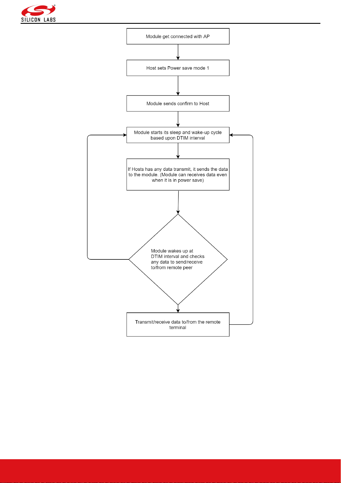
RS9116W Wi-Fi AT Command Programming Reference Manual
Version 2.0
silabs.com | Building a more connected world. 78 | Page
Figure 22: Power Save Mode 1
After having configured the module to power save mode, the Host can issue subsequent commands. In power save
mode 1 the module can receive data from host at any point of time, but it can send/receive the data to/from remote
terminal only when it is awake at DTIM intervals.
5.16.3 Power Save Mode 2
Once the module is configured to power save mode 2, it can be woken up either by the Host or periodically during its
sleep-wake up cycle based upon the DTIM interval.
Power mode 2 is GPIO based. In ULP mode, feature_bit_map[4]has to be set in opermode command. In this mode,
Whenever host want to send data to module, gives wakeup indication to module by setting ULP_GPIO_5 high in case
of LP or UULP_GPIO_2 in case of ULP(which make module to wake up from power save). After wakeup, if the
module is ready for data transfer, it sends wakeup indication to host. Host required to wait until module give wakeup
indication before sending any data to module.
After completion of data transfer host can give sleep permission to module by resetting ULP_GPIO_5 in case of LP or
Page 79
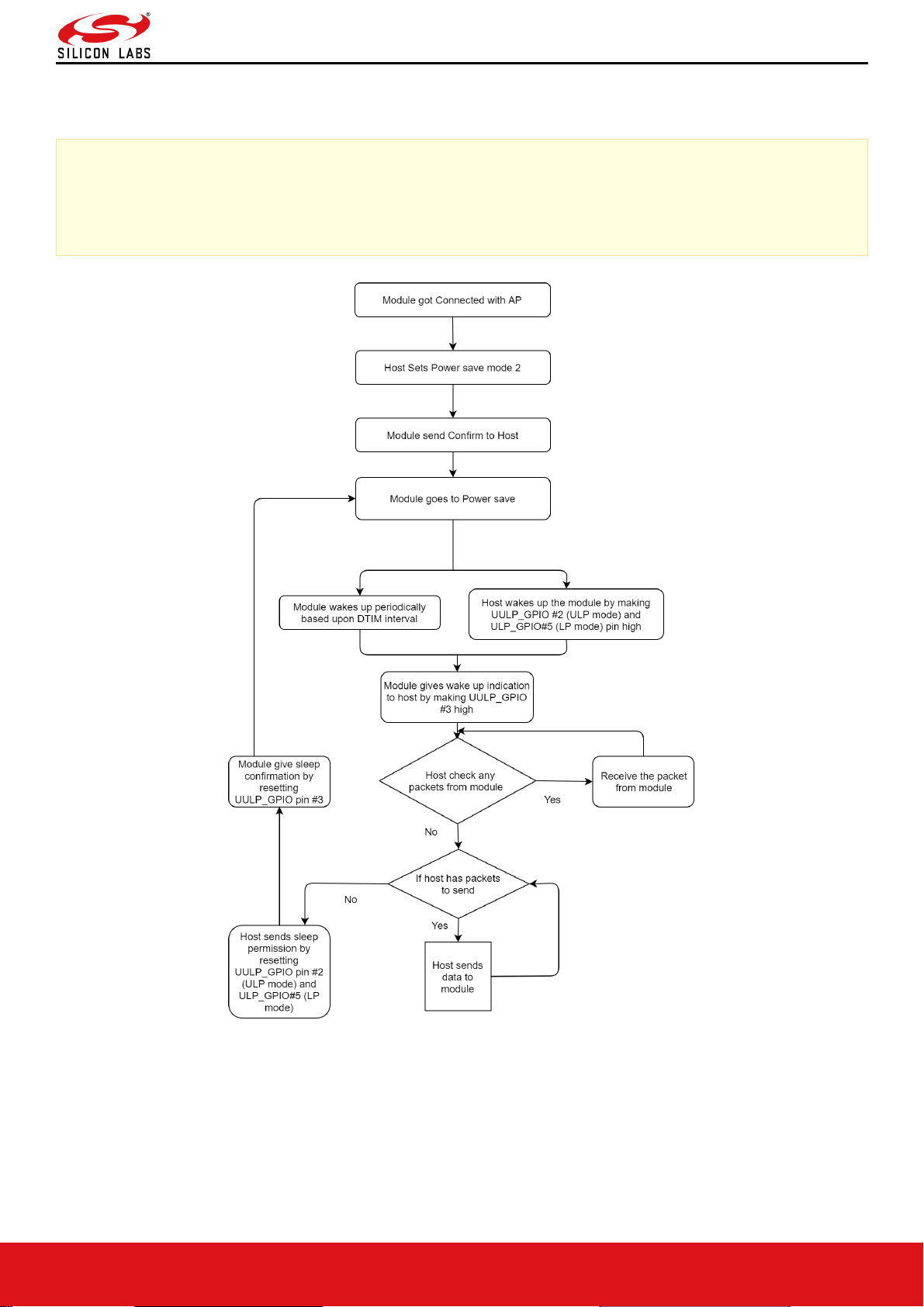
RS9116W Wi-Fi AT Command Programming Reference Manual
Version 2.0
silabs.com | Building a more connected world. 79 | Page
UULP_GPIO_2 in case of ULP. After recognizing sleep permission from host, module give confirmation to host by
resetting UULP_GPIO_3 and again gets back to its sleep-wakeup cycle.
Module can send received packets or responses to host at any instant of time. No handshake is required on Rx path.
Note:
1. Bydefault UULP_GPIO_3 is used for wakeup indication to host.
2. If BIT(0) is set in config_feature_bit_map then UULP_GPIO_0 is used for wakeup indication to host.
Figure 23: Power Save Mode 2
5.16.4 Power Save Mode 3
Power Mode 3 is message based power save. In Power Mode 3 like Power mode 2 both radio and SOC of RS9116WiSeConnect are in power save mode. This mode is significant when module is in associated state with AP. Module
wakes up periodically upon every DTIM and gives wakeup message ("WKP") to host. Module cannot be woken up
asynchronously. Every time module intends to go to sleep it sends a sleep request message ("SLP") to the host and
expects host to send the ack message. Host either send ack ("ACK") or any other pending message. But once ack is
sent, Host should not send any other message unless next wakeup message from module is received.
Page 80
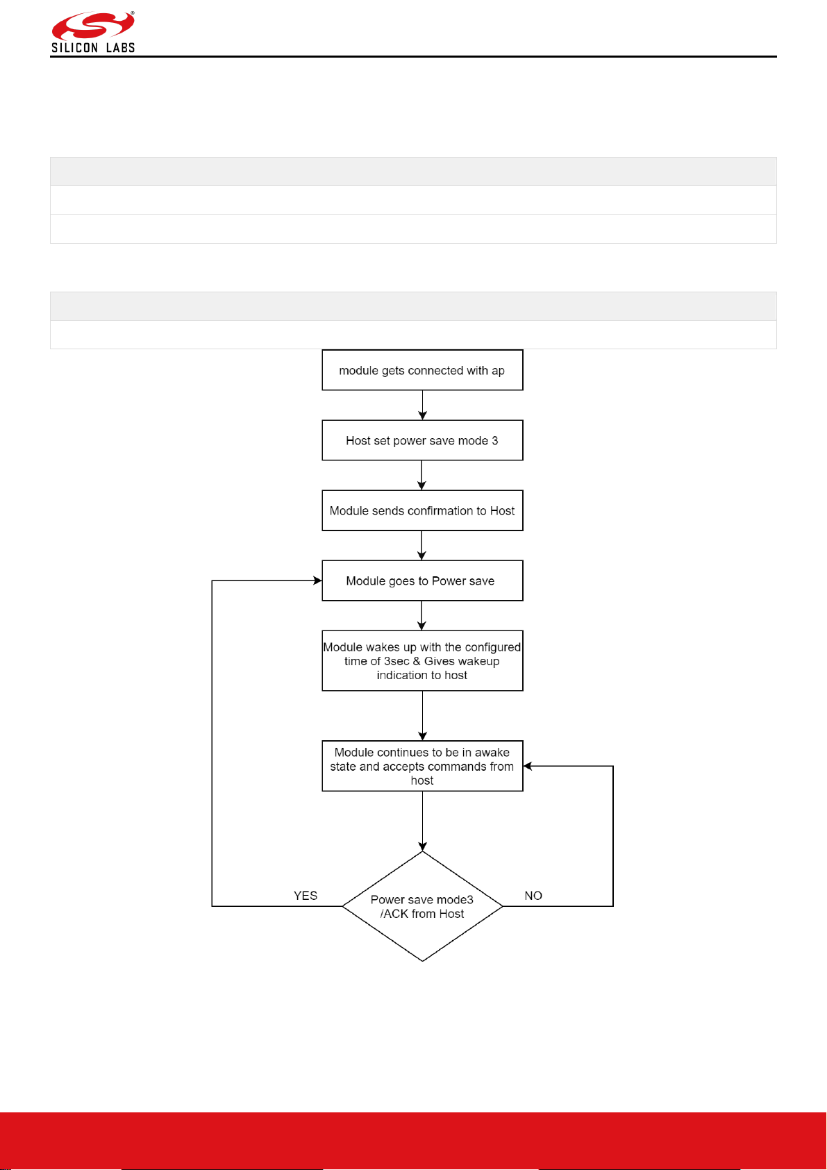
RS9116W Wi-Fi AT Command Programming Reference Manual
Version 2.0
silabs.com | Building a more connected world. 80 | Page
Module shall not go into complete power-save state if ack is not received from host for given sleep message. Module
can send received packets or responses to host at any instant of time. No handshake is required on Rx path.
Table 10: Message from Module in Power Save Mode
AT Mode
"WKP"
"SLP"
Table 11: Message from host in Power Save Mode
AT Mode
"ACK"
Figure 24: Power Save Mode 3
5.16.5 Power Save Mode 8
This command must be issued after Init command.
In Power Mode 8 both RF and SOC of RS9116-WiSeConnect are in complete power save mode. This mode is
significant when module is not connected with any AP. Power mode 8 is GPIO based. In ULP mode ,
Page 81
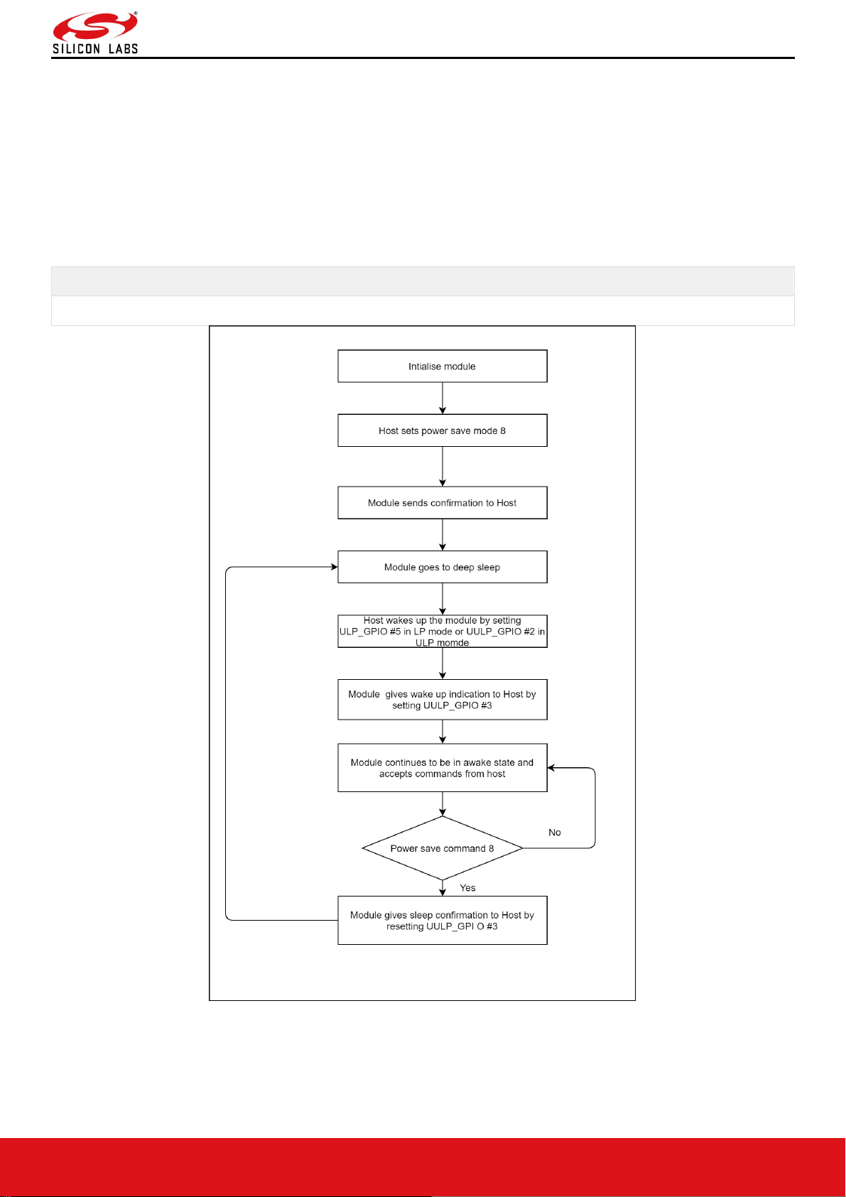
RS9116W Wi-Fi AT Command Programming Reference Manual
Version 2.0
silabs.com | Building a more connected world. 81 | Page
feature_bit_map[4]has to be set in opermode command.
In case of LP (when ulp_mode_enable is '0') host can wakeup the module from power save by making ULP_GPIO_5
high.
In case of ULP (when ulp_mode_enable is '1' or '2') host can wakeup the module from power save by making
UULP_GPIO_2 high.
When ulp_mode_enable is set to '0' or '1', once the module gets wakeup it continues to be in wakeup state until it gets
power mode 8 commands from host.
When ulp_mode_enable is set to '2', after waking up from sleep module sends following message to host when RAM
retention is not enabled. After receiving this message host needs to start giving commands from beginning(opemode)
as module's state is not retained.
Table 12: Message from Module in ULP Mode 2
AT Mode
"WKP FRM SLEEP"
Figure 25: Power Save Mode 8
5.16.6 Power Save Mode 9
In Power Mode 9 both Radio and SOC of RS9116-WiSeConnect are in complete power save mode. This mode is
significant when module is not connected with any AP. Once power mode 9 command is given, the module goes to
sleep immediately and wakes up after sleep duration configurable by host by set sleep timer command. If host does
Page 82
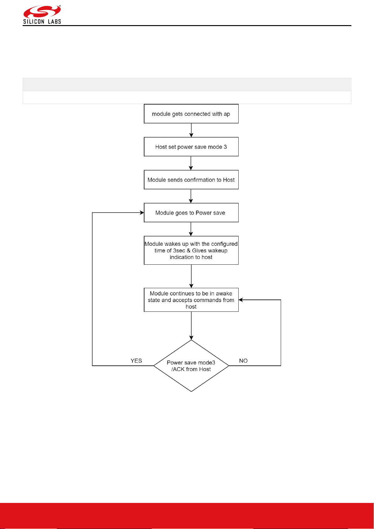
RS9116W Wi-Fi AT Command Programming Reference Manual
Version 2.0
silabs.com | Building a more connected world. 82 | Page
not set any default time, then the module wakes up in 3sec by default. Upon wakeup module sends a wakeup
message to the host and expects host to give ack before it goes into next sleep cycle. Host either send ack or any
other messages but once ACK is sent no other packet should be sent before receiving next wakeup message.
When ulp_mode_enable is set to '2', after waking up from sleep, the module sends following message to host when
RAM retention is not enabled. After receiving this message, host needs to start giving commands from beginning
(opemode) as module's state is not retained.
AT Mode
"WKP FRM SLEEP"
Figure 26: Power Save Mode 9
5.17 PSK/PMK
Description:
The command is used to set the PSK (Pre shared key) to join to WPA/WPA2-PSK enabled APs. Using this command
user can also pass the PMK (PAIRWISE MASTER KEY) as a parameter and can also generate PMK by providing
PSK and SSID of connecting AP.
User can directly give PMK from host to reduce the connection time. This command should be issued after init and
before join command, if module needs to connect to an secure Access point. This command can be ignored if the AP
is in Open mode.
Command Format:
Page 83

RS9116W Wi-Fi AT Command Programming Reference Manual
Version 2.0
silabs.com | Building a more connected world. 83 | Page
AT Mode:
at+rsi_psk=<TYPE>,<psk_or_pmk >,<ap_ssid >\r\n
Command Parameters:
TYPE[1 byte]: possible values of this field are 1, 2, 3.
1 - indicate pre_shared_key is provided in psk_or_pmk field,
2 - indicate pairwise_master_key is provided in psk_or_pmk field,
3 - indicate generate pairwise master key from given pre shared key and SSID to which module wants to connect.
Note:
AT command mode TYPE 4 and 5 is added to support ‘,’ in PSK.
TYPE 4 – indicate length based PSK
TYPE 5 – indicate generation of PMK from length based PSK and SSID
To support above type new parameter introduced in the command and command format
for the same is
at+rsi_psk=<TYPE>,<length_of_psk>,<psk_or_pmk >,<ap_ssid >\r\n
where,
length_of_psk (1 byte): gives the length of psk which can includes ‘,’ for example at+rsi_psk=4,10,123,456789
Where,
“123,456789” is psk with 10 bytes length
psk_or_pmk[64 bytes]: In this field expected parameters are pre shared key of the access point to which module
wants to associate or pair wise master key. Length of this field is 64 Bytes. In case of PMK only 32 bytes are valid, In
case of PSK length can vary (8 to 63).
Note:
PMK is of 32 Bytes. In AT plus command mode, 32 bytes of PMK is given in hex format (64 characters) in the
command.
For Example: If PMK is of array, PMK[32] = {0x71, 0x72, 0x01, 0x0A, 0x16, 0x17, 0x07,0x90, 0x71, 0x72, 0x01,
0x0A, 0x16, 0x17, 0x07,0x90, 0x71, 0x72, 0x01, 0x0A, 0x16, 0x17, 0x07,0x90, 0x71, 0x72, 0x01, 0x0A, 0x16,
0x17, 0x07,0x90};, then the command should be given as
at+rsi_psk=2,7172010A161707907172010A161707907172010A161707907172010A16170790\r\n
ap_ssid[32 bytes]: This field contains the SSID of the access point, this field will be valid only if TYPE value is 3.
Note:
If user generates PMK using TYPE 3 (i.e. by providing psk and ssid) then module uses generated PMK for
connection establishment and there is no need to give pre shared key or pair wise master key again.
Response:
Response contains following payload only if TYPE value is 3. In case of TYPE 1 & 2 response does not contain any
payload.
AT Mode:
Result Code
Description
OK
Successful execution of the command. If TYPE value is '1'or '2'.
OK< pmk >
Successful execution of the command. If TYPE value is '3'.
ERROR<Error code>
Failure
Page 84

RS9116W Wi-Fi AT Command Programming Reference Manual
Version 2.0
silabs.com | Building a more connected world. 84 | Page
Response Parameters:
Pair wise master key of 32 bytes is given to host if TYPE is 3.
Relevance:
This command is relevant in operating mode 0.
Possible Error Codes:
Possible error codes for this command are 0x0021, 0x0025,0x0026,0x0028,0x002C,0x0039, 0x003a, 0x003b .
Example:
AT Mode:
To join a WPA2-PSK security enabled network with key "12345ABCDE", the command is
at+rsi_psk=1,12345ABCDE\r\n
0x61 0x740x2B0x720x730x690x5F 0x70 0x73 0x6B 0x3D 0x31 0x2c 0x31 0x32 0x33 0x34 0x35 0x41 0x42 0x43
0x44 0x45 0x0D 0x0A
Response:
OK\r\n
0x4F 0x4B 0x0D 0x0A
To join a WPA2-PSK security enable network with pairwise_master_key
"ABCDEFABCDEFABCDEF12345678901234ABCDEFABCDEFABCDEF12345678901234" ,the command is
at+rsi_psk=2, ABCDEFABCDEFABCDEF12345678901234ABCDEFABCDEFABCDEF12345678901234,\r\n
Response:
OK\r\n
0x4F 0x4B 0x0D 0x0A
To generate pairwise_master_key for the pre_shared_key "12345678" and SSID "wise_ap", the command is
at+rsi_psk=3,12345678,wise_ap\r\n
Response:
OK<pairwise_master_key>\r\n
0x4F 0x4B <32bytes of pairwise_master_key> 0x0D 0x0A
5.18 Set WEP Keys
Description:
This command configures the WEP key in the module to connect to an AP with WEP security. This command should
be issued before join.
Command Format:
AT Mode:
at+rsi_wepkey=< index >,< key1 >,< key2 >,< key3 >,< key4 >\r\n
Command Parameters:
index[2 bytes]: used to select key index configured in AP
0-Key 1 will be used.
1-Key 2 will be used.
2-Key 3 will be used.
3-Key 4 will be used.
Key/Key1/Key2/Key3/Key4: Actual keys. The module supports WEP hex mode only.
The key to be supplied to the AP should be of 10 characters (for 64 bit WEP mode) or 26 characters (for 128 bit WEP
mode), and only the following characters are allowed for the key: A,B,C,D,E,F,a,b,c,d,e,f,0,1,2,3,4,5,6,7,8,9
Response:
AT Mode:
Result Code
Description
OK
Successful execution of the command
ERROR<Error code>
Failure
Possible error codes:
Possible error codes are 0x0021, 0x0025, 0x002C,0x002D
Page 85

RS9116W Wi-Fi AT Command Programming Reference Manual
Version 2.0
silabs.com | Building a more connected world. 85 | Page
Relevance:
This command is relevant when the module is configured in Operating Mode 0.
Example:
AT Mode:
Give write up for the below key entry
at+rsi_wepkey=0,ABCDE12345,ABCDE12346,ABCDE12347, ABCDE12348\r\n
If the user wants to enter only one valid key
at+rsi_wepkey=0,ABCDE12345,0,0,0\r\n
If the user wants to enter only one valid key
at+rsi_wepkey=2,0,0,ABCDE12345,0\r\n
Response:
OK\r\n
0x4F 0x4B 0x0D 0x0A
5.19 Set WEP Authentication Mode
Description:
This command configures the authentication mode for WEP in the module, if the AP is in WEP security mode. This
command is supported only in AT Mode.
Command Format:
at+rsi_authmode=auth_mode\r\n
Command Parameters:
auth_mode: set to '0' for open WEP authentication
Note:
WEP shared mode is not supported in RS9116_WC_GENR_0_x_x release.
Response:
Result Code
Description
OK
Successful execution of the command
ERROR<Error code>
Failure,
Possible error codes are 0x0021, 0x0025, 0x002C, 0xFFF8,0x002D
Relevance:
This command is relevant when the module is configured in Operating Mode 0
Example:
at+rsi_authmode=0\r\n
0x61 0x74 0x2B0x72 0x73 0x69 0x5F 0x61 0x75 0x74 0x68 0x6D 0x6F 0x64 0x65 0x3D 0x30 0x0D 0x0A
Response:
OK\r\n
0x4F 0x4B 0x0D 0x0A
5.20 Set EAP Configuration
Description:
This command is used to configure the EAP parameters for connecting to an Enterprise Security enabled Access
Point. The supported EAP types are EAP-TLS, EAP-TTLS, EAP-PEAP,EAP-FAST and EAP-LEAP.
Note:
Page 86

RS9116W Wi-Fi AT Command Programming Reference Manual
Version 2.0
silabs.com | Building a more connected world. 86 | Page
EAP-GTC is not supported for EAP-FAST.
This command can be sent any time after at+rsi_init and before at+rsi_join in enterprise security mode.
Command Format:
AT Mode:
at+rsi_eap =< eapMethod >,< innerMethod >,< userIdentity >,< password >,< okc >,<private_key_password>\r\n
Command Parameters:
eapMethod[32 bytes]: Should be one of among TLS, TTLS, FAST, PEAP or LEAP. It should be ASCII character
string.
innerMethod[32 bytes]: This field is valid only in TTLS/PEAP. In case of TTLS/PEAP supported inner methods are
MSCHAP/MSCHAPV2. In case of TLS/FAST/LEAP this field is not valid, and it should be fixed to MSCHAPV2.
Here MSCHAP/MSCHAPV2 are ASCII character strings.
userIdentity[64 bytes]: User ID which is configured in the user configuration file of the radius sever.
Password[128 bytes]: Password which is configured in the user configuration file of the Radius Server for that User
Identity.
Okc[4 bytes]: To enable or disable opportunistic key caching(OKC)
0 – disable
1 – enable
When this is enabled, module will use cached PMKID to get MSK (Master Session Key) which is need for generating
PMK which is needed for 4-way handshake.
private_key_password[82 bytes]: This is password for encrypted private key given to the module. Module will use
this password during decryption of encrypted private key.
Password length should not be more than 80 bytes
Response:
AT Mode:
Result Code
Description
OK
Successful execution of the command
ERROR<Error code>
Failure,
Possible error codes:
Possible error codes are 0x0021, 0x0025, 0x002C.
Relevance:
This command is relevant when the module is configured in Operating Mode 2.
5.21 Set Certificate
Description:
This command is used to load/erase SSL (certificate and private keys) and enterprise security (EAP-TLS or EAPFAST) certificates. Certificates should be loaded before using SSL/EAP. This command should be sent before join
command for enterprise security mode and before socket creation for SSL sockets. Certificates will be loaded in nonvolatile memory of the module, so that loading certificate is required to be done only once.
Note:
This command should be sent only after opermode command.
Page 87

RS9116W Wi-Fi AT Command Programming Reference Manual
Version 2.0
silabs.com | Building a more connected world. 87 | Page
Command Format:
AT Mode:
at+rsi_cert =< CertType >,< total_len >,< KeyPwd >,< Certificate >\r\n
Command Parameters:
total_len[2 bytes]: Certificate's total length in bytes.
Note:
1. For Enterprise security, maximum cert_len should be less than 12280 bytes. For SSL Certificates, the max
length is 12280 bytes and for the Private Keys, it is 4088 bytes.
2. Module shares same SSL certificates for all supported SSL sockets.
3. For enterprise, user can load certificates in two ways
- User can provide wifiuser.pem which contains 4 certificates in a given fixed order of private key, client
certificate 1, client certificate 2, CA certificate with CertType as 1.
- User can load individual EAP certificates private key, public key, and CA certificates with CertType as
17,33 and 49 respectively. Maximum certificate length for each individual certificate is 4088 bytes
4. Certificate Loading into Flash is only allowed upto init state. After init state e.g. scan/join etc. certificate
loading into flash is not allowed.
5. Certificate Loading into RAM is allowed in connected state also provided same type of socket already does
not exist. For example, loading client cert is only allowed if there does not exist any client socket. Same is
for server certificates too
Note:
Recommended to use loading of single certificate method (wifiuser.pem)
Note:
By default, SSL certificates will be loaded onto flash. Set BIT(27) in tcp_ip_feature_bit_map to load SSl
certificate onto RAM.
cert_type[1 byte]
Type of certificate
1
EAP client certificate
2
FAST PAC file
3
SSL Client Certificate
4
SSL Client Private Key
5
SSL CA Certificate
6
SSL Server Certificate
7
SSL Server Private Key
17
EAP private key
33
EAP public key
49
EAP CA certificate
In case of AT mode Host need to send whole certificate at a time.
keyPwd(128 bytes): Reserved.
Page 88

RS9116W Wi-Fi AT Command Programming Reference Manual
Version 2.0
silabs.com | Building a more connected world. 88 | Page
certificate: This is the data of the actual certificate.
Certificate erase:
For erasing certificate,
total_len, KeyPwd, Certificate fields should be set to '0' in AT Mode.
cert_type should be set to type of the certificate to erase as mentioned above.
Response:
AT Mode:
Result Code
Description
OK
Successful execution of the command
ERROR<Error code>
Failure
Possible error codes:
Possible error codes are 0x0015,0x0021, 0x0025,0x0026, 0x002C.
Relevance:
This command is relevant when the module is configured in Operating Mode 0,2
Example:
AT Mode:
It may not be possible to issue this command in Hyper-terminal because the content of a certificate file needs to be
supplied as one of the inputs of the command. This can be done by other means, such as using a Python script. A
sample Python excerpt is shown below, where wifiuser.pem is the names of the certificate file:
def set_cert():
print "Set certificate\n"
f3 = open('e:\\certificates\wifiuser.pem', 'r+')
str = f3.read()
num =len (str)
print 'Certificate len', num
out='at+rsi_cert=1,6522,password,'str'\r\n'
print 'Given command'
sp.write(out)
For loading certificate:
at+rsi_cert=1,10,12345678,@$cd5%ghij\r\n
0x61 0x74 0x2B 0x72 0x73 0x69 0x5F 0x63 0x65 0x72 0x74 0x3D 0x31 0x2C 0x31 0x30 0x2C 0x31 0x32 0x33 0x34
0x35 0x36 0x37 0x38 0x2C 0x40 0x24 0x63 0x64 0x35 0x25 0x67 0x68 0x69 0x6A 0x0D 0x0A
Response:
OK\r\n
0x4F 0x4B 0x0D 0x0A
For erasing certificate:
at+rsi_cert=1,0,0,0\r\n
0x61 0x74 0x2B 0x72 0x73 0x69 0x5F 0x63 0x65 0x72 0x74 0x3D 0x31 0x2C 0x30 0x2C 0x30 0x2C 0x30 0x0D 0x0A
Response:
OK\r\n
0x4F 0x4B 0x0D 0x0A
5.22 Set Certificate with Indices
Description:
This command is used to load/erase SSL (certificate and private keys) and enterprise security (EAP-TLS or EAPFAST) certificates. Certificates should be loaded before using SSL/EAP. This command should be sent before join
command for enterprise security mode and before socket creation for SSL sockets. Certificates will be loaded in nonvolatile memory of the module, so that loading certificate is required to be done only once.
Page 89

RS9116W Wi-Fi AT Command Programming Reference Manual
Version 2.0
silabs.com | Building a more connected world. 89 | Page
Note:
This command is used for WI-FI alone mode in case of loading 3 SSL certificates to FLASH.
Note:
This command should be sent only after opermode command.
Command Format:
AT Mode:
at+rsi_cert =< CertType >,< total_len >,<CertInx>,< KeyPwd >,< Certificate >\r\n
Command Parameters:
total_len[2 bytes]: Certificate's total length in bytes.
Note:
1. For Enterprise security, maximum cert_len should be less than 12280 bytes. For SSL Certificates, the max
length is 12280 bytes and for the Private Keys, it is 4088 bytes.
2. Module shares same SSL certificates for all supported SSL sockets.
3. For enterprise, user can load certificates in two ways
- User can provide wifiuser.pem which contains 4 certificates in a given fixed order of private key, client
certificate 1, client certificate 2, CA certificate with CertType as 1.
- User can load individual EAP certificates private key, public key, and CA certificates with CertType as 17,33
and 49 respectively. Maximum certificate length for each individual certificate is 4088 bytes.
4. Certificate Loading into Flash is only allowed upto init state. After init state e.g. scan/join etc certificate loading
into flash is not allowed.
5. Certificate Loading into RAM is allowed in connected state also provided same type of socket already does
not exist. For example, loading client cert is only allowed if there does not exist any client socket. Same is for
server certificates too.
Note:
Recommended to use loading of single certificate method (wifiuser.pem)
Note:
1. Set BIT(27 ) in tcp_ip_feature_bit_map to load SSl certificate onto RAM. By default, SSL certificates will be
loaded onto flash.
2. Set BIT(31) in tcp_ip_feature_bit_map & BIT(29) in ext_tcp_ip_feature_bit_map to open 3 SSL Client sockets.
cert_type[1 byte]
Type of certificate
1
EAP Client certificate
2
FAST PAC file
3
SSL Client Certificate
Page 90

RS9116W Wi-Fi AT Command Programming Reference Manual
Version 2.0
silabs.com | Building a more connected world. 90 | Page
cert_type[1 byte]
Type of certificate
4
SSL Client Private Key
5
SSL CA Certificate
6
SSL Server Certificate
7
SSL Server Private Key
17
EAP private key
33
EAP public key
49
EAP CA certificate
In case of AT mode Host need to send whole certificate at a time.
CertInx (1 byte): 1. Module can hold two sets of SSL certificate into RAM. This field is used to provide the index of
the certificates and possible values are 0 and 1.
2. Module can hold three sets of SSL certificate onto Flash. This field is used to provide the index of the certificates
and possible values are 0, 1 and 2.
Note:
Currently RS9116 can either load certificates onto RAM or FLASH, but not both at a time.
keyPwd(127 bytes): Reserved.
certificate: This is the data of the actual certificate.
Certificate erase:
For erasing certificate,
total_len, KeyPwd , Certificate fields should be set to '0' in AT Mode.
cert_type should be set to type of the certificate to erase as mentioned above
Response:
AT Mode:
Result Code
Description
OK
Successful execution of the command
ERROR<Error code>
Failure
Possible error codes:
Possible error codes are 0x0015,0x0021, 0x0025,0x0026, 0x002C, 0x005D, 0x005E, 0x005F.
Relevance:
This command is relevant when the module is configured in Operating Mode 0, 2.
Example:
AT Mode:
It may not be possible to issue this command in Hyper-terminal, because the content of a certificate file needs to be
supplied as one of the inputs of the command. This can be done by other means, such as using a Python script. A
sample Python excerpt is shown below, where wifiuser.pem is the name of the certificate file to load certificate with
index 0:
def set_cert():
print "Set certificate\n"
f3 = open('e:\\certificates\wifiuser.pem', 'r+')
str = f3.read()
num =len (str)
print 'Certificate len', num
out='at+rsi_cert_inx=1,6522,0,password,'str'\r\n'
Page 91

RS9116W Wi-Fi AT Command Programming Reference Manual
Version 2.0
silabs.com | Building a more connected world. 91 | Page
print 'Given command'
sp.write(out)
For loading certificate with index 0:
at+rsi_cert_inx=1,10,0,12345678,@$cd5%ghij\r\n
0x61 0x74 0x2B 0x72 0x73 0x69 0x5F 0x63 0x65 0x72 0x74 0x5F 0x69 0x6E 0x78 0x3D 0x31 0x2C 0x31 0x30 0x2C
0x30 0x2C 0x31 0x32 0x33 0x34 0x35 0x36 0x37 0x38 0x2C 0x40 0x24 0x63 0x64 0x35 0x25 0x67 0x68 0x69 0x6A
0x0D 0x0A
Response:
OK\r\n
0x4F 0x4B 0x0D 0x0A
For erasing certificate with index 0:
at+rsi_cert_inx=1,0,0,0,0\r\n
0x61 0x74 0x2B 0x72 0x73 0x69 0x5F 0x63 0x65 0x72 0x74 x5F 0x69 0x6E 0x78 0x3D 0x31 0x2C 0x30 0x2C 0x30
0x2C 0x30 0x2C 0x30 0x0D 0x0A
Response:
OK\r\n
0x4F 0x4B 0x0D 0x0A
5.23 Disassociate
Description:
This command is issued to request the module to disassociate (disconnect) from an Access Point. The Host can then
issue a fresh set of Init, Scan and Join commands to connect to a different Access Point or the same Access Point
with a different set of connection parameters. This command can also be used to stop the module from continuing an
on-going rejoin operation. Additionally, this command is used when the module is in AP mode, to remove clients from
its list of connected nodes.
Command Format:
AT Mode:
at+rsi_disassoc=< mode_flag >,< client_mac_addr >\r\n
Command Parameters:
mode_flag[2 bytes]:
Mode
Functionality
0
Module is in client mode. The second parameter mac_addr is ignored when mode is 0.
1
Module is in AP mode.
client_mac_addr[6 bytes]: MAC address of the client to disconnect. Used when the module is in AP mode
Response:
AT Mode:
Result Code
Description
OK
Successful execution of the command
ERROR<Error code>
Failure
Possible error codes:
Possible error codes are 0x0006, 0x0013, 0x0021, 0x002C, 0x0015.
Relevance:
This command is relevant when the module is configured in Operating Mode 0, 1, 2 and 6.
Note:
After issuing disconnect command, any power save enabled by that time will be disabled. User can reissue the
power save command after initializing the module again.
Page 92

RS9116W Wi-Fi AT Command Programming Reference Manual
Version 2.0
silabs.com | Building a more connected world. 92 | Page
Example:
AT Mode:
Module is in client mode and is connected to an AP. It wants to formally disconnect from the AP.
at+rsi_disassoc=0\r\n
0x61 0x74 0x2B 0x72 0x73 0x69 0x5F 0x64 0x69 0x73 0x61 0x73 0x73 0x6F 0x63 0x3D 0x30 0x0D 0x0A
Module is in AP mode and 3 clients are connected to it. One of the clients, with MAC 0x01 0x02 0x03 0x040 0x05
0x06 , needs to be disconnected by the AP.
at+rsi_disassoc=1,010203040506\r\n
0x61 0x740x2B0x720x730x690x5F 0x64 0x69 0x73 0x61 0x73 0x73 0x6F 0x63 0x3D 0x31 0x2C 0x30 0x31 0x30
0x32 0x30 0x33 0x30 0x34 0x30 0x35 0x30 0x36 0x0D 0x0A
Response:
OK\r\n
0x4F 0x4B 0x0D 0x0A
5.24 Set IP Parameters
Description:
This command configures the IP address, subnet mask and default gateway for the module.
Command Format:
AT Mode:
at+rsi_ipconf=< dhcpMode >, < ipaddr >,< netmask >,< gateway >, < hostname >, <vap id>,< fqdnFlag>\r\n
Command Parameters:
dhcpMode[1 byte]: Used to configure TCP/IP stack in manual or DHCP modes.
0– Manual
1– DHCP enabled
3 - To enable DHCP and to send host name in DHCP discover
5 - To enable Option 71 with static IP
Note:
In AP mode only DHCP manual mode (static IP) is valid. sending host name is valid only in DHCP enable
mode.
4 -To enable FQDN Option with static ip (Option 81 with static IP)
7 -To enable DHCP, hostname, DHCP Client FQDN option (Option 81 with Dynamic IP)
9 - To support DHCP unicast Offer from server
ipAddr[4 bytes]: IP address in 4 bytes hex format. This can be 0's in the case of DHCP.
netmask[4 bytes]: Subnet mask in 4 bytes hex format. This can be 0's in the case of DHCP.
Gateway[4 bytes]: Gateway in 4 bytes hex format. This can be 0's in the case of DHCP.
hostname[31 bytes]: Host name for DHCP Client. This can be null, when DHCP mode is not enabled. This field is
valid only when dhcpMode value is 3. Maximum Hostname length is valid up to 31 bytes including NULL.
Vap_id[1 byte]: Possible values are 0 and 1.
When 1 - Used start DHCP server in concurrent AP mode (should be given before AP creation i.e. join).
When 0 – Used to assign static IP for client mode.
Note:
vap_id will be considered only in concurrent mode and when dhcp mode is manual.
Page 93

RS9116W Wi-Fi AT Command Programming Reference Manual
Version 2.0
silabs.com | Building a more connected world. 93 | Page
fqdnFlag[4 b ytes]:
0 - DNS Client should update TYPE_A(host name) record and TYPE_PTR records.
1 - DHCP Server will update both TYPE_A and TYPE_PTR records
Response:
AT Mode:
Result Code
Description
OK< macAddr >< ipaddr >< netmask >< gateway >
Successful execution of the command
ERROR<Error code>
Failure
Response Parameters:
macAddr(6 bytes): MAC Address
ipAddr(4 bytes) : Assigned IP address
netmask(4 bytes): Assigned subnet address
gateway(4 bytes): Assigned gateway address
Possible error codes:
Possible error codes are 0x0021, 0x0025, 0x002C, 0xFFFC,0xFF74, 0xFF9C, 0xFF9D.
Relevance:
This command is relevant when the module is configured in Operating Mode 0, 1, 2 and 6.
Example:
AT Mode:
To configure in manual mode, with 192.168.1.3, 255.255.255.0 and 192.168.1.1 as the IP address, subnet mask and
gateway the command is
at+rsi_ipconf=0,192.168.1.3,255.255.255.0,192.168.1.1\r\n
0x610x740x2B0x720x730x690x5F0x690x700x63
0x6F0x6E0x660x3D 0x300x2C0x310x390x320x2E
0x310x360x380x2E0x310x2E0x330x2C 0x320x35
0x350x2E0x320x350x350x2E0x320x350x350x2E
0x300x2C 0x310x390x320x2E0x310x360x380x2E
0x310x2E0x310x0D 0x0A
Response:
OK<MAC_Address><IP_Address><Subnet_Mask><Gateway>\r\n
0x4F 0x4B 0x01 0x02 0x03 0x04 0x05 0x06 0xC0 0xA8 0x01 0x03 0xFF 0xFF 0xFF 0x00 0xC0 0xA8 0x01 0x01
0x0D0x0A
To configure the IP in DHCP enabled mode, the command is
at+rsi_ipconf=1,0,0,0\r\n
0x61 0x74 0x2B 0x72 0x73 0x69 0x5F 0x69 0x70 0x63 0x6F 0x6E 0x66 0x3D 0x31 0x2C 0x30 0x2C 0x30 0x2C 0x30
0x0D 0x0A
Response:
OK<MAC_Address><IP_Address><Subnet_Mask><Gateway>\r\n
0x4F 0x4B 0x01 0x02 0x03 0x04 0x05 0x06 0xC0 0xA8 0x01 0x03 0xFF0xFF0xFF0x000xC00xA80x01 0x01 0x0D
0x0A
To configure the IP in DHCP enabled mode with hostname, the command is
at+rsi_ipconf=3,dhcp_client\r\n
0x61 0x74 0x2B 0x72 0x73 0x69 0x5F 0x69 0x70 0x63 0x6F 0x6E 0x66 0x3D 0x31 0x2C 0x30 0x2C 0x30 0x2C 0x30
0x0D 0x0A
Response:
OK<MAC_Address><IP_Address><Subnet_Mask><Gateway>\r\n
0x4F 0x4B 0x01 0x02 0x03 0x04 0x05 0x06 0xC0 0xA8 0x01 0x03 0xFF0xFF0xFF0x000xC00xA80x01 0x01 0x0D
0x0A
5.25 IP Change Notification
Description:
This notification is received when module gets a different IP compared to modules old IP address, after DHCP
renewal. Module indicates this IP change to host by an asynchronous frame.
Page 94

RS9116W Wi-Fi AT Command Programming Reference Manual
Version 2.0
silabs.com | Building a more connected world. 94 | Page
Command Format:
N/A
Command Parameters:
N/A
Response:
AT Mode:
Result Code
Description
AT+RSI_IPCONF< macAddr >< ipaddr >< netmask >< gateway >
Response Parameters:
macAddr(6 bytes): MAC Address
ipAddr(4 bytes): Assigned IP address
netmask(4 bytes): Assigned subnet address
gateway(4 bytes): Assigned gateway address
Relevance:
This command is relevant when the module is configured in Operating Mode 0, 1, 2 and 6.
Example:
AT Mode:
AT+RSI_IPCONF< macAddr >< ipaddr >< netmask >< gateway >\r\n
0x41 0x54 0x2B 0x52 0x53 0x49 0x5F 0x49 0x50 0x43 0x4F 0x4E 0x46 0x3D 0x01 0x02 0x03 0x04 0x05 0x06 0xC0
0xA8 0x01 0x03 0xFF0xFF0xFF0x000xC00xA8
0x01 0x01 0x0D 0x0A
5.26 Set IPv6 Parameters
Description:
This command configures the IPv6 address, prefix length and default router for the module.
Command Format:
AT Mode:
at+rsi_ipconf6=< mode >,< prefixLength >,< ipaddr6 >, < gateway6 >\r\n
Command Parameters:
mode[2 bytes]:
Used to configure TCP/IP stack in manual or DHCPv6 modes.
0–Manual
1–DHCPv6
prefixLength[2 bytes]: Prefix length of the IPv6 address.
ipaddr6[16 bytes]: IPv6 address. This can be 0's in the case of DHCPv6.
gateway6[16 bytes]: Default router's IPv6 address. This should be Null in the case of DHCPv6.
IPV6 address is generally of the form - octet of four hexadecimal digits separated by "colons".
e.g. 2001:0db8:1:0:0:0:0:123 (supported format)
2001:db8:1::123 (not supported format)
Double colons are used in place of continuous zeroes in IPV6 address, to minimize the IPV6 address, but in RS9116WiSeConnect double colons are not supported. In ipconf6 command you have to supply all the eight groups of four
hexadecimal digits.
Response:
AT Mode:
Result Code
Description
OK< prefixLength >< ipaddr6>< defaultgw6>
Successful execution of the command.
ERROR<Error code>
Failure
Page 95

RS9116W Wi-Fi AT Command Programming Reference Manual
Version 2.0
silabs.com | Building a more connected world. 95 | Page
Response Parameters:
prefixLength(2 bytes): Prefix length of IPv6 address
ipaddr6(16 bytes): Assigned IPv6 address
defaultgw6(16 bytes): Assigned default_router address
Possible error codes:
Possible error codes are 0x0021, 0x0025, 0x002C, 0xFFFC, 0xFF9C,0xFF74, 0xFF9D.
Relevance:
This command is relevant when the module is configured in Operating Mode 0, 1, 2 and 6.
Example:
AT Mode:
To configure in manual mode, with 2001:db8:1:0:0:0:0:123 as the IPV6 address and with 2001:db8:1:0:0:0:0:100 as
router IPV6 address, the command is :
at+rsi_ipconf6=0,64,2001:DB8:1:0:0:0:0:123,2001:DB8:1:0:0:0:0:100\r\n
0x610x740x2B0x720x730x690x5F0x690x700x63 0x6F0x6E0x660x36 0x3D 0x300x2C0x360x340x32 0x300x30 0x31
0x3A0x440x420x380x3A0x310x3A 0x30 0x3A 0x30 0x3A 0x30 0x3A 0x30 0x3A 0x31 0x32 0x330x2C0x32 0x300x30
0x31 0x3A0x440x420x38 0x3A0x310x3A 0x30 0x3A 0x30 0x3A 0x30 0x3A 0x30 0x3A 0x31 0x00 0x000x0D 0x0A
Response:
OK< prefixLength >< ipaddr6 >< gateway6>\r\n
0x4F 0x4B 0x40 0x00 0xB8 0x0D 0x01 0x20 0x00 0x00 0x01 0x00 0x00 0x00 0x00 0x00 0x23 0x01 0x00 0x00 0xB8
0x0D 0x01 0x20 0x00 0x00 0x01 0x00 0x00 0x00 0x00 0x00 0x00 0x01 0x00 0x00 0x0D 0x0A
To configure the IPV6 in DHCPV6 enabled mode, the command is
at+rsi_ipconf6=1\r\n
0x61 0x74 0x2B 0x72 0x73 0x69 0x5F 0x69 0x70 0x63 0x6F 0x6E 0x66 0x36 0x3D 0x31 0x0D 0x0A
Response:
OK< prefixLength >< ipaddr6 >< gateway6>\r\n
0x4F 0x4B 0x40 0x00 0xB8 0x0D 0x01 0x20 0x00 0x00 0x01 0x00 0x00 0x00 0x00 0x00 0x36 0x01 0x00 0x00 0xB8
0x0D 0x01 0x20 0x00 0x00 0x01 0x00 0x00 0x00 0x00 0x00 0x00 0x01 0x00 0x00 0x0D 0x0A
The IPv6 address assigned to module by DHCPv6 server is 2001:DB8:1:0:0:0:0:136, default prefix 64 is used and
router ipv6 address is 2001:DB8:1:0:0:0:0:100.
5.27 SNMP
Description:
This command configures the SNMP agent in the module. This command can be issued only after set IP parameters
or set IPv6 parameters command. This is the first command for using SNMP feature
Command Format:
AT Mode:
at+rsi_snmp_enable=< snmpEnable >\r\n
Command Parameters:
snmpEnable[1 byte]:
To enable SNMP agent in module
0 - SNMP disable
1 - SNMP enable
Response:
AT Mode:
Result Code
Description
OK
Successful execution of the command.
ERROR<Error code>
Failure
Response Parameters:
N/A
Possible error codes:
Possible error codes are 0x0021, 0x0025, 0x002C,0xFF74,0x0015,0x100,0xFF82.
Page 96

RS9116W Wi-Fi AT Command Programming Reference Manual
Version 2.0
silabs.com | Building a more connected world. 96 | Page
Relevance:
This command is relevant when the module is configured in Operating Mode 0, 1, 2 and 6.
Example:
AT Mode:
To enable SNMP in module the command is
at+rsi_snmp_enable=1\r\n
0x610x740x2B0x720x730x690x5F0x73 0x6E 0x6D 0x70 0x5F 0x65 0x6E 0x61 0x62 0x6C 0x65 0x3D 0x31 0x0D
0x0A
Response:
OK\r\n
0x4F 0x4B 0x0D 0x0A
5.28 SNMP Set
Description:
This is an asynchronous message which module gives to host whenever it receives snmp set message from the
remote SNMP server, to set the value corresponding to the object id. This message can only be received when
module is configured as an SNMP agent.
Command Format:
AT Mode:
N/A
Command Parameters:
N/A
Response:
AT Mode:
Result Code
Description
AT_RSI_SNMP_SET=< object_id >,< length >,<
value >
Asynchronous message sent by remote snmp server and received
by the module.
Response Parameters:
object_id (128 bytes): object id for which the snmp server wants to set.
length (4bytes): length of value of object id.
LSB is returned first.
value (200bytes): value of object id to be set. Out of these 200 bytes, user has to consider only length number of
bytes.
Note:
Value contains maximum of 144 bytes in case of IPV6.
Possible error codes:
N/A
Relevance:
This message is relevant when the module is configured in Operating Mode 0, 1, 2 and 6.
Example:
AT Mode:
AT+RSI_SNMP_SET=1.3.6.1.2.1.1.1.0,4,home\r\n
0x41 0x54 0x2B 0x52 0x53 0x49 0x5F 0x53 0x4E 0x4D 0x50 0x5F 0x53 0x45 0x54 0x3D 0x31 0x2E 0x33 0x2E 0x36
0x2E 0x31 0x2E 0x32 0x2E 0x31 0x2E 0X31 0x2E 0x31 0x2E 0x30 0X00 0X00 0X00 0X00 0X00 0X00 0X00 0X00
0X00 0X00 0X00 0X00 0X00 0X00 0X00 0x2C 0x00 0x00 0x00 0x04 0x2C 0X68 0X6F 0X6D 0X65 0X00 0X00 0X00
0X00 0X00 0X00 0X00 0X00 0X00 0X00 0X00 0X00 0X00 0X00 0X00 0X00 0X00 0X00 0X00 0X00 0X00 0X00 0X00
0X00 0X00 0X00 0X00 0X00 0X00 0X00 0X00 0X00 0X00 0X00 0X00 0X00 0X00 0X00 0X00 0X00 0X00 0X00 0X00
0X00 0X00 0X00 0X00 0X00 0X00 0X00 0X00 0X00 0X00 0X00 0X00 0X00 0X00 0X00 0X00 0X00 0X00 0X00 0X00
Page 97

RS9116W Wi-Fi AT Command Programming Reference Manual
Version 2.0
silabs.com | Building a more connected world. 97 | Page
0X00 0X00 0X00 0X00 0X00 0X00 0X00 0X00 0X00 0X00 0X00 0X00 0X00 0X00 0X00 0X00 0X00 0X00 0X00 0X00
0X00 0X00 0X00 0X00 0X00 0X00 0X00 0X00 0X00 0X00 0X00 0X00 0X00 0X00 0X0D 0X0A
5.29 SNMP Get Response
Description:
This command is given in response to the get request received by the SNMP agent (module) and issued by the SNMP
server. Whenever snmp server sends a snmp get request ,module indicates this to host by an asynchronous
message. Then module has to issue this command for sending response to corresponding received snmp get request.
Command Format:
AT Mode:
at+rsi_snmp_get_rsp=< type >,< value >,< OID >\r\n
Command Parameters:
type[1 byte]: type of object requested.
Table 13 SNMP Object Types and Codes
SNMP Object Type
Object code
SNMP_ANS1_COUNTER
0x41
SNMP_ANS1_COUNTER64
0x46
SNMP_ANS1_END_OF_MIB_VIEW
0x82
SNMP_ANS1_GAUGE
0x42
SNMP_ANS1_OBJECT_ID
0x6
SNMP_ANS1_INTEGER
0x2
SNMP_ANS1_IP_ADDRESS
0x40
SNMP_ANS1_IPV6_ADDRESS
0x44
SNMP_ANS1_NO_SUCH_INSTANCE
0x81
SNMP_ANS1_NO_SUCH_OBJECT
0x80
SNMP_ANS1_OCTET_STRING
0x4
SNMP_ANS1_TIME_TICS
0x43
value[200 bytes]: value passed in response corresponding to the type of object requested.
Note:
1. Size of the value should be 200 bytes. For example, if the value is “Silicon” (length of the value is 7 bytes)
then remaining 193 bytes should be filled with NULL.
2. OID should be given followed by value, without having any comma (,) separator between value and OID.
3. If sending data type SNMP_ANS1_COUNTER64 is more than 4bytes (1 word = 4bytes), then each word
should be reversed (as it is reversed in case of counter 32) in hex form and sent. Only then expected
response is received in server side. e.g.- 1122334455667788 sends it as 4433221188776655
Response:
AT Mode:
Result Code
Description
OK
Successful execution of the command.
Page 98
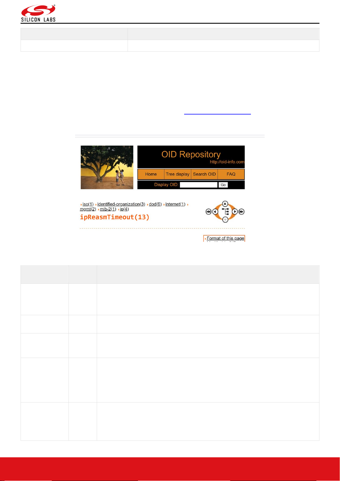
RS9116W Wi-Fi AT Command Programming Reference Manual
Version 2.0
silabs.com | Building a more connected world. 98 | Page
Result Code
Description
ERROR<Error code>
Failure
Response Parameters:
N/A
Possible error codes:
Possible error codes are 0x0021, 0x0025, 0x002C.
Relevance:
This command is relevant when the module is configured in Operating Mode 0, 1, 2 and 6.
To get the Data types of individual OID's, should follow the path http://www.oid-info.com/
Copy the OID except for last digit, paste it on Display OID. It gives Data type, description and information about
OID's.
The list of example OIDs are:
OID
Data
Type
Description
1.3.6.1.2.1.1.1.0
String
A textual description of the entity. This value should
include the full name and version identification of
the system's hardware type, software operating-system,
and networking software.
1.3.6.1.2.1.4.3.0
Counter32
The total number of input datagrams received from interfaces, including those received
in error.
1.3.6.1.2.1.4.4.0
Counter32
The number of input datagrams discarded due to errors in their IP headers, including
bad checksums, version number mismatch, other format errors, time-to-live exceeded,
errors discovered in processing their IP options, etc..
1.3.6.1.2.1.4.5.0
Counter32
The number of input datagrams discarded because the IP address in their IP header's
destination field was not a valid address to be received at this entity. This count
includes invalid addresses (e.g., 0.0.0.0) and addresses of unsupported Classes (e.g.,
Class E). For entities which are not IP routers and therefore do not forward datagrams,
this counter includes datagrams discarded because the destination address was not a
local address..
1.3.6.1.2.1.4.6.0
Counter32
The number of input datagrams for which this entity was not their final IP destination,
as a result of which an attempt was made to find a route to forward them to that final
destination. In entities which do not act as IP routers, this counter will include only
those packets which were Source- Routed via this entity, and the Source-Route option
processing was successful.
Page 99

RS9116W Wi-Fi AT Command Programming Reference Manual
Version 2.0
silabs.com | Building a more connected world. 99 | Page
OID
Data
Type
Description
1.3.6.1.2.1.4.7.0
Counter32
The number of locally addressed datagrams received successfully but discarded
because of an unknown or unsupported protocol.
1.3.6.1.2.1.4.9.0
Counter32
The total number of input datagrams successfully delivered to IP user-protocols
(including ICMP).
1.3.6.1.2.1.4.10.0
Counter32
The total number of IP datagrams which local IP user- protocols (including ICMP)
supplied to IP in requests for transmission. Note that this counter does not include any
datagrams counted in ipForwDatagrams..
1.3.6.1.2.1.4.11.0
Counter32
The number of output IP datagrams for which no problem was encountered to prevent
their transmission to their destination, but which were discarded (e.g., for lack of buffer
space). Note that this counter would include datagrams counted in ipForwDatagrams if
any such packets met this (discretionary) discard criterion.
1.3.6.1.2.1.4.12.0
Counter32
The number of IP datagrams discarded because no route could be found to transmit
them to their destination. Note that this counter includes any packets counted in
ipForwDatagrams which meet this `no-route' criterion. Note that this includes any
datagrams which a host cannot route because all of its default routers are down.
1.3.6.1.2.1.4.13.0
Integer
The maximum number of seconds that received fragments are
held while they are awaiting reassembly at this entity.
1.3.6.1.2.1.4.14.0
Counter32
Number of Internet Protocol (IP) fragments received which needed to be reassembled
at this entity.
1.3.6.1.2.1.4.15.0
Counter32
Number of Internet Protocol (IP) datagrams successfully re-assembled.
1.3.6.1.2.1.4.16.0
Counter32
Number of failures detected by the IP reassembly algorithm (for whatever reason:
timed out, errors, etc.). Note that this is not necessarily a count of discarded IP
fragments since some algorithms (notably the algorithm in RFC 815) can lose track of
the number of fragments by combining them as they are received.
1.3.6.1. 2.1.4.17.0
Counter32
Number of Internet Protocol (IP) datagrams that have been successfully fragmented at
this entity.
1.3.6.1.2.1.4.18.0
Counter32
The number of Internet Protocol (IP) datagrams that have been discarded because
they needed to be fragmented at this entity but could not be, e.g. because their Don't
Fragment flag was set.
1.3.6.1.2.1.4.19.0
Counter32
Number of Internet Protocol (IP) datagram fragments that have been generated as a
result of fragmentation at this entity.
1.3.6.1.2.1.5.1.0
Counter32
The total number of ICMP messages which the entity received. Note that this counter
includes all those counted by icmpInErrors.
1.3.6.1.2.1.5.2.0
Counter32
The number of ICMP messages which the entity received but determined as having
ICMP-specific errors (bad ICMP checksums, bad length, etc.).
1.3.6.1.2.1.5.8.0
Counter32
The number of ICMP Echo (request) messages received.
1.3.6.1.2.1.5.9.0
Counter32
The number of ICMP Echo Reply messages received.
1.3.6.1.2.1.5.14.0
Counter32
The total number of ICMP messages which this entity attempted to send. Note that this
counter includes all those counted by icmpOutErrors.
1.3.6.1.2.1.5.15.0
Counter32
Number of ICMP messages which this entity did not send due to problems discovered
within ICMP such as a lack of buffers. This value should not include errors discovered
outside the ICMP layer such as the inability of IP to route the resultant datagram. In
some implementations there may be no types of error which contribute to this counter's
value.
1.3.6.1.2.1.5.21.0
Counter32
The number of ICMP Echo (request) messages sent.
1.3.6.1.2.1.5.22.0
Counter32
The number of ICMP Echo Reply messages sent.
Page 100

RS9116W Wi-Fi AT Command Programming Reference Manual
Version 2.0
silabs.com | Building a more connected world. 100 | Page
OID
Data
Type
Description
1.3.6.1.2.1.6.5.0
Counter32
The number of times TCP connections have made a direct transition to the SYN-SENT
state from the CLOSED state.
1.3.6.1.2.1.6.6.0
Counter32
The number of times TCP connections have made a direct transition to the SYN-RCVD
state from the LISTEN state.
1.3.6.1.2.1.6.7.0
Counter32
The number of times TCP connections have made a direct transition to the CLOSED
state from either the SYN-SENT state or the SYN-RCVD state, plus the number of
times TCP connections have made a direct transition to the LISTEN state from the
SYN-RCVD state.
1.3.6.1.2.1.6.8.0
Counter32
The number of times TCP connections have made a direct transition to the CLOSED
state from either the ESTABLISHED state or the CLOSE-WAIT state.
1.3.6.1.2.1.6.10.0
Counter32
The total number of segments received, including those received in error. This count
includes segments received on currently established connections.
1.3.6.1.2.1.6.11.0
Counter32
The total number of segments sent, including those on current connections but
excluding those containing only retransmitted octets.
1.3.6.1. 2.1.6.12.0
Counter32
The total number of segments retransmitted - that is, the number of TCP segments
transmitted containing one or more previously transmitted octets.
1.3.6.1.2.1.6.14.0
Counter32
The total number of segments received in error (e.g., bad TCP checksums).
1.3.6.1. 2.1.6.15.0
Counter32
The number of TCP segments sent containing the RST flag.
1.3.6.1.2.1.7.1.0
Counter32
The total number of UDP datagrams delivered to UDP users.
1.3.6.1.2.1.7.4.0
Counter32
The total number of UDP datagrams sent from this entity.
1.3.6.1.2.1.7.3.0
Counter32
The number of received UDP datagrams that could not be delivered for reasons other
than the lack of an application at the destination port.
Example:
AT Mode:
To respond for string type of SNMP object requested by the remote SNMP server
"AT+RSI_SNMP_GET=1.3.6.1.2.1.1.1.0" the command is :
at+rsi_snmp_get_rsp=4,abcd\r\n
0x61 0x74 0x2B 0x72 0x730x69 0x5F 0x73 0x6E 0x6D 0x70 0x5F 0x67 0x65 0x74 0x5F 0x72 0x73 0x70 0x3D 0x34
0x2C 0x61 0x62 0x63 0x64 0x0D 0x0A
Response:
OK\r\n
0x4F 0x4B 0x0D 0x0A
For, OID of type INTEGER, COUNTER, COUNTER64, GAUGE, TIMER_TICKS input shall be given in hexaequivalent form.
To respond for INTEGER type of SNMP object requested by the remote SNMP server
“AT+RSI_SNMP_GET=1.3.6.1.2.1.1.3.0” the command is :
for Integer value 6:
HEX EQUIVALENT:
61 74 2B 72 73 69 5F 73 6E 6D 70 5F 67 65 74 5F 72 73 70 3D 32 2C 06 0D 0A
For Integer value 10:
HEX EQUIVALENT:
61 74 2B 72 73 69 5F 73 6E 6D 70 5F 67 65 74 5F 72 73 70 3D 32 2C 0A 0D 0A
For Integer value 276:
HEX EQUIVALENT:
61 74 2B 72 73 69 5F 73 6E 6D 70 5F 67 65 74 5F 72 73 70 3D 32 2C 14 01 0D 0A
For, OID of type IP_ADDRESS, if the response ip-address want to give is 192.168.10.163 the command shall be
given in HEX form as shown below:
0x61 0x74 0x2b 0x72 0x73 0x69 0x5f 0x73 0x6e 0x6d 0x70 0x5f
 Loading...