

Page 1
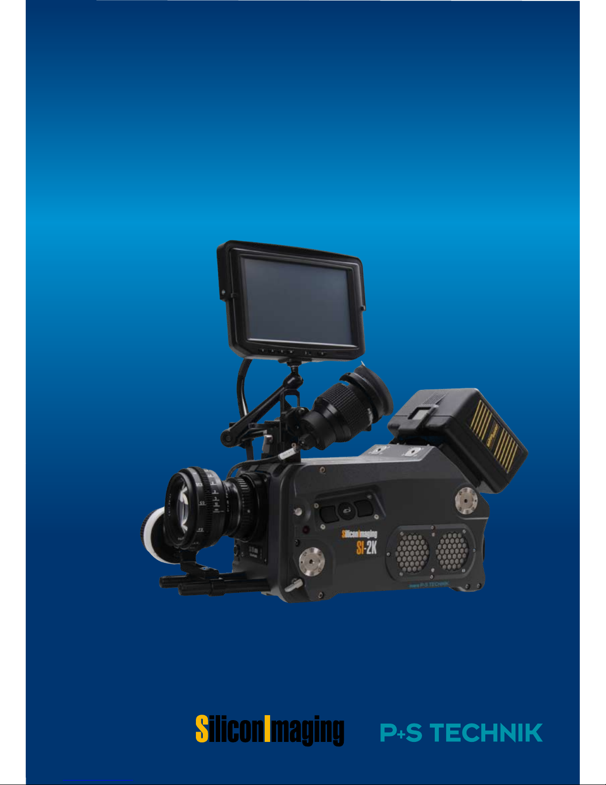
Thank you for purchasing this Silicon Imaging/P+S Technik
Product. Before operating this unit, please read the Instruc-
tions carefully to ensure best possible performance.
Art.No. 22709 v0807
User Manual
SI-2K Digital Cinema Camera
Page 2

2 SI 2K Manual
Page 3

Introduction 3SI 2K Manual
Introduction
The SI-2K Digital Cinema Camera and SI-2K Mini Camera Head are camera
systems operating in conjunction with SiliconDVR software.
SiliconDVR Software controls the SI-2K Mini from either the Recording Unit or
a PC Laptop/Workstation. Silicon DVR is preinstalled on the Recording Unit
and auto-starts by switching on the Recording Unit.
The device is designed to be controlled by a touchscreen monitor. Therefore all
dedicated control buttons at the camera have been removed. All features can
be controlled by the SiliconDVR Software interface via touchscreen, built-in
Mousepad or common IT driven input devices such as keyboard and mouse.
This is a new approach in camera control and user interface.
Thank you for purchasing the SI-2K camera,
P+S Technik and Silicon Imaging
Page 4

SI 2K Manual
Read all of these instructions carefully.
Keep these instructions.
Heed all warnings.
Follow all instructions.
Do not use this apparatus near water.
Clean only with dry cloth.
Do not block any ventilation openings. Install in accordance with the manufacturer’s instructions.
Do not install near any heat sources as radiators, heat registers, stoves, or
other apparatus (including amplifiers) that produce heat.
Protect the power cord from being walked on or pinched particularly at plug,
convenience receptacles, and the point where they exit from the apparatus.
Only use attachments/accessories specified by the manufacturer.
Use only with the cart, stand, tripod, bracket, or table specified by the manufacturer, or sold with this apparatus. When a cart is used, use caution when
moving the cart/apparatus combination to avoid injury tip-over.
Unplug this apparatus during lightning storms or when unused for long periods
of time.
Refer all servicing to qualified service personnel. Servicing is required when the
apparatus has been damaged in any way, such as power-supply cord or plug is
damaged, liquid has been spilled or objects have fallen into the apparatus, the
apparatus has been exposed to rain or moisture, does not operate normally, or
has been dropped.
Do not leave in direct sunlight (or at least cover camera from heavy
sunlight i.e. with flags)
Only use camera in advised temperature range from 0 to +40° Celsius
/ 32°-104° Fahrenheit
Important Safety Instructions
4 Safety Instructions
Page 5
Safety Instructions 5SI 2K Manual
CAUTION
TO REDUCE THE RISK OF ELECTRIC SHOCK,
DO NOT REMOVE COVER (OR BACK).
NO USER SERVICEABLE PARTS INSIDE.
REFER SERVICING TO QUALIFIED SERVICE
PERSONNEL.
CAUTION
RISK OF ELECTRONIC SHOCK
DO NOT OPEN
The lightning flash with arrowhead
symbol, within an equilateral triangle,
is intended to alert the user to the
presence of non-isolated "dangerous
voltage" within the products enclosure
that may be of sufficient magnitude to
constitute a risk of electric shock to
persons.
The exclamation point within an equilateral triangle is intended to alert the
user to the presence of important operating and maintenance (service) instructions in the literature accompanying the appliance.
WARNING
TO REDUCE THE RISK OF FIRE OR SHOCK
HAZARD, DO NOT EXPOSE THIS EQUIPMENT
TO RAIN OR MOISTURE:
CAUTION
TO REDUCE THE RISK OF FIRE OR SHOCK
HAZARD AND ANNOYING INTERFERENCE, USE
THE RECOMMENDED ACCESSORIES ONLY.
CAUTION
TO REDUCE THE RISK OF FIRE OR SHOCK
HAZARD, REFER CHANGE OF SWITCH SETTING INSIDE THE UNIT TO QUALIFIED SERVICE
PERSONNEL.
FCC NOTE
This device complies with Part 15 of
the FCC Rules. To assure continued
compliance follow the attached installation instruction and do not make any
unauthorized modifications.
This equipment has been tested and
found to comply with the limits for a
class A digital device, pursuant to Part
15 of the FCC Rules. These limits are
designed to provide reasonable protection against harmful interference
when equipment is operated in a commercial environment. This equipment,
generates, uses, and can radiate radio
frequency energy and, if not installed
and used in accordance with the instruction manual, may cause harmful
interference in which case the user will
be required to correct the interference
at his own expense.
Replace Battery with part. No. CR2032
only. Use of another battery may present a risk of fire explosion.
CAUTION
Battery may explode if mistreated. Do
not recharge, disassemble or dispose
of in fire.
ATTENTION
At the end of its useful life, under various state and local laws, it is illegal to
dispose of batteries into your municipal waste stream.
Page 6

SI 2K Manual 6 Safety Instructions
Page 7

Contact Information 7
SI 2K Manual
Contact Information
Web Support:
http://www.siliconimaging.com/DigitalCinema/
http://www.pstechnik.de/en/digitalfilm-si2k.php
Support Forum:
http://www.siliconimaging.com/support_forum/index.php
In the U.S.A.:
Silicon Imaging Inc.
17534 Von Karman Avenue
Suite 200
Irvine, CA 92614-6208
USA
Phone: 949-650 1766
Sales: [email protected]
Support: [email protected]
Worldwide :
P+S TECHNIK GmbH
Siemensstraße 12
D-85521 Ottobrunn / München
GERMANY
Tel +49 (0)89 45 09 82 30
Fax +49 (0)89 45 09 82 40
Email: [email protected]
Web: www.pstechnik.de
Contact Information
Page 8

8 Contact Information SI 2K Manual
Page 9

Table Of Contents 9SI 2K Manual
Table Of Contents
Introduction ...........................................................................................3
IMPORTANT SAFETY INSTRUCTIONS .......................................4
Contact Information .............................................................................6
Table Of Contents ................................................................................7
Chapter 1 Delivery Content .............................................................................. 11
Chapter 2 Mechanical Specifications ........................................................13
SI-2K Mini Camera Head .............................................................
13
SI-2K Recording Unit ...................................................................
14
Chapter 3 Quick Start Guide.......................................................................... 17
Mechanical Preperation ...............................................................
18
Inputs & Outputs ...........................................................................
20
Recording Data & Storage ..........................................................
23
Start the Camera ........................................................................... 25
Chapter 4 SiliconDVR Software ................................................................... 31
Software Activation and Licensing ............................................
31
SiliconDVR User Interface ........................................................... 36
Status Information ...................................................................34
Utility Menu ............................................................................... 37
Main Screen .............................................................................. 41
Operating Menu .......................................................................
46
Chapter 5 Look Control ................................................................................... 47
Set Look and Look Library ..........................................................
47
Iridas Color Correction Mode .....................................................
49
Chapter 6 Shooting with the SI-2K ............................................................ 53
Lens Selection ............................................................................... 53
Exposure Control ...........................................................................
55
Apendix A Technical Specifications ............................................................ 59
Dealer and Partner Contacts .........................................................63
Page 10

10 Table Of Contents SI 2K Manual
Page 11
Delivery Content 11SI 2K Manual
Delivery Content
Thank you for choosing SI-2K Digital Cinema
Camera products. Please check your delivery
content with the following parts and accessories
listing and your order confirmation:
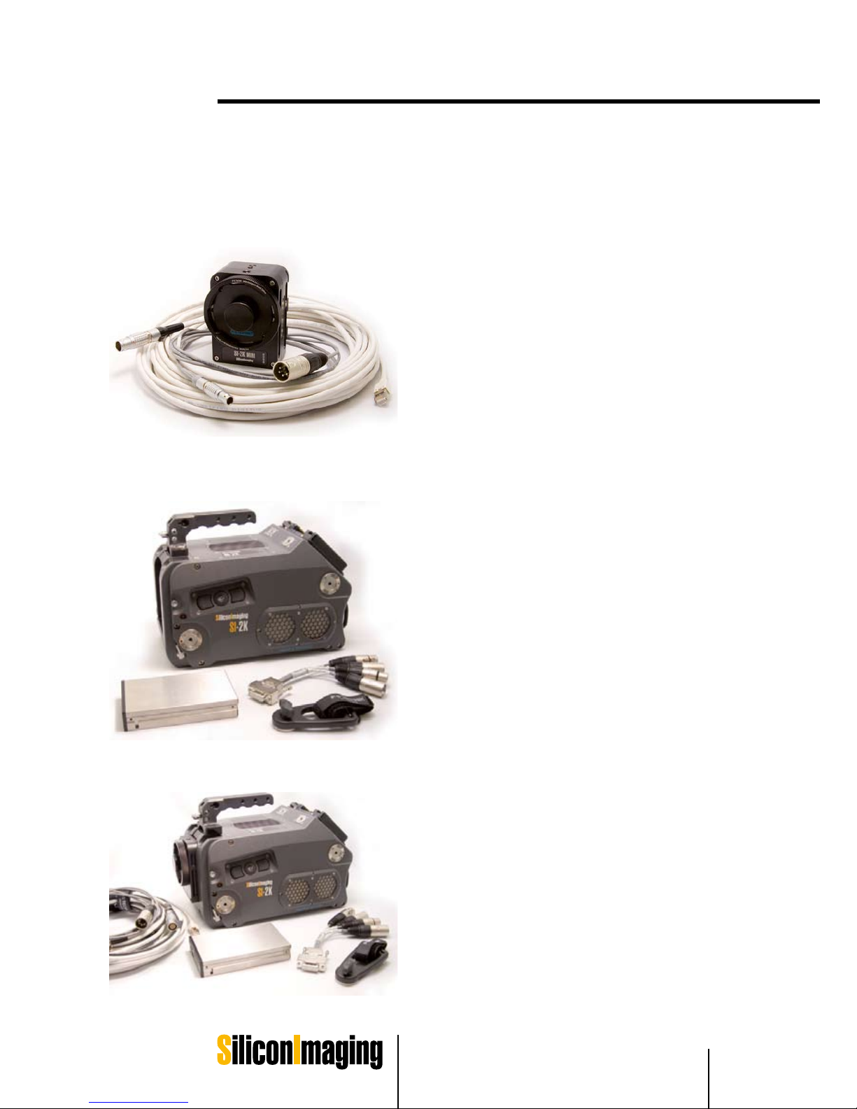
SI-2K Mini Camera Head (#22000)
SI-2K Mini Camera Head equipped with
the IMS (Interchangeable Mount System)
10 m GigaBit Ethernet cable Lemo 12 pin
to RJ45 for Data
connection (#22710)
12 V Power Supply XLR 4 pin (#23327)
2 m Power connection cable Lemo 8 pin
to XLR 4 pin (#22711)
Software License for CineForm RAW
Encoder, Iridas SpeedGrade
Embedded and Silicon DVR
2) SI-2K Recording Unit (#19000)
SI-2K Recording Unit with top handle,
interface for 15 mm rods and quick lock
connection
Mains lead cleat
Audio Adapter Sub D to XLR – 2 channel
IN and OUT (#23405)
3) SI-2K Digital Cinema Camera and
Recording System (#22736)
SI-2K Camera Head (#22000) including
all accessories as mentioned above
SI-2K Recording unit (#19000) including
all accessories as mentioned above
5 m Data & Power Connection cable for
remote connection between
SI-2K Mini Camera Head and SI-2K
Recorder unit Lemo 12 pin to Lemo 12
pin (#23059)
1)
•
•
•
•
•
•
•
•
•
•
•
1
Page 12

12 Delivery Content SI 2K Manual
Page 13
Mechanical Specifications 13SI 2K Manual
Mechanical Specifications
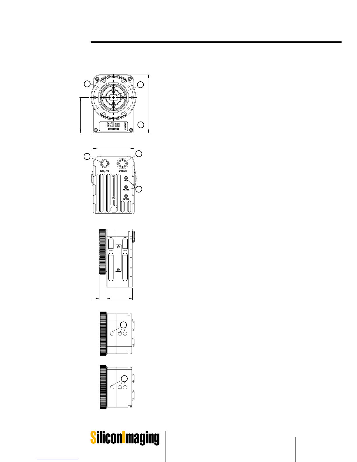
Weight: approx. 550grams
Dimensions: approx. 72mm x 102mm x 58mm(w x h x d)
Power Consumption: 5A/12V DC
IMS Interchangeable Mount System
(for Mounts: PL, B4, Nikon, Canon etc.)
1
2
4
5
6
2/3“ CMOS Sensor 2K with Optical Low Pass Filter
Lemo 8-pin Socket „PWR / CTRL“
(+12V DC Power Supply / Multicam Sync Signal)
Lemo 12-pin Socket „NETWORK“
(Data Connection to Recording Units)
Status LED‘s
3
Serial number SI-2K MINI
SI-2K MINI
SI-2K MINI
LEFT
TOP
BOTTOM
13mm 45mm
72mm
102mm
62mm
FRONT
BACK
1
2
3
4
6
5
7
2 x 1/4“ Screw Threads for Accessories
(i.e. Handle, MiniRig Support Bridge, Tripod Plate, etc.)
SI-2K MINI
7
7
SI-2K Mini Camera Head
1) IMS Interchangeable Mount System
2) 2/3" CMOS Sensor 2K with optical
Low Pass filter
(Frame SIze 10.24 mm x 5.76 mm)
3) Serial number SI-2K
4) Lemo 8-pin socket "PWR/CTRL"
(+12 V DC power supply / multicam
sync signal)
5) Lemo 12-pin socket "NETWORK"
(data connection to Recording Units)
6) Status LED‘s
(data connection to Recording Units)
7) 2 x 1/4 screw threads for accessories
(i.e. side handle, MiniRig support bridge,
tripod plate, etc.)
Weight: approx. 550 grams
Dimensions: approx. 72 mm x 102 mm x 58 mm
(WxHxD)
Power Consumption: 0.5A/12V DC
2
Page 14
14 Mechanical Specifications SI 2K Manual
25
26
26
27
105
N 35
81mm 81mm
36mm36mm
62mm
110
N 16
1
11
3
2
4
5
6
7
8
9
10
11
20
21
22
23
24
211,3
280,50
20,22
Sensor surface to P+S Technik IMS
12
13
14
15
15
16
17
18
19
Page 15

Mechanical Specifications 15SI 2K Manual
2
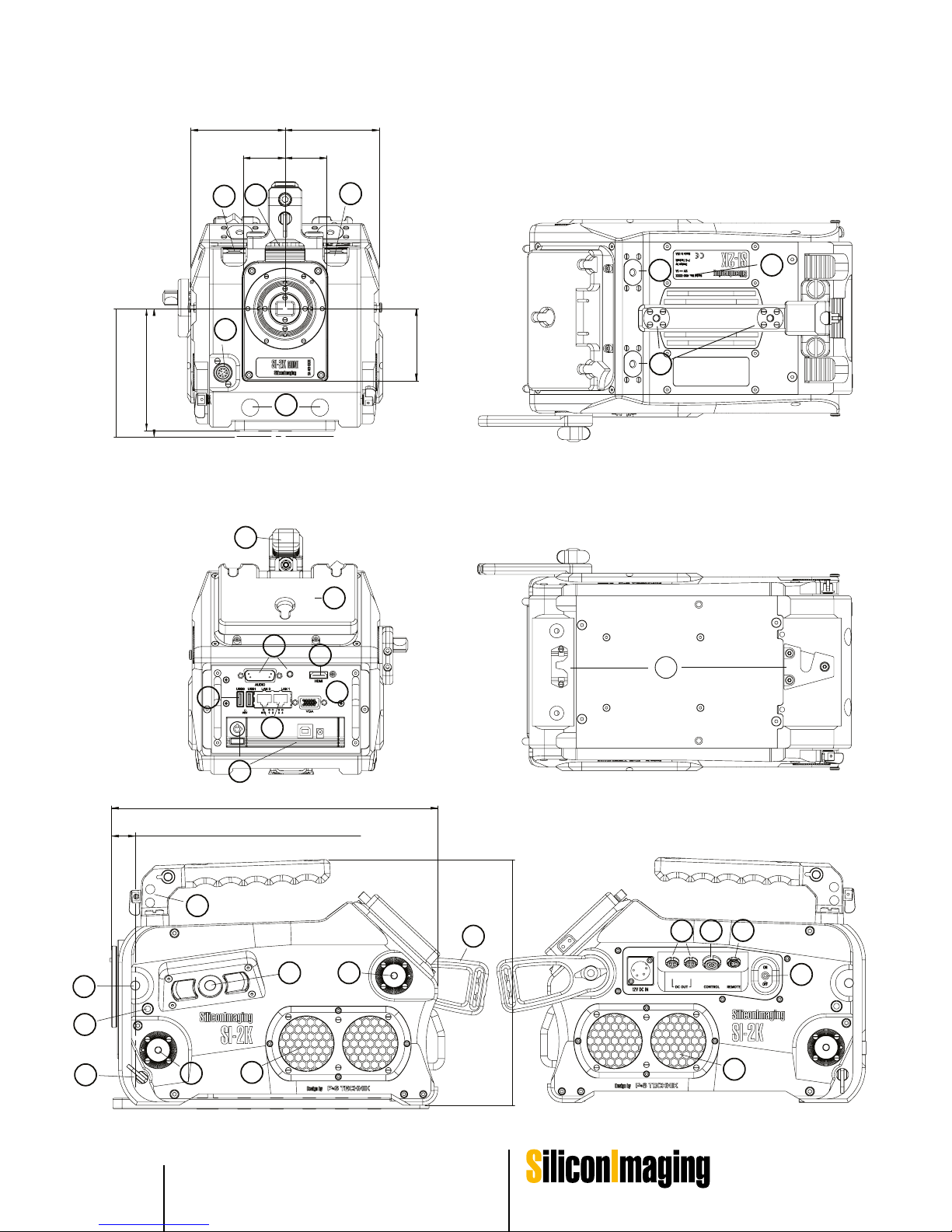
SI-2K Recording Unit
1) SI-2K Mini tray with Camera Head connectors and locker bars
2) Hirose 12-pin (+Batt power)
3) Lightweight support prepared for 15 mm rods
4) Handle with vIewfinder holder mechanics
5) Anton Bauer Gold Mount (Battery Mount)
6) HDMI out (Standard Computer DVI Signal Secondary Monitoring
1280x720 60 Hz)
7) Audio I/O left: Sub-D to Breakout Cable, right: headphones out 3.5 mm
8) VGA out (Primary Monitoring)
9) LAN 0: Gigabit Ethernet DHCP enabled
LAN 1: Gigabit Ethernet data connection to alternate SI-2K Mini
Camera Head
10) 2 x USB
11) Detachable recording media cartridge (i.e. hard disk)
12) Tape hook indicating focal plane of sensor
13) User interface for OnScreen navigation mouse selection
(left button, mouse pad, right button)
14) Tally light
15) Multi-purpose rosettes (hand grip, magic arms, extensions, monitors)
16) Ventilation slots with air filter (AIR-IN)
17) Cable tie bracket
18) Locking clamps for lightweight support rods
19) Multipurpose 3-axis electronic viewfinder mount
20) 2 x DC OUT Lemo 4-pin Socket (5 V regulated/12 V regulated/
Battery Voltage unregulated)
21) CONTROL socket for synchronizing cameras
22) Remote socket for external RUN signal to camera
23) ON/OFF power switch
24) Ventilation slots with air filter (AIR-OUT)
Weight: approx. 6400 grams
(SI-2K Recording Unit + SI-2K Mini + Hard Disk)
Dimensions: approx. 290 mm x 210 mm x 160 mm (WxHxD)
Power Consumption: 5A/12V DC
Page 16

16 Mechanical Specifications SI 2K Manual
Page 17
Quick Start Guide 17SI 2K Manual
Quick Start Guide
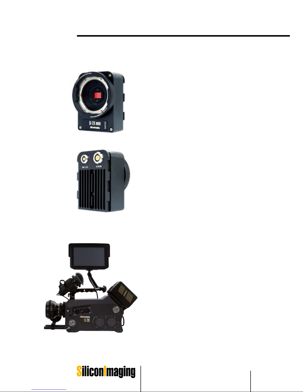
SI-2K Mini Camera Head
The SI-2K Mini is a small camera head with a 2/3”
single chip CMOS sensor working with a Bayer
pattern. The frame size is 10.24mm x 5.76mm (w
x h) (16mm frame: 10.3mm x 7.5mm) (w x h).
The data output of the SI-2K Mini is transfered via
Gigabit Ethernet on a Lemo 12 pin connector for
maximum reliability. A second connector for I/O
and power is also provided.
The mounting system for lens mounts relies on
the P+S Technik Interchangeable Mount System (IMS). The intermediate mount is a precise
modular system that enables the camera operator
to exchange lens mounts in the field in seconds
while maintaining the accuracy required for cinema quality optics.
¼” x 20 mounting holes are provided on both the
top and bottom of the SI-2K Mini for maximum flexibility. On the back cover the SI-2K carries three
LED lights indicating Power (green), Data (blue)
and Record (red). In addition the SI-2K Mini can
easily be attached to the front of a SI-2K Recording Unit.
SI-2K Digital Cinema Camera
System
The SI-2K is a complete camera system consisting of a SI- 2K Mini camera head front end (removable), a processing unit, I/O, removable storage all in a ruggedized housing. The camera runs
the SiliconDVR™ software and records in Cineform RAW™ format on a removable recording media. Many ergonomic options are available – LCD
touchscree n, electronic and optical viewfinders,
shoulder rig, cable sets and other tools to facilitate the use of the camera.
3
Page 18
18 Quick Start Guide SI 2K Manual
Mechanical Preparation
Mounting the SI-2K Mini
camera head
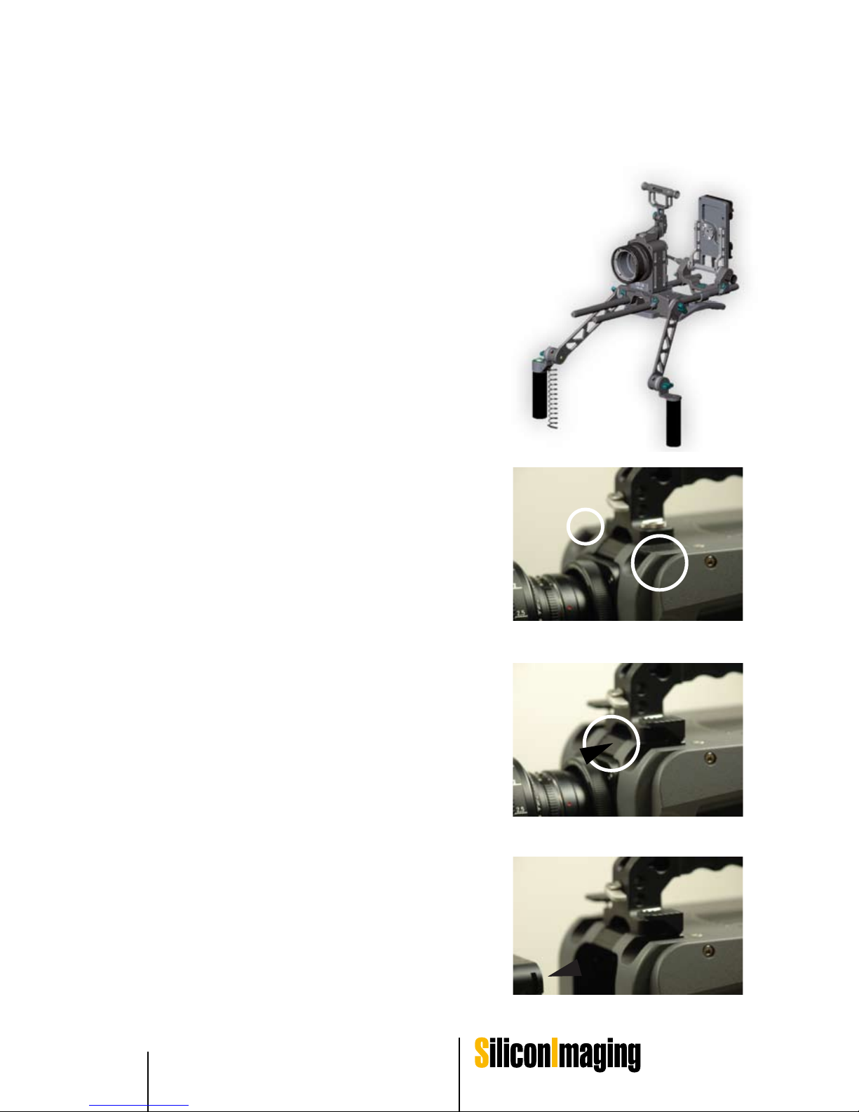
The SI-2K Mini is mounted (i.e. to the SI-2K Mini
Rig, to the ergonomic hand grip or a tripod) either
from the top or bottom by 1/4”x20 mounting holes.
Two mounting holes are provided along with one
alignment hole. Depending on the mounting system, the mounting holes can be used to provide
different spacing between the mounting hole and
alignment pin.
The unused mounting hole (top or bottom) can
be used for accessories such as the ergonomic
hand grip or viewfinder or touchscreen on a flexible arm.
Removing and Inserting the Mini
from the Recording Unit
The SI-2K Mini Camera Head is mounted to the
front of the SI-2K Recording Unit with a special
locking system. After raising the locker bars, the
SI-2K Mini must be manually eased forward until
the power and Ethernet connections are automatically disconnected.
Extension cables can be provided by Silicon Imaging and P+S Technik to operate the SI-2K Mini
tethered to the front of the SI-2K Recording Unit.
1. Pull up Locker Bars
2. Press Fixture Button and pull out the SI-2K
Mini carefully straight.
3. To insert the SI-2K Mini, follow the instructions
in reverse direction.
1.
2.
3.
Page 19
Quick Start Guide 19SI 2K Manual
3
Mounting Accessories to the
SI-2K Recording Unit
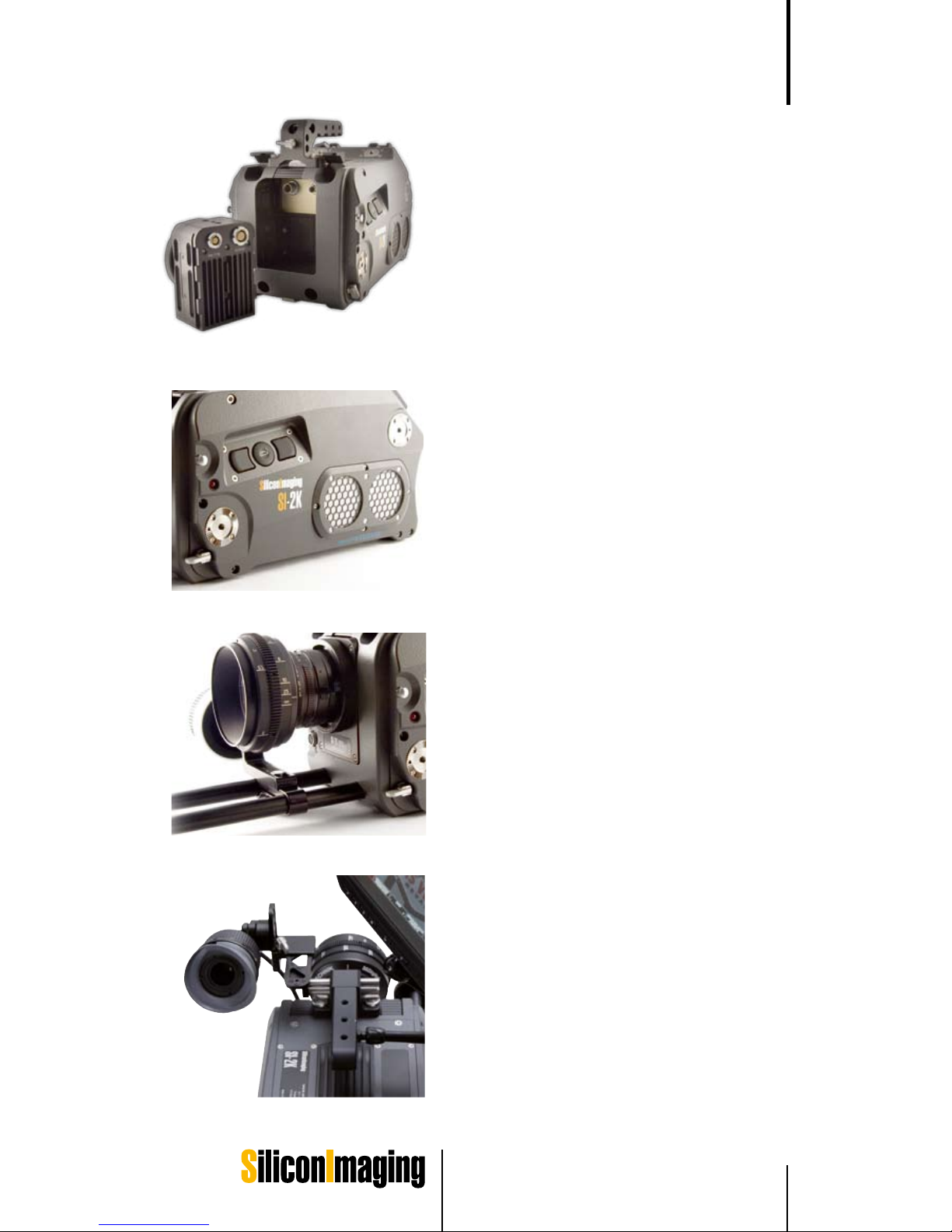
The bottom mount on the SI-2K matches a Sony
Quick-Lock mounting plate. With a baseplate the
Recording Unit can be adapted to various other systems like 16 mm and 35 mm bridge plates
available from Silicon Imaging and P+S Technik.
Rosettes are available at both side, the front and
back of the camera for accessory mounting.
The front of the SI-2K is prepared for lightweight
lens support and accepts 15 mm rods. On the
sides near the front is a small locking lever that
can lock the rods in place.
Handle
The handle provides a well balanced grip for the
camera in addition to a flat top mounting surface
available by 1/4x20” mounting holes. The handle
is removable for top-rigging the camera. In addition a three axis viewfinder holder for the electronic view finder is integrated.
Page 20

20 Quick Start Guide SI 2K Manual
Power
SI-2K Mini Camera Head
For standalone operation, power is applied to the PWR/CTRL, either from a
battery pack such as the Anton Bauer Dionic 90 via the Mini Rig battery holder
or from an AC power supply using the appropriate cable. The data is transmitted over a separate cable from the NETWORK connector to a workstation or
laptop computer.
For operation tethered to an SI-2K Recording Unit, a special tether cable is
used with integrated power and data over the single NETWORK connector.
The purpose of this is to minimize cabling involved in POV shooting.
SI-2K Recorder Unit
External Power
For battery operation, a standard Anton Bauer battery mount is available on
the top rear of the camera. A fully charged AntonBauer Hytron 140 battery will
provide over 2 hours of operation. Other suppliers batteries can be used with
adapter plates.
Alternatively an external +12V DC power can be supplied to the XLR 4-pin
connector on the right rear of the camera. AC power supplies to match the
inputs and connectors required for various countries are available.
Auxiliary power to other devices like the viewfinder or other peripherals can be
taken from the auxiliary power outlets. In battery operation the D-Tap on the
side of the battery mount serves as an additional power connector for accessories as well. Please note that the D-Tap connector is unswitched. Any device
connected to this power source will continue to discharge the battery when
camera is turned off
DC Power output
On the right rear of the camera, adjacent to the +12 V DC IN are two power
connectors for supplying external devices. Each is a locking Lemo connector with 4 pins for +5 V regulated, +12 V regulated, +12 V unregulated and
ground. Adapter cables are available.
The SI-2K provides many of the input and output capabilities that might be
associated with a workstation class computer in a video village scenario. In
addition to the standard camera functions, there are USB 2.0 ports for future
expansion, increased data storage capacity and a secondary DVI(HDMI) video
Inputs & Outputs
Page 21

Quick Start Guide 21SI 2K Manual
3
output capable of display of 720p live video at full resolution.
The SI-2K Mini only requires power and data connections since the remainder
of the functions are provided by the computer attached to the SI-2K Mini.
Power Switch
Please use the power switch on the right side of the camera to power down the
camera prior to removal of the battery pack. Expect a delay of up to 30 seconds
from the time power is applied to the live operation of the camera. Whenever
possible , shut down Windows properly using the Shutdown Icon in your SI
Folder.
Front 12-pin Hirose connector
The 12-pin hirose on the front of the SI-2K provides power input for B4 lens
servo motors mounted on the camera using the B4 lens adapter.
Monitoring
Monitoring option with the SI-2K should be conceived as pure Video-Assist
Function. Due to recording performance it is only a low-res representation of
the high quality picture recorded. For realtime display of the hi-res stream (up to
2K) captured, a low quality and low resolution debayer algorithm is used to display the image. On Set it is proven to be sufficient for focus and framing control
supported by several focus assist functions provided inside SiliconDVR.
NOTE: If recording in quad (preview) mode please note that the camera is
designed as a film camera and focus pulling classically has to be achieved via
tape based markings.
Monitoring with the SI-2K Recording Unit:
Primary Monitoring:
The VGA Port carries the Primary Display which is able to show the SiliconDVR
User Interface and Recording Information.
8.4" LCD Touscreen Monitor
The 8.4” LCD Touchscreen monitor requires a VGA video input (VGA connector on the rear panel of the SI-2K Recorder Unit), USB connection (rear panel)
for touchscreen operation and power (available on the non-operator side panel). The 8.4" LCD Touchscreen monitor includes an active VGA signal splitter
and offers an additional VGA output i.e. for use with the electronic viewfinder.
Electronic Viewfinder
The electronic viewfinder requires a VGA video input (VGA connector on the
rear panel of the SI-2K Recorder Unit) and power (available on the non-operator side panel).
Note:
If using the electronic viewfinder at the same time as the LCD Touchscreen,
use the additional VGA output on the back of the LCD monitor to connect the
•
•
Page 22

22 Quick Start Guide SI 2K Manual
viewfinder.
Secondary Monitoring:
The HDMI signal is used to show the secondary display which is a representation of the image recorded, it shows up without user interface and can be
turned on and off inside SiliconDVR user interface. The HDMI Port at the SI-2K
Recording Unit carries a DVI Signal (1280 x 720 @ 60Hz). By using off-theshelf HDMI to DVI Converters every kind of DVI Monitor can be fed.
There are manufacturers who provide solutions to convert the resulting DVI signal to HD or SD SDI video signal (i.e. Doremi DSDI-20 ). Please be aware that
the SI-2K is rather designed as a Digital Cinema Camera than for purposes as
a video camera.
Notes on the HDMI Port:
If your DVI or HDMI monitor does not work instantly at the HDMI Port, please
quit SiliconDVR application and manually restart it again. If it still does not work,
the output device does not support given resolution and/or frequency. Please
also note, that using the HDMI Port instead of splitting the VGA signal for monitoring slows down overall performance !
Audio
Audio input is provided on the 15-pin ‘D-sub’ connector at the top of the electronics bay. An adapter cable terminates in two XLR connectors for stereo
microphone inputs and two XLR connectors for stereo output. Note that these
are not balanced inputs and should only be considered for scratch audio. Internal acquisition runs at 16 bit, 48 KHz per channel.
For quality recording, the M-Audio MobilePre external audio interface has been
tested and is compatible with the SI-2K. Other audio devices are not supported by the camera and SiliconDVR.
A 1/8” stereo headphone jack for sound monitoring is provided to the right of
the microphone connector.
Page 23

Quick Start Guide 23SI 2K Manual
3
Recording Data and Storage
SI-2K Mini Camera Head
In addition to supplying power, the PWR/CTRL connection can be used for an
external RECORD switch input and for hardware synchronization of multiple
cameras using special cables provided by the manufacturer.
The NETWORK input is a standard Gigabit Ethernet data path using a more
rugged Lemo connector for better data integrity. Cables are available in various
lengths that terminate in:
- a male RJ-45 connector for input into a computer or a laptop or the LAN 1
connector on the backside of the SI-2K recorder unit
- a female Lemo for tethered use with an SI-2K Recorder Unit – in this case
power for the SI-2K Mini head is provided via the same cable
The maximum length of the connection is 30 m when the camera head is powered through this connection and 100 m if only data is transferred. Then the
camera heads needs to be power from battery or mains on shorter distance
into the PWR/CTRL socket.
SI-2K Recording Unit
The SI-2K Recording Unit is delivered with one removable hard disk carrier
(Digital Standard Magazine) and a 160 GB hard disc for recording. The media
carrier is connected to the SATA bus system of the Recording Unit.
The supplied Digital Standard Magazines are compatible with any 2.5” laptop
hard discs, 5400 rpm or faster. Bear in mind that faster drives might be more
useful when connected to an editing station, but will reduce battery life and
generate more heat in the SI-2K.
Additional carriers, also for different media like i.e. RAID hard disk setups or
solid state memory (Digital Raid Magazine, Digital Magazine SSD), are available from P+S Technik or Silicon Imaging. Please read the FAQ section on
Recording and Storage on our website for more information.
NOTE : Please swap drives during turned-off state of the camera !
Optional Recording Media
Optional carriers can support two hard discs enabling Raid use in Level 1 (Mirror for Security) and 0 (Stripe for Performance) as well solid options in the near
future.
Page 24

24 Quick Start Guide SI 2K Manual
In addition, any mapped hard disk can be used for recording. This includes any
device that are connected via the external USB ports. Be sure that any external
drive supports a sustained throughput of 40 MB/sec. Two extra USB 2.0 ports
are available on the back.
IMPORTANT:
If you want to use additional USB recording devices on the SI-2K please always add and remove them on and from the RUNNING SYSTEM (hot plug).
Do NOT perform a reboot with any USB storage device attached to the SI-2K!!
For more information please refer to the chapter Notes on Write Protection
Filter.
Ethernet
Two gigabit Ethernet ports are available on the rear of the camera for future
use. These will be used for integrating the camera into a fully networked video
village (LAN 0) for file transfer and camera control of an attached SI-2K Mini
Head (LAN 1).
Files and File system
There are two ways recording RAW Data from the Camera.
1. Uncompressed RAW at a Data Rate of up to 100 MB/sec (approx.) resulting in *.siv files.
For displaying images recorded in this format, the IRIDAS Product Line
(www.iridas.com) supports both *.siv and cineform *.avi.
2. CineFormRAW (compressed) at a maximum data rate of currently 30 MB/
sec (approx.) resulting in *. avi or *.mov files.
For displaying images recorded in this format, the free decoder plugin Neo
Player (http://www.cineform.com/products/Downloads/DownloadNEOPlayerStart.htm) can be installed to run CineForm decoded movie files inside
Windows Media Player or Quicktime Player Applications.
The standard file system on the disk enclosed by the exchangeable hard disk
carrier must be formatted in NTFS.
Compressed CineForm RAW:
160 GB will approximately record 90 minutes at lowest compressed data
rate (1 GB = 1024 MByte; recording time depends on settings and picture
information).
Uncompressed:
160 GB will approximately record 25 minutes in uncompressed mode.
(1 GB = 1024 MByte; recording time depends on settings and picture information).
Page 25

Quick Start Guide 25SI 2K Manual
3
Start the Camera
Connect Accessories like Viewfinder or VGA or DVI Monitor.
Connect Powersupply or Battery
Dock your Magazine and Turn it on with the knob at the docking frame.
Switch on the SI-2K Recording Unit
Boot time takes about one minute.
Camera Operation
To operate the camera either use the LCD Touchscreen functionality or in addition use the integrated mouse pad on the left side of the camera body. The
sealed mouse pad is provided with a joystick-style cursor control and left and
right mouse buttons. This enables the camera operator to make selections
when no touchscreen is available (such as when only the electronic viewfinder
is used).
In addition USB operating tools like a computer mouse, track ball or keyboard
can be used with the SI-2K Recording Unit when connected to the USB connectors at the rear of the camera.
Create a Project
After Silicon DVR has started, browse to UTILITY MENU > NEW PROJECT and
name a project on Harddrive D:\. Make sure, that the recording Harddisk is not C:
Note:
Read more about the Utility Menu in Chapter SiliconDVR Software > Software
Operation
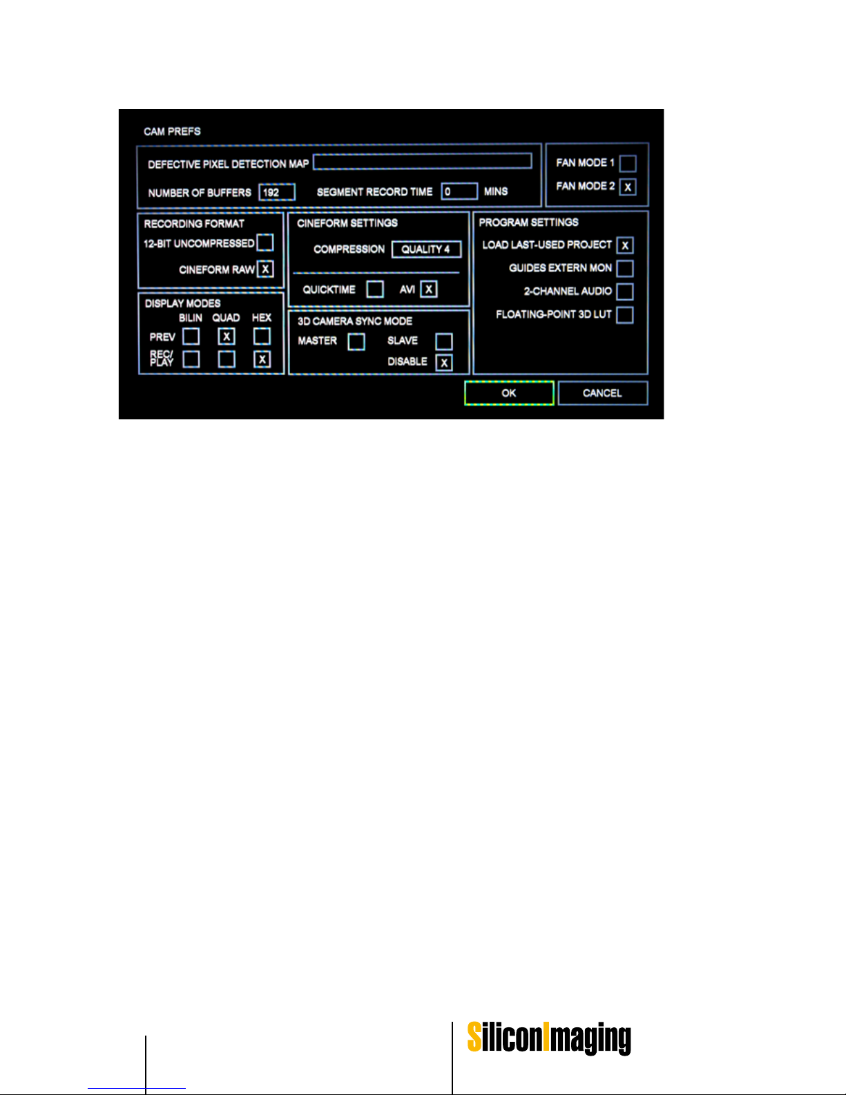
Browse to UTILITY MENU / CAM PREFS and change following recommended Settings for the current Versions of SI-2K Recording Unit running v571 of SiliconDVR:
FAN MODE = 2
QUALITY = 4
CINEFORM RAW
DISPLAY PREV = QUAD
DISPLAY REC/PLAY = HEX
•
•
•
•
Page 26
26 Quick Start Guide SI 2K Manual
IMPORTANT:
Please note, that the software is designed for cross system use. That means
that functionality could exceed recording systems which are restricted in performance. That makes the system futureproof in terms of upgrade options, but
the user has to be careful in choosing settings.
Inside SiliconDVR go to UTILITY MENU/CAM PREFS to access Recording
and View Settings.
Notes on CAM PREFS Settings:
Overall Performance and Stability of the System are depending on the Settings you choose inside CAM PREFS. Especially Display Modes combined
with Resolutions and Framerates.
Confirm CAM PREFS with OK and EXIT UTILITY MENU to access RECORD
Button.
Notes on Fan Mode Settings:
FAN MODE 1 varies the fan-speed based on the processor temperature. So at
low temps, the fans run slower (and are quieter), and when the temps are hot,
they run faster. This mode is good to use when outside or in hot environments.
The processor has a protection mechanism that down-clocks the processor if
it goes over 100C. Also recording is disabled when you hit 100C. So there
are no worries about frying the processor (there is also a temp indicator in the
status bar that lets you know the temp of the processor).
FAN MODE 2 keeps the fans running full-blast when not recording, and quiets
them when recording. In fan mode 1, when it‘s hot, the camera does not get
quieter when you‘re in hot temps, but if you are in a sound-critical environment,
Page 27

Quick Start Guide 27SI 2K Manual
3
this can pose a big problem. Fan mode 2 will keep the fans quiet no matter
what, although again, recording will stop at 100C. But once recording stops,
the fans kick in at full-speed to keep the camera as cool as possible before the
next recording.
Set Resolution and Frame Rate
Browse to RESOLUTION / FRAME RATE and choose i.e.:
2048 x 1080 @ 25p
Confirm RESOLUTION / FRAME RATE with OK
After that, the System will prompt to “SET BLACK”. Close Lens and Iris to
Set Black with for all Gains. If not, please choose “SET BLACK” manually.
Set Black
NOTE: better set black more often than prompted as the fixed pattern noise
changes with the temperature of the camera !
Cover the lens with the lens cap
Browse to MAIN MENU and press SET BLACK
Tick the check box, if you want to SET BLACK for all gains
Press OK to start process, remoce lens cap only after process is finished
SET BLACK calibrates the black level of the sensor, performing a correction
of any fixed pattern noise and column-to-column variations created from inconsistencies in the analog-to-digital conversion process, as well as removing any
hot or deviant pixels. Fixed pattern noise on a CMOS sensor looks like a fixed
„screen-door“ effect, or like fixed vertical lines going down the image, and is
typically visible in darker or gained up portions of the image.
All CMOS sensors have this attribute, but because this fixed pattern noise is a
black pure offset, it can easily be removed through a subtraction process which
the SET BLACK operations performs. Furthermore, Altasens CMOS sensor
designs exhibit extremely low amounts of fixed pattern noise, further enabling
the SI-2K to maintain clean blacks after a calibration operation.
After a SET BLACK operation, SiliconDVR saves the black frame for that resolution on the disk, so that it can be recalled the next time you boot the program
or swich modes. This prevents the user from having to repeatedly cover the
lens and SET BLACK. It also saves a listing of deviant pixels that are masked
out, preventing them from being embedded in the recorded RAW files.
•
•
•
•
•
•
•
Page 28
28 Quick Start Guide SI 2K Manual
The frequency of having to SET BLACK will depend on the shooting environment and the subject matter. Typically after approximately five minutes from a
cold boot, the camera will reach a temperature stabilization point where any
further deviation will be insignificant compared to that which occured in the
first five minutes.
Another black recalibration may not be necessary for hours thereafter, espcially
if one is shooting complex scenery or brighter scenery that is not against dimly
lit flat white subject matter (where fixed pattern noise, if it‘s apparent will typically be the most visible). If one is shooting in hot environment, or is changing
the environment rapidly, black recalibrations may be necessary.
Also for dark scenes where the shadows are gained up higher, black recalibration may be required more often to make sure that there are no inconsistencies
in the blacks with fixed pattern noise that gain may result from temperature
variations within the camera as it runs.
SiliconDVR and Operating System
SiliconDVR Software is a Windows Application. The SI-2K Digital Recording
Unit runs an embedded Windows Version.
SiliconDVR Interface has been designed to record and playback files and to
embed metadata such as non-destructive colour information or timecode.
The Interface is mainly designed for touchscreen use for smooth and quick
operation. However it is also possible to control it via mouse or touchpad systems.
Page 29

Quick Start Guide 29SI 2K Manual
3
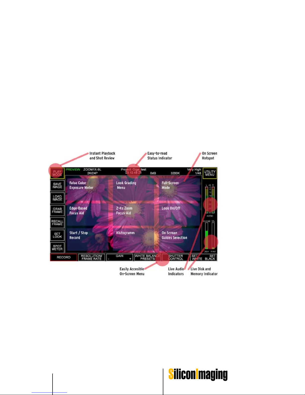
Note:
The on-screen Hotspots inside the picture area are touch sensitive for quick
access tools for focus and exposure control.
The picture below shows the arrangement of the hot spots. For a detailed explanation of tools and the menu structure of SiliconDVR in general refer the the
chapter SiliconDVR > User Interface
False Color Exposure Meter:
Luminance Distribution in a Scene on a pixel per pixel basis. Red is clipped and
therefore overexposed. “Colour Temperature” shows the Luminance. Black/
Blue “cold” analog to low luminance, Orange/Red “warm” analog to high luminance.
Edge based Focus Aid:
Objects in Focus are marked in Red Color, whereas the rest of the picture is
turned grey.
Star/Stop Record:
Record Hotspot
Look Grading Menu:
Embedded IRIDAS Colorgrading Interface.
Focus Aid Zoom:
Zoom and pan around for critical Focus adjustments.
Histogram:
A Histogram is displayed in the bottom of the screen to measure the overall exposure. As the Histogram graphically overlays the Recording Preview Picture,
the overall performance will drop. Do not use the Histogram permanently.
Full Screen Modes:
Different Fullscreen Modes to switch on/off the User Interface are accessible
here.
Look On/Off:
on/Off Toggel for 3D LUT defined in SET LOOK
On Screen Guides Selection
On Screen Guides features Overlay Masks of 16:9, 1.45:1, 2.39:1, 4:3 Safe
Area ratios.
After quitting SiliconDVR (UTILITY MENU – QUIT) , the Windows Desktop
shows up. A “SI” Folder on the Desktop links all necessary Windows Functions
such as Windows Shutdown or ActivateRaw.exe.
Page 30

30 Quick Start Guide SI 2K Manual
Look Control
The idea behind Iridas Looks is to SIMULATE the color characteristics of the
target medium such as a Filmprint or even an HD Monitor, since the RAW image itself looks flat.
Please note
that this is only a tool to simulate colors inside the SiliconDVR without affecting
the RAW Image itself! Iridas .look files represent non-destructive color metadata based on 3D look up tables in a 32-bit floating point environment.
These can be modified with the integrated Iridas Speedgrade Version, which
can be accessed through the hot spot button upper middle of the preview image.
Optional the .look files can be generated with the IRIDAS Software such as the
Speedgrade Product Family and imported to the SI-2K Recoding Unit through
USB connection.
SiliconDVR already carries preset .look files (C:Program Files\ Silicon Imaging\Silicon DVR\Data\*.look
Exposure Control
ISO Rating
The CMOS sensor in the SI-2K is approximately „daylight“ balanced for 5600K
at ISO 160.
When shooting green-screen or blue-screen footage, in order to prevent higher
digital gains (that in-turn produce higher noise) in the blue and green channels
in order to match the response of the red channel, it is suggested to shoot
with daylight balanced light-sources. Also daylight balanced light-sources will
extend the „useable“ dynamic range of the image around 1/3 to 1/2 f-stop (because the red-channel will not clip first).
With Tungsten Lighting and shooting at 3200K the sensitivity is approx. ISO
250.
Shutter
To convert from a shutter based on a time-based method (such as 1/Xth of a
second) to a shutter based on a degree angle correlating to the spinning reflex
mirror of a film camera, use this equation:
1 / [ ( 360 degrees / Target angle ) * Target Frame Rate ] = Time based shutter
(in 1/Xth of a second format)
So for instance, a 180 degree shutter at 24fps will equate to:
1 / [ ( 360 degrees / 180 degress ) * 24 ] = 1/48th of a second
A 144 degree shutter angle at 24fps will equate to:
1 / [ ( 360 degrees / 144 degrees ) * 24 ] = 1/60th of a second
Page 31

SiliconDVR Software 31
SI 2K Manual
SiliconDVR Software
Software Activation and Licensing
There are two levels of software activation required for a fully operational workflow:
the CineForm RAW encoder that works in conjunction with the SI-2K DVR
application to encode the video stream, and the CineForm editing tools for
your editing suite.
Silicon DVR is the Control Center for Recording and Camera Setup. A requirement to run Silicon DVR on the Camera or on a separate Workstation is
the License and the Activation.
If you have purchased a Recording Unit by P+S Technik, the embedded SiliconDVR runs an activation personally licensed to you.
It should already be activated ! Do NOT deactivate by yourself.
If the license does not run on your device, please contact helpdesk@pstechnik.de.
SiliconDVR is shipped with a Cineform Serial Number with a limited number
of activations ( 3 Activations): CFR2K-XXXXXXXXXX .
Activation is the important step to a working license and needs Serial Number
and the System Code and a Name for referring the Activation.
This kind of activation is valid for Silicon DVR Version 1.571 and lower Versions.
Cineform Activation is needed to run SiliconDVR Application.
If SiliconDVR is not activated
You need a separate Internet Connection Line. Do not use Internet Connection on your Recording System with Silicon DVR Software installed to prevent
misuse or virus attacks (Recording Unit or laptop/workstation). If you would
like to deactivate or reactivate Licenses on the Recording Unit
1)
4
Page 32

32 SiliconDVR Software SI 2K Manual
How to de-activate or re-activate SiliconDVR
Note:
Please note, that you only have limited number of activations, you can activate
your SiliconDVR three times. For re-use please take care to properly deactivate your system. We strongly recomend to contact our technical support team
before de-activating or re-activating your license.
Please email to [email protected]
What shall I do if SiliconDVR is not activated
You need a separate internet connection line. Do setup an internet connection
on your SI-2K Recording System with Silicon DVR Software installed to prevent misuse or Virus Attacks. (Recording Unit or Laptop/Workstation).
If you would like to deactivate or reactivate licenses on the SI-2K Recording
Unit follow these steps:
Run ActivateRaw.exe
C:\Program Files\ CineForm\CineformRAW-2K-Codec\ActivateRaw.exe
If activated the pop up window shows Name, Serial Number, Activation
Key, System Code. The System Code is generated randomly and automatically on your system at that time. These are unique fingerprints of your hardware
system
If not activated, please go to http://www.cineform.com/register.html and
follow the instructions. Make sure you correctly type your email address, as
the activation code is sent to you via email. Iif you consider to use our support
and helpdesk, please always carboncopy or forward activation code with your
product serial to [email protected]
Remember exact User Name given carefully since it is case and letter
sensitive
Transfer emailed Activation Code and User Name into the popup window
textfields and press activate.
Please note
that you only have limited number of activations. For re-use please take care to
properly deactivate your system.
Only exception to connect your recording system to the internet it to reach the
activation server for deactivation of your license! We recomend to contact our
technical support team before deactivating your license - [email protected]
1)
2)
3)
4)
5)
Page 33

SiliconDVR Software 33SI 2K Manual
4
Notes on Write Protection Filter
Quit SiliconDVR (UTILITY MENU – QUIT), the Windows Desktop shows up.
A folder named "SI" on the desktop links to all necessary Windows Functions
such as Windows Shutdown or ActivateRaw.exe. The “Write Filter” toolset to
turn on and off the Write Filter is situated here.
Why do we need a Write Filter?
In order to give the system a much higher reliability the software is equipped
with a Write Filter that protects the whole internal system drive (path c:\) of
SI-2K from having new data written on it.
This provides additional protection against corruption after the operating systen (OS) has booted and prevents recordings to be stored directly on the
internal system drive (path c:\), which would fill up the drive and shuts down
the camera.
When does the user need to disable the Write Filter?
Normally you do not need to touch the write filter function.
IMPORTANT:
In normal operation mode the Write Filter MUST be “enabled” all the time –
otherwise you run into danger of a corrupted software image and therefore a
complete breakdown of your SI-2K camera. Even with enabled write protection
you can change all settings within the SiliconDVR software.
There are three occasions when the Write Filter must temporarily be disabled:
1. Upgrade to a new version of SiliconDVR (lean or full installation)
2. CineFormRAW Activation
3. Any changes need to be performed by a user on the system like monitor
resolution
How to deactive/reactivate the Write Filter?
IMPORTANT:
Systems will be shipped with FBWF enabled – it should be enabled for normal
camera operation.
- Write Filter can be disabled by clicking on the short cut in the SI folder, “Disable Write Filter and Reboot” (Note that to change the state of the Write Filter,
you cannot do a power off shutdown, only a normal shutdown)
- After the automatic reboot, the Write Filter will be disabled and SiliconDVR
can be upgraded, the CineForm key inputted or any other necessary changes
on the system can be performed
Page 34

34 SiliconDVR Software SI 2K Manual
- After these activities are completed in disabled mode, there is another shortcut, “Enable Write Filter and Reboot”. Selecting that will re-enable the Write
Filter and reboot. After the reboot, the Write Filter will be enabled and the
system will be ready for normal use. The state of the Write Filter (enabled or
disabled) can always be determined by opening a console window and typing
“fbwfmgr”.
Restriction when using USB storage for recording
There is a conflict between the BIOS setting of the SI-2K camera and the Write
Protection Filter on the system drive (CF Card - path c:\). So when attaching
an additional USB recording Device (like a USB thumb drive/ USB stick/ USB
HDD) besides the SATA drive in the internal 2.5“ Drive slot AND rebooting the
system, the Write Protection for the system drive (CF Card - path: c:\) of the
SI-2K gets mixed up. At the same time recording onto that additional USB storage device is not possible.
Solution
If you want to use additional USB recording devices on the SI-2K please always add and remove them on and from the RUNNING SYSTEM (hot plug).
Do NOT perform a reboot with any USB storage device attached to the SI2K!!
Cineform RAW™ Encoder
For the SI-2K Digital Cinema Camera, the encoder will already be activated at
the factory and nothing else needs to be done by the user. Up to 3 computers
can be activated for recording at one time. Activations can be removed at the
registrations website.
For the PC user, after the SiliconDVR software is installed, there will be a
CineForm directory added to the start menu. A program called ActivateRAW
must be run on the machine that will do the capturing. ActivateRAW will create
a system code (“finger print”) for this computer. Then, go to the registration
site: http://www.cineform.com/register.html and enter this system code
(“finger print”), serial number, company name, and e-mail address. An activation key will be e-mailed to the email address provided. Enter the Name and
Activation Code into the ActivateRAW dialog EXCACTLY as they appear in the
activation e-mail you received, and an activation confirmation message should
appear. If the encoder is updated there should be no need to reactivate the
new version.
Page 35

SiliconDVR Software 35SI 2K Manual
4
Prospect 4K
Note: Any editing suite used in conjunction with a CineForm tool should be
installed prior to the CineForm application.
Once installed, run the Activate.exe utility located in the Windows Start Menu:
Start > All Programs > CineForm > Prospect4K
Copy the 8-digit System Code from the dialog box. Then, go to the registration
site: http://www.cineform.com/register.html and enter the system code,
serial number company name, and email address. An activation key will be
emailed to the address provided.
When you have received the activation code, run the Activate.exe utility and
enter both the Name and Activation Code exactly as they appear in the email
you received, and an activation confirmation message should appear.
NOTE: If your machine does not have Internet access you can still activate by
managing the Internet transactions on any machine that does have Internet access.
Neo 4K and Prospect 4K License Notes
The Neo 4K and Prospect 4K software are each licensed for operation on one
machine at a time. The licenses can be moved easily from one machine to another by deactivating the first machine and activating a second machine. Visit
www.cineform.com/register.html for details.
When using the integrated SI-2K camera, when the SI-2K Mini is detached
from the front of the SI-2K, SiliconDVR can still be used for recording on up to
three total computers (including the SI-2K Recording Unit). To record with the
same SI-2K Mini on a workstation or laptop, a second CineForm RAW software license must be procured from Silicon Imaging.
Page 36

36 SiliconDVR Software SI 2K Manual
SiliconDVR User Interface
SiliconDVR consists of three main user interface screens to make general settings, operate the camera and playback recorded clips. In the following the
three menu screens UTILITY MENU, MAIN MENU and PLAYBACK MENU
and their tools are described in order of first use.
The Status Information is visibly in all three menu screens.
Status Information
Status indicators are placed at the top of the screen to indicate the current
settings and mode of the camera.
Preview / Play / Record Mode
Displays the current operating mode of the camera.
Zoom/Mode/Resolution/Rate
Displays the zoom level (1-4), quadlet (Q) or bilinear (B) display and the present frame size and frame rate.
Project / Timecode
Displays the current project name and time used for the file timestamp.
Gain
The current gain setting
White Balance
Displays which of the presets or a user defined white balance LUT.
Compression
Displays the compression mode selected in the Utility menu.
Shutter Speed
Displays the current shutter speed
Page 37

SiliconDVR Software 37SI 2K Manual
4
Utility Menu
Always leave the MAIN MENU and go to the UTILITY MENU, when you first
start the camera to make the basic settings and create a project name. Access the UTILITY MENU from the upper right corner of the MAIN MENU.
Each time the Record mode is entered, a new file will be created in the Project
directory with a file name of the project followed by a timestamp. This creates
an easy sequence of takes automatically.
Camera Preference Menu (CAM PREF)
Basic information about the operation of the camera is set in this menu.
Number of Buffers
This is the number of frame buffers used by the DVR to store incoming camera
data prior to Cineform RAW™ encoding. These buffers can be used to extend
recording time when the encoder can not maintain the rate of incoming data –
encoding continues and the buffers slowly fill until recording must be stopped
to allow the buffer to empty. This is important for high frame rate shooting, 2K
modes and scenes with a very high level of complexity as this slows the encoding process. TAKE CARE ! The number of buffers you choose diverging from
the default setting could impact camera‘s stability.
Defective Pixel Detection Map
Most defective pixels are automatically found and replaced using the black
reference. If known pixels are bad, a separate file indicating each bad pixel can
be created. The format is a tab delineated text file with an x coordinate, <tab>,
y coordinate <cr> for each bad pixel.
Default Boot Frame-Rate / Resolution
This is the default value for the camera and may be set to new values elsewhere.
Cineform RAW Compression Quality
Adaptive Mode) The adaptive recording mode will dynamically change the
compression to meet the scene complexity, maximizing the quality setting while
preventing the RAM buffer from overflowing. So if the camera changes to Quality level 1, it will, when presented with a scene that can be recorded at Quality
4, increase the quality back up that higher setting. After a recording is finished,
the last recording quality setting is used as initial starting point. Should a scene
have changed radically, the recording will very quickly go back up to Quality
4 once the recording starts back up. You will not be „stuck“ at Quality 1 if the
scene can be encoded at a higher quality setting.
•
•
•
•
Page 38

38 SiliconDVR Software SI 2K Manual
Quality 4) 3.5:1, or approximately 18-20MB/s from a 2K/24P stream at 0db
gain.
Quality 3) 5:1 compression, or approximately 15-16MB/s from a 2K/24P
stream at 0db gain.
Quality 2) 8:1 compression (approx), or approximately 10MB/s from a 2K/24P
stream at 0db gain.
Quality 1) 10:1 compression, or approximately 8MB/s from a 2K/24P stream
at 0db gain.
12 Bit Uncompressed
Uncompressed raw sensor data (as opposed to Cineform RAW™ ) is streamed
to the hard disk. If the disk access rate cannot keep up with the incoming video
data rate, then the RAM buffer will fill and, once filled, stop the recording. Data
rates depend on frame rate and resolution, but require up to 100 MB/sec.
The following check boxes provide a method for controlling the operation of the
camera and software on startup.
Load Last Used Project
When checked, the camera will automatically add the next recording to the
previously selected project files, appending the current date stamp.
Auto Load Preferences
The state of the camera when last used is stored and automatically restored
when the camera is restarted.
Auto Save Black Image
The last used black image is used for the next camera restart. Otherwise, the
operator will be prompted to capture a new black image for each time the camera is restarted.
Audio
The camera or computer audio inputs are sampled at 48 kHz, 16 bits per sample, two channels. Any device may be used as long as it is able to operate as a
standard Windows audio device, showing up in the Windows Device Manager.
This includes many (but not all) Firewire and USB audio interfaces.
External Display
A second high resolution monitor can be connected. It is possible to display
full HD on this monitor for real-time viewing. Typically a 1280x720 DVI monitor
is connected and enabled in the Windows settings menu. This button will then
enable the live output interpolated by either the quadlet or bilinear methods.
The bilinear will take more system resources (CPU time) so it is important to
have sufficient resources available.
•
•
•
•
•
•
Page 39

SiliconDVR Software 39SI 2K Manual
4
Project Setup
The Open Project and New Project buttons allow the user to create a new
project or open a previously existing project.
New Project
The project setup screen selects the location for the main project file (<project>.sil) and all of the individual captures. The project can be stored on any
drive - exepect the system drice C:\ - with a drive letter mapped into the system
representing an internal, external or network share as long as the continuous
throughput to the drive is at least 15MB/sec.
IMPORTANT:
Do not use the C: drive as this is the system drive. Filling up this drive will disable recording.
The directory tree is negotiated by selecting subdirectories to move down the
tree or the double dot (..) to move up one level. The onscreen keypad is used
to enter a project name.
For computer operation, the keyboard can be used for file name entry.
Open Project
Use this menu to access an excisiting project saved on a drive
Timecode Settings
Type: Record Run
The timecode increments only when recording; i.e. the clock does not increment if not in recording mode.
Type: Free Run
The timecode always increments.
Source: Preset
This mode uses the timecode setting from the Preset Timecode Settings dialog
area. Can be used in record or free run modes.
Source: Slave LTC
The preset timecode settings in the dialog section area ignored. The timecode
is read from the external Adrienne USB time code reader.
Source: Time of Day
In this mode, the PC clock is used.
Preset TimeCode Settings
This section is used to input the timecode.
•
Page 40

40 SiliconDVR Software SI 2K Manual
Color Bars
A standard color bar pattern can be sent to the display monitors – both the
internal and an external. This pattern assists the user in doing a color alignment.
A properly aligned monitor is strongly suggested in conjunction with 3D LUT
‘looks’ to view the actual look as it will appear.
Flip Image
Ground glass converters require that the incoming video image be flipped, top
to bottom or left to right for correct viewing.
Quit
When using the SI-2K Mini with a laptop or workstation, this will exit the DVR
application. <ctl> Q can also be used.
Serial Com
The camera head (SI-2K Mini) and the DVR are separate functional units. The
SI-2K Mini has an internal processor running camera firmware. The control is
over a virtual serial interface transmitted via the gigabit interface. For testing
purposes, it is possible to send commands directly to the camera, bypassing
normal GUI interfacing. This should only be done as suggested by P+S and
SI.
Load Firmware
The firmware in the SI-2K Mini can be updated in the field. On occasion the operator may be provided by SI with a file. This file is pointed to by Load Firmware
and will be automatically sent to the SI-2K Mini head for updating.
Page 41

SiliconDVR Software 41
SI 2K Manual
4
Main Operation Menu
Black Setting
During the initial use, the software will detect a lack of a black reference image and automatically requests the capture of a reference:
Completely cover the lens and click on OK. This performs two functions. First,
the image black level is set for every pixel. Second, a bad pixel map will be created for any pixels that are outside of the normal range of offsets and corrected
automatically in the RAW file.
There are two control areas of the viewfinder. First is the set of touch buttons
surrounding the live display. Second, for the most often used operator functions, there is a nine location ‘hot spot’ grid superimposed on the viewfinder.
More information on this and other aspects of the main screen are described
in a section below.
Set White/Set Black
Set Black has been described above for setting both the black level and bad
pixel map. White balance allows the user to create a unique white balance
table based on the current image. A white card exposed to approximately a
70% level occupying 100% of the image area is placed in front of the lens
and the SET WHITE is selected. Alternatively, the loupe can be used for more
localized metering.
White Balance Presets
There are standard white balance presets to approximate the temperature of
typical lighting conditions. If a user white balance is created, this is added to
the list of options.
Gain (+/-)
The analog gain of the camera is incremented and decremented from -3dB to
12 dB in increments of 3 dB. More gain provides more light sensitivity at the expense of increased image noise, analogous to increasing ISO ratings of film.
Page 42

42 SiliconDVR Software SI 2K Manual
Resolution/Frame Rate
The standard resolutions supported are 2K (2048x1152 / 2048x1080 /
2048x856 ), 1080p (1920x1080), 720p (1280x720), 540p (960x540).
For 2K, the supported frame rates are 23.976 and 24fps. For 1080p, the supported frames rates are the same as 2K plus 29.97 and 30fps.
For 720p, the frame rate is currently 72fps. An upcoming software release will
add 12, 18, 21, 23.976, 24, 25, 30, 48, 50, 60, 72 to the already existing 85
fps.
In time-lapse mode, every N th frame is captured. For example, if the frame rate
is set to 24 fps and the Nth frame is set to 48, one frame will be captured every
two seconds.
Shutter Control
The shutter speed of the electronic shutter is selectable over the range of
1/48th of a second to 1/500th of a second.
Syncro-Scan Offset
To synchronize with monitors and fine tune the shutter speed, syncro-scan offsets the start of the exposure time in the frame. Every increment moves the start
of the frame exposure (shortening the exposure time) by X lines.
Extended Shutter Mode
The exposure time can be extended over multiple frames in this mode.
Record
The Record button or Record hotspot initiates recording in the currently selected mode. The file is saved in the project directory previously selected and
the name that will be saved is the current project name, data and time as an avi
file. If the buffer fills to capacity, recording will stop and the existing captured
video will be saved. Recording can begin once the buffer has been filled.
Status Information in Main Menu
Audio
The audio level for the stereo inputs selected at the operating system level is
shown. Level adjustments are done through the sound control panel that is
part of Windows or with whatever toolkit was provided with the sound capture
hardware. An indicator shows with the sound level has reached clipping.
Page 43

SiliconDVR Software 43SI 2K Manual
4
RAM Buffer Indicator
The buffer space allocated in the CAM PREFS menu is used to buffer the incoming video. This buffer space is shown visually and numerically. When the
buffer is filled, the recording operation will stop. No data to that point will be
lost but no further data can be recorded until the buffer is emptied to disk.
The buffer gauge is an excellent troubleshooting tool. A slowly rising buffer indicates that the CPU is not able to compress the incoming data at a fast enough
rate. A very rapidly filling buffer usually indicates that the disk system is not accepting data at a fast enough rate. This is typical for uncompressed mode.
RAM Buffer Overflow
The on-board RAM buffer prevents any dropped frames from occurring during
capture. Should disk speed in the case of Uncompressed 12-bit recording or
the processor speed in the case of CineForm RAW recording not be capable
of keeping up with the recording rate, eventually the RAM buffer will be consumed, and recording must stop. When this occurs a message box appears
notifying the end-user that the RAM-buffer que is being written out to disk.
After the RAM buffer is flushed and the recorded contents are safely written to
disk, the live preview will resume. This functionality ensures that files are always
safely written out to disk, and with enough RAM also allows under-powered
machines to safely record in uncompressed 12-bit or high-resolution CineForm
RAW.
Remaining Disk Space
The amount of available disk space on the currently selected disk is shown.
The potential for problems recording increase as the disk reaches capacity.
Because a disk is a series of concentric circles rotating at a fixed speed, the
write speed slows as you reach inner tracks. Also, if the disk has been used a
number of times and has had individual files erased, the disk can become fragmented, again slowing the access rate.
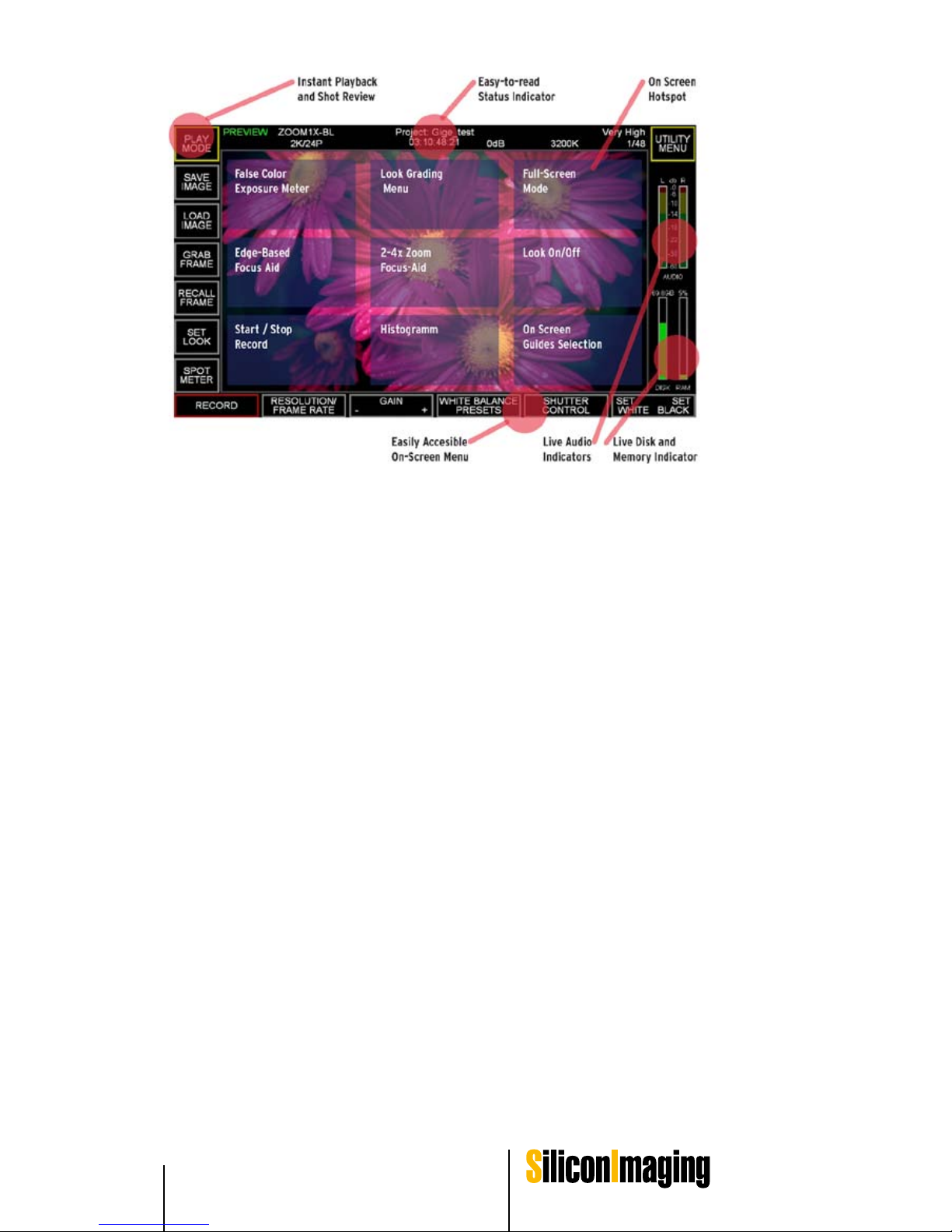
Hot Spots on the Preview Screen
Hot spots are nine areas in an invisible tic-tac-toe pattern in the main viewing
screen. Each area either toggles a function on and off or sequences through a
series of options for that mode.
The basic layout is:
False Color Exposure Zone Meter
Zebra or pseudo-color is an exposure tool. Unlike the spot meter, which gives
you the exact exposure in a small area, zebra divides the exposure into ranges
and provide a visual indication for the entire image.
The meaning of each color is shown by the key in the metering area.
Page 44
44 SiliconDVR Software SI 2K Manual
Edge-Based Focus Assist
When the focus assist is enabled, a real-time Sobel edge detector is run.
As an edge in the picture turns redder, it is in better focus. This is because the
edge is sharper. This does not mean that the smoother areas are out of focus,
just that they have no well defined edges.
Record
A recording can be begun either by using the touch button Record at the lower
left or by using the hot spot in the lower left. In either case, the word RECORD
will show in the upper left and continue until the hot spot is hit again. The clip
will automatically be saved to a file with a file name comprised of the project
and the time the recording began.
Look Control Menu
In this menu you can adjust your .look files with the intergrated color correction
tools. Please refer to the chapter LOOK CONTROL for further information.
Zoom
To assist in focusing, a centered zoom mode is available. Each time the center
of the screen is selected, the image cycles through a zoom of 1x, 2x, and 4x.
The level of magnification is shown on the upper status bar.
Using the widgets on the screen during the zoom mode allows the user to
scroll around the zoomed in window.
Page 45

SiliconDVR Software 45SI 2K Manual
4
Histogram
A real-time histogram is displayed across the bottom of the image.
Individual channels of red, blue and green are shown. This is a total histogram
of the image showing the number of pixels (vertical axis) vs. the digital value
from dark to bright on the horizontal axis.
Full Screen
Full screen sequences through three states. These are the standard display
with all menus and information, a maximized viewfinder with basic project information superimposed and maximized viewfinder with no information.
In all of these modes, the hotspots are still active.
Look On / OFF
Enables or disables the look (3D LUT) feature. This feature applies to display
only – recorded data will not have the look stored as metadata.
On-Screen Guides
If the final output format is known, guide bars can be added to the screen to
assist in creating video that can be cropped while maintaining the required field
of view. Multiple taps on the hot-spot toggle through a series of guides. These
guidelines have no effect on the recorded frame resolution or picture area.
Page 46

46 SiliconDVR Software SI 2K Manual
Additional Tools
Spot Meter/Loupe
A 10 pixel by 10 pixel section of the display is enlarged with a 4x zoom. This
spot meter shows the average luminosity within the enlarged area.
If a white balance is done while the spot meter is active, only the white region
within the loupe is used for the white balance.
Frame Store Operations
There is a single frame buffer that can be used for previewing of compositing
effects and single frame capture. Since is only one buffer available, loading a
new image into the frame-store buffer erases the older image that was currently in the buffer. The controls for the frame-store are on the upper left-hand
side of the main screen.
Save Image
The current image in the preview is stored as a dng, jpg, dpx and bmp format
in the current project directory.
Load Image
A bmp file is loaded into the frame buffer. Note that only *.bmp files can be
read.
Grab Frame
The current live image is loaded into the frame buffer.
Recall Frame
Three display modes are cycled by repeated selection of Recall. Live video,
frame buffer image and a 50% live/buffer composite are shown. This composite does not effect recorded video.
Playback Menu
Within Play mode, the most recent clip recorded can be played back or a previously generated clip can be loaded using the Load New File button. In either
case files are played in the viewfinder.
A timeline is shown at the bottom of the display that can be clicked on to see
different portions of the clip.
Export DNG
The current clip is exported to DNG format using the same filename.
Page 47
Look Control 47SI 2K Manual
Look Control
5
Set Look and Look Library
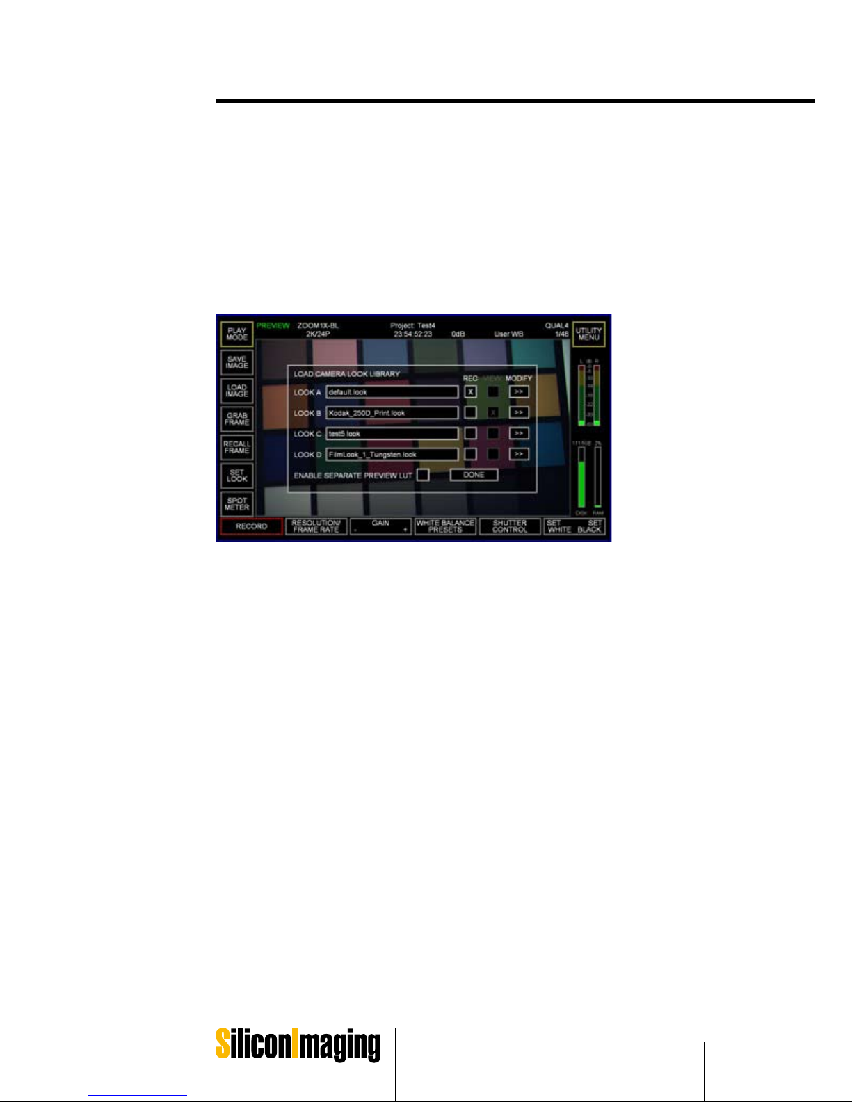
The SET LOOK command opens the LOAD CAMERA LOOK LIBRARY. Inside
this library control panel are a selection of up to 4 .looks that can be loaded and
quickly selected between, and also controls for modifying those looks, selecting preview and record LUT‘s, and managing which .look files are placed inside
of a project‘s folder for inclusion with recorded files.
LOOK A, B, C, D are the four looks that are made available for quick-switching
between look files without having to go into the file system browser in order
to select a look file each time one is desired. Also all .look files that are loaded
into this library control panel are copied into the project directory so that any
.look that was potentially used on-set is also available with the recorded files
in post-production/editing. If the user selects a new file to load into the library
from the file system, or modifies and saves a new .look file, at the time of adding
the .look to the list (replacing what was there), that new .look is added to the
project directory. The older .look file that was replaced is not deleted from the
recording project directory, so that any .looks that could have been recorded
with files in the project directory are safely maintained.
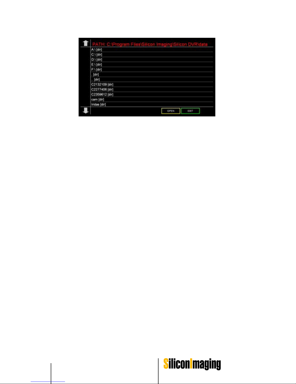
In order to load up a new .look file into slots A, B, C, or D, simply click on the
name of the file and the file-browser will open into the /SilconDVR/Data/ folder
of the recording machine. If there is another location where you want to load
the .look file from (such as a thumb-drive), simply browse to that new location
using the file browser directory controls (the .[dir] and ..[dir] selection at the
top of the file-browser screen or the drive selection letters). If a .look is loaded
from another directory that is not the /SiliconDVR/data directory, SiliconDVR
will automatically copy that LUT into the /data directory for future use so that
the user will not have to continually browse to remote directories just to call up
the same .look file.
Page 48
48 Look Control SI 2K Manual
There are two important columns of note in the LOOK LIBRARY, the REC
and VIEW selection columns. When the ENABLE SEPARATE PREVIEW LUT
check-box is selected, this allows the end-user to select a different .look file
for recording and embedding as metadata in the header of the AVI/QT file,
versus what will be viewed on screen. Typical use of this application is for users who want to record with a LOG or RAW LUT (so that files that are on-disk
when they are played back or imported into editorial or color-correction have a
LOG LUT applied), but want to view a „normal“ print-style LUT in the preview
window during shooting. This separation allows the record LUT to not have the
effects of the preview LUT „baked“ into the LUT that is applied to the metadata
of the recorded AVI/QT file. It also aids workflows that are based on a filmcalibration system that requires Cineon LOG input. In this situation, a user will
set a Cineon-style LUT for the record LUT, but preview with a LUT that has a
reverse Cineon curve. The cinematographer, director, and any other viewers
will see the „end-result“ on-screen during shooting, but the recorded files will
have the appearance of a Cineon-calibrated file. When these files are imported
into a system with a proper Cineon-reversal LUT, they will appear „normal“
again. If the user were to apply the preview LUT to the recorded files, it would
interfere with the Cineon-reversal LUT in the post editing bay that was expecting Cineon-LOG input. Should a situation like this occur though, because the
LUT‘s are metadata, they can be swapped out in post to calibrate the files to
whatever standard is needed.
When swapping between LOOKS A, B, C, and D, the image in the preview and
on the external monitor will change live with each selection, aiding the user in
selecting the correct LUT. After the selection process is complete, the user can
press the DONE button and proceed with recording.
Page 49
Look Control 49
SI 2K Manual
5
IRIDAS Color Correction Mode
Hitting the MODIFY button in the LOOK LIBRARY will open up the IRIDAS
color-correction control panel. This control panel has a powerful set of comprehensive controls that allows the end-user to color-correct the preview image in
real-time to obtain the look for the image they desire in-camera. It utilizes the
same 32-bit floating point color-correction engine of the IRIDAS SpeedGrade
OnSet family for high-precision color-correction operations.
The IRIDAS color-correction control panel is split into three main areas: 1) the
control panel modes and metering indicators, 2) file management and luminance separation controls, and 3) the control surface itself.
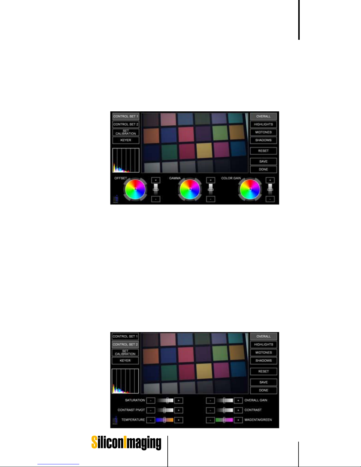
There are a total of three control surfaces to chose from with CONTROL SET
1, CONTROL SET 2, and the KEYER. Each of the two main control sets (1
and 2) are segmented between controlling the entire luminance range with
the OVERALL control, or isolated to just the HIGHLIGHTS, MIDTONES, and
SHADOWS.
CONTROL SET 1 comprises the hue-offset color-wheels and controls for color offset (additive), gamma, and color gain.
CONTROL SET 2 has additional controls over color temperature, contrast/
pivot, overall gain, and saturation.
Page 50

50 Look Control SI 2K Manual
Right-clicking on any of the color-adjustment widgets activates a „virtual trackball“ mode. This allows the user to move the mouse around like a trackball
control for fine increments of the image. This is especially effective with the
color-hue wheels in CONTROL SET 1. To exit the virtual trackball mode, rightclick a second time.
Clicking on the histogram indicator swaps between a live histogram and a
vectorscope. An important note about the histogram and vectorscope in the
IRIDAS control panel is that unlike the indicators in the main GUI, these IRIDAS-specific indicators reflect the values of the look applied to the RAW image data, not the underlying RAW values like the main GUI indicators. This is
because the main GUI indicators are ideally suited for measuring the exposure
of the RAW image data, where-as the histogram and vectorscope in the IRIDAS control panel allows the user see how their color-correction is affecting
the final image. Clipping that happens during exposure is unrecoverable, hence
the indicators in the main GUI cover the RAW data only. If the RAW data is not
clipped, then clipping from the .look file can be recovered in post. Therefore for
the main GUI it is vital that the user have live information on the exposure level
of the RAW data and not the effects of the .look file which can be misleading
for actual exposure-level of the RAW image data.
The general workflow the IRIDAS color correction mode is that a user loads a
pre-existing .look file (typically the current .look file) into the LOOK LIBRARY,
and then modifies it using the MODIFY button associated with that look. Alternatively the IRIDAS control panel can be opened by clicking on the top-middle
hot-spot, at which point it will modify the current .look.
The control panel uses the current .look XML to set the color-correction controls as an initial base for starting a color-correction from. So for instance, if
the gamma and color-gain operations were modified in the .look XML, the initial
screen when loading the IRIDAS control panel would reflect those changes to
those controls in the interface color-wheels and sliders.
When the user has completed a color-correction, it is very important to first
press the SAVE button in order to save-out a new .look file. Then the user can
press the DONE button and see their new .look in the main GUI and replaced
in the LOOK LIBRARY slot. At this time it is also copied into the main project directory for access in post-production. Simply pressing the DONE button cancels the current correction and exits the IRIDAS control panel with no
modification to the .look file.
Page 51
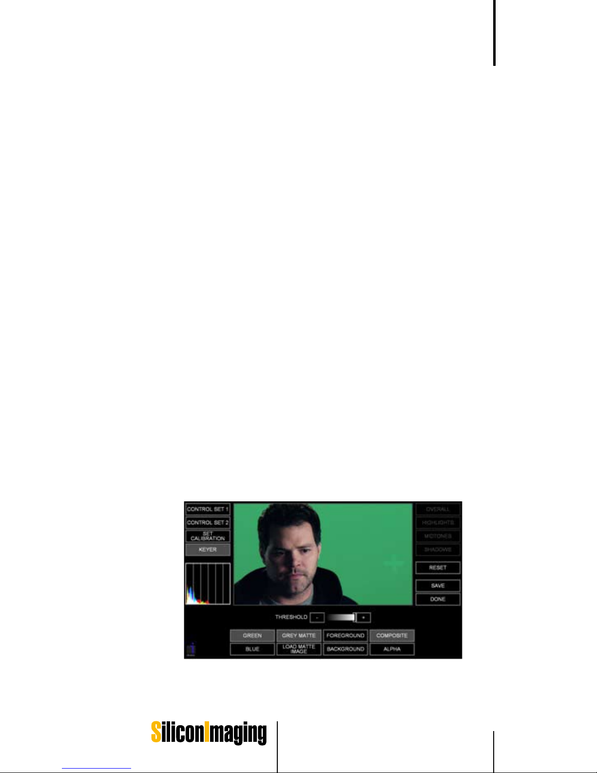
Look Control 51SI 2K Manual
5
Keyer Module
The Keyer mode in the IRIDAS color correction panel is a special mode that
allows users to preview keys on-set in the context of the subject they are shooting. Keys can be set on either green or blue-screen using a real-time RGB
difference keyer, and backgrounds can be composited behinds subjects to
give the shooter an indication of how a final key and composite in post will
look. „Problem Areas“ and other green or bluescreen issues can be quickly
diagnosed and solved on-set rather than waiting to defer decisions to post
where mistakes can cost time and money, especially if re-shoots or extensive
rotoscoping is required.
Another important aspect of the keyer module is that the settings are saved
inside the .look XML, so when the user recalls the .look and applies it to the
same clip inside another IRIDAS compatible application, the keyer settings are
transmitted intact, and the same key is applied to the footage in post as was
visualized on-set, giving a WYSIWYG keying experience from set-to-post. The
distinction though needs to be made between the keyer and other color metadata information that also travels with the .look file. The keyer itself is a filter,
and is therefore not a part of the 3D LUT that the user is creating when making
color-corrections in the IRIDAS control panel. Therefore when the user opens
up a clip they have recorded in post in an NLE or other media player, the keyer
information will not be applied to the clip by the CineForm codec engine, which
is only applying the 3D LUT portion of the .look file to the clip in real-time. In
order for the keyer settings to be re-applied to a clip in-post as they were in
the camera, the .look must be applied to the clip in an IRIDAS compatible application, so that the same filter-graph that the IRIDAS engine is creating in the
camera to preview the live green or bluescreen can be correctly accessed and
reproduced in post.
The keyer is downstream of the color-correction filter path of the IRIDAS pipeline, therefore modifications in the color-corrector portion of the control panel
will affect the quality and other aspects of the key. This can be especially effective in allowing the user to color-correcting the image for the optimal key.
Page 52

52 Look Control SI 2K Manual
The RGB difference keyer works on a „threshold“ principal, where the lower
the threshold, the more green or blue is keyed out. The general workflow is that
the user picks the screen color using the GREEN or BLUE buttons, and then
reduces the threshold until a proper key is made.
The default background behind the key is a GREY MATTE, and this substitutes
a neutral grey color for the keyed out areas of the image to show the user the
quality of the edge-matte, and it also helps to pick out any areas of bright or
dark corruption on the green-screen such as excessive noise, glare, false edges, etc. In order to view the background image, simply click the GREY MATTE
button, and it will toggle off.
If an image is already in the frame-store of the camera, the user can see this
image by toggling the GREY MATTE off, but if there is no image in the framestore, then the background will simply be black. By clicking on the LOAD
MATTE IMAGE, the user can load up a .bmp image as a background to visualize the effectiveness of the key. This image will also be loaded into the internal
frame-store of the camera, so it will be available after exiting the IRIDAS control
panel as well.
By default, the keyer is in a COMPOSITE mode that composites either a GREY
MATTE or background image from the framestore with the keyed out foreground
image. Alternatively the user can isolate the ALPHA, the BACKGROUND, or
the FOREGROUND using the associated buttons on the interface. If the user
would like to make additional color-corrections to the image in CONTROL SET
1 or 2 without having the keyer active, activating the FOREGROUND mode
will deactivate the compositing effects of the keyer.
After the key is made, simply hit the „SAVE“ button, and save out the new .look
file. After pressing the DONE button, the user will be taken back to the main
screen, where the key will then be applied to the subject in real-time in the main
preview display. Note that if there was no background image loaded into the
framestore of the camera to composite behind the keyed source image, there
will be a black background in the keyed out areas of the subject image.
Page 53

Shooting with the SI-2K 53SI 2K Manual
Shooting with the SI-2K
Lens Selection
The lenses used with the Silicon Imaging cameras will have tremendous effect
on the final quality of the image. No amount of post processing can repair content shot with poor optics.
C-Mount
The requirements for a C-mount lens to work:
The lens must be C-mount and not CS-mount (same thread, different
back focal length, the CS-mount is used mostly for surveillance)
The lens must have an image circle of at least 2/3" (the real sensor size is
10.24 mm x 5.76 mm or a 11.75 mm diagonal) or vignetting will occur.
The lens should not be designed for 3 chip cameras. (these lenses have
differing path lengths for each color and the lens corrects for that)
If the lens differs from 2/3", there is a multiplying factor. For Super-16 lenses,
the multiplier is about 1.1, for 35 mm lenses, it is about 2.5.
PL-Mount
An Arri PL-mount can optionally be used. Super 16 lenses are an ideal match
in optical circle size and have minimal magnification. 35 mm lenses will work,
but will have a 2.4x magnification factor for 2K images.
B4-Mount
Because the SI-2K is a single chip camera, from an optical point of view, it
behaves more like a film camera than typical 3 chip cameras. The B4 adapter
includes optics to correct for the color path length that is inherent in 3 chip
digital camera systems. B4 lenses designed for 2/3" sensors are an excellent
match.
Note: Please use B4 Lenses on the B4 Mount only for HD Resolutions to
prevent cushioning-
Other Mounts
Other lens mounts are available (see the pricelist on-line). Keep in mind that
35mm lenses will include a magnification factor.
1)
2)
3)
6
Page 54

54 Shooting with the SI-2K SI 2K Manual
Cleaning Optics
Ideally, the optics behind the optical low pass filter (OLPF) should remain clean.
If debris does get behind the filter, two screws with pads to protect the filter
can be removed to give the user access to both the back of the filter and the
sensor cover glass.
All cleaning should be done with the same care as would be shown with a quality lens. First, compressed air should be used (without shaking the can to avoid
spraying propellant). Next a soft lens brush can be used to dislodge particles.
If this fails to properly clean the optics, a liquid optic cleaner and lens tissue,
micro fiber cloth or lintless lens swab can be used with care.
Page 55
Shooting with the SI-2K 55SI 2K Manual
6
At the heart of the SI-2K camera system is an Alta-
Sens 2/3" CMOS sensor with an overall dynamic
range of 69 db from the noise floor to white-clip.
Using an on-board A/D converter, data is con-
verted from analog signals on the CMOS chip to
a photometrically linear 12-bit signal that is then
transferred as RAW data over 1000BASE-T from
the camera head to the PC controller, whether it is
an external system in the case of the SI-2K MINI,
or the internal embedded system in the SI-2K.
Once the RAW data is inside the PC, its black-
clip level is calibrated and the linear 12-bits is
converted to 10-bits using a simple logarithmic
profile curve. This is a fixed value curve, designed
to give the maximum quality for creating an infor-
mation-rich digital negative without wasting bits
or encoding too much noise in the visual domain.
A logarithmic curve is used as it is a more natural
representation of the way the human visual system reacts to light, and has a two-fold advantage:
it preserves the photometric dynamic range from
the 12-bit linear data (linear data is not gamma
corrected and would look very dark on a normal
monitor) while also optimizing the image for com-
pression into CineForm RAW™.
After the 10-bit LOG curve is applied, the image
is sent to the encoder and then written to disk
in the camera-native color-space and no white-
balance is applied. This minimal amount of sig-
nal processing allows for the maximum dynamic
range from the camera to be preserved into post.
All color information that is used to normalized the
data on the screen is saved as a separate layer
of metadata at the time of recording, allowing the
end-user to make an unlimited amount of adjust-
ments in post by adjusting the metadata layer
rather than making non-reversible adjustments to
the RAW data.
Introduction And RAW Pipeline
CMOS Sensor
RAW 12-bit Linear
Black Calibration
10-bit LOG Curve
CineForm Raw Codec
Layer 3: Filters & Effects
Layer 2: “Look” Metadata
Layer 1: RAW 10-bit log
Figure 5.1: RAW Data Pathway
Exposure Control
Page 56

56 Shooting with the SI-2K SI 2K Manual
The layer-based approach of the CineForm RAW™ codec allows a host pro-
gram that does not have the ability to natively work with RAW data, such as
all current NLE systems and post-compositing tools, to work with the RAW
file formats as if it was another native RGB/YUV codec file by “wrapping” the
RAW data in an AVI or QuickTime format and then presenting that data to the
program in a native format it can read.
The RAW RGB format conversion is done on-the-fly in real-time at the codec
level, and at 32-bit perchannel floating point resolution, allowing for super white
and black values to be preserved. Because the host application sees the RAW
data through the codec wrapper as native RGB or YUV data, normal filters and
effects in the host application can be applied to the image without destroying
the underlying RAW data information.
Should a filter (Layer 3 in Figure 5.1) or the .look file 3D LUT (Layer 2 in Figure
5.1) “clip” data that is still present in the RAW data (Layer 1 in Figure 5.1), the
CineForm RAW codec is able to preserve the over-white values in it’s native 32bit floating point processing color-space. In applications that are 32-bit floating
point aware, these clipped values can be brought back into the visual space by
additional dynamic range compressing filters.
Exposure Meters
SiliconDVR provides three methods to give the user feedback for exposure
control. There is a Spot Meter which reads back an average luminance value
for a 10x10 pixel area, a False color 6-zone meter for allow the user to see what
pixels are falling in a given luminance range in the context of the entire image
(rather than a waveform which is an abstraction that does not allow the user to
actually see what pixel values are exposed at a given value in the context of the
image), and an on-screen RGB/CMY histogram display.
To use the Spot Meter, click on the SPOT METER button in the lower left-hand
corner of the main screen. A box will appear on-screen showing the luminance
value that corresponds to an average of the center 10-pixels. By clicking on the
screen, the spot meter can be moved around to various locations and used to
sample different points of the scene for exposure values. The scale of the spot
meter is from 0-100%
The 6-zone false color exposure meter is used to visualize the luminance value
of a given pixel in the context of the scene. Dark blue values are for shadow areas below 20% luminance, and the scale increases through various colors until
red is reached, representing near clipping and clipped values. The zone meter
is a continuous gradient, where-cross-over values allow the DP to see exactly
where on the scale of 0%-100% a pixel value is exposed at, rather than threshold values which would only show what given zone a pixel is being exposed at.
Page 57

Shooting with the SI-2K 57SI 2K Manual
6
Note: The exposure controls monitor the RAW 10-bit log data, not the modifi-
cations of a .look file 3D LUT. This is so the D.P. can see the effects of exposure
on his digital negative, providing as much information as necessary to get the
look desired rather that accidentally clipping data because the .look 3D LUT
was higher-contrast and masking valuable information to maintain a proper ex-
posure at the RAW data level.
Nominal Exposure Control
The RAW 10-bit log curve of the SI-2K camera delivers over 11 f-stops of
dynamic range. By nominally exposing the native log curve at an ISO of 320
under a 3200K light-source and 250 under a 5600K light-source, 4.7 f-stops
of dynamic range can be visualized between an 18% middle grey card and the
highlight clip point. An additional 5.6 f-stops is available below the middle-grey
point using this exposure setting. Additionally these settings should set the
18% grey card to a luminance of 40% per the ITU-R709 specification for an
18% grey card reflectance value.
Because the SI-2K shoots RAW digital information and preserves the entire
dynamic range of the sensor data for the end-user, the SI-2K has a nominal
ISO value for a given 18% grey-card reflectance value, but not a “fixed” ISO
value. Should the dynamic range of a scene require less than 4.7 f-stops between middle-grey and white-clip, the D.P. can decrease the ISO of the camera,
rating it at ISO 200 or 160, etc. in order to gain signal-to-noise ratio basically
pushing more data to the “top” of the dynamic range curve where there is
less noise in the signal. When rated at ISO 160 under a 3200K light-source
for instance, the camera will have only 3.7 f-stops between an 18% grey card
exposed at 40% luminance and 100% white-clip, 1 f-stop less than at ISO400,
but the overall noise-level of the signal will be reduced. Alternatively one can
expose an 18% grey card at 50% reflectance, and this will have the same net
effect as rating the camera at ISO 160.
Note: In the mid-tones there is approximately a 12% reflectance meter dif-
ference for 1 f-stop of exposure change. This value changes slightly as one
exposes towards the extremes of the curve.
Exposing with the Histogram
To achieve the best exposure for a given scene, and preserve the maximum
amount of clean data in the RAW “digital negative”, one should try to expose
“to the right” on the histogram.
The on-screen histogram in the SI-2K represents a distribution graph of the
amount of all the values in a scene. Moving towards the left of the histogram
describes darker values, while moving towards the right of the histogram de-
scribes lighter values. At either end is the maximum and minimum values that
can be stored in a 10-bit encoded file. The height of a given point on the histo-
gram describes the amount of pixels exposed at a given value along the 10 bit
scale. When more pixels in a scene are exposed at a given value, the graph is
taller at that point.
Page 58

58 Shooting with the SI-2K SI 2K Manual
By exposing “to the right”, the D.P. sets the camera’s exposure so that for a
given scene, as much of the scene value information as possible is contained
towards the right-side of the histogram without letting values clip. Using this
methodology in combination with the 6-zone exposure meter, the D.P. can exactly visualize the exposure for a given scene, knowing not only the value distribution of the pixel values in the scene, but what pixels correspond to the
different values settings, especially those pixels that are at or near the clip value
of the sensor’s ADC.
Using .look 3D LUT files
The SI-2K camera system has an integrated 3D LUT engine that utilizes IRIDAS
.look files and color-correction data from Speedgrade OnSet. By exporting a
DPX color image to Speedgrade using the SAVE IMAGE button (see Chapter
3), the user is able to color-correct the RAW 10-bit log data, and then re-apply
that color-correction information back into the camera for real-time shooting
and visualization of their desired “look”. The implications of this workflow are
quite powerful, considering that a 3D LUT can describe any series of nonlinear color-correction changes including gamma correction, saturation, hueshifts, selective secondary corrections, etc. This essentially makes the camera
a “blank-slate”, where using the RAW 10-bit log data as a reference source, an
unlimited amount of variations and/or visualizations can be achieved to make
the camera “look” like almost anything imaginable.
During recording the .look file information is saved in a layer above the RAW
10-bit log data, and is rendered in real-time during playback at the codec level.
This makes the .look metadata non-destructive, and .look files can be swapped
out in the post process if they are not deemed to be the desired LUT the D.P.
would have applied to the footage. Because the .look file is a portion of the real-
time pathway in the codec decoding engine, swapping a .look file is a real-time
operation that does not require re-rendering for visualization. Also because the
CineForm RAW codec engine has a 32-bit floating point processing pipeline,
any information that a .look file might “clip” when applied to the RAW data can
be retrieved using the host color-correction filters of the NLE, DI, or composit-
ing application as long as the RAW data itself is not clipped.
In the film world, the relationship between a .look file and the RAW 10-bit log
data is analogous the difference between the original color negative and the
film print. Typically the D.P. exposes the negative, and then during the printing
stage, he will apply color-corrections and exposure adjustments to “print-up” or
“print-down” the negative and achieve his desired results. As a non-destructive
metadata layer above the RAW 10-bit log data, the .look file modifies the RAW
data in a similar way, only that now an unlimited amount of variations in film-
prints can be visualized non-destructively if one chooses. Furthermore the DP
can shoot on-set and use the .look 3D LUT files to non-destructively visualize
what the end-print will look like, and adjust his lighting scenarios and fill-ratios
to fit the look he is trying to achieve.
Page 59

Technical Specifications 59SI 2K Manual
Technical Specifications
Digital Cinema Initiatives Compliant 2K
Digital Cinema Camera
2/3" 16:9 high-dynamic range CMOS Imaging sensor with 5um pitch
Full-raster, 2K DCI-compliant resolution progressive scan sensor
Direct-to-Disk Recording
AVI and Quicktime files compatible with widely spread Cineform De
coders and Iridas Products
Removable Optical Low Pass Filter
12 bit A/D conversion and 48 bit digital signal processing
10+ F-stops dynamic range
180° film shutter equivalent with variable speed control
Sensitivity at 0 db: ISO 250 at 3200K and ISO 160 at 5600K
Other Sensitivities at 3200K: +3db ISO320 , +9db ISO640, +6db ISO500,
+12db ISO1000
Integrated Recording Software SiliconDVR
SiliconDVR Software controlled Camera Environment
2K Formats: 2048x1152 (12,16,18,21,23.97,24,25 fps)
DCI 2048x1080 (12,16,18,21,23.97,24,25,29.97,30 fps)
Scope 2048x856 (12,16,18,21,23.97,24,25,29.97,30,40 fps)
HD Formats: 1920x1080 (12,16,18,21,23.97,24,25,29.97,30 fps)
1280x720 (12,16,18,21,23.97,24,25,29.97,30,40,50
,59.94,60,72,85 fps)
Special Formats: 960x540 (150 fps)
Overcranking and undercranking for special effects (12~72fps)
Time-Lapse Recording
Visually lossless CineForm RAW™ wavelet-based codec using SiliconDVR
recording software
•
•
•
•
•
•
•
•
•
•
•
•
•
•
•
A
Page 60

60 Technical Specifications SI 2K Manual
Cineform 3.5 : 1 compression 10 bit Log
uncompressed recording mode 12 bit Lin
Auto-file naming and project management with metadata
Up to 4 hours of recording on 160GB HDD in highest quality mode
Metadata-Manage Color Pipeline
Industry ’s first complete color-managed pipeline from acquisition
through post
IRIDAS look-management through Speedgrade interface for unlimited
colorization possibilities
IRIDAS looks are completely non-destructable and are full integrated into
CineForm RAW™ color pipeline
Non-destructive user-selectable white balance modes: 3200K, 5600K,
User and None
32-bit floating point rendering pipeline with support for super white and
black points
Non-destructive metadata adjustments and post-processing using
Prospect 4K™ and IRIDAS toolset
Touchscreen LCD and User Interface
HD-resolution 8.4" Touchscreen LCD with advanced image-scaling
technology
4-wire resistive Interface with Integrated USB controller
Support for seperate electronic viewfinders via on-board digital and
analog outputs
Exposure Meter with 6-level false-color zebras
Per-channel live histogram display
Edge-detection focus-aid mode
•
•
•
•
•
•
•
•
•
•
•
•
•
•
•
•
Page 61

Technical Specifications 61SI 2K Manual
A
2-4x Digital Focus Assist
4x Loupe and integrated spot meter and focus tool
Safe-zone Markers for 16:9 / 4:3 / 1.85:1 / 2.35:1
Virtual VTR interface
File management and metadata capabilities
Audio and SMPTE Timecode Support
L/R balanced line-level inputs with 16-bit/48Khz sampling
L/R balanced line-level outputs with 16-bit/48Khz sampling
Audio Recording multiplexed into .AVI
Speaker/Headphone output
SMPTE time-code embedded into AVI files
SMPTE time-code syncing to external LTC USB devices
On-screen Audio Level Left/Right indicators with overload warning
Optical, Mechanical and Power Requirements
Full compatible with Anton Bauer Gold-Mount battery system
(14.4V Nominal)
DC Power Regulation 11.5~19V.
12V/5A total power consumption
Interchange C, F, B4, and PL lens mounts without re-collimation using the
Unversal Lens Mount System
Ultra-tough Alloy chassis
Operating temperature from 0°C to 40°C
Storage temperature from -20°C to 60°C
•
•
•
•
•
•
•
•
•
•
•
•
•
•
•
•
•
•
•
Page 62

62 Technical Specifications SI 2K Manual
Page 63

Dealer and Partner Contacts 63SI 2K Manual
Dealer and Partner Contacts
In the U.S.A.:
Silicon Imaging Inc.
17534 Von Karman Avenue
Suite 200
Irvine, CA 92614-6208
USA
Phone: 949-650 1766
Sales: [email protected]
Support: [email protected]
In Europe:
P+S TECHNIK GmbH
Siemensstraße 12
D-85521 Ottobrunn / München
GERMANY
Tel +49 (0)89 45 09 82 30
Fax +49 (0)89 45 09 82 40
Email: [email protected]
Web: www.pstechnik.de
Page 64

 Loading...