


SGI® UV™ 30 System User Guide
007-6419-002

COPYRIGHT
© 2015 Silicon Graphics International Corp. All rights reserved; provided portions may be copyright in third parties, as indicated elsewhere herein. No
permission is granted to copy , distribute, or create derivative works from the con tents of this electronic documentation in any manner, in whole or in part,
without the prior written permission of SGI.
LIMITED RIGHTS LEGEND
The software described in this document is “commercial computer software” provided with restricted rights (except as to included open/free source) as specified
in the FA R 52.227-19 and/or the DFAR 227.7202, o r successive sections. Use beyond license prov isions is a violation of worldwide intellectual property laws,
treaties and conventions. This document is provided with limited rights as defined in 52.227-14.
The electronic (software) version of this document was developed at private expense; if acquired under an agreement with the USA government or any
contractor thereto, it is acquired as “commercial computer software” subject to the provisions of its applicable license agreement, as specified in (a) 48 CFR
12.212 of the FAR; or, if acquired for Department of Defense units, (b) 48 CFR 227-7202 of the DoD FAR Supplement; or sections succeeding thereto.
Contractor/manufacturer is SGI, 46600 Landing Parkway, Fremont, CA 94538.
TRADEMARKS AND ATTRIBUTIONS
Silicon Graphics, SGI, and the SGI logo, and Supportfolio are trademarks or registered trademarks of Silicon Graphics International Corp. in the United States
and/or other countries worldwide.
ASPEED is a registered trademark of ASPEED. InfiniBand is a registered trademark of the InfiniBand Trade Association. Intel, Itanium, and Xeon are
trademarks or registered trademarks of Intel Corporation or its subsidiaries in the United States and other countries. ConnectX and Mellonox are registered
trademarks of Mellonox Technologies, Ltd. Internet Explorer and MS-DOS are registered trad emarks of Microsoft Corporation. Java and Java V irtual Machine
are trademarks or registered trademarks of Sun Microsystems, Inc. Linux is a registered trademark of Linus Torvalds, used with permission by SGI. Matrox is
a registered trademark of Matrox Electronic Systems Ltd. Novell and Novell Netware are registered trademarks of Novell Inc. PCIe and PCI-X are registered
trademarks of PCI SIG. Red Hat and all Red Hat-based trademarks are trademarks or registered trademarks of Red Hat, Inc. in the United States and other
countries. SUSE LINUX and the SUSE logo are registered trademarks of Novell, Inc. UNIX is a registered trademark in the United States and other countries,
licensed exclusively through X/Open Company, Ltd.
All other trademarks mentioned herein are the property of their respective owners.
Adaptec, Host, and the Adaptec logo are registered trademarks of Adaptec Inc.

Record of Revision
Version Description
001 May 2015
Original printing.
002 July 2015
Added section to troubleshooting chapter.
007-6419-002 iii


Contents
Record of Revision . . . . . . . . . . . . . . . . . . . . . . . iii
About This Guide . . . . . . . . . . . . . . . . . . . . . . . xiii
Audience. . . . . . . . . . . . . . . . . . . . . . . . . . xiii
Chapter Descriptions . . . . . . . . . . . . . . . . . . . . . . xiv
Related Publications. . . . . . . . . . . . . . . . . . . . . . . xv
Conventions . . . . . . . . . . . . . . . . . . . . . . . . . xv
Product Support . . . . . . . . . . . . . . . . . . . . . . . . xvi
Reader Comments . . . . . . . . . . . . . . . . . . . . . . . xvi
1 Introduction . . . . . . . . . . . . . . . . . . . . . . . . 1
Server Chassis Features . . . . . . . . . . . . . . . . . . . . . . 2
Serverboard Features . . . . . . . . . . . . . . . . . . . . . . 4
Additional Hardware Components . . . . . . . . . . . . . . . . . . . 6
2 System Safety . . . . . . . . . . . . . . . . . . . . . . . . 7
Electrical Safety Precautions . . . . . . . . . . . . . . . . . . . . 7
General Safety Precautions . . . . . . . . . . . . . . . . . . . . . 9
ESD Precautions. . . . . . . . . . . . . . . . . . . . . . . . 10
Operating Precautions . . . . . . . . . . . . . . . . . . . . . . 10
3 Server Installation . . . . . . . . . . . . . . . . . . . . . . . 11
Unpack the System . . . . . . . . . . . . . . . . . . . . . . . 11
Prepare for Setup . . . . . . . . . . . . . . . . . . . . . . 11
Choose a Setup Location . . . . . . . . . . . . . . . . . . . . 12
Warnings and Precautions . . . . . . . . . . . . . . . . . . . . . 12
Rack Precautions . . . . . . . . . . . . . . . . . . . . . . 12
Server Precautions . . . . . . . . . . . . . . . . . . . . . . 13
Rack Mounting Considerations . . . . . . . . . . . . . . . . . . . . 13
Ambient Operating Temperature . . . . . . . . . . . . . . . . . . 13
007-6419-002 v

Contents
Reduced Airflow . . . . . . . . . . . . . . . . . . . . . . 13
Mechanical Loading. . . . . . . . . . . . . . . . . . . . . . 13
Circuit Overloading . . . . . . . . . . . . . . . . . . . . . . 14
Reliable Ground . . . . . . . . . . . . . . . . . . . . . . . 14
Install the System into a Rack . . . . . . . . . . . . . . . . . . . . 14
Separate the Sections of the Rack Rails and Install Outer Rack Rails . . . . . . . . . 14
Install the Inner Rails . . . . . . . . . . . . . . . . . . . . . 16
Install the Server in a Rack . . . . . . . . . . . . . . . . . . . . 18
Check the Serverboard Setup. . . . . . . . . . . . . . . . . . . . . 20
Removing the Chassis Cover . . . . . . . . . . . . . . . . . . . 20
Checking the Components and Setup . . . . . . . . . . . . . . . . . 22
Checking the Drive Bay Setup . . . . . . . . . . . . . . . . . . . 22
Checking the Airflow . . . . . . . . . . . . . . . . . . . . . 22
Providing Power. . . . . . . . . . . . . . . . . . . . . . . 22
4 System Monitoring . . . . . . . . . . . . . . . . . . . . . . . 23
Control Panel Components . . . . . . . . . . . . . . . . . . . . . 24
Drive Carrier LEDs . . . . . . . . . . . . . . . . . . . . . . . 27
Power Supply LED . . . . . . . . . . . . . . . . . . . . . . . 28
5 Chassis Maintenance . . . . . . . . . . . . . . . . . . . . . . 29
Before You Start . . . . . . . . . . . . . . . . . . . . . . . . 30
Tools and Supplies Needed . . . . . . . . . . . . . . . . . . . . 30
Left-Right and User Position . . . . . . . . . . . . . . . . . . . 30
Removing the Chassis Cover. . . . . . . . . . . . . . . . . . . . . 30
Replacing a Power Supply . . . . . . . . . . . . . . . . . . . . . 32
Replacing Disk Drives . . . . . . . . . . . . . . . . . . . . . . 34
Removing Carrier from Chassis and Drive from Carrier . . . . . . . . . . . . 34
Installing a Drive into a Carrier . . . . . . . . . . . . . . . . . . . 37
Replacing System Fans . . . . . . . . . . . . . . . . . . . . . . 38
6 Troubleshooting. . . . . . . . . . . . . . . . . . . . . . . . 41
If the System Does Not Power Up . . . . . . . . . . . . . . . . . . . 42
System Powers Up But Will Not Boot . . . . . . . . . . . . . . . . . . 42
No Video After System Power Up . . . . . . . . . . . . . . . . . . . 43
vi 007-6419-002

Contents
Perceived Boot Freezes (GPU Configurations) . . . . . . . . . . . . . . . . 43
Memory Errors . . . . . . . . . . . . . . . . . . . . . . . . 44
A Technical Specifications . . . . . . . . . . . . . . . . . . . . . 45
B BIOS Error Codes . . . . . . . . . . . . . . . . . . . . . . . 49
007-6419-002 vii


Figures
Figure 1-1 The SGI UV 30 Server . . . . . . . . . . . . . . 1
Figure 1-2 Front Chassis View . . . . . . . . . . . . . . . 3
Figure 1-3 Rear Chassis View . . . . . . . . . . . . . . . 3
Figure 1-4 Serverboard Block Diagram . . . . . . . . . . . . . 5
Figure 2-1 Installing the Onboard Battery . . . . . . . . . . . . 8
Figure 2-2 Improper Use of Server Rack and Railing . . . . . . . . . 9
Figure 3-1 Separating and Installing the Rack Rails. . . . . . . . . . 15
Figure 3-2 Installing the Inner Rails . . . . . . . . . . . . . . 17
Figure 3-3 Installing the Server in a Rack . . . . . . . . . . . . 19
Figure 3-4 Accessing the Inside of the Chassis . . . . . . . . . . . 21
Figure 4-1 Front Control Panel . . . . . . . . . . . . . . . 23
Figure 4-2 Control Panel Components . . . . . . . . . . . . . 24
Figure 5-1 Accessing the Inside of the Chassis . . . . . . . . . . . 31
Figure 5-2 Power Supply Release Tab . . . . . . . . . . . . . 32
Figure 5-3 Replacing a Power Supply . . . . . . . . . . . . . 33
Figure 5-4 Removing HDD Carrier from Chassis . . . . . . . . . . 35
Figure 5-5 Removing Dummy Drive from Carrier . . . . . . . . . . 36
Figure 5-6 Installing a Drive into a Carrier . . . . . . . . . . . . 37
Figure 5-7 System Fans . . . . . . . . . . . . . . . . . 39
007-6419-002 ix


Tables
Tables
Table 1-1 Server Chassis Features . . . . . . . . . . . . . . 2
Table 1-2 Serverboard Features. . . . . . . . . . . . . . . 4
Table 4-1 Control Panel Components . . . . . . . . . . . . . 25
Table 4-2 Universal Information LED States . . . . . . . . . . . 25
Table 4-3 Drive Carrier LEDs . . . . . . . . . . . . . . . 27
Table 4-4 Power Supply LED States . . . . . . . . . . . . . 28
Table A-1 Temperature, Humidity, and Altitude Specifications . . . . . . 45
Table A-2 Miscellaneous System Specifications . . . . . . . . . . 46
Table B-1 BIOS Error Codes . . . . . . . . . . . . . . . 49
007-6419-002 xi


About This Guide
Audience
This guide provides an overview of the installation, architecture, general operation, and
descriptions of the major components in the SGI
troubleshooting and maintenance information as well as important safety and regulatory
specifications.
This guide is written for owners, installers, system administrators, and users of SGI UV 30
computer systems. It is written with the assumption that the reader has a good working knowledge
of computers and computer systems.
®
UV™ 30 server. It also provides basic
007-6419-002 xiii

About This Guide
Chapter Descriptions
The following topics are covered in this guide:
• Chapter 1, “Introduction”
Provides an overview of SGI UV
30 server components.
• Chapter 2, “System Safety”
Provides system safety information.
• Chapter 3, “Server Installation”
Provides a quick setup checklist to get the server operational.
• Chapter 4, “System Monitoring”
Describes how you monitor the overall status of the system as well as the activity and health
of specific components.
• Chapter 5, “Chassis Maintenance”
Describes how you replace fans, disk drives, and power supplies.
• Chapter 6, “Troubleshooting”
Describes some basic steps to troubleshoot your system.
• Appendix A, “Technical Specifications,”
Describes system component specifications.
• Appendix B, “BIOS Error Codes,”
Provides BIOS error code information.
xiv 007-6419-002

Related Publications
The following SGI documents are relevant to the SGI UV 30 server:
• SGI Foundation Software User Guide (007-6410-xxx)
• SGI Performance Suite release notes
• SGI InfiniteStorage series documentation
• Man pages
You can obtain SGI documentation, release notes, or man pages in the following ways:
• Refer to the SGI Technical Publications Library at http://docs.sgi.com. Various formats are
• Refer to the SGI Supportfolio™ webpage for release notes and other documents whose
Conventions
About This Guide
available. This library contains the most recent books and man pages.
access require a support contract. See “Product Support” on page xvi.
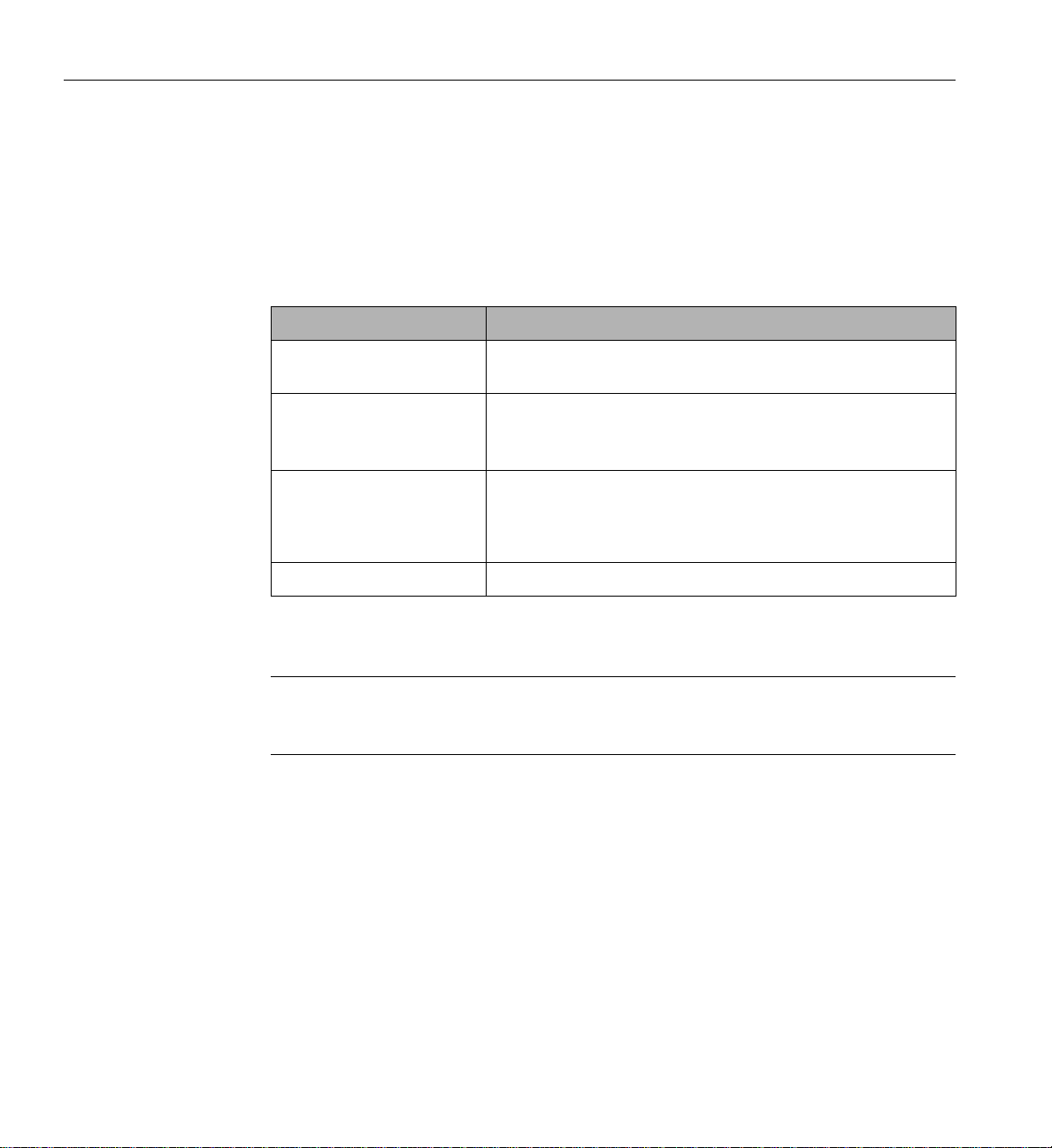
The following conventions are used throughout this document:
Convention Meaning
Command This fixed-space font denotes literal items such as commands, files,
routines, path names, signals, messages, and programming language
structures.
variable The italic typeface denotes variable entries and words or concepts being
defined. Italic typeface is also used for book titles.
user input This bold fixed-space font denotes literal items that the user enters in
interactive sessions. Output is shown in nonbold, fixed-space font.
[ ] Brackets enclose optional portions of a command or directive line.
... Ellipses indicate that a preceding element can be repeated.
man page(x) Man page section identifiers appear in parentheses after man page names.
GUI element This font denotes the names of graphical user interface (GUI) elements such
as windows, screens, dialog boxes, menus, toolbars, icons, buttons, boxes,
fields, and lists.
007-6419-002 xv

About This Guide
Product Support
Reader Comments
SGI provides a comprehensive product support and maintenance program for its products. SGI
also offers services to implement and integrate Linux applications in your environment.
• Refer to http://www.sgi.com/support/
• If you are in North America, contact the Technical Assistance Center at
+1 800 800 4SGI or contact your authorized service provider.
• If you are outside North America, contact the SGI subsidiary or authorized distributor in
your country.
If you have comments about the technical accuracy, content, or organization of this document,
contact SGI. Be sure to include the title and document number of the manual with your comments.
(Online, the document number is located in the front matter of the manual. In printed manuals, the
document number is located at the bottom of each page.)
You can contact SGI in any of the following ways:
• Send e-mail to the following address: techpubs@sgi.com
• Contact your customer service representative and ask that an incident be filed in the SGI
incident tracking system.
http://www.sgi.com/support/supportcenters.html
SGI values your comments and will respond to them promptly.
xvi 007-6419-002

Chapter 1
1. Introduction
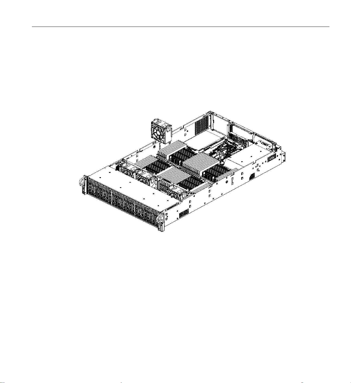
The SGI UV 30 server is a 2U rackmount server (see Figure 1-1). It has two main subsystems: the
2U server chassis and a quad-processor serverboard.
Figure 1-1 The SGI UV 30 Server
This chapter describes the server using the following topics:
• “Server Chassis Features” on page 2
• “Serverboard Features” on page 4
• “Additional Hardware Components” on page 6
See Appendix A, “Technical Specifications,” for the more details.
007-6419-002 1

1: Introduction
Server Chassis Features
Table 1-1 describes the main features of the SGI UV 30 server chassis.
Table 1-1 Server Chassis Features
Feature Description
System power The chassis features a redundant 2000W power supply consisting of two
Hard drives The chassis is designed to support twenty-four 2.5” hot-swappable hard
PCI expansion slots The system supports eleven PCIe
Control panel The front control panel, shown in Figure 1-2, provides system
hot-pluggable, Titanium-level power modules (96% efficiency). The
power redundancy allows the system to operate if one power supply
module fails or is replaced.
drive carriers. Twen ty bays are SAS3 and, depending on the connections
to the backplane, four hybrid bays support NVMe or SAS3.
®
3.0 expansion cards with four riser
cards. These include seven cards with external ports and four internal
cards. Two can be double-width GPUs.
monitoring and power control. LEDs indicate system power, HDD
activity, and network activity, UID (unit identifier), overheat, and fan
failure. A main power button and a reset button are also included.
Rear I/O ports As shown in Figure 1-3, the rear panel includes the following I/O ports:
– One VGA (monitor) port
– One COM port
– One dedicated IPMI LAN port
– Two USB 3.0 ports
Cooling system The chassis has an innovative cooling design that features four 8-cm fans
located in the middle section. Fan speed is determined by system
temperature as monitored by IPMI. Each power supply module also
includes a cooling fan.
The serverboard is fitted with an air shroud to maximize cooling.
2 007-6419-002

Server Chassis Features
Figure 1-2 shows the noteworthy components on the front of the server chassis.
Figure 1-2 Front Chassis View
Figure 1-3 shows the noteworthy components on the rear chassis panel.
Figure 1-3 Rear Chassis View
007-6419-002 3
1: Introduction
Serverboard Features
At the heart of the SGI UV 30 server is a quad-processor serverboard based on the Intel® C612
chipset, designed to provide maximum performance. Table 1-2 describes the major features of the
serverboard.
Table 1-2 Serverboard Features
Feature Description
Processors The serverboard supports up to four Intel
processors.
®
Xeon® E5-4600 v3 Series
Memory
Onboard serial ATA (SATA) A SATA controller is integrated into the chipset to provide a ten-port
Graphics controller There is integrated VGA with an ASPEED® AST2400 BMC.
The serverboard has 48 memory slots that can support up to 3 TB of
LRDIMM or 1.5 TB of RDIMM, DDR4-2133/1866/1600 memory.
SATA 3.0 subsystem. The I-SATA 4 and I-SATA 5 ports have built-in
power pins to support SuperDOMs (SATA disk-on-module solution).
RAID 0, 1, 5 and 10 are supported.
Figure 1-4 shows a block diagram of the serverboard.
Note: Figure 1-4 is a general block diagram and may not represent the exact features on your
serverboard. See Table 1-2 for the actual specifications of your serverboard. This block diagram
is intended for your reference only.
4 007-6419-002

Serverboard Features
Figure 1-4 Serverboard Block Diagram
007-6419-002 5

1: Introduction
Additional Hardware Components
In addition to the serverboard and chassis, the following hardware components have been included
with the server:
• Four conventional riser cards
• One Ultra riser card
• A plastic air shroud
• Four 8-cm system cooling fans
• Four passive CPU heat sinks
• One SAS backplane
• 24 hot-swap 2.5” HDD trays
• One rack rail set
Important: SGI servers may sometimes require driver versions that are not included in the
original operating system release. When required, SGI provides these drivers on the system disk
(pre-installed in the factory) or via portable media or download. For more information on this
topic, check with your sales or service representative.
6 007-6419-002

Chapter 2
2. System Safety
This chapter describes basic safety precautions.
Electrical Safety Precautions
Basic electrical safety precautions should be followed to protect yourself from harm and the SGI
UV 30 system from damage, as follows:
• Be aware of the locations of the power on/off switch on the chassis as well as the room's
emergency power-off switch, disconnection switch or electrical outlet. If an electrical
accident occurs, you can then quickly remove power from the system.
• Do not work alone when working with high voltage components.
• Power should always be disconnected from the system when removing or installing main
system components, such as memory modules and disk drives. When disconnecting power,
you should first power down the operating system first and then unplug the power cords. The
unit has more than one power supply cord. Disconnect two power supply cords before
servicing to avoid electrical shock .
• When working around exposed electrical circuits, another person who is familiar with the
power-off controls should be nearby to switch off the power if necessary.
• Use only one hand when working with powered-on electrical equipment. This is to avoid
making a complete circuit, which will cause electrical shock. Use extreme caution when
using metal tools, which can easily damage any electrical components or circuit boards they
come into contact with.
• Do not use mats designed to decrease static electrical discharge as protection from electrical
shock. Instead, use rubber mats that have been specifically designed as electrical insulators.
• The power supply power cords must include a grounding plug and must be plugged into
grounded electrical outlets.
007-6419-002 7

2: System Safety
!
Lithium battery
Battery holder
• Serverboard Battery
Caution: There is a danger of explosion if the onboard battery is installed upside down,
which will reverse its polarities (see Figure 2-1). This battery must be replaced only with the
same or an equivalent type recommended by the manufacturer. Dispose of used batteries
according to the manufacturer's instructions.
• Mainboard replaceable soldered-in fuses: Self-resetting PTC (Positive Temperature
Coefficient) fuses on the mainboard must be replaced by trained service technicians only.
The new fuse must be the same or equivalent as the one replaced. Contact technical support
for details and support.
8 007-6419-002
Figure 2-1 Installing the Onboard Battery

General Safety Precautions
Follow these rules to ensure general safety:
• Keep the area around the SGI UV 30 system clean and free of clutter.
• The system weighs approximately 52 lbs (23.6 kg.) when fully loaded. When lifting the
system, two people at either end should lift slowly with their feet spread out to distribute the
weight. Always keep your back straight and lift with your legs.
• Place the chassis top cover and any system components that have been removed away from
the system or on a table so that they won't accidentally be stepped on.
• While working on the system, do not wear loose clothing such as neckties and unbuttoned
shirt sleeves, which can come into contact with electrical circuits or be pulled into a cooling
fan.
• Remove any jewelry or metal objects from your body, which are excellent metal conductors
that can create short circuits and harm you if they come into contact with printed circuit
boards or areas where power is present.
• After accessing the inside of the system, close the system back up and secure it to the rack
unit with the retention screws after ensuring that all connections have been made.
General Safety Precautions
• Do not make improper use of server rack or rail equipment, as noted Figure 2-2.
Figure 2-2 Improper Use of Server Rack and Railing
007-6419-002 9

2: System Safety
!
ESD Precautions
Caution: Electrostatic discharge (ESD) is generated by two objects with different electrical
charges coming into contact with each other. An electrical discharge is created to neutralize this
difference. The discharge can damage electronic components and printed circuit boards.
The following measures are generally sufficient to neutralize this difference before contact is
made to protect your equipment from ESD:
• Use a grounded wrist strap designed to prevent static discharge.
• Keep all components and printed circuit boards (PCBs) in their antistatic bags until ready for
use.
• Touch a grounded metal object before removing the board from the antistatic bag.
• Do not let components or PCBs come into contact with your clothing, which may retain a
charge even if you are wearing a wrist strap.
• Handle a board by its edges only; do not touch its components, peripheral chips, memory
modules or contacts.
• When handling chips or modules, avoid touching their pins.
• Put the serverboard and peripherals back into their antistatic bags when not in use.
• For grounding purposes, make sure your computer chassis provides excellent conductivity
between the power supply, the case, the mounting fasteners and the serverboard.
Operating Precautions
The following are two noteworthy operating precautions:
• Ensure that the chassis cover is in place when the server is operating to ensure proper
cooling. Out-of-warranty damage to the system can occur if this practice is not strictly
followed.
• Please handle used batteries carefully. Do not damage the battery in any way. A damaged
battery may release hazardous materials into the environment. Do not discard a used battery
in the garbage or a public landfill. Please comply with the regulations set up by your local
hazardous waste management agency to dispose of your used battery properly.
10 007-6419-002

Chapter 3
3. Server Installation
This chapter provides a quick setup checklist to get the SGI UV 30 server operational.
Unpack the System
Inspect the shipping container used for the server and note if it was damaged in any way. If the
server shows damage, file a damage claim with the carrier who delivered it.
Decide on a suitable location for the rack that supports the weight, power requirements, and
environmental requirements of the server. It should be situated in a clean, dust-free environment
that is well ventilated. Avoid areas where heat, electrical noise, and electromagnetic fields are
generated. Place the server rack near a grounded power outlet. Refer to “Warnings and
Precautions” on page 12.
Prepare for Setup
The shipping container should include two sets of rail assemblies, two rail mounting brackets and
the mounting screws that you will use to install the system into a rack.
Read this section in its entirety before you begin the installation procedure.
007-6419-002 11

3: Server Installation
!
!
Choose a Setup Location
Follow these guidelines:
Caution: The equipment is intended for installation only in a restricted access location.
• This product is not suitable for use with visual display work place devices according to
Clause 2 of the German Ordinance for Work with Visual Display Units document.
• Leave enough clearance in front of the rack to enable you to open the front door completely
(~25 inches) and approximately 30 inches of clearance in the back of the rack to allow for
sufficient airflow and ease in servicing.
Warnings and Precautions
Rack Precautions
Warning: Failure to follow the following guidelines can result in serious injury or damage
to the equipment.
• The SGI UV 30 server weighs 52 lbs (23.6 kg). Always use proper lifting techniques when
your move the server. Always get the assistance of another qualified person when you install
the sever in a location above your shoulders.
• Extend the leveling jacks on the bottom of the rack to the floor with the full weight of the
rack resting on them.
• Attach stabilizers to the rack in single rack installations.
• Couple racks together in multiple rack installations.
• Be sure the rack is stable before extending a component from the rack.
• Extend only one component at a time. Extending two or more components simultaneously
may cause the rack to tip over.
12 007-6419-002

Server Precautions
• Review the electrical and general safety precautions in Chapter 2, “System Safety.”
• Determine the placement of each component in the rack before you install the rails.
• Install the heaviest server components in the bottom of the rack first, and then work up.
• Use a regulating uninterruptible power supply (UPS) to protect the server from power surges
and voltage spikes and to keep your system operating in case of a power failure.
• Allow the hot-pluggable SATA drives and power supply modules to cool before touching
them.
• Always keep the rack’s front door and all panels and components on the servers closed when
not servicing to maintain proper cooling.
Rack Mounting Considerations
Ambient Operating Temperature
If installed in a closed or multi-unit rack assembly, the ambient operating temperature of the rack
environment may be greater than the ambient temperature of the room. Therefore, consideration
should be given to installing the equipment in an environment compatible with the manufacturer’s
maximum rated ambient temperature (
Rack Mounting Considerations
35º C or 95º F).
Note: Certain processor or coprocessor configurations may require more stringent temperature
constraints. If this is true for your system, SGI will so notify you.
Reduced Airflow
Equipment should be mounted into a rack so that the amount of airflow required for safe operation
is not compromised.
Mechanical Loading
Equipment should be mounted into a rack so that a hazardous condition does not arise due to
uneven mechanical loading.
007-6419-002 13

3: Server Installation
Circuit Overloading
Consideration should be given to the connection of the equipment to the power supply circuitry
and the effect that any possible overloading of circuits might have on overcurrent protection and
power supply wiring. Appropriate consideration of equipment nameplate ratings should be used
when addressing this concern.
Reliable Ground
A reliable ground must be maintained at all times. To ensure this, the rack itself should be
grounded. Particular attention should be given to power supply connections other than the direct
connections to the branch circuit (for example, the use of power strips, and so on).
Install the System into a Rack
This section provides information on installing the server into a rack. If the system has already
been mounted into a rack, refer to “Check the Serverboard Setup” on page 20. There are a variety
of rack units on the market, which may mean the assembly procedure will differ slightly. You
should also refer to the installation instructions that came with the rack unit you are using.
Note: This rail will fit a rack between 26.5" and 36.4" deep.
Separate the Sections of the Rack Rails and Install Outer Rack Rails
The chassis package includes two rail assemblies in the rack mounting kit. Each assembly consists
of two sections: an inner fixed chassis rail that secures directly to the server chassis and an outer
fixed rack rail that secures directly to the rack itself.
Steps 1–4 describe how to separate the inner and outer rails:
1. Locate the rail assembly in the chassis packaging as shown in Figure 3-1.
2. Extend the rail assembly by pulling it outward.
3. Press the quick-release tab.
4. Separate the inner rail from the outer rail assembly as shown in Figure 3-1.
14 007-6419-002

Install the System into a Rack
1
2
3
4
Rail Assembly
Extending the Rails
QuickRelease T ab
Separating the
Inner Rail Extension
5
6
7
Figure 3-1 Separating and Installing the Rack Rails
Outer rails attach to the rack and hold the chassis in place. The outer rails for the chassis extend
between 30 inches and 33 inches.
Steps 5–8 describe how to install the outer rails to the rack (see Figure 3-1):
5. Secure the back end of the outer rail to the rack, using the screws provided.
007-6419-002 15

3: Server Installation
Install the Inner Rails
6. Press the button where the two outer rails are joined to retract the smaller outer rail.
7. Hang the hooks of the rails onto the rack holes and if desired, use screws to secure the front
of the outer rail onto the rack.
8. Repeat steps 5-7 for the remaining outer rail.
The inner rails are different for the left side and right side of the chassis and are so labeled.
Perform the following steps to install an inner rail as illustrated in Figure 3-2:
1. Place the inner rail on the appropriate side of the chassis.
Align the hooks of the chassis with the rail holes. Make sure the rail faces outward.
2. To secure the rail to the chassis, slide the rail toward the front of the chassis until the
quick-release bracket snaps into place.
3. Optionally, secure the rail to the chassis with screws as illustrated.
4. Repeat the prior steps for the other inner rail.
16 007-6419-002

Install the System into a Rack
Figure 3-2 Installing the Inner Rails
007-6419-002 17
3: Server Installation
!
Install the Server in a Rack
Warning: The SGI UV 30 server weighs 52 lbs (23.6 kg). Always use proper lifting
techniques when your move the server . Always get the assistance of another qualified person
when you install the sever in a location above your shoulders. Failure to do so may r esult in
serious personal injury or damage to the equipment.
You shoul d now have rails attached to both the server chassis and the rack unit. The next step is
to install the server into the rack (refer to Figure 3-3).
1. Extend the outer rails as shown in Figure 3-3.
2. Align the inner rails of the chassis with the outer rails on the rack.
3. Slide the inner rails into the outer rails, keeping the pressure even on both sides. When the
chassis has been pushed completely into the rack, it should click into the locked position.
4. Optional screws may be used to secure the to hold the front of the chassis to the rack.
18 007-6419-002

Install the System into a Rack
Figure 3-3 Installing the Server in a Rack
Note: The figure above is for illustration purposes. Always install servers to the rack in a
bottom-to-top fashion.
007-6419-002 19

3: Server Installation
Check the Serverboard Setup
After you install the server in the rack, you will need to open the unit to make sure the serverboard
is properly installed and all the connections have been made. Before operating the server for the
first time, it is important to remove any protective film covering the top of the chassis. The
removal of this film allows for proper ventilation and cooling.
Removing the Chassis Cover
Use the following procedure for removing the chassis cover as illustrated in Figure 3-4.
Note: Ensure that the system is not turned on or connected to AC power.
1. If the server is rack-mounted, grasp the two front handles and pull the server straight out
until it locks.
You will hear a click when it locks. T o remove the system from the rack completely, depress
the locking tabs on the chassis rails (push the right-side tab down and the left-side tab up) to
continue to pull the system out past the locked position.
2. If the two optional screws are securing the cover to the chassis, remove them, one from each
side of the cover.
3. Press both release tabs at the same time to unlock the cover and slide the cover to the rear.
4. Lift the cover from the chassis.
20 007-6419-002

Check the Serverboard Setup
Figure 3-4 Accessing the Inside of the Chassis
007-6419-002 21

3: Server Installation
Checking the Components and Setup
You may have two or four processors already installed in your serverboard. Ensure that the
serverboard is populated per your order.
Your server system comes with system memory already installed. Make sure all DIMMs are fully
seated in their slots.
Ensure that all power and data cables are properly connected and not blocking the chassis airflow.
Also, make sure that no cables are positioned in front of the fans.
Checking the Drive Bay Setup
Ensure that the peripheral drives and the disk drives have been properly installed and all
connections have been made.
Do not operate the server without drives or drive trays in the drive bays. Depending upon your
system’s configuration, your system may have one or more drives already installed. All drives are
accessible from the front of the server. If you need to install hard drives, see “Replacing Disk
Drives” on page 34. Use only recommended server parts.
Checking the Airflow
Airflow is provided by four 8-cm chassis cooling fans. The system component layout was
carefully designed to direct sufficient cooling airflow to the components that generate the most
heat.
Ensure that all power and data cables have been routed in such a way that they do not block the
airflow generated by the fans.
Providing Power
Plug the power cord(s) from the power supply unit(s) into a high-quality power strip that offers
protection from electrical noise and power surges. It is recommended that you use an
uninterruptible power supply (UPS).
Depress the power button on the control panel, located on the front of the chassis. See “Control
Panel Components” on page 24.
22 007-6419-002

Chapter 4
4. System Monitoring
There are several buttons and LEDs on the control panel, drive carriers, and power supplies to
keep you constantly informed of the overall status of the system. As shown in Figure 4-1, the
control panel is on the left handle of the chassis.
Figure 4-1 Front Control Panel
This chapter describes the functions of the buttons and LEDs and the appropriate responses you
may need to take.
007-6419-002 23

4: System Monitoring
Control Panel Components
Figure 4-2 shows the components of the control panel.
A
E
F
G
Figure 4-2 Control Panel Components
B
C
D
24 007-6419-002

Control Panel Components
Table 4-1 describes the functions of the components.
Table 4-1 Control Panel Components
Component Descriptio n
A The main power button is used to apply or remove power from the power supply
to the server. T urning of f system power with this button removes the main power
but keeps standby power supplied to the system. Therefore, you must unplug the
server before servicing.
RESET Depressing this button resets all registers and reboots the operating system.
B When flashing, this LED indicates HDD activity.
C, F When flashing, these LEDs indicates network activity on the GLAN1 and
GLAN2, respectively.
D This is the Universal Information LED. It can indicate an overheat condition, fan
failure, power failure, or the UID button activation. See Table 4-2.
This LED will remain solid red or continue to flash as long as the temperature is
too high or a fan does not function properly.
E When illuminated, this LED indicates that power is being supplied by the power
supply units. This LED should be illuminated when the system is operating.
G When illumin ated, this LED indicates a power failure.
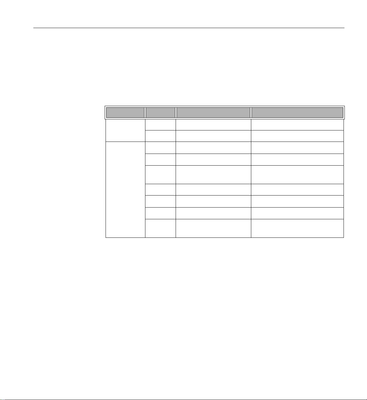
Table 4-2 Universal Information LED States
LED State Condition
Blinking red (1 Hz) Fan failure
Blinking red (0.25 Hz) Power failure. Check the power supplies.
007-6419-002 25

4: System Monitoring
Table 4-2 Universal Information LED States (continued)
LED State Condition
Solid red An overheat condition has occurred.
For an overheat condition, consider the following:
- Ensure that the ambient room temperature is not too warm.
- Check the routing of cables and make sure all fans are present and
operating.
- Ensure that the chassis cover and air shrouds are installed.
- Verify that the heatsinks are installed properly.
Solid blue Local UID button depressed. Use this function to locate the server
in a rack.
Blinking blue IPMI-activated UID. Use this function to identif
y the server from a remote location.
26 007-6419-002
Drive Carrier LEDs
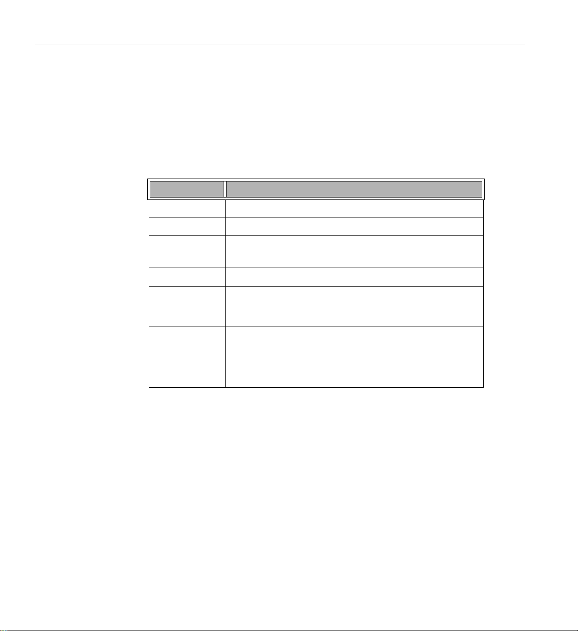
Drive Carrier LEDs
Each hard drive carrier has two LEDs. Table 4-3 describes the functions of the two LEDs.
Table 4-3 Drive Carrier LEDs
LED Color Blinking Pattern Behavior for Device
Activity LED Blue Solid on SAS/NVMe drive installed
Blue Blinking I/O activity
Status LED Red Solid on Failure of drive with RSTe support
Red Blinking at 1 Hz Rebuild drive with RSTe support
Red Blinking with two blinks and
one stop at 1 Hz
Red On for five seconds, then off Power on for drive with RSTe support
Red Blinking at 4 Hz Identify drive with RSTe sup port
Green Solid on Safe to remove NVMe device
Amber Blinking at 1 Hz Attention state. Do not remove NVMe
Hot spare for drive with RSTe support
device.
Refer to “Replacing Disk Drives” on page 34 for instructions on replacing failed drives.
007-6419-002 27
4: System Monitoring
Power Supply LED
There is a single bi-color LED (green/amber) to indicate the power supply status. Table 4-4
describes the different states of the LED.
Table 4-4 Power Supply LED States
LED State Power Supply (PS) State
Off No AC power to any PS.
Green Output on and Ok.
Green, 1Hz blink AC present (only 12VSB on). PS off or PS in cold redundant state.
Note: This is the normal state for a redundant PS.
Green, 2Hz blink PS firmware updating.
Amber – PS critical event causing a shutdown/failure (OCP, OVP, fa n fail ure)
– AC cord unplugged or AC power lost. A second power supply in
parallel still has AC input power.
Amber, 1Hz blink PS warning events where the power supply continues to operate (high
temperature, high power, high current, slow fan). The system power
supply temperature has reached 63
power-down when the power supply temperature reaches 70ºC and
restart when the power supply temperature goes below 60
28 007-6419-002
ºC. The system will automatically
ºC.

Chapter 5
5. Chassis Maintenance
For warranty and safety considerations, SGI designates the following chassis components as
customer-replaceable units:
• Power supplies
•Fans
• Disk drives
The disk drives and power supplies are hot-swappable; that is, you can replace them without
powering down the server. As a safety precaution, replacing the fans requires a system
power-down. A trained service technician should install and replace all other components.
This chapter describes the following chassis maintenance activities:
• “Removing the Chassis Cover” on page 30
• “Replacing a Power Supply” on page 32
• “Replacing Disk Drives” on page 34
• “Replacing System Fans” on page 38
007-6419-002 29

5: Chassis Maintenance
!
Before You Start
Warning: Review the warnings and pr ecautions listed in this manual befor e setting up or
servicing this chassis. These include the items described in Chapter 2, “System Safety.”
Tools and Supplies Needed
• Phillips (cross head) screwdriver
• Anti-static wrist strap and conductive foam pad (recommended)
Left-Right and User Position
All references to left, right, front, top, and bottom assume you are facing the front of the chassis
as it would be positioned for normal operation.
Removing the Chassis Cover
Caution: Except for short periods of time, do not operate the server without the cover in place.
The chassis cover must be in place to allow proper airflow and prevent overheating.
Use the following procedure for removing the chassis cover as illustrated in Figure 5-1.
Note: Ensure that the system is not turned on or connected to AC power.
1. If the server is rack-mounted, grasp the two front handles and pull the server straight out
until it locks.
You will hear a click when it locks. T o remove the system from the rack completely, depress
the locking tabs on the chassis rails (push the right-side tab down and the left-side tab up) to
continue to pull the system out past the locked position.
2. If the two optional screws are securing the cover to the chassis, remove them, one from each
side of the cover.
30 007-6419-002

Removing the Chassis Cover
3. Press both release tabs at the same time to unlock the cover and slide the cover to the rear.
4. Lift the cover from the chassis.
Figure 5-1 Accessing the Inside of the Chassis
007-6419-002 31

5: Chassis Maintenance
!
Replacing a Power Supply
The server chassis includes a redundant, hot-pluggable 2000W power supply, consisting of two
power modules. They have an auto-switching capability, which enables them to automatically
sense and operate at a 100V–240V input voltage.
If either of the two power supply modules fail, the other module will take the full load and allow
the system to continue operation without interruption. The power fail LED will illumin ate and
remain on until the failed unit has been replaced.
Use the following steps to replace a power supply.
Caution: Unplug the AC power cord from the failed power supply module to reduce the risk
of injury from electric shock.
1. Pull out the power supply handle and press the retaining clip on the right side of the
power supply, as illustrated in Figure 5-2.
2. While pressing the retaining clip, pull the power supply out. See Figure 5-3.
3. Push the new power supply module into the power bay until you hear a click.
4. Plug the AC power cord back into the module.
Figure 5-2 Power Supply Release Tab
32 007-6419-002

Replacing a Power Supply
Figure 5-3 Replacing a Power Supply
007-6419-002 33

5: Chassis Maintenance
Replacing Disk Drives
Caution: Except for short periods of time while swapping hard drives, do not operate the s erver
with the hard drive slots empty.
The server has twenty-four hot-swappable 2.5" drive bays. The hard drives are mounted in drive
carriers to simplify their installation and removal from the chassis. System power may remain on
when removing carriers with drives installed. These carriers also help promote proper airflow for
the drive bays. For this reason, even empty carriers without drives installed must remain in the
chassis.
Removing Carrier from Chassis and Drive from Carrier
Use the following procedure to remove the HDD carrier from the chassis and the drive from the
carrier.
1. Press the release button on the drive carrier.
This extends the drive carrier handle. See Figure 5-4.
2. Using the handle, pull the drive carrier out of the chassis.
3. Remove the disk drive or dummy drive from the carrier.
See Figure 5-5.
34 007-6419-002

Replacing Disk Drives
Figure 5-4 Removing HDD Carrier from Chassis
007-6419-002 35

5: Chassis Maintenance
Figure 5-5 Removing Dummy Drive from Carrier
36 007-6419-002

Installing a Drive into a Carrier
Use the following procedure to install a drive into a carrier.
1. Install a new drive into the carrier with the printed circuit board side facing down so that the
mounting holes in the drive align with those in the carrier.
See Figure 5-6.
2. Secure the hard drive into the carrier with four screws.
3. Use the open handle to replace the drive carrier into the chassis.
4. Gently close the drive carrier handle to secure the drive and carrier into the chassis drive bay.
Replacing Disk Drives
Figure 5-6 Installing a Drive into a Carrier
007-6419-002 37

5: Chassis Maintenance
Replacing System Fans
Fan speed is controlled by system temperature via IPMI. If a fan fail s, the remaining fan will ramp
up to full speed and the overheat/fan fail LED on the control panel will turn on. Replace any failed
fan at your earliest convenience with the same type and model. The system can continue to run
with a failed fan.
Use the following procedure to replace a failed fan:
1. Remove the top chassis cover while the system is still running to determine which of the
fans has failed.
See “Removing the Chassis Cover” on page 30.
2. Power down the system.
3. Remove the power cord(s) as a safety precaution.
4. Unplug the fan wiring from the serverboard and remove the failed fan.
5. Press the fan release tab to lift the failed fan from the chassis and pull it completely from the
chassis.
See Figure 5-7.
6. Place the new fan into the vacant space in the housing while making sure the arrows on the
top of the fan (indicating air direction) point in the same direction as the arrows on the other
fans.
7. Power up the system and ensure that the fan is working properly before replacing the chassis
cover.
38 007-6419-002
Replacing System Fans
Figure 5-7 System Fans
007-6419-002 39


Chapter 6
6. Tr oubleshooting
This chapter describes troubleshooting for the problems listed below. Chapter 4 describes use of
the control panel to monitor the overall system status and the status of specific components.
Chapter 5, “Chassis Maintenance” describes how to replace defective components.
• “If the System Does Not Power Up” on page 42
• “System Powers Up But Will Not Boot” on page 42
• “No Video After System Power Up” on page 43
• “Perceived Boot Freezes (GPU Configurations)” on page 43
• “Memory Errors” on page 44
If you follow all of the prescribed procedures and still need assistance, check with your authorized
support organization.
007-6419-002 41

6: Troubleshooting
If the System Does Not Power Up
If the system will not power up when the front power button is pushed, use the following checklist
to identify common sources for the problem:
• Make sure that both ends of each system power cable are firmly connected to the power
supply and the corresponding power source(s) or power distribution unit (PDU).
• Check that the LED on each power supply is properly lit. The power supply has one status
LED located on the left side of the front of the power supply . The status LED has three states
as follows:
– Dark or off—Indicates no AC power present.
– Yellow—AC power is present. The server is not turned on (no DC power).
– Flashes slowly (about four seconds on/off)—Power supply has failed.
– Green—AC power is present and the server is turned on (DC power present).
• Open the system cover, remove the air shroud, and check to make sure that no obvious short
circuits exist between the serverboard and chassis.
If you must replace the power supply, refer to “Replacing a Power Supply” on page 32.
System Powers Up But Will Not Boot
If the system powers up but will not boot the operating system, check the following:
• Check the system order document(s) - the server may have been ordered with no operating
system. If so, check with your system administrator for OS loading information.
• Check the system disk for drive activity and confirm that it is firmly seated in the disk bay. A
red light on the front of the disk indicates a functional error. Check with your service
provider or local system administrator.
42 007-6419-002

No Video After System Power Up
If the system powers up and appears to be booting normally but no video is present, try the
following basic solutions:
• Confirm your monitor is plugged in and switched on.
• Check all video cables and ensure they are properly connected.
• If using an optional PCIe video card, check the back of the card for LED activity or a fault
indicator. Try opening the system, reseating the PCI card, and rebooting.
If you cannot get a video signal after trying the basic solutions, contact your support provider.
Perceived Boot Freezes (GPU Configurations)
When GPUs have been configured in your system, the boot process may appear to freeze after the
POST code 91 or A9 stage. Most likely, the boot process does, in fact, proceed but the video output
switches from the default onboard video port to that of the offboard GPUs once the GPUs have
been initialized. This behavior is the expected behavior when offboard video has been designated
as the the primary video port. The setting for VGA Priority in BIOS determines this primacy.
More generally, the keyboard, mouse, and video capabilities are affected.
No Video After System Power Up
In the event where offboard video has been designated as the the primary video port and there is
no addin GPU configured, you will lose video on reboots. In this case, you must configure an
addin GPU or clear CMOS to reclaim video on reboots.
007-6419-002 43

6: Troubleshooting
Memory Errors
If your system experiences memory related errors, try these basic troubleshooting steps to resolve
or better identify the problem:
• Confirm that the power supply LED is not indicating an error.
• Shut the system down, remove the covers over the serverboard and make sure that all the
DIMM modules are properly and fully installed.
• You should be using registered ECC DDR4 mem ory. Also, it is recommended that you use
the same memory type and speed for all DIMMs in the system.
• Check for bad DIMM modules or slots by swapping modules between slots and noting the
results.
Contact your administrator or support provider if the memory errors continue.
44 007-6419-002

Appendix A
A. Technical Specifications
Table A-1 lists allowable ranges for temperature, humidity, and altitude for the SGI UV 30 server.
Table A-1 Temperature, Humidity, and Altitude Specifications
Attribute Specification Rate of Change Constraints
While Product Operating
Temperature – Up to 1500m (5000ft)
ºC (41ºF) to +35ºC
+5
– 1525m (5000ft) to 3050m (10,000ft)
Reduce max temperature (35
305m (1000ft) of altitude above 1525m
(5000ft).
Humidity 20% to 80% Non-condensing Maximum: 10% relative
Altitude 3050m (10,000ft)
While Product Power Off
Temperature +5
Humidity 8% to 80% Non-condensing
Altitude 3050m (10,000ft)
While Product Packaged for Shipping
Temperature -40
Humidity 8% to 80% Non-condensing
Altitude 12,200m (40,000ft)
Notes:
1. Certain processor or coprocessor configurations may require more stringent temperature constraints–for
example, a maximum ambient temperature of 25 ºC or 30ºC. If this is true for your system, SGI will so
notify you.
ºC (41ºF) to +45ºC (113ºF) Maximum: 20ºC/hour (36ºF/hour)
ºC (-40ºF) to +60ºC (140ºF) Maximum: 20ºC/hour (36ºF/hour)
1
(95ºF)
1
ºC
) by 1ºC per
Maximum: 10
humidity/hour
ºC/hour (18ºF/hour)
007-6419-002 45

A: Technical Specifications
Table A-2 lists other key specifications for the server.
Table A-2 Miscellaneous System Specifications
Attribute Specification
Processors
– Up to four Intel Xeon E5-4600 v3 Series processors
– LGA2011 sockets (Socket R3)
Chipset Intel PCH C612 chipset
®
BIOS 16 MB AMI
SPI Flash EEPROM
Memory 3 TB of LRDIMM (or 1.5 TB RDIMM) DDR4 2133/1866/1600 memory
SATA Controller Intel chipset-based co ntroller provides support for 10 SATA 3.0 ports (RAID
0, 1, 5, and 10 supported)
Drive Bays – 24 hot-swap drive bays to house standard 2.5” drives
– One 5.25” drive day
PCI Expansion
Slots
– Two PCIe
– Two PCIe 3.0 x8 cards (full-height, full-length)
– Two PCIe
®
3.0 x16 cards (full-height, full-length)
3.0 x8 cards (full-height, half-length)
– One PCIe 3.0 x8 card (low-profile, half-length)
– Four PCIe 3.0 x8 cards (low-profile, internal)
Onboard Graphics ASPEED
®
AST2400 BMC chip
Chassis 2U standard-depth rackmount
Dimensions: (WxHxD) 19 x 3.2 x 35.9 in. (48.3 x 8.2 x 91.2 cm)
(Includes handles and power supply extension.)
Serverboard Dimensions: (LxW) 20 x 16.8 in. (50.8 x 42.7 cm)
W e ight Gross: 52 lbs (23.6 kg)
System Cooling Four 8-cm high-performance fans
System Input
Requirements
– AC Input Voltage: 100 – 240V AC auto-range
– Rated Input Current: 13 – 4A max
– Rated Input Frequency: 50 – 60 Hz
46 007-6419-002
Table A-2 Miscellaneous System Specifications (continued)
Attribute Specification
Power Supply
Regulatory
Compliance
– 2 x Hot-pluggable 1U PSU 2000W
– Rated Output Power: 2000W redundant power
– Rated Output Voltages: +12V (62.5A at 100–127VAC, 83A at
200–240VAC), +12Vsb (2.1A)
Electromagnetic Emissions: FCC Class A, EN 55022 Class A, EN
61000-3-2/-3-3, CISPR 22 Class A
Electromagnetic Immunity: EN 55024/CISPR 24, (EN 61000-4-2, EN
61000-4-3, EN 61000-4-4, EN 61000-4-5, EN 61000-4-6, EN 61000-4-8, EN
61000-4-11)
Safety: CSA/EN/IEC/UL 60950-1 Compliant, UL or CSA Listed (USA and
Canada), CE Marking (Europe)
California Best Management Practices Regulations for Perchlorate Materials:
“This Perchlorate warning applies only to products containing CR (Manganese
Dioxide) Lithium coin cells. Special handling for perchlorate material may
apply. See the webpage www.dtsc.ca.gov/hazardouswaste/perchlorate.”
007-6419-002 47

Appendix B
B. BIOS Error Codes
During Power-On Self-Test (POST) routines, which are performed each time the system is
powered on, errors may occur.
Non-fatal errors are those which, in most cases, allow the system to continue the boot-up process.
The error messages normally appear on the screen.
Fatal errors are those which will not allow the system to continue the boot-up procedure. If a fatal
error occurs, you should consult with SGI for possible repairs.
These fatal errors are usually communicated through a series of audible beeps. The numbers on
the fatal error list correspond to the number of beeps for the corresponding error.
Table B-1 BIOS Error Codes
Beep Code Error Message Description
1 beep Refresh Circuits have been reset. Ready to power up.
5 short beeps + 1 long beep Memory error No memory detected in the system
5 long beeps + 2 long beeps Display memory read/write
error
1 continuous beep System OH System overheat
007-6419-002 49
Video adapter missing or with faulty
memory

 Loading...