

Page 1

SGI® Total Performance 900
Storage System User’s Guide
007-4428-003
Page 2

CONTRIBUTORS
Written by Olivier Clarinval, updated by Steven Levine
Illustrated by Dan Young and Chrystie Danzer
Production by Karen Jacobson
Engineering contributions byWendy Nunn, Glenn Stettler, and P. Van Tran.
COPYRIGHT
© 2001-2004 Silicon Graphics, Inc. All rights reserved; provided portions may be copyright in third parties, as indicated elsewhere herein. No
permission is granted to copy, distribute, or create derivative works from the contents of this electronic documentation in any manner, in whole
or in part, without the prior written permission of Silicon Graphics, Inc.
LIMITED RIGHTS LEGEND
The software described in this document is “commercial computer software” provided with restricted rights (except as to included open/free
source) as specified in the FAR 52.227-19 and/or the DFAR 227.7202, or successive sections. Use beyond license provisions is a violation of
worldwide intellectual property laws, treaties and conventions. This document is provided with limited rights as defined in 52.227-14..
TRADEMARKS AND ATTRIBUTIONS
Silicon Graphics is a registered trademark, and SGI, the SGI logo, and IRIS InSight are trademarks of Silicon Graphics, Inc., in the United States
and/or other countries worldwide.
For regulatory information, see Appendix B.
Page 3

Record of Revision
Version Description
001 August 2001
Initial Revision
002 February 2004
Revision to support TP900 U320 release
003 May 2004
Firmware upgrade procedure removed
007-4428-003 iii
Page 4

Page 5

Contents
Contents
Figures . . . . . . . . . . . . . . . . . . . . . . . . . . ix
Tables . . . . . . . . . . . . . . . . . . . . . . . . . . xi
About This Guide. . . . . . . . . . . . . . . . . . . . . . .xiii
Audience . . . . . . . . . . . . . . . . . . . . . . . . . xiv
Related Publications . . . . . . . . . . . . . . . . . . . . . . xiv
Product Support . . . . . . . . . . . . . . . . . . . . . . . xiv
Reader Comments . . . . . . . . . . . . . . . . . . . . . . . xiv
1. Storage System Features . . . . . . . . . . . . . . . . . . . . . 1
Enclosure Chassis . . . . . . . . . . . . . . . . . . . . . . . 2
Front Panel LEDs . . . . . . . . . . . . . . . . . . . . . . . 4
Plug-in Modules . . . . . . . . . . . . . . . . . . . . . . . 5
Drive Carrier Modules . . . . . . . . . . . . . . . . . . . . 6
Power Supply Module . . . . . . . . . . . . . . . . . . . . 10
Input/Output (I/O) Module . . . . . . . . . . . . . . . . . . 12
Cooling Module . . . . . . . . . . . . . . . . . . . . . . 14
Dummy Carrier Modules . . . . . . . . . . . . . . . . . . . 16
Blank Modules . . . . . . . . . . . . . . . . . . . . . . 16
Storage System Bay Numbering Convention . . . . . . . . . . . . . . . 17
2. Setup and Operation . . . . . . . . . . . . . . . . . . . . . .19
Unpacking and Inspecting the Storage System. . . . . . . . . . . . . . .19
Connecting the Power Cord . . . . . . . . . . . . . . . . . . . . 20
Attaching Interface Cables . . . . . . . . . . . . . . . . . . . . 21
1 x 8 Configuration . . . . . . . . . . . . . . . . . . . . . 21
2 x 4 Configuration . . . . . . . . . . . . . . . . . . . . . 23
007-4428-003 v
Page 6

Contents
SCSI_ID Addressing . . . . . . . . . . . . . . . . . . . . . . 24
1x 8 Configuration. . . . . . . . . . . . . . . . . . . . . . 24
2 x 4 Configuration . . . . . . . . . . . . . . . . . . . . . 25
Powering On the Enclosure . . . . . . . . . . . . . . . . . . . . 26
Powering Off the Enclosure . . . . . . . . . . . . . . . . . . . . 27
Engaging the Anti-tamper Locks . . . . . . . . . . . . . . . . . . . 28
3. Replacing Modules . . . . . . . . . . . . . . . . . . . . . . 31
Pre-installation Safety Precautions . . . . . . . . . . . . . . . . . . 32
Dealing with Hardware Faults . . . . . . . . . . . . . . . . . . . 32
Continuous Operation during Replacement . . . . . . . . . . . . . . .32
Replacing Power Supply Modules . . . . . . . . . . . . . . . . . . 33
Replacing Cooling Modules . . . . . . . . . . . . . . . . . . . . 35
Replacing I/O Modules . . . . . . . . . . . . . . . . . . . . . 36
Replacing Drive Carrier Modules . . . . . . . . . . . . . . . . . . 37
Component Part Numbers . . . . . . . . . . . . . . . . . . . . 40
4. Troubleshooting . . . . . . . . . . . . . . . . . . . . . . . 41
Overview . . . . . . . . . . . . . . . . . . . . . . . . . 42
Initial Startup Problems . . . . . . . . . . . . . . . . . . . . . 44
System Faults . . . . . . . . . . . . . . . . . . . . . . . . 45
Power Supply Faults . . . . . . . . . . . . . . . . . . . . . . 45
Cooling Module Faults. . . . . . . . . . . . . . . . . . . . . . 46
A. Technical Specifications . . . . . . . . . . . . . . . . . . . . . 47
Physical and Environmental Specifications . . . . . . . . . . . . . . . . 48
Power Requirements . . . . . . . . . . . . . . . . . . . . . . 49
B. Regulatory Information . . . . . . . . . . . . . . . . . . . . . 51
Manufacturer’s Declaration of Conformity . . . . . . . . . . . . . . . . 51
FCC Class B Conformance. . . . . . . . . . . . . . . . . . . . . 52
Industry Canada Notice (Canada Only) . . . . . . . . . . . . . . . . . 52
CE Notice . . . . . . . . . . . . . . . . . . . . . . . . . 53
VCCI Notice (Japan Only) . . . . . . . . . . . . . . . . . . . . . 53
Korean Regulatory Notice . . . . . . . . . . . . . . . . . . . . . 53
Shielded Cables. . . . . . . . . . . . . . . . . . . . . . . . 54
vi 007-4428-003
Page 7

Contents
Electrostatic Discharge . . . . . . . . . . . . . . . . . . . . . 54
Electromagnetic Emissions . . . . . . . . . . . . . . . . . . . . 54
Index . . . . . . . . . . . . . . . . . . . . . . . . . . 55
007-4428-003 vii
Page 8

Page 9

Figures
Figures
Figure 1-1 Front View of an SGI TP900 Storage System . . . . . . . 2
Figure 1-2 Rear Module Location in Standard Configuration . . . . . . 2
Figure 1-3 Rear Module Location in Redundant Configuration . . . . . 3
Figure 1-4 ESI/Ops Panel . . . . . . . . . . . . . . . . 4
Figure 1-5 Drive Carrier Module . . . . . . . . . . . . . . 6
Figure 1-6 Drive Carrier LED Indicators . . . . . . . . . . . . 7
Figure 1-7 Anti-tamper Locks . . . . . . . . . . . . . . . 8
Figure 1-8 Drive Information Label . . . . . . . . . . . . . 9
Figure 1-9 Power Supply Module . . . . . . . . . . . . . . 10
Figure 1-10 Power Supply Indicators . . . . . . . . . . . . . 11
Figure 1-11 Ultra-3 SCSI I/O Module . . . . . . . . . . . . . 12
Figure 1-12 I/O Modules in 1 x 8 Configuration . . . . . . . . . . 13
Figure 1-13 1 x 8 configuration U160/U320 Loopback Module . . . . . . 13
Figure 1-14 1 x 8 configuration U160 Loopback Module. . . . . . . . 14
Figure 1-15 Cooling Module . . . . . . . . . . . . . . . 15
Figure 1-16 Drive Bay Numbering . . . . . . . . . . . . . . 17
Figure 1-17 Rear Module Locations and Bay Numbering . . . . . . . 18
Figure 2-1 Attaching Interface Cable on 1 x 8 Configuration . . . . . . 22
Figure 2-2 Attaching Interface Cable on 2 x 4 Configuration . . . . . . 23
Figure 2-3 1 x 8 SCSI_ID Addressing . . . . . . . . . . . . . 24
Figure 2-4 2 x 4 SCSI_ID Addressing . . . . . . . . . . . . . 25
Figure 2-5 Activating an Anti-tamper Lock . . . . . . . . . . . 28
Figure 3-1 Power Supply Module Retaining Bracket . . . . . . . . 33
Figure 3-2 Power Supply Latch and Handle . . . . . . . . . . . 34
Figure 3-3 Cooling Module Retaining Bracket . . . . . . . . . . 35
007-4428-003 ix
Page 10

Figures
Figure 3-4 I/O Module Retaining Bracket . . . . . . . . . . . 36
Figure 3-5 Releasing the Carrier Handle . . . . . . . . . . . . 38
Figure 3-6 Carrier Camming Lever . . . . . . . . . . . . . 39
Figure 4-1 ESI/Ops Panel LEDs . . . . . . . . . . . . . . 42
x 007-4428-003
Page 11

Tables
Tables
Table 1-1 ESI/Ops LED States . . . . . . . . . . . . . . 4
Table 2-1 Supported cables . . . . . . . . . . . . . . . 21
Table 2-2 Drive enclosure device addressing . . . . . . . . . . 25
Table 2-3 Drive enclosure device addressing . . . . . . . . . . 26
Table 3-1 Component Part Numbers . . . . . . . . . . . . 40
Table 4-1 ESI/Ops LED States . . . . . . . . . . . . . . 43
Table 4-2 System Faults . . . . . . . . . . . . . . . . 45
Table 4-3 Power Supply Faults . . . . . . . . . . . . . . 45
Table 4-4 Cooling Module Faults. . . . . . . . . . . . . . 46
Table A-1 Physical and Environmental Specifications . . . . . . . . 48
Table A-2 Minimum Power Requirements . . . . . . . . . . . 49
007-4428-003 xi
Page 12

Page 13

About This Guide
This guide explains how to operate and maintain the SGI Total Performance (TP) 900
SCSI storage system in the following chapters:
• Chapter 1, “Storage System Features”
• Chapter 2, “Setup and Operation”
• Chapter 3, “Replacing Modules”
• Chapter 4, “Troubleshooting”
• Appendix A, “Technical Specifications”
• Appendix B, “Regulatory Information”
An index completes this guide.
007-4428-003 xiii
Page 14

About This Guide
Audience
This guide is written for owners and users of the SGI TP900 SCSI storage system. It
presumes general knowledge of SCSI technology and knowledge of the host SGI server,
the HBA, and other SCSI devices to which the storage system might be cabled.
Related Publications
Besides this manual and the manuals for the storage system third-party software, you
should locate the latest versions of the user’s guide for the servers. If you do not have
these guides, you can find the information online in the following locations:
• IRIS InSight Library. From the Toolchest, select Help > Online Books >
• Technical Publications Library. If you have access to the Internet, see the following
SGI EndUser or SGI Admin, and select the applicable owner’s or hardware guide.
URL:
http://techpubs.sgi.com/library/
Product Support
SGI provides a comprehensive product support and maintenance program for its
products:
• If you are in North America and want support for your SGI-supported products,
contact the Technical Assistance Center at 1-800-800-4SGI or your authorized
service provider.
• If you are outside North America, contact the SGI subsidiary or authorized
distributor in your country.
Reader Comments
If you have comments about the technical accuracy, content, or organization of this
document, contact SGI. Be sure to include the title and document number of the manual
with your comments. (Online, the document number is located in the front matter section
xiv 007-4428-003
Page 15

About This Guide
of the manual. In printed manuals, the document number is located at the bottom of each
page.)
You can contact SGI in any of the following ways:
• Send e-mail to the following address:
• Use the Feedback option on the Technical Publications Library Web page:
http://docs.sgi.com
• Contact your customer service representative and ask that an incident be filed in the
SGI incident tracking system.
• Send mail to the following address:
Technical Publications
SGI
1500 Crittenden Lane
Mountain View, California 94043-1351
SGI values your comments and will respond to them promptly.
007-4428-003 xv
Page 16

Page 17

Chapter 1
1. Storage System Features
The SGI TP900 is a 2U-high 8-drive storage system that provides compact, high-capacity,
high-availability JBOD (“just a bunch of disks”) storage for supported SGI servers. The
enclosure backplane connects the 8 drives on one SCSI bus. As an option, the storage
system can also be configured on two SCSI busses (two strings of 4 drives). The SGI
TP900 is rack-mountable and is designed to use SCSI Parallel Interface 3 (SPI-3) capable
Low Profile (1-inch high) 3.5-inch disk drives. The drive carriers accept SGI-qualified
10,000 or 15,000 rpm U160/U320 SCSI disk drives.
This chapter gives information on the basic features of the SGI TP900 SCSI storage
system in the following sections:
• “Enclosure Chassis” on page 2
• “Front Panel LEDs” on page 4
• “Plug-in Modules” on page 5
• “Storage System Bay Numbering Convention” on page 17
007-4428-003 1
Page 18
1: Storage System Features
Enclosure Chassis
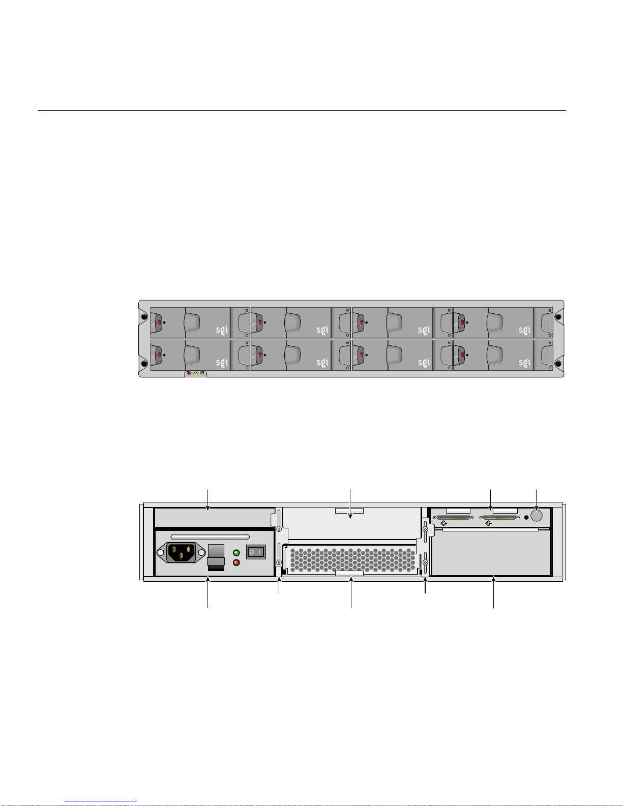
The basic unit of the SGI TP900 storage system is the enclosure, which contains the disk
drives arranged in two rows of 4 drives, and the drive backplane in the front. The I/O,
power supply (PSU), and fan modules are located at the rear of the chassis. The chassis
uses two EIA units of rack space, and is fitted with 19-inch rack-mounting features,
which enable it to be mounted into standard 19-inch racks.
Figure 1-1 shows the front of the enclosure, with the full complement of 8 disk drive
modules.
Figure 1-1 Front View of an SGI TP900 Storage System
Figure 1-2 shows the back of an enclosure, which contains one of each of the following:
cooling module, cooling blank module, PSU module, PSU blank module, I/O module,
and I/O loopback module.
Cooling blank module
OUTPUT
GOOD
FAULT
Retaining bracket Retaining bracket
PSU
Cooling module
Figure 1-2 Rear Module Location in Standard Configuration
2 007-4428-003
I/O moduleI/O loopback module
CHANNEL 2 CHANNEL 1
PSU blank module
ID range
Page 19
Enclosure Chassis
Blank modules occupy unoccupied empty bays and must be in place for proper
operation and to ensure correct airflow. The component modules are discussed in detail
in “Plug-in Modules” on page 5.
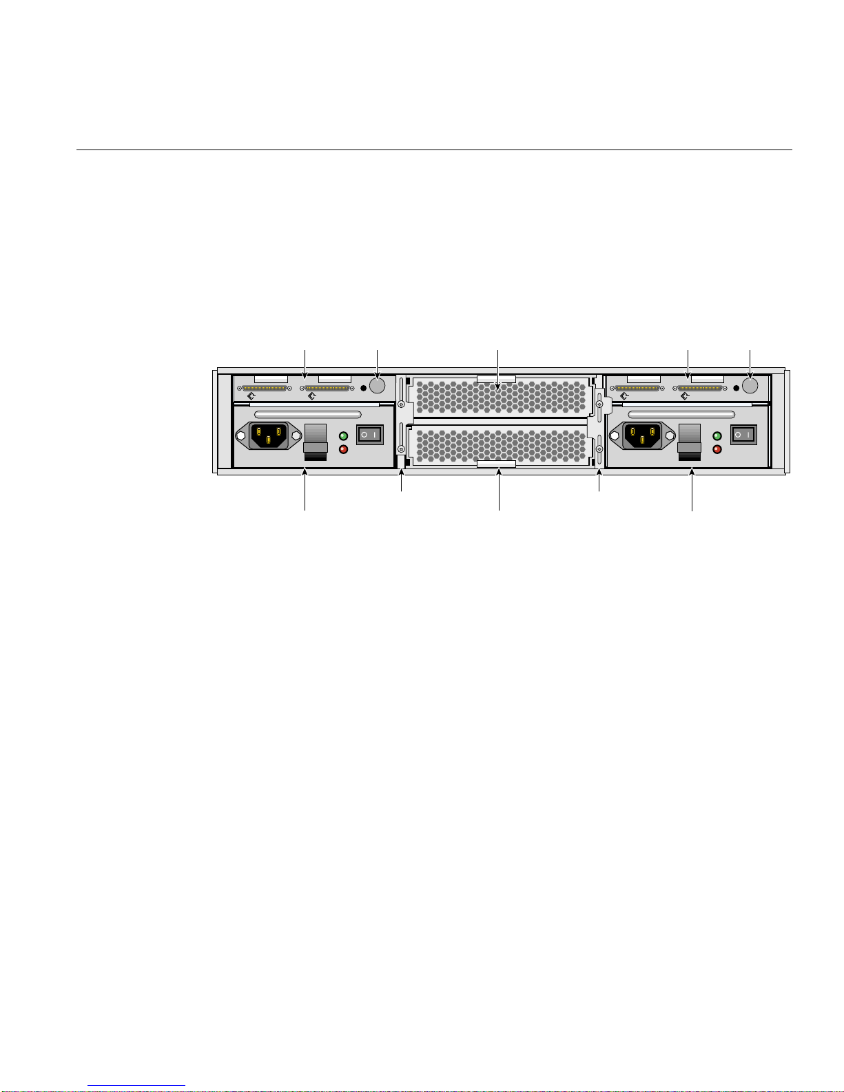
Figure 1-3 shows the back of a fully configured redundant enclosure with two cooling
modules, two PSU modules, and two I/O modules.
OUTPUT
GOOD
FAULT
ID range
Cooling module
Retaining bracket Retaining bracket
PSU PSU
Cooling module
Figure 1-3 Rear Module Location in Redundant Configuration
I/O moduleI/O module
CHANNEL 2 CHANNEL 1CHANNEL 2 CHANNEL 1
OUTPUT
GOOD
FAULT
ID range
007-4428-003 3
Page 20
1: Storage System Features
Front Panel LEDs
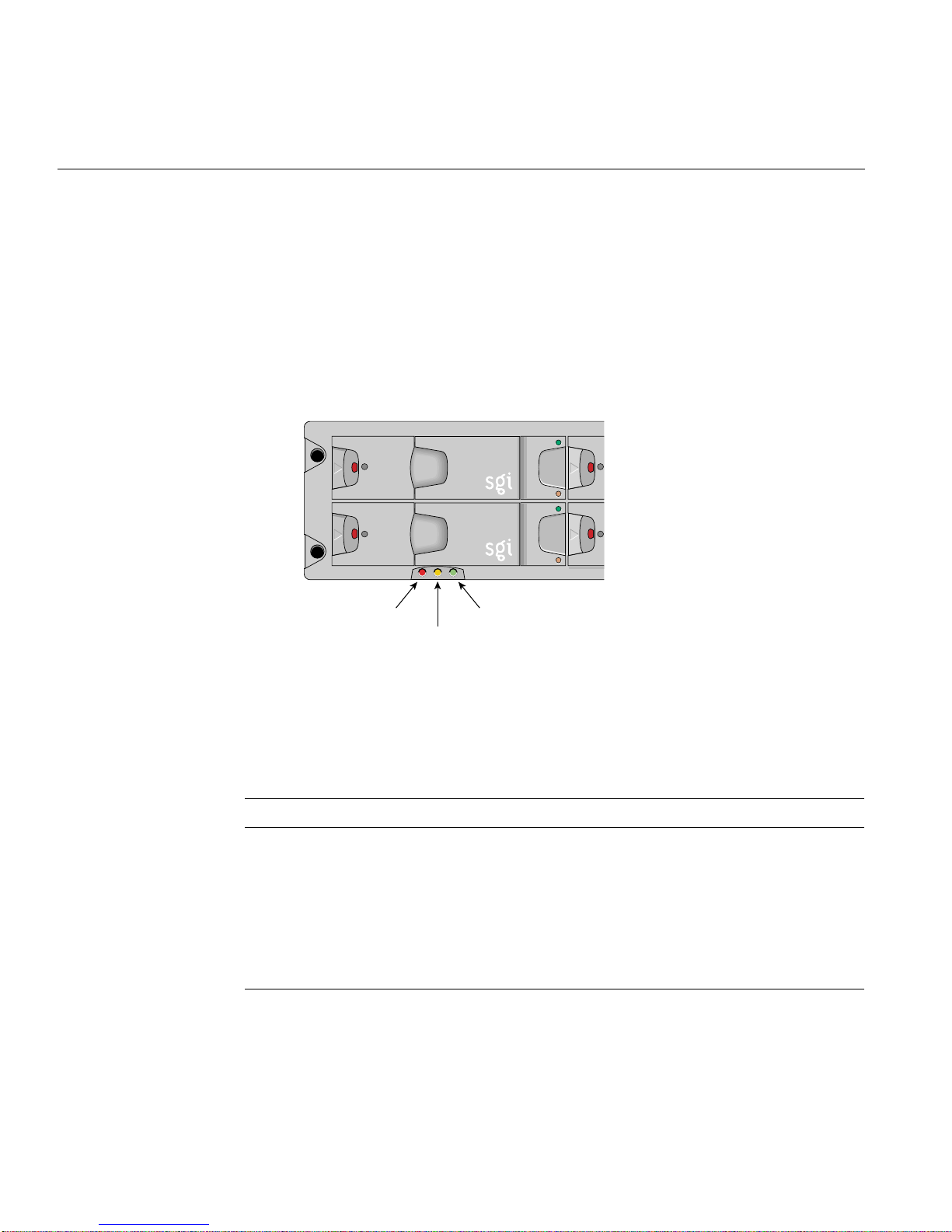
The Enclosure System Interface/Operators (ESI/Ops) panel consists of three status
indicator LEDs that are locatedon the front of theenclosure. The ESI/Ops panel provides
the enclosure with a micro controller that is used to monitor and control all elements of
the enclosure. Each element (system, power, and cooling status) is interfaced to the
processor. Figure 1-4 shows the ESI/Ops panel.
System status Cooling status
Power status
Figure 1-4 ESI/Ops Panel
Table 1-1 summarizes the functions of the LEDs on the ESI/Ops panel. See Chapter 4 for
descriptions of common problems, with possible solutions, that can occur with your SGI
TP900 system.
Table 1-1 ESI/Ops LED States
LED LED State and Meaning
System status Green signifies that power is applied to the enclosure.
Amber signifies that the ESI processor has failed.
Power status Green signifies that the power supplies are functioning normally.
Amber signifies that there is a PSU failure in a dual-PSU enclosure.
In the event of a PSU failure in a single-PSU enclosure, all LEDs are off.
Cooling status Green signifies that all fans are functioning normally.
Amber signifies that there is a fan failure.
4 007-4428-003
Page 21

Plug-in Modules
Plug-in Modules
The front of the enclosure contains 8 drive bays, each of which accommodates a plug-in
drive carrier module. The rear of the enclosure contains 6 module bays that house power
supply, cooling, and SCSI I/O modules. This section describes the component modules
in the storage system, as follows:
• Drive Carrier Modules
• Power Supply Module
• Input/Output (I/O) Module
• Cooling Module
• Dummy Carrier Modules
• Blank Modules
007-4428-003 5
Page 22
1: Storage System Features
Drive Carrier Modules
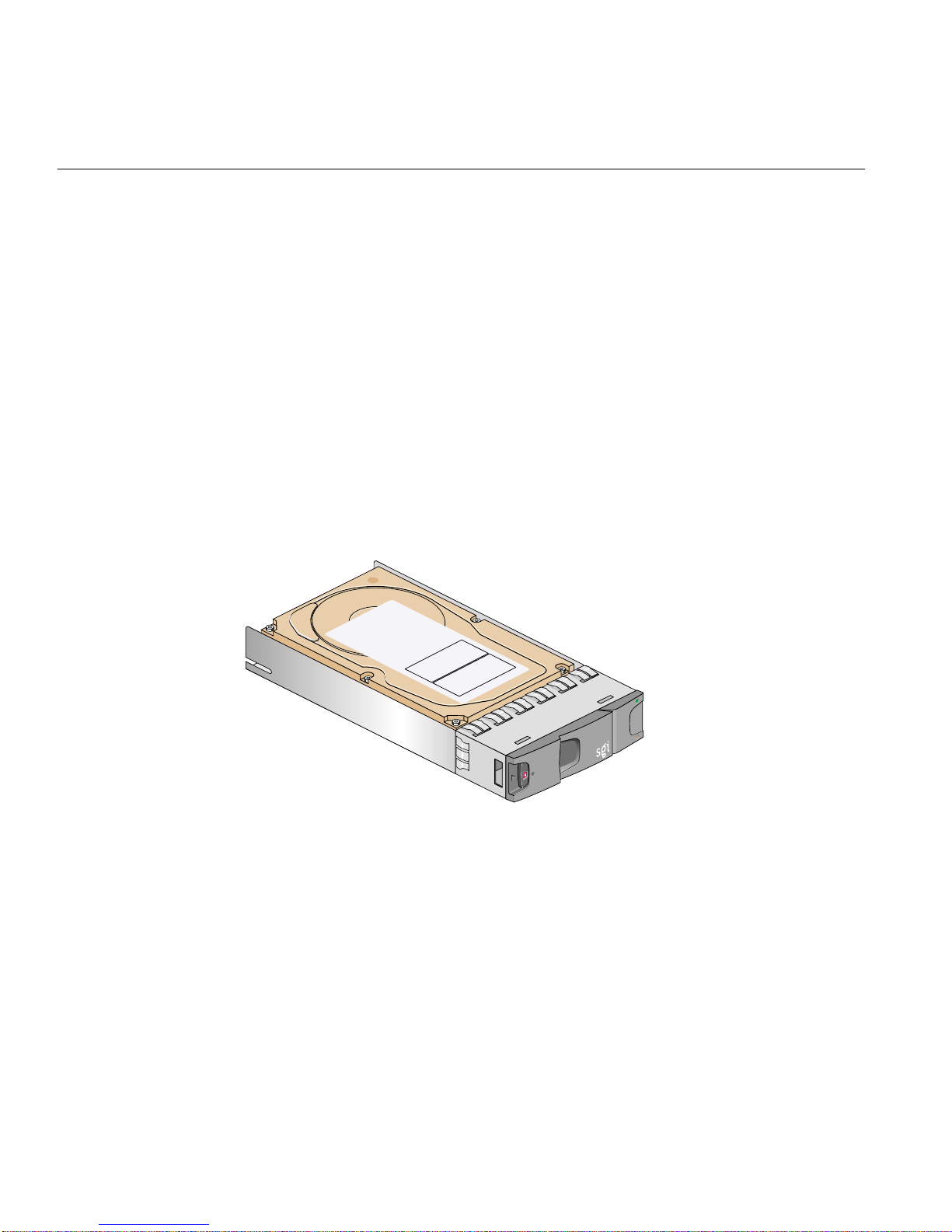
The drive carrier module comprises a hard disk mounted in a carrier. Each drive bay will
house a single 1.0-inch high, 3.5-inch disk drive in its carrier. Each disk drive is enclosed
in a die-cast aluminum carrier that provides excellent thermal conduction, radio
frequency and electromagnetic induction protection, and maximum physical protection
of the drives.
The front cap also supports an ergonomic handle that provides the following functions:
• Camming of carrier into and out of drive bays.
• Spring-loading of the drive into the backplane connector.
• An anti-tamper lock operated by a torx socket type key.
Figure 1-5 shows a drive carrier module.
Figure 1-5 Drive Carrier Module
This section discusses other features of the drive carrier module, as follows:
• Drive carrier indicators
• Anti-tamper locks
• Drive information label
6 007-4428-003
Page 23
Drive Carrier Indicators
Plug-in Modules
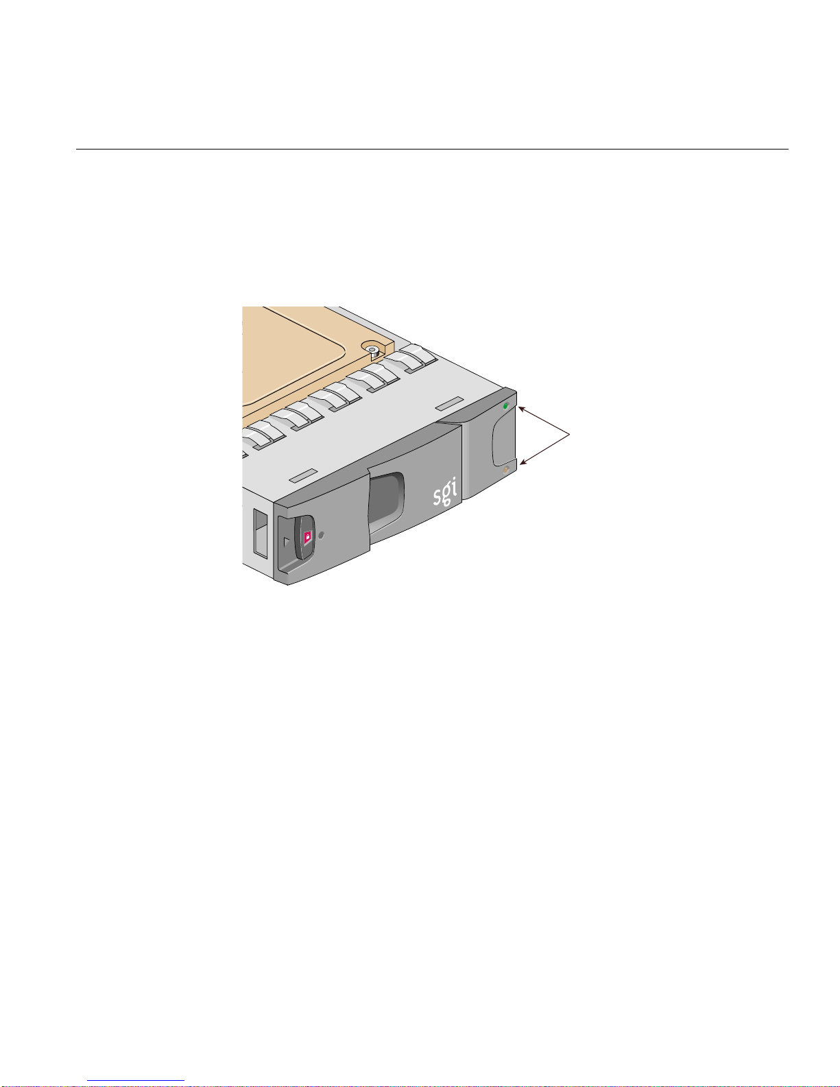
Each drive carrier incorporates two indicators, an upper (green) and a lower (amber). In
normal operation, the green indicator will be lit and will flicker as the drive operates.
Figure 1-6 shows the drive carrier indicators.
Drive carrier
indicators
Figure 1-6 Drive Carrier LED Indicators
007-4428-003 7
Page 24
1: Storage System Features
Anti-tamper Locks
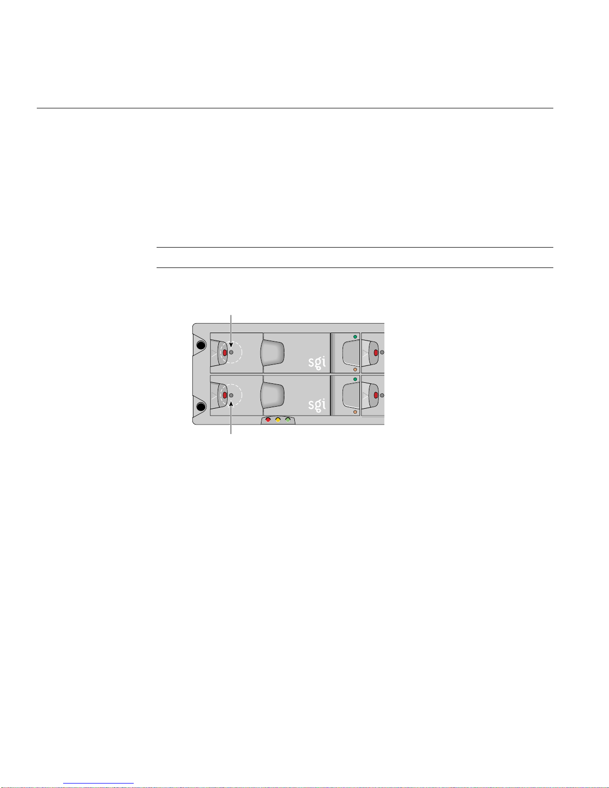
Anti-tamper locks are fitted in the drive carrier handles and are accessed through the
small cutout in the latch section of the handle. These are provided to disable the normal
“pinch” latch action of the carrier handle. See “Engaging the Anti-tamper Locks” on
page 28 for instructions on how to engage or disengage the anti-tamper lock. Figure 1-7
shows the location of the anti-tamper locks.
Note: The drives will operate with the locks either engaged or disengaged.
Anti-tamper lock
Anti-tamper lock
Figure 1-7 Anti-tamper Locks
8 007-4428-003
Page 25
Drive Information Label
Plug-in Modules
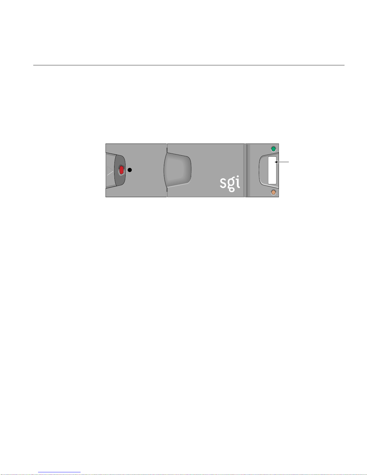
A label containing drive information is located on the drive carrier handle. The label
indicates the size (xxx GB), speed (xx kRPM), and the last five numbers of the serial
number of the drive installed in the carrier. See Figure 1-8 for an illustration of the drive
information label.
Drive
information
XXXXX
label
XXXGB XXK
Figure 1-8 Drive Information Label
007-4428-003 9
Page 26
1: Storage System Features
Power Supply Module
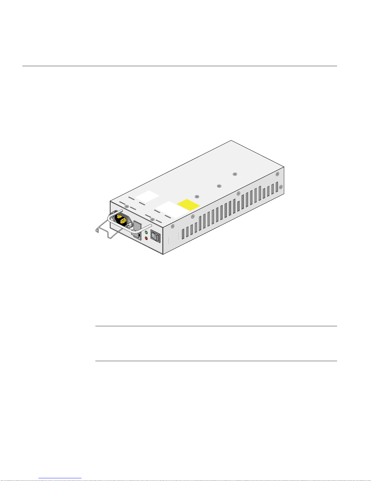
One 350-Watt plug-in power supply module (PSU) is mounted in the rear of the system.
Optionally, a second power supply module can be fitted to provide redundancy.
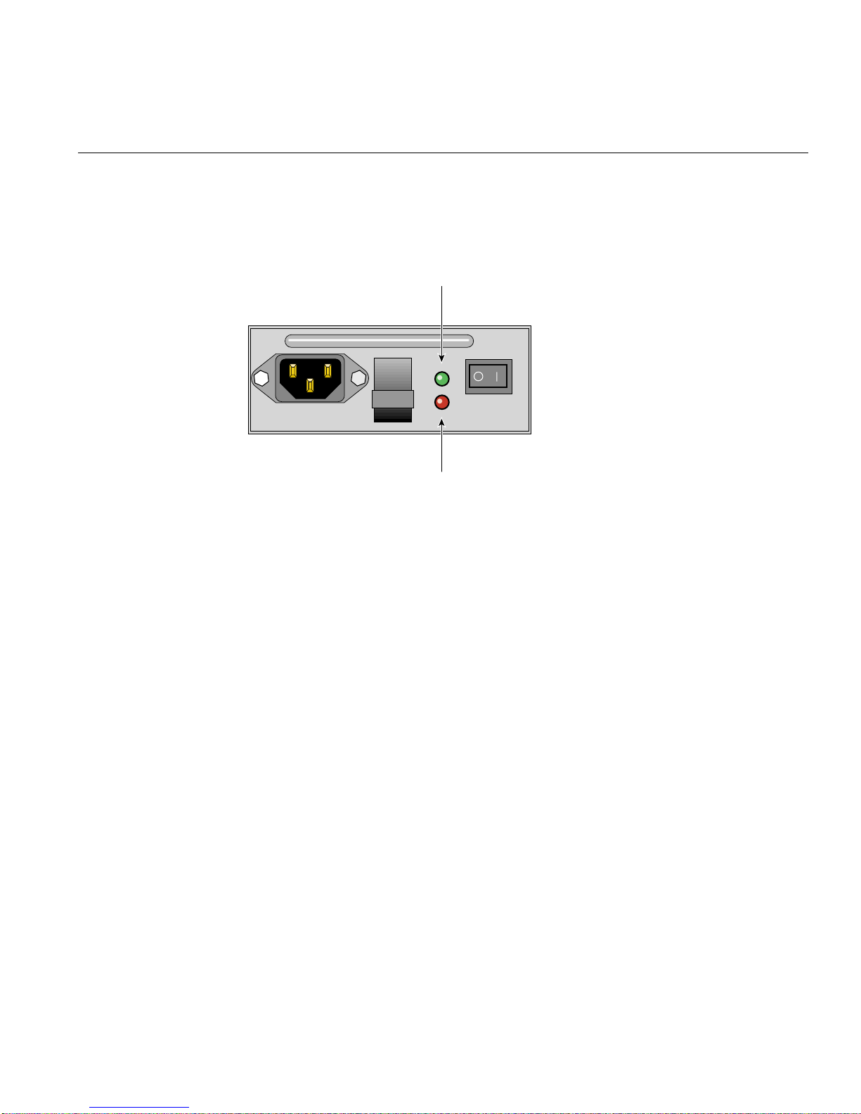
Figure 1-9 shows a PSU module.
OUTPUT
GOOD
FAULT
Figure 1-9 Power Supply Module
Power supply voltage operating ranges are nominally 115 V or 230 V, and are selected
automatically.
In a redundant configuration, the modules operate together; if one fails, the other
maintains the power supply while the faulty unit is replaced.
Important: Module replacement should only take a few minutes to perform but must be
completed within 10 minutes from removal of the failed module. Alternatively, if a
replacement power supply module is not available, a power supply blanking module
must be fitted after removing the faulty module.
10 007-4428-003
Page 27
Plug-in Modules
Two LED indicators are located on the front panel of the powersupply. Figure 1-10 shows
the power supply indicators.
Power output
OUTPUT
GOOD
FAULT
Power supply failure LED
Figure 1-10 Power Supply Indicators
The green LED indicates good power output. The amber LED indicates power supply
failure.
007-4428-003 11
Page 28
1: Storage System Features
Input/Output (I/O) Module
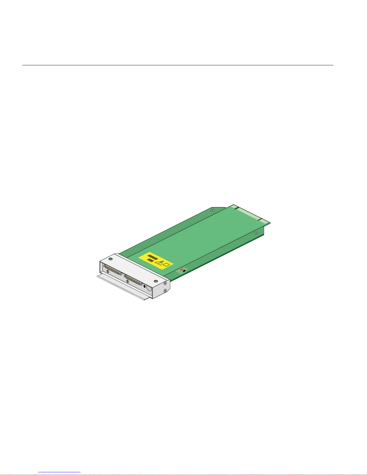
Two I/O modules are mounted in therear of the system utilizing Ultra-3 SCSI interfacing
with the host computer system. Two I/O module configurations are available, as follows:
• The 1 x 8 configuration is used to create a SCSI bus structure with one string of 8
• The 2 x 4 configuration is used to create a SCSI bus structure with two strings of 4
Figure 1-11 shows a standard Ultra-3 I/O module.
drives. It consists of one standard I/O module with two VHDCI connectors for
main I/O purposes and a switch to set the SCSI-ID range. The second module is a
loopback PCB with no external connectors.
drives. The two modules are the standard I/O modules with two VHDCI
connectors for main I/O purposes.
CHANNEL 2
CHANNEL 1
Figure 1-11 Ultra-3 SCSI I/O Module
12 007-4428-003
Page 29
Plug-in Modules
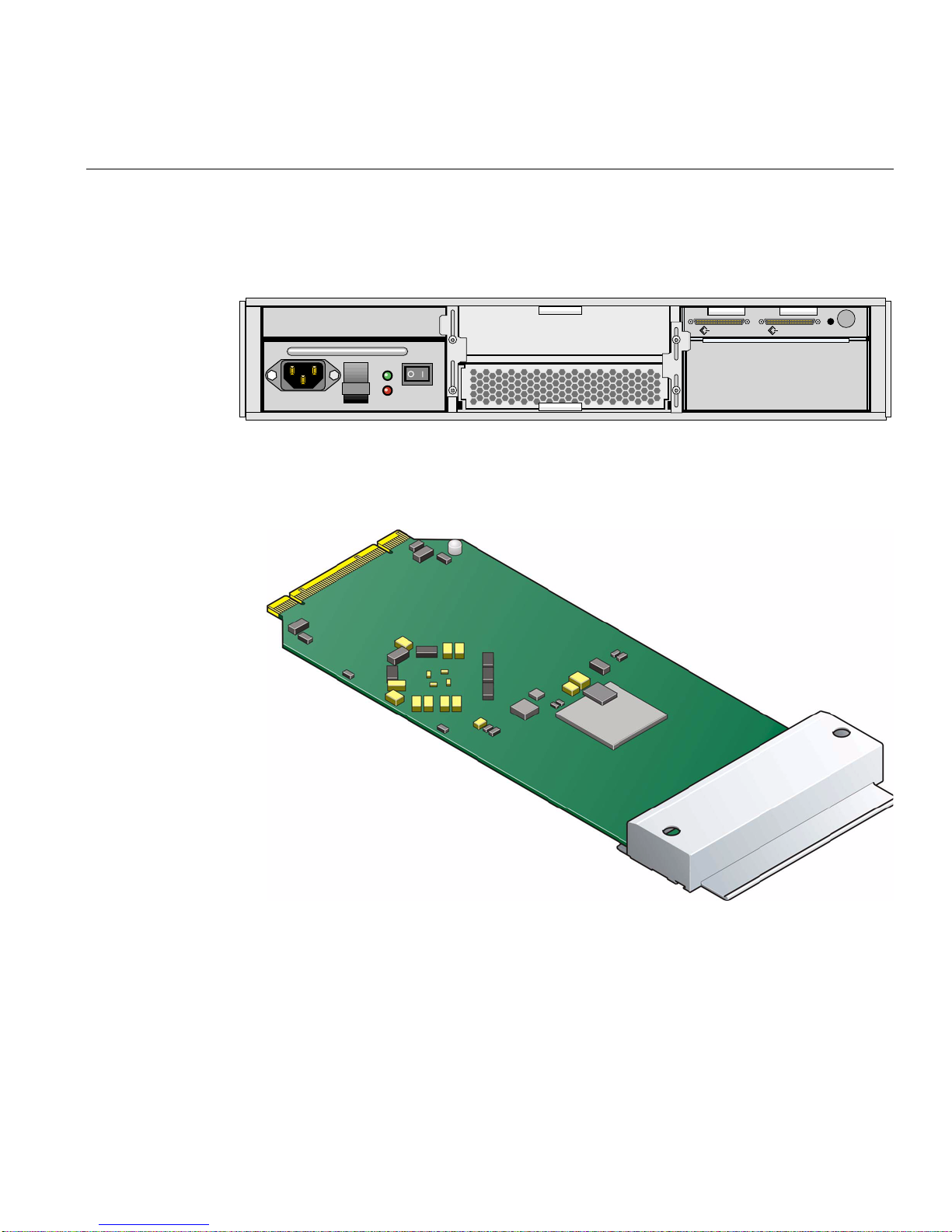
Figure 1-12 shows the rear view of an enclosure with I/O modules in a 1 x 8
configuration.
CHANNEL 2 CHANNEL 1
OUTPUT
GOOD
FAULT
Figure 1-12 I/O Modules in 1 x 8 Configuration
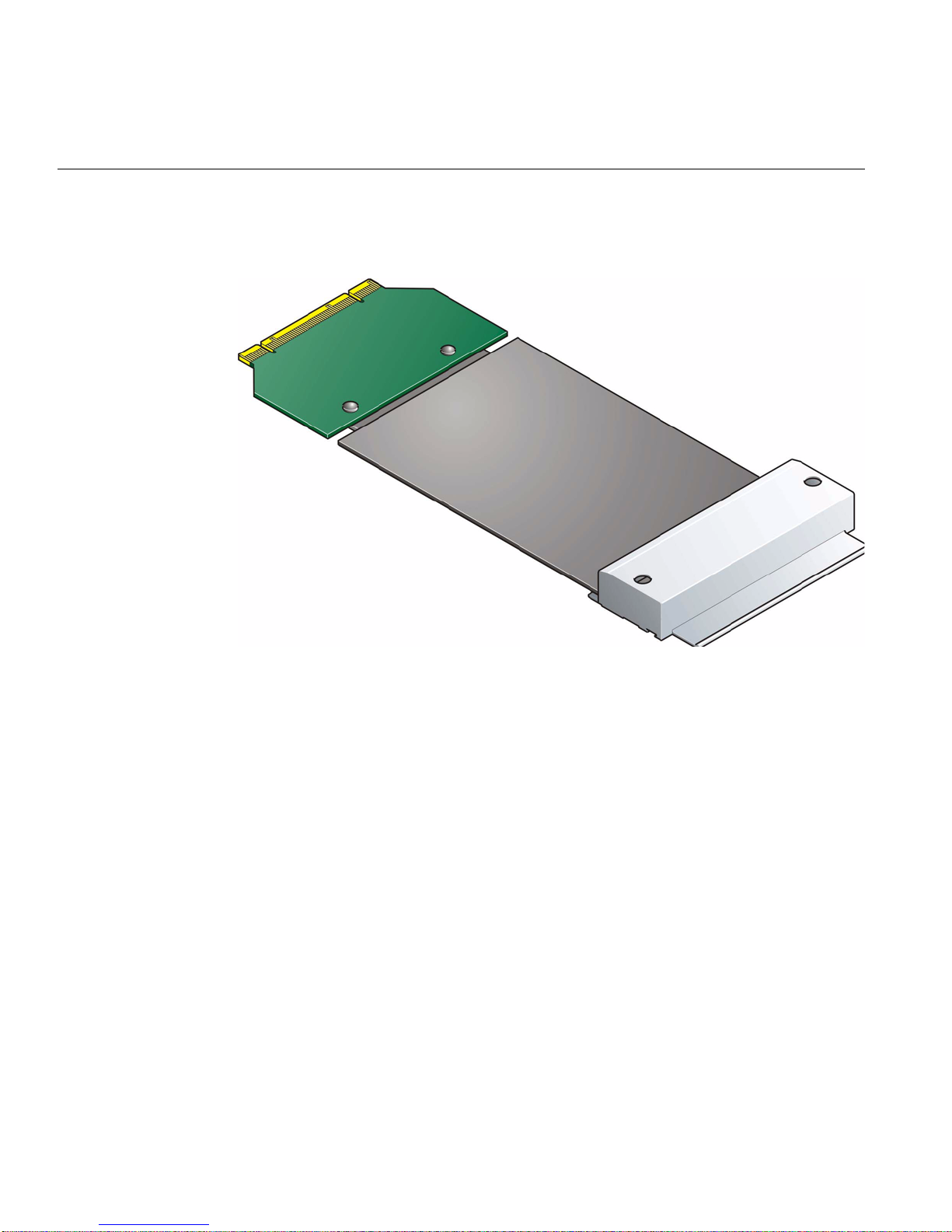
Figure 1-13 shows a U160/U320 loopback module.
Figure 1-13 1 x 8 configuration U160/U320 Loopback Module
007-4428-003 13
Page 30
1: Storage System Features
Figure 1-14 shows a U160 loopback module.
Figure 1-14 1 x 8 configuration U160 Loopback Module
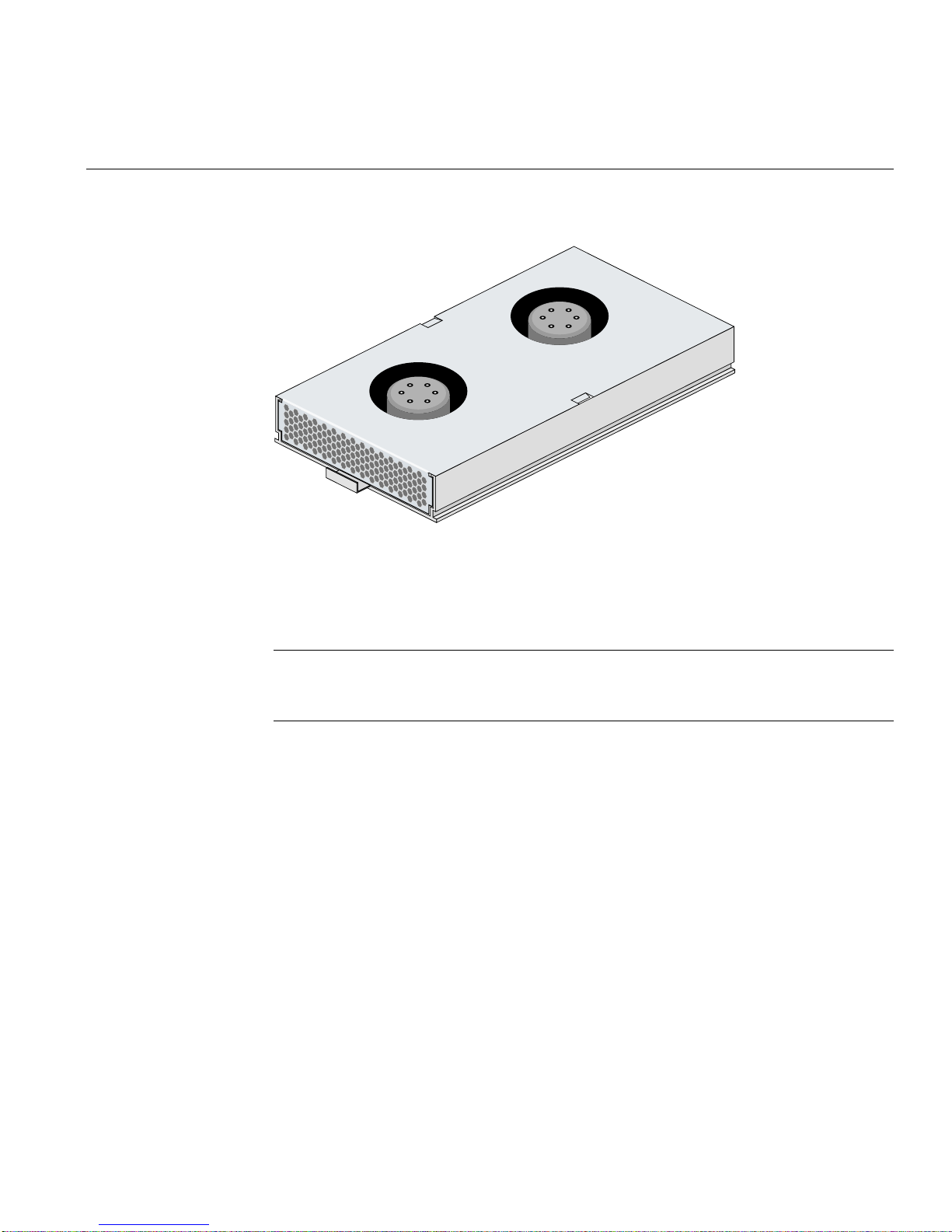
Cooling Module
One cooling plug-in module is mounted in the rear of the system. Optionally, a second
cooling module can be fitted to provide greater redundancy. The cooling modules
connect to the backplane for power and status signal connections. The modules pull air
from a plenum behind the drive backplane and exhaust the warm air at the rear of the
enclosure. Figure 1-15 shows a cooling module.
14 007-4428-003
Page 31
Plug-in Modules
Figure 1-15 Cooling Module
In a redundant configuration, the modules operate together; if one fails, the other
maintains adequate cooling to the system while the faulty unit is replaced.
Caution: Do not remove a module unless a replacement can be immediately added. This
is particularly important in a single-cooling module system, which will very quickly
overheat unless a properly functioning cooling module is installed.
007-4428-003 15
Page 32

1: Storage System Features
Dummy Carrier Modules
Dummy carrier modules are provided for installation in all unused drive bays. They are
designed as integral drive module front caps with handles and must be installed in all
unused drive bays to maintain a balanced airflow.
Caution: If any modules are missing, operation of the enclosure will disrupt the airflow
and the drives will not receive sufficient cooling. It is essential that all apertures be filled
before operating the unit. Dummy carriers are available for this purpose.
Blank Modules
Blank modules must be fitted in all vacant bays at the rear of the enclosure to maintain
airflow and ensure correct operation. Blank modules are available forthe cooling module
bays and the power supply module bays.
Caution: If any modules are missing, operation of the enclosure will disrupt the airflow
and the drives will not receive sufficient cooling. It is essential that all apertures be filled
before operating the unit. Blank modules are available for this purpose.
16 007-4428-003
Page 33
Storage System Bay Numbering Convention
A bay is defined as the space required to house a single module. In the front of the
enclosure, this is the space required by a single 1.0-inch high 3.5-inch disk drive in its
carrier module. In the rear of the enclosure, this is the space required by a single PSU,
I/O, or cooling module.
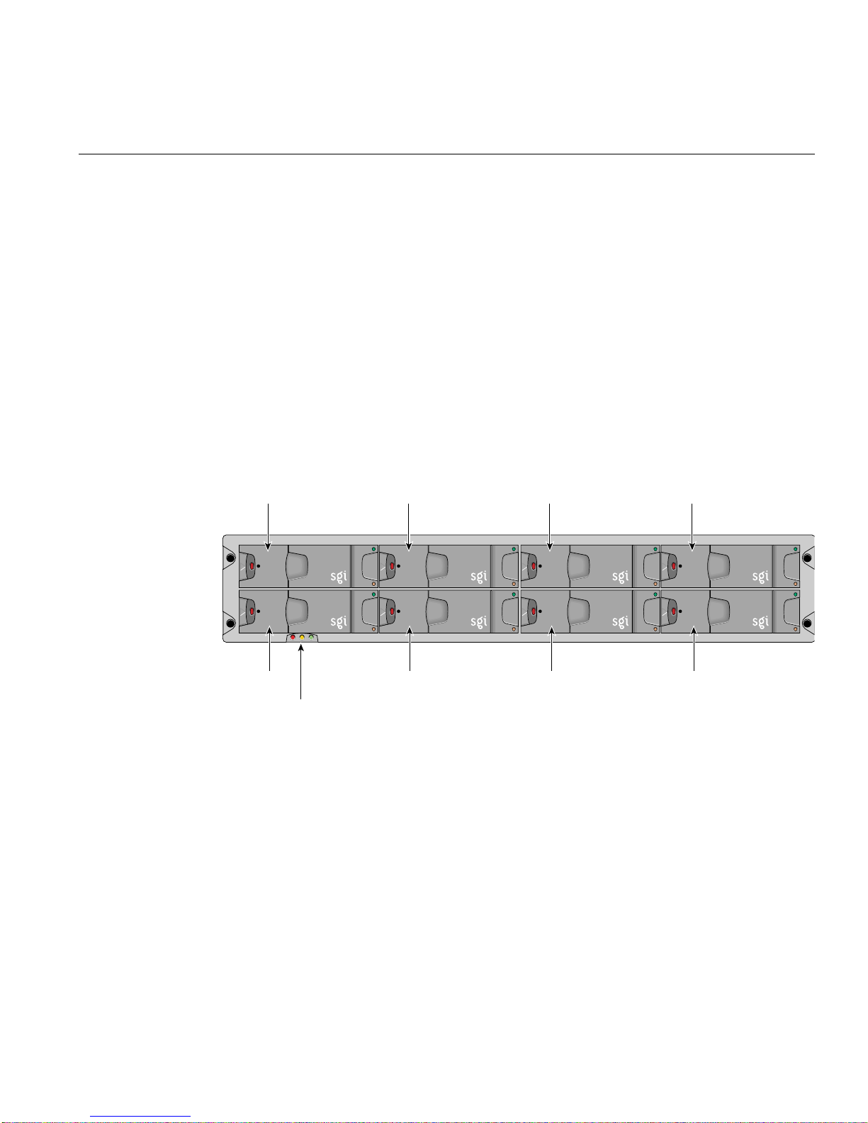
The SGI TP900 system has 8 drive bays in the front of the enclosure—2 rows of 4 bays. A
front bay is identified by a row/column fraction. Rows are numbered 1 to 2 from top to
bottom, and columns are numbered 1 to 4 from left to right, viewed from the front. For
example, drive 1/2 refers to the bay located in row 1 (top) and column 2 (second from the
left).
Figure 1-16 shows the numbering convention for the drive modules.
Drive 1/1 Drive 1/2 Drive 1/3 Drive 1/4
Storage System Bay Numbering Convention
Drive 2/1 Drive 2/2 Drive 2/3 Drive 2/4
LED status
indicators
Figure 1-16 Drive Bay Numbering
007-4428-003 17
Page 34
1: Storage System Features
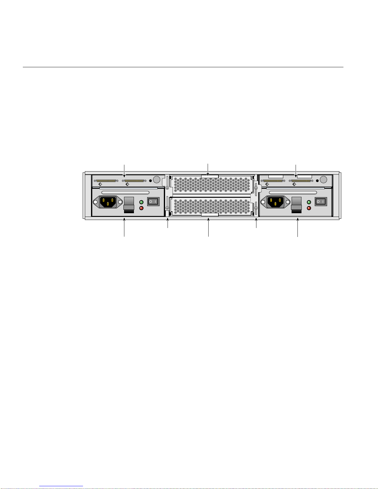
The SGI TP900 system has 6 module bays at the rear—2 rows of 3 bays. A rear bay is
identified by a row/column fraction. Rows are numbered 1 to 2 from top to bottom, and
columns are numbered 1 to 3 from right to left, viewed from the rear. For example,
module 2/3 refers to the bay located in row 2 (bottom) and column 3 (third from the
right).
Figure 1-17 shows the location and numbering convention for the rear-bay modules.
I/O module (1/3) I/O module (1/1)
OUTPUT
GOOD
FAULT
Cooling module (1/2)
CHANNEL 2 CHANNEL 1CHANNEL 2 CHANNEL 1
Retaining bracket Retaining bracket
Cooling module (2/2)
PSU (2/1)PSU (2/3)
Figure 1-17 Rear Module Locations and Bay Numbering
OUTPUT
GOOD
FAULT
18 007-4428-003
Page 35

Chapter 2
2. Setup and Operation
This chapter describes how to set up and operate your SGI TP900 storage system in the
following sections:
• “Unpacking and Inspecting the Storage System” on page 19
• “Connecting the Power Cord” on page 20
• “Attaching Interface Cables” on page 21
• “SCSI_ID Addressing” on page 24
• “Powering On the Enclosure” on page 26
• “Powering Off the Enclosure” on page 27
• “Engaging the Anti-tamper Locks” on page 28
Note: If you use an LSI1030 (LSI22320-R) HBA, you must upgrade the drive firmware
from revision 2741 to revision 2743 in order to have the full benefit of U320 disk drive
speed. The firmware upgrade is normally performed by an SGI service engineer.
Unpacking and Inspecting the Storage System
Remove the storage system from the packaging container and check that all accessories
are included. Inspectthe packaging container for evidenceof mishandling during transit.
If the packaging container is damaged, photograph it for reference. After removing the
contents, keep the damaged container and the packing materials.
Inspect the storage system and accessories for damage. If the contents appear damaged,
file a damage claim with the carrier immediately. For installations under U.S. auspices,
notify the Customer Support Call Center (CSCC) for any missing, incorrect, or damaged
items. Elsewhere, follow local policies.
007-4428-003 19
Page 36

2: Setup and Operation
Connecting the Power Cord
To connect a power cord to power supply modules, follow these steps:
1. For redundant configurations, attach the bifurcated power cord to the power supply
modules.
2. Attach the power cord to the in-line IEC connector.
Note: These power-splitting cables are provided so that the system is operated from
a single power source, thus providing a single point of disconnect.
A standby LED on the ESI/Ops panel indicates whether AC power is present.
For non-redundant systems using one power supply module, connect the power cord to
the power supply module and to the power source.
Perform these checks to ensure that a safe grounding system is provided:
1. If a rack distribution system is being used, perform these tasks:
– Ensure power is removed from the rack.
– Connect the supplied power cord to the rack distribution and the enclosure.
2. If a direct connection is made with the power cord, ensure that it is connected to the
enclosure.
Caution: Someelectrical circuits couldbe damaged if external signal cables or power
control cables are present during the grounding checks.
3. Check for continuity between the earth pin of the power cord on one of the power
supply modules (or rack inlet) and any exposed metal surface of the SGI TP900
enclosure.
20 007-4428-003
Page 37

Attaching Interface Cables
This section explains which of the connectors on the I/O modules should be used to
connect external Ultra-3 SCSI-compatible cables.
As seen from the rear of an I/O module, the connector on the right-hand side connects
to channel 1 (device bays 1/1, 2/1, 1/2, 2/2). The connector on the left-hand side
connects to channel 2 (device bays 1/3, 2/3, 1/4, 2/4). This applies to I/O modules
installed in either location (1/1 or 1/3).
Table 2-1 shows the cables that are supported
Table 2-1 Supported cables
Cable Combination SGi Part Number
Cables for U160/U320 Max .(1m) 013-1043-001
Cables for U160/U320 Max .(2m) 018-1046-001
Attaching Interface Cables
1 x 8 Configuration
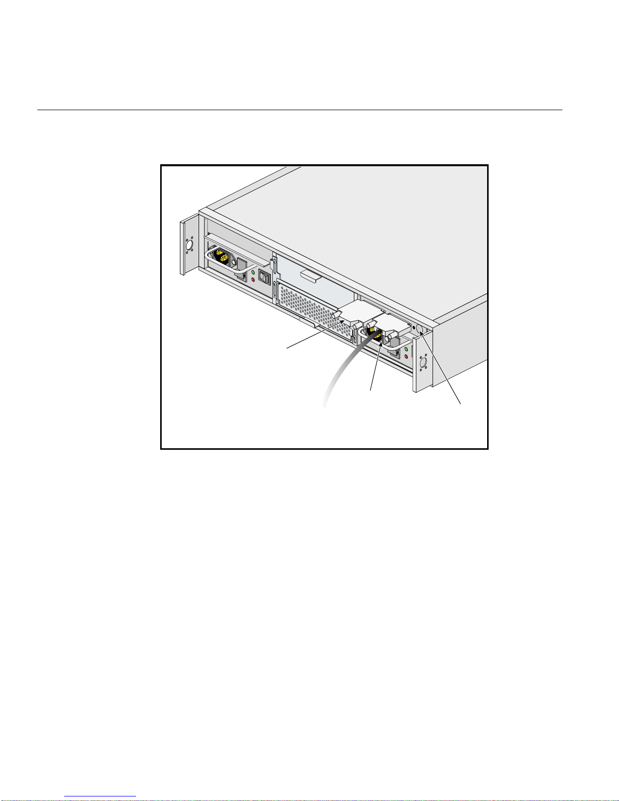
Connect the interface cable to the channel 1 connector and attach a terminator to the other
I/O connector, as shown in Figure 2-1.
Caution: External termination must be fitted to the unused I/O connector to ensure
termination of the SCSI bus. I/O modules do not contain any bus termination.
007-4428-003 21
Page 38
2: Setup and Operation
O
U
T
P
U
T
G
O
O
D
F
A
U
L
T
Terminator
C
H
A
N
N
E
L
1
C
H
A
N
N
E
L
2
O
U
T
P
U
T
G
O
O
D
F
A
U
L
T
Channel 1
Figure 2-1 Attaching Interface Cable on 1 x 8 Configuration
ID range
22 007-4428-003
Page 39
2 x 4 Configuration
Attaching Interface Cables
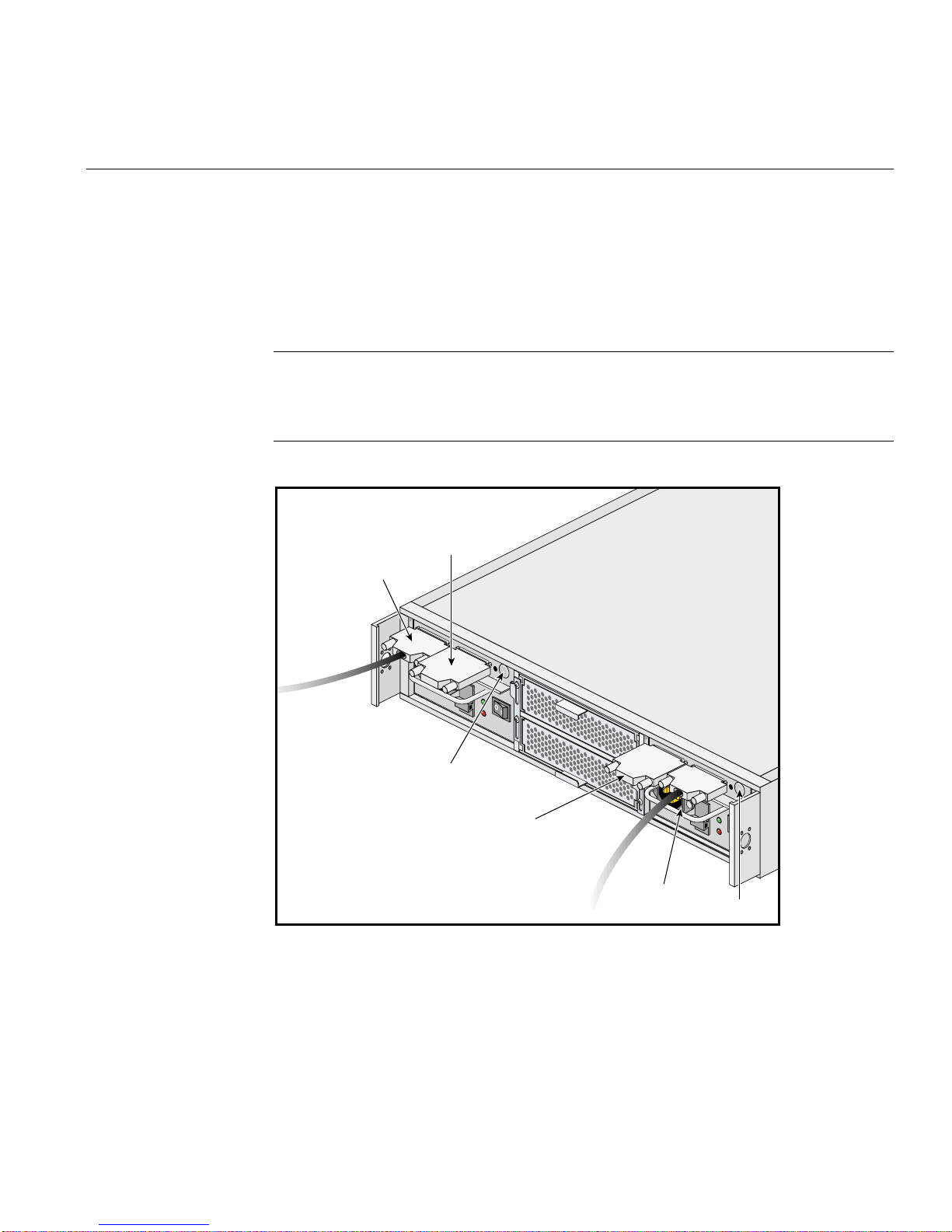
Connect an interface cable to the channel 1 connector on I/O module 1/1, and then
connect another interface cable to the channel 2 connector on I/O module 1/3, as shown
in Figure 2-2. Attach terminators to the two unused I/O connectors.
Caution: External termination must be fitted to all unused I/O connectors to ensure
termination of the SCSI bus. I/O modules do not contain any bus termination. If you are
using only one of the two I/O modules, a termination is required only on the connector
that corresponds to the channel being used, as shown in Figure 2-2.
Terminator 1
Channel 2
C
H
A
N
N
E
L
1
C
H
A
N
N
E
L
2
O
U
T
P
U
T
G
O
O
D
F
A
U
L
T
C
H
A
N
N
E
L
ID range
Terminator 2
Channel 1
1
C
H
A
N
N
E
L
2
O
U
T
P
U
T
G
O
O
D
F
A
U
L
T
ID range
Figure 2-2 Attaching Interface Cable on 2 x 4 Configuration
007-4428-003 23
Page 40
2: Setup and Operation
Important: In a 2 x 4 configuration, the termination for each channel is located on the
other I/O module from where the interface cable is connected. For example, the
terminator for channel 1 is located on the left I/O module (1/3), whereas the interface
cable is connected to the right I/O module (1/1). See Figure 2-2 for an illustration of the
proper cable and terminator configuration.
SCSI_ID Addressing
This section shows the SCSI_ID base address for each drive in 1 x 8 and 2 x 4
configurations. See “Storage System Bay Numbering Convention” on page 17 for the
drive module numbering convention.
1x 8 Configuration
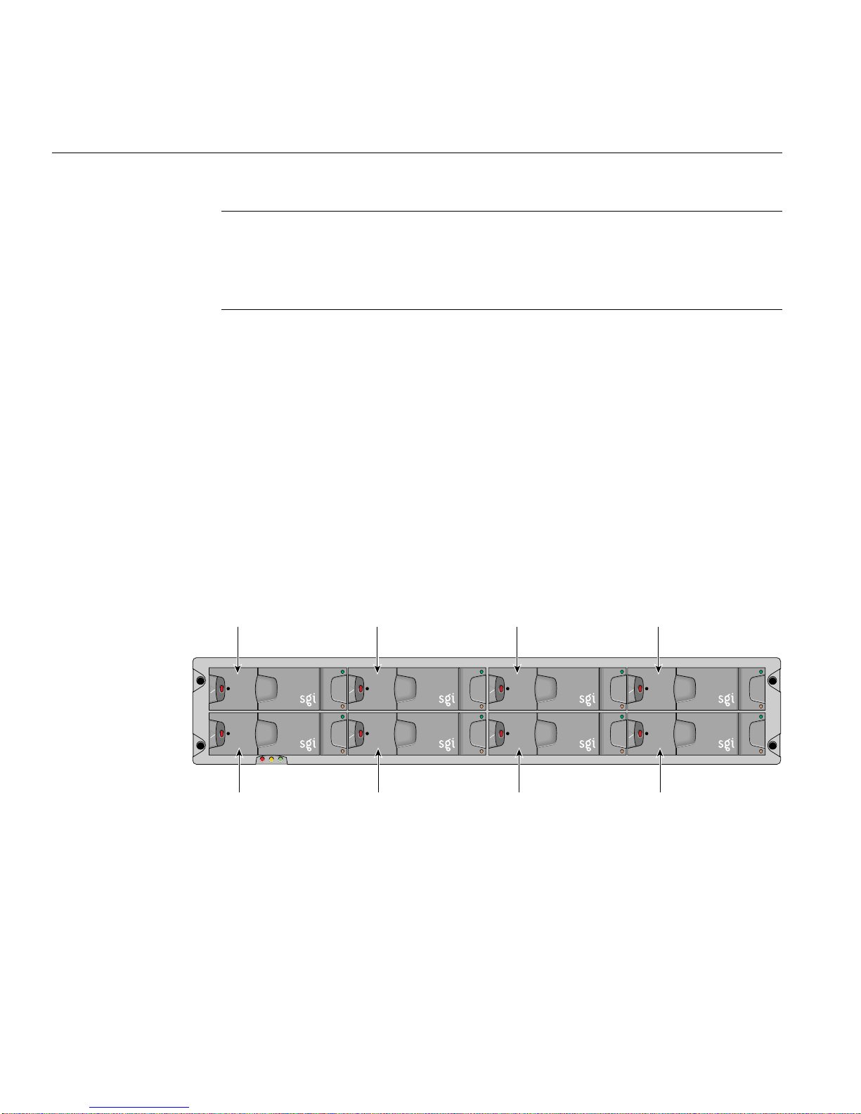
In a 1 x 8 configuration with a loopback module installed, the single I/O module (1/1)
controls the range of all the drives. Figure 2-3 shows the SCSI_ID base address for each
drive.
SCSI_ID 1 SCSI_ID 3 SCSI_ID 11SCSI_ID 9
SCSI_ID 2 SCSI_ID 4 SCSI_ID 10 SCSI_ID 12
Figure 2-3 1 x 8 SCSI_ID Addressing
24 007-4428-003
Page 41
2 x 4 Configuration
SCSI_ID Addressing
Table 2-2 shows the drive enclosure device addressing for each Range ID in a 1 x 8
configuration.
Table 2-2 Drive enclosure device addressing
Range ID Device Slot* 1/1 2/1 1/2 2/2 1/3 2/3 1/4 2/4
0 SCSI_ID 012389AB
1 SCSI_ID 12349ABC
* View from the front of the enclosure.
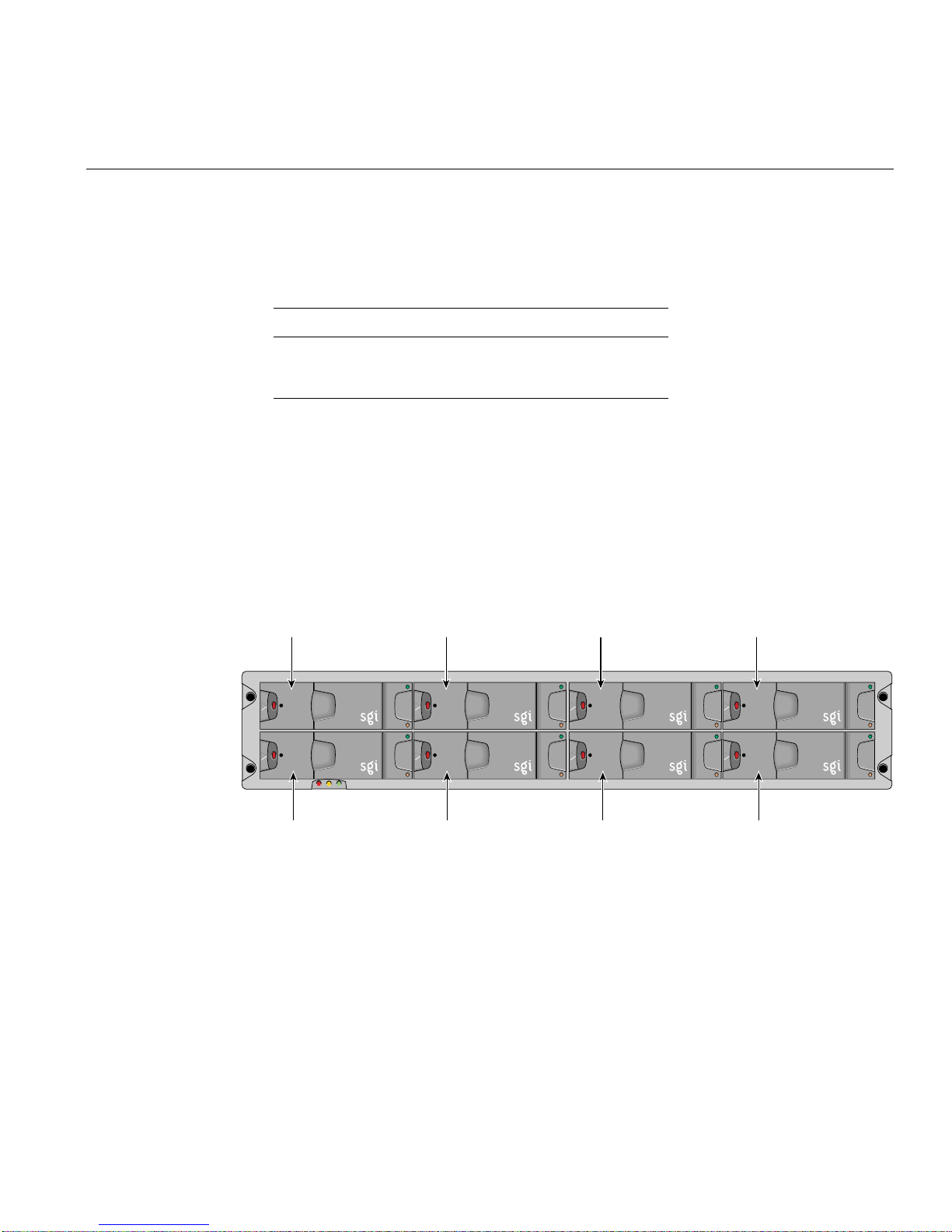
In a2 x 4 configuration, the range defined by I/O module 1/3 controls the IDs of the right
4 drives (1/3, 1/ 4, 2/3, 2/4), and I/O module 1/1 controls the IDs of the left 4 drives
(1/1, 1/2, 2/1, 2/2). Figure 2-4 shows the SCSI_ID base address for each drive.
SCSI_ID 1 SCSI_ID 3 SCSI_ID 3SCSI_ID 1
SCSI_ID 2 SCSI_ID 4 SCSI_ID 2 SCSI_ID 4
Figure 2-4 2 x 4 SCSI_ID Addressing
007-4428-003 25
Page 42

2: Setup and Operation
Table 2-3 shows the shows the drive enclosure device addressing for each Range ID in a
2 x 4 configuration.
Table 2-3 Drive enclosure device addressing
Range ID Device Slot*
1/1
or
1/3
2/1
or
2/3
1/2
or
1/4
2/2
or
2/4
0 SCSI_ID 0 1 2 3
11234
22345
33456
44567
55678
66789
7789A
889AB
9 SCSI_ID 9 A B C
* View from the front of the enclosure.
Powering On the Enclosure
Follow these steps to power on the enclosure:
Caution: Before powering on the enclosure, ensure that all the modules are firmly seated
in their correct bays. Do not operate the subsystem until the ambient temperature is
within the specified operating range. If the drives have been recently installed, ensure
they have had time to acclimatize before operating them.
26 007-4428-003
Page 43

Powering Off the Enclosure
1. Apply AC power to the enclosure. Turn the power supply module(s) switch to the
ON position. The green Power Output LED should be lit and the red Fault LED
should be off.
Note: In a dual-PSU system, it does not matter which PSU is powered on first.
2. All LEDs on the ESI/Ops Panel should be lit green, and the disk drive motors
should start when the enclosure power is activated.
Note: All LEDs on the ESI/Ops panel should be lit green when power is applied,
which indicates that the system is functioning correctly. If any show amber, then a
problem exists. See Chapter 4 for troubleshooting information.
All drives in the enclosure should automatically start their motors after power is applied.
If this has not occurred, there may be a power problem (a power fault indication would
normally be active).
Powering Off the Enclosure
To power off the enclosure, switch off the power supply modules installed in the
enclosure.
007-4428-003 27
Page 44
2: Setup and Operation
Engaging the Anti-tamper Locks
Each drive carrier handle has an anti-tamper lock, which is accessed through the small
cutout in the latch section of the handle. Drives are supplied with the locks set in the
unlocked position. A lock key is provided with the system.
Follow these steps to activate the locks:
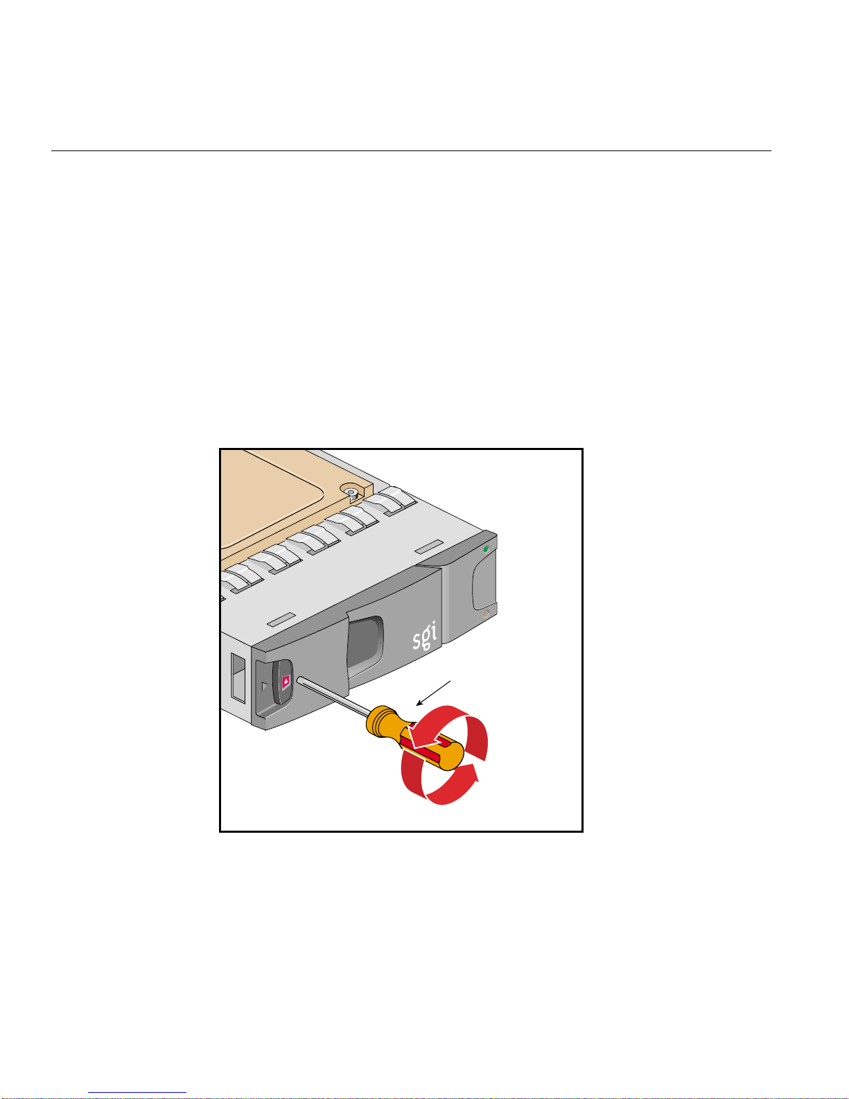
1. Carefully insert the lock key into the lock in the handle. See Figure 2-5 for the
location of the anti-tamper lock.
2. Rotate the key in a clockwise direction until the indicator is visible in the aperture
beside the key.
Torx screwdriver
Figure 2-5 Activating an Anti-tamper Lock
3. Remove the key.
28 007-4428-003
Page 45

Engaging the Anti-tamper Locks
4. Repeat this procedure for each lock that you want to activate.
To de-activate a lock, carefully insert the lock key into the lock in the handle, and rotate
the key in a counter-clockwise direction until the indicator is no longer visible in the
aperture beside the key.
Note: A drive carrier cannot be installed if its anti-tamper lock is activated outside of the
enclosure.
007-4428-003 29
Page 46

Page 47

Chapter 3
3. Replacing Modules
This chapter shows how to replace all plug-in modules in the SGI TP900 enclosure. The
following sections are covered:
• “Pre-installation Safety Precautions” on page 32
• “Dealing with Hardware Faults” on page 32
• “Continuous Operation during Replacement” on page 32
• “Replacing Power Supply Modules” on page 33
• “Replacing Cooling Modules” on page 35
• “Replacing I/O Modules” on page 36
• “Replacing Drive Carrier Modules” on page 37
• “Component Part Numbers” on page 40
007-4428-003 31
Page 48

3: Replacing Modules
Pre-installation Safety Precautions
Observe the following safety precautions.
Warning: Hazardous voltage and current levels are present inside the storage
subsystem. The replacement of rear-bay modules should be performed only by
technically qualified personnel.
Caution: Do not remove a module unless a replacement can be immediately added. The
system must not be run without all modules in place.
Caution: Follow electrostatic discharge (ESD) precautions while replacing the plug-in
modules. Avoid contact with the backplane components and module connectors.
Dealing with Hardware Faults
Ensure that you have obtained a replacement module of the same type before removing
any faulty module.
Caution: If the SGI TP900 subsystem is powered on and you remove any module,
replace it immediately. If the subsystem is used without its modules or blanking plates
for more than a few minutes, the enclosure can overheat, causing power failure and data
loss. Such use will invalidate the warranty.
Continuous Operation during Replacement
If the enclosure contains two power supply modules, one of them can maintain power to
the subsystem while the other is replaced. A cooling module can be replaced without
SCSI data flow interruption. I/O modules can be replaced with the system powered up,
but the SCSI Channel will be down and data flow will be interrupted.
32 007-4428-003
Page 49
Replacing Power Supply Modules
Follow these steps to replace a power supply module or a power supply blank module
on the SGI TP900 enclosure:
Warning: Hazardous voltage and current levels are present inside the storage
subsystem. The replacement of rear-bay modules should only be performed by
technically qualified personnel.
Caution: Do not remove a module unless a replacement can be immediately added. The
system must not be run without all modules in place.
1. Switch off the faulty module and disconnect the power supply cord.
Note: If you have two power supply modules installed, one power supply module
will maintain power to the enclosure while the other module is replaced.
Replacing Power Supply Modules
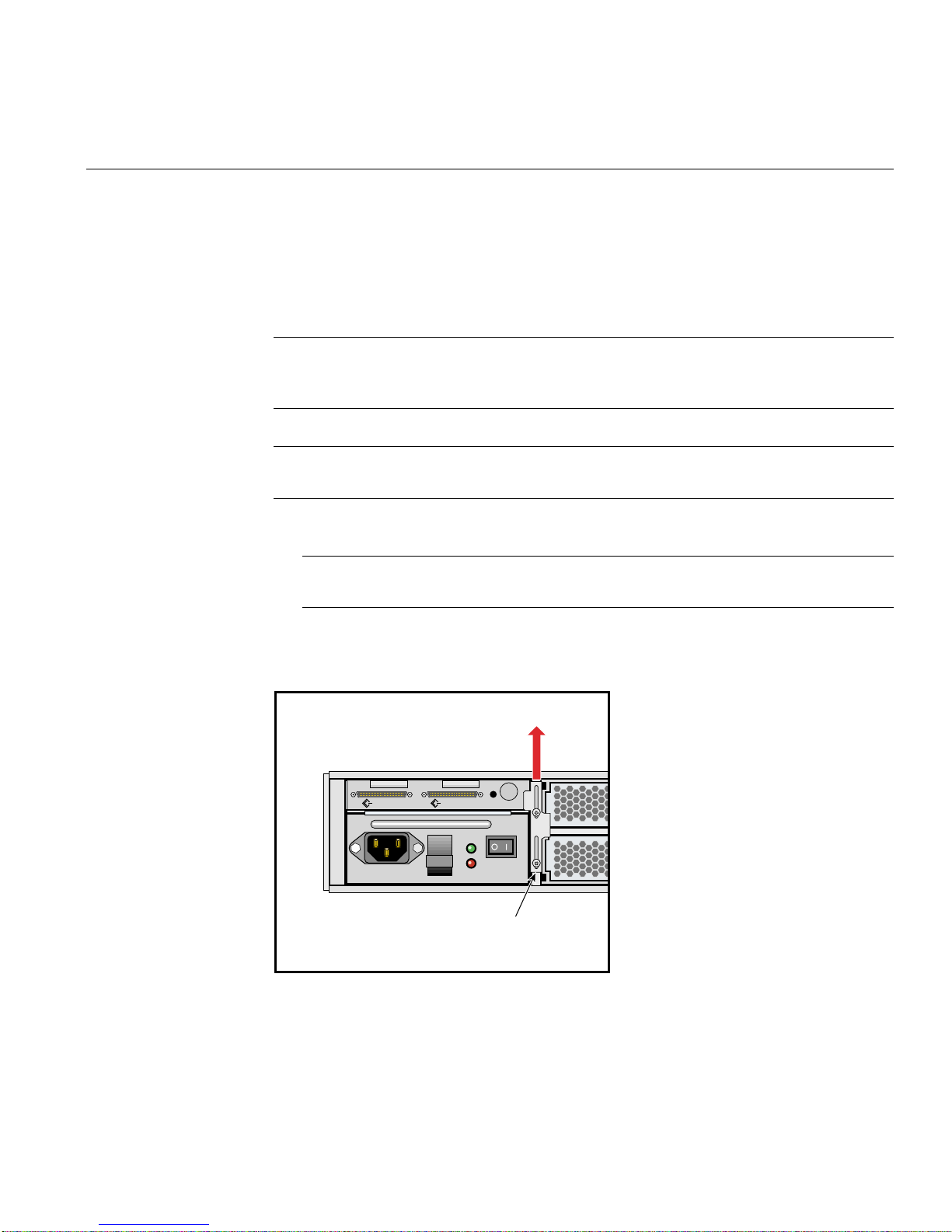
2. Loosen the screws securing the retaining bracket (see Figure 3-1) and slide the
bracket upwards, until it is clear of the side of the power supply module.
CHANNEL 2 CHANNEL 1
OUTPUT
GOOD
FAULT
Retaining bracket
Figure 3-1 Power Supply Module Retaining Bracket
007-4428-003 33
Page 50
3: Replacing Modules
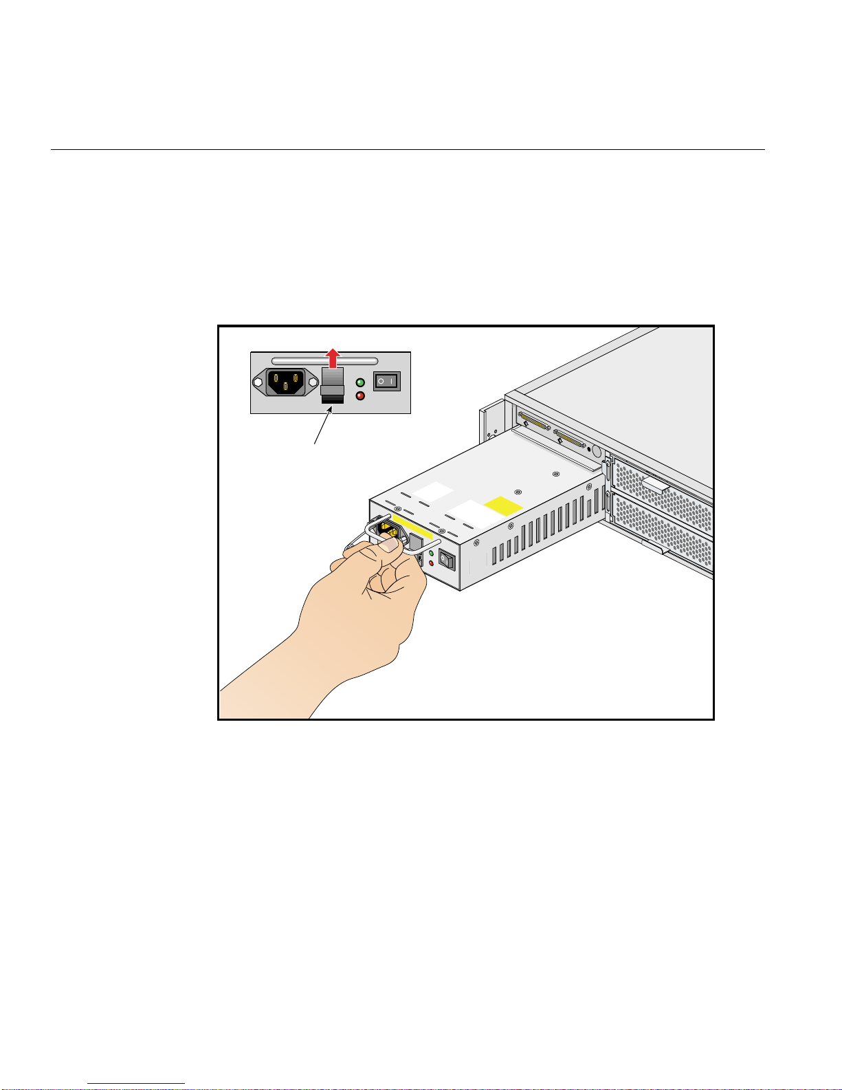
3. Grip the handle, lift the latch on the front of the PSU, and remove the PSU from the
enclosure.
4. To install a replacement module, grip the handle, lift the latch on the front of the
PSU, and slide the module into the enclosure (see Figure 3-2). The latch engages
automatically.
OUTPUT
GOOD
FAULT
C
H
A
N
N
E
L
2
C
H
A
N
N
E
L
Latch
O
U
T
P
U
T
G
O
O
D
F
A
U
L
T
1
O
U
T
P
U
T
G
O
O
D
F
A
U
L
T
Figure 3-2 Power Supply Latch and Handle
5. Return the retaining bracket to the center position and tighten the securing screws.
6. Connect the power supply cord to the power source.
34 007-4428-003
Page 51
Replacing Cooling Modules
Follow these steps to remove a cooling module or a cooling blank module from the SGI
TP900 enclosure:
Caution: Do not remove a module unless a replacement can be immediately added. This
is particularly important in a single-cooling module system which will very quickly
overheat without a properly functioning cooling module installed.
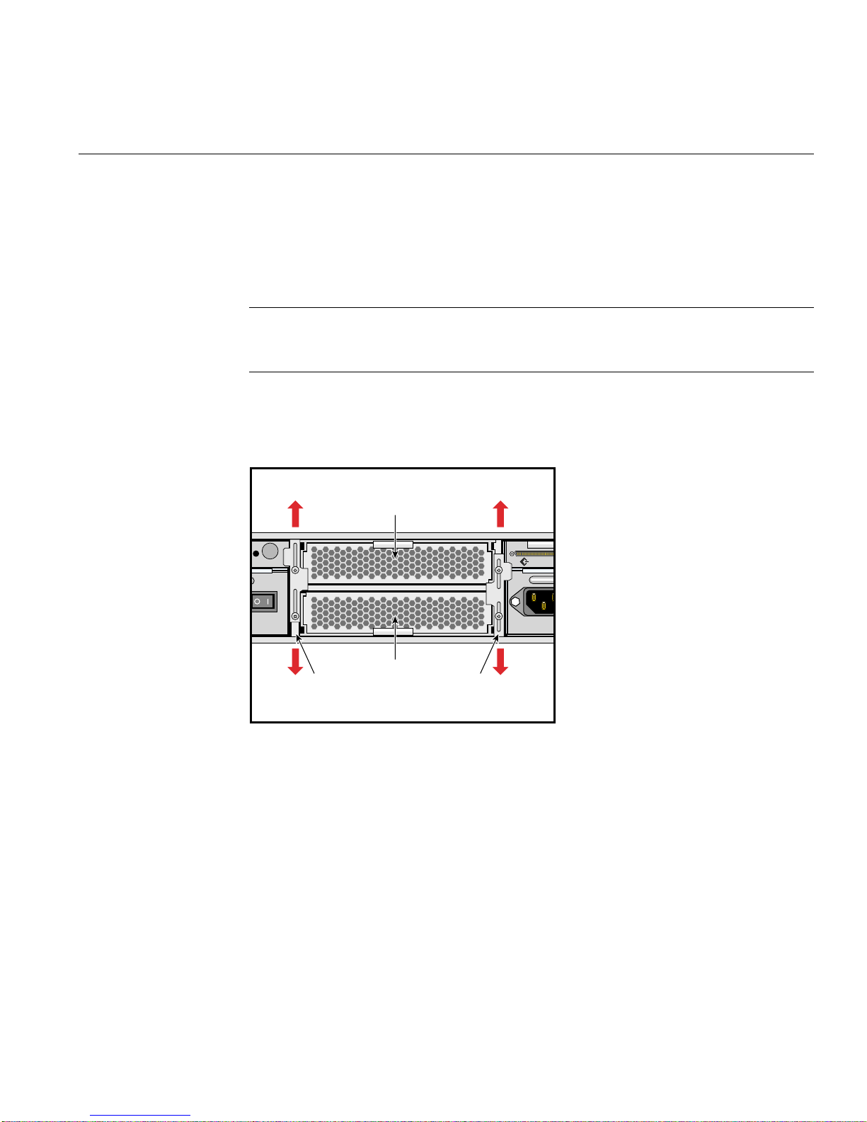
1. Loosen the screws securing both retaining brackets (see Figure 3-3), and slide the
brackets up or down, depending on the location of the cooling module to be
installed, until they are clear of the sides of the cooling module.
Replacing Cooling Modules
Cooling module
CHANNEL
Cooling module
Retaining bracket Retaining bracket
Figure 3-3 Cooling Module Retaining Bracket
2. Slide the cooling module out of the enclosure.
3. Slide the replacement cooling module fully into the enclosure. You will feel a slight
resistance as you set the cooling module connector in place and as the rear face of
the tray is flush with the rear members of the enclosure.
4. Return the retaining brackets to the center position and tighten the securing screws.
007-4428-003 35
Page 52
3: Replacing Modules
Replacing I/O Modules
Follow these steps to remove an I/O module from the SGI TP900 enclosure:
Caution: Do not remove a module unless a replacement can be immediately added. The
system must not be run without all modules in place.
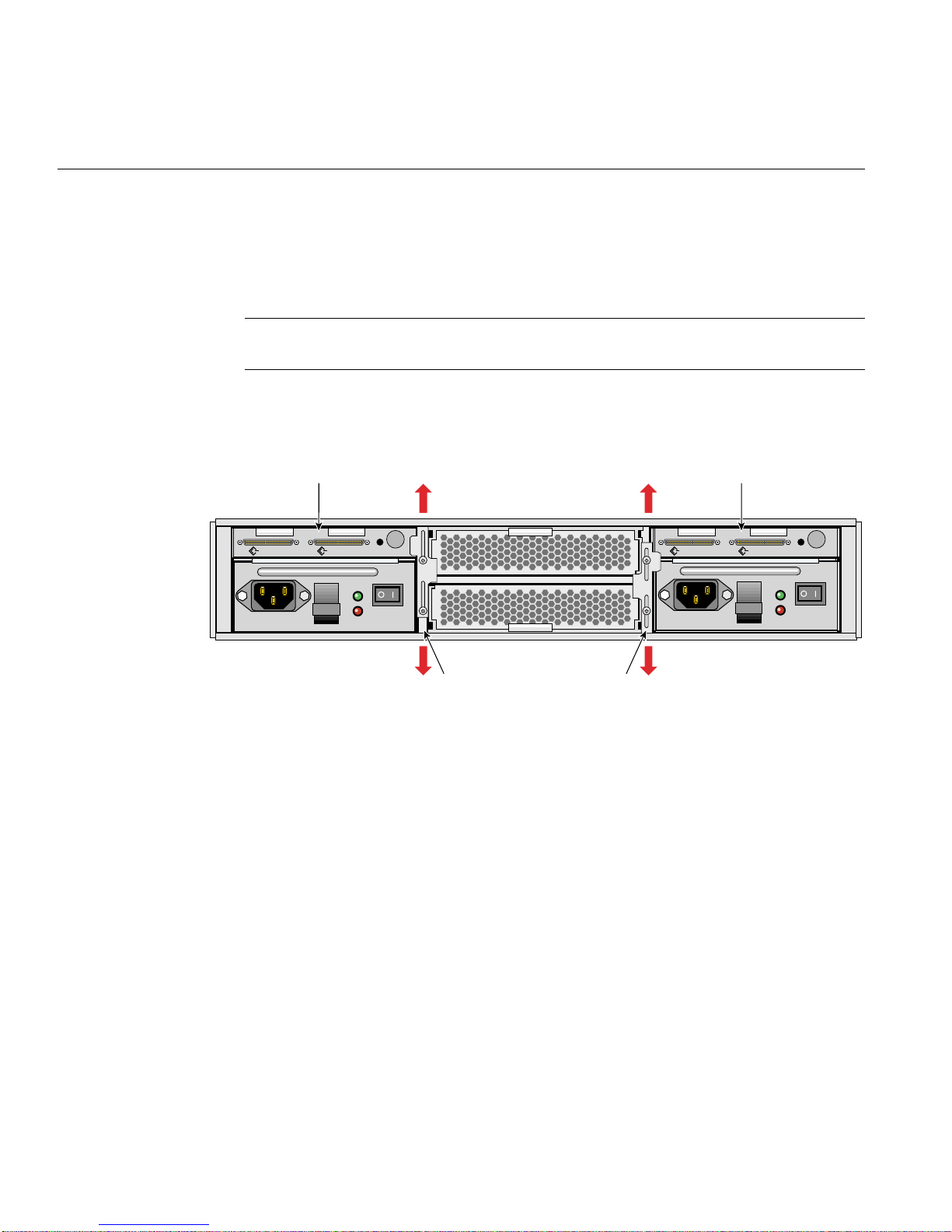
1. Loosen the screws securing the retaining bracket (see Figure 3-4) and slide the
bracket down, until it is clear of the side of the I/O module.
I/O module I/O module
CHANNEL 2 CHANNEL 1 CHANNEL 2 CHANNEL 1
OUTPUT
GOOD
FAULT
OUTPUT
GOOD
FAULT
Retaining bracket Retaining bracket
Figure 3-4 I/O Module Retaining Bracket
2. Slide the I/O module out of the enclosure.
3. Slide the replacement I/O module fully into the enclosure. You will feel a slight
resistance as you insert the card in the PCI connector and as the rear face of the I/O
module becomes flush with the rear face of the PSU.
4. Return the retaining bracket to the center position and tighten the securing screws.
36 007-4428-003
Page 53

Replacing Drive Carrier Modules
Caution: Follow electrostatic discharge (ESD) precautions while replacing the drive
carriers. Avoid contact with the backplane components and module connectors.
Follow these steps to remove and replace a drive carrier module from the SGI TP900
enclosure:
Caution: Do not remove a drive carrier unless a replacement or a dummy carrier can be
immediately added. The system must not be run without all modules in place. Any
unused drive bays must be fitted with a dummy carrier module.
1. Spin down the drive prior to removal, using the operating system.
Caution: Damage can occur to a drive if it is removed while still spinning. If you
cannot use the operating system to spin down the drives prior to removal, perform
all steps of the following procedure to ensure that the drive has stopped prior to
removal.
Replacing Drive Carrier Modules
2. Release the carrier handle by pressing the latch in the handle towards the right.
Note: The anti-tamper lock must be off. See “Engaging the Anti-tamper Locks” on
page 28 for instructions on disengaging the anti-tamper lock.
3. Gently withdraw the drive carrier module approximately 1 inch (25mm), and then
wait 30 seconds.
4. Withdraw the module from the drive bay.
007-4428-003 37
Page 54
3: Replacing Modules
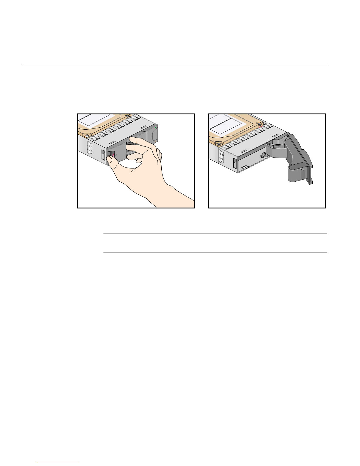
5. Release the handle of the replacement carrier by pressing the latch in the handle
towards the right, as shown in Figure 3-5. Insert the carrier into the enclosure.
Figure 3-5 Releasing the Carrier Handle
Important: Ensure that the carrier is orientated so that the drive is uppermost and
the handle opens from the left.
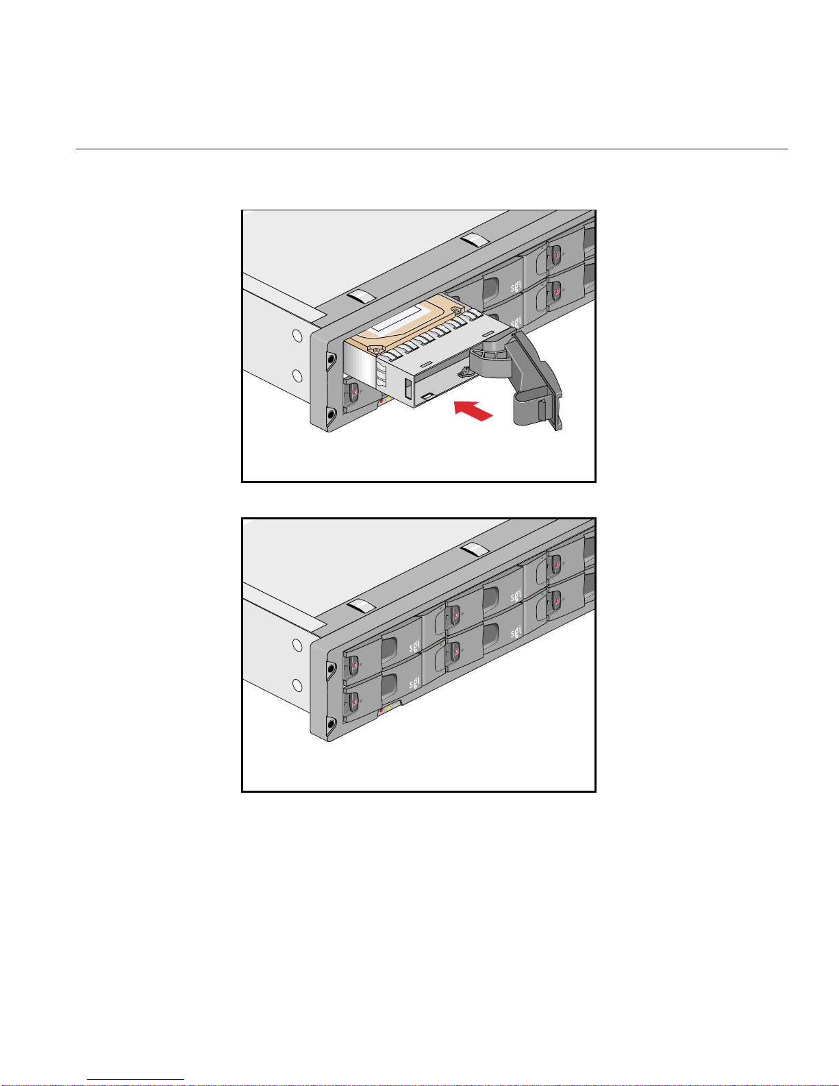
6. Gently slide the carrier all the way into the enclosure until it is stopped by the
camming lever on the right of the carrier, as shown in Figure 3-6.
38 007-4428-003
Page 55
Replacing Drive Carrier Modules
Figure 3-6 Carrier Camming Lever
7. Push the carrier handle into place—the camming foot on the base of the carrier will
engage in a slot in the enclosure. Continue to push firmly until the handle fully
engages. A click should be heard as the latch engages and holds the handle closed.
007-4428-003 39
Page 56

3: Replacing Modules
Component Part Numbers
Table 3-1 lists part numbers for the following replaceable components.
Table 3-1 Component Part Numbers
Component Part Number
Power supply module 013-3437-001
I/O module 013-3436-001
Loopback module U320 013-4187-001
Cooling module 013-3438-001
Bifurcated power cable 7260832
Dummy drive carrier 013-3439-001
Terminator U160/U320 9660121
40 007-4428-003
Page 57

Chapter 4
4. Troubleshooting
This chapter helps you identify and solve problems that might occur while you are using
the SGI TP900 storage system. The following sections are covered:
• “Overview” on page 42
• “Initial Startup Problems” on page 44
• “System Faults” on page 45
• “Power Supply Faults” on page 45
• “Cooling Module Faults” on page 46
007-4428-003 41
Page 58
4: Troubleshooting
Overview
The SGI TP900 enclosure includes a processor and associated monitoring and control
logic to enable it to diagnose problems within the enclosure’s power, cooling, and drive
systems.
All rear-mounted modules are designed to be maintained by trained technicians. Each
power supply module has a status LED.
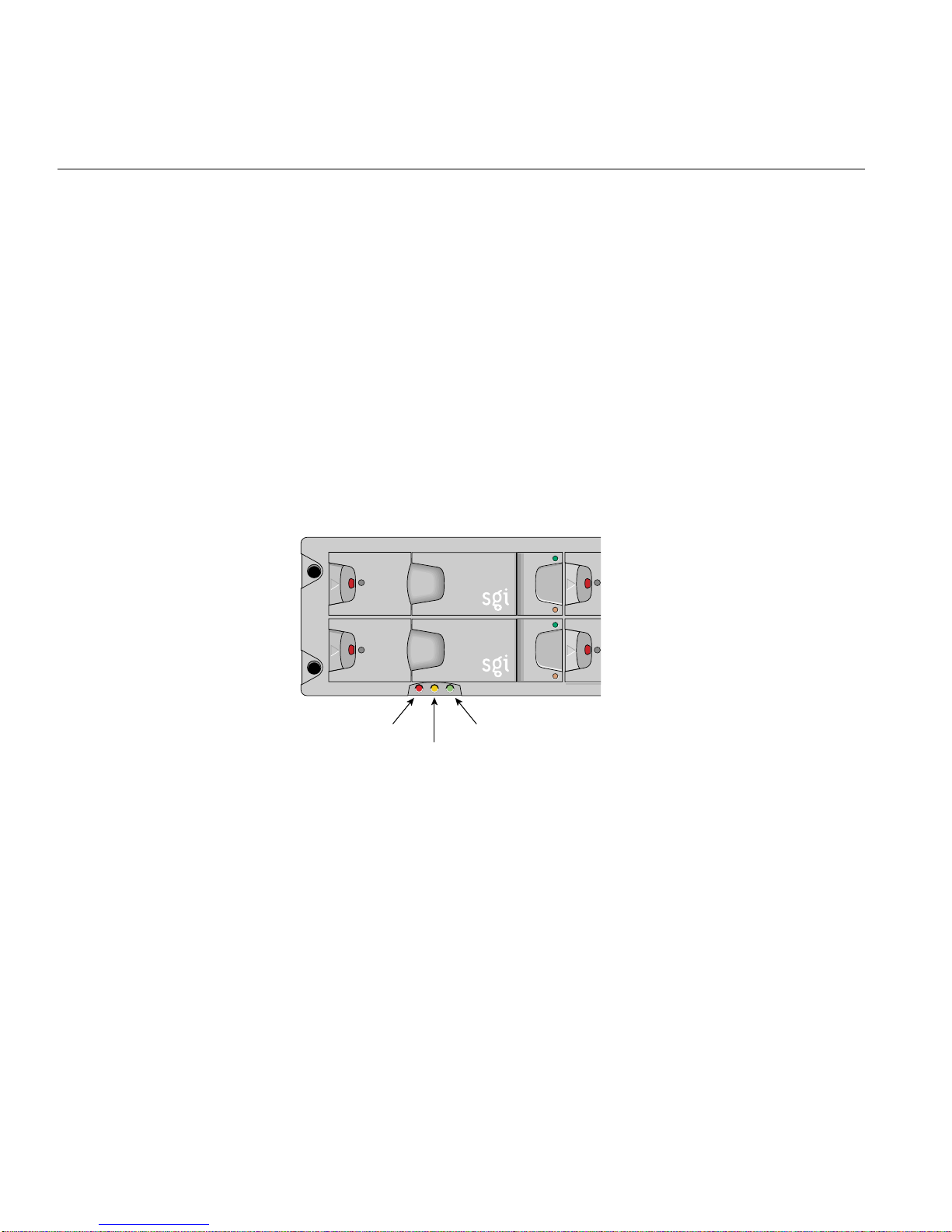
A green LED is always a positive indicator, and an amber LED indicates that there is a
critical fault within the module. The ESI/Ops panel displays the aggregated status of all
the modules. The ESI/Ops panel LEDs are shown in Figure 4-1.
System status Cooling status
Power status
Figure 4-1 ESI/Ops Panel LEDs
42 007-4428-003
Page 59

Overview
Table 4-1 summarizes the functions of the LEDs on the ESI/Ops panel and refers to the
sections that cover specific component failures.
Table 4-1 ESI/Ops LED States
LED LED State and Meaning See This Section
System
status
Power
status
Cooling
status
Green signifies that power is applied to the enclosure.
Amber signifies that the ESI processor has failed.
Green signifies that the power supplies are functioning normally.
Amber signifies that there is a PSU failure in a dual-PSU enclosure.
In the event of a PSU failure in a single-PSU enclosure, all LEDs are off.
Green signifies that all fans are functioning normally.
Amber signifies that there is a fan failure.
“System Faults”
on page 45
“Power Supply
Faults” on
page 45
“Cooling
Module Faults”
on page 46
The following sections explain how to troubleshoot initial startup problems, system
faults, power supply faults, and cooling module faults.
007-4428-003 43
Page 60

4: Troubleshooting
Initial Startup Problems
Check that you have wired the subsystem correctly. Call your supplier for a replacement
part if:
• Cords are missing or damaged.
• Plugs are of the wrong type.
• Cords are too short.
Use the following checklist if your computer does not recognize the SGI TP900 system:
• Check that the Ultra-3 SCSI interface cables from the enclosure to the host computer
are fitted correctly.
• Check the SCSI ID settings on your system host.
• Check that the LEDs on all installed drive carrier modules are illuminated green.
Note that the drive LEDs will not be lit during drive spinup.
• Check that all drive carrier modules have been correctly installed.
• Check the I/O module setup as follows:
– Check that the I/O module has been correctly installed and all external links
and cables are securely fitted.
– Check that the maximum cable length has not been exceeded; the maximum
cable length is 10m for U160 and 3m for U320.
– Check that the correct termination is fitted on all unused ports.
– Check that different IDs have been selected for all devices on a channel.
44 007-4428-003
Page 61

System Faults
System Faults
Table 4-2 explains how to troubleshoot a system status LED that is amber.
Table 4-2 System Faults
Symptom Cause Action
The system
LED is amber.
Power Supply Faults
Table 4-3 explains how to troubleshoot a power supply module status LED that is amber.
Table 4-3 Power Supply Faults
Symptom Cause Action
Operator panel power
supply LED is amber.
OR
One or more power
supply module LEDs
are amber.
The ESI processor has
detected an internal
fault.
Any power
fault.
1. Check for other amber LED indicators on the power
supply modules. If there is a PSU error, there may be a
communications problem with that power supply
module. Remove and then re-fit the module. If the
problem persists, change the module.
2. Check for other amber LED indicators on the drive
carriers. If none are evident, there may be either an ESI
processor problem or a backplane problem.
1. Check that the AC power connection to the power
supply module is live.
2. Check that the power supply module is switched on.
3. Disconnect the power supply module from AC
power, remove the module from the system, and then
re-install it. If the problem persists, replace the power
supply module.
007-4428-003 45
Page 62

4: Troubleshooting
Cooling Module Faults
Table 4-4 explains how to troubleshoot a cooling module status LED that is amber.
Table 4-4 Cooling Module Faults
Symptom Cause Action
Operator panel cooling
LED is amber.
One or more fans
within the cooling
modules have failed
Remove the module(s)fromthesystem, and then
re-install it. Ifproblem persists, replace thefaulty
cooling module.
46 007-4428-003
Page 63

Appendix A
A. Technical Specifications
This appendix lists technical specifications of the SGI TP900 storage system in these
sections:
• “Physical and Environmental Specifications” on page 48
• “Power Requirements” on page 49
007-4428-003 47
Page 64

A: Technical Specifications
Physical and Environmental Specifications
Table A-1 shows the physical and environmental specifications for the SGI TP900 storage
system.
Table A-1 Physical and Environmental Specifications
Height 85.7 mm (3.37 in.)
Width 447 mm (17.6 in.)
Depth 545 mm (21.46 in.)
Weight Maximum configuration: 22 Kg (48.5 lb)
Empty enclosure: 6.5 Kg (14.3 lb)
Power supply module: 1.75 Kg (3.85 lb)
Cooling module: 1 Kg (2.2 lb)
I/O module: 1.25 Kg (2.75 lb)
Temperature,
operating
Temperature,
non-operating
Temperature,
shipping
Humidity 20% to 80% non-condensing (operating)
Altitude,
operating
Altitude,
non-operating
+10 ºC (+50 ºF) to +35 ºC (+95 ºF) (single-cooling module)
+10 ºC (+50 ºF) to +40 ºC (+104 ºF) (dual-cooling module)
+0 ºC (+32 ºF) to +50 ºC (+122 ºF)
-40 ºC (-40 ºF) to +60 ºC (+140 ºF)
8% to 80% non-condensing (non-operating)
5% to 100% condensing but not precipitating (shipping)
0 to 2133 m (0 to 7000 ft.)
10,000 ft. at maximum ambient temperature of +35 ºC
-305 to 12,192 m (-1,000 to 40,000 ft.)
48 007-4428-003
Page 65

Power Requirements
Table A-2 lists the minimum power requirements for the SGI TP900 storage system.
Table A-2 Minimum Power Requirements
Factor Requirement
Voltage 110/220 VAC auto-sensing worldwide
Frequency 50/60 Hz
Maximum power consumption 350 W maximum continuous
Power Requirements
007-4428-003 49
Page 66

Page 67

Appendix B
B. Regulatory Information
This section contains Class B warnings and specifications. The SGI TP900 rackmountable
storage system conforms to several national and international specifications and
European Directives listed in “Manufacturer’s Declaration of Conformity”.
Caution: The SGI TP900 storage system has several governmental and third-party
approvals, licenses, and permits. Do not modify this product in any way that is not
expressly approved by SGI. If you do, you may lose these approvals and your
governmental agency authority to operate this device.
Manufacturer’s Declaration of Conformity
A “Manufacturer’s Declaration of Conformity” is available on the Web. Look at your
system (regulatory) label on the rear of your workstation to determine your CMN
(model) number, which you need to identify your Declaration of Conformity, and to find
the series number of your processor.
To locate the information on the Web, enter the following URL:
http://www.sgi.com/compliance/index.html
007-4428-003 51
Page 68

B: Regulatory Information
FCC Class B Conformance
This equipment complies with Part 15 of the FCC Rules. Operation is subject to the
following two conditions:
• This device may not cause harmful interference.
• This device must accept any interference received, including interference that may
cause undesired operation.
This equipment has been tested and found to comply with the limits for a Class B digital
device, pursuant to Part 15 of the FCC Rules. These limits are designed to provide
reasonable protection against harmful interference in a residential installation. This
equipment generates, uses and can radiate radio frequency energy and, if not installed
and used in accordance with the instructions, may cause harmful interference to radio
communications. However, there is no guarantee that interference will not occur in a
particular installation. If this equipment does cause harmful interference to radio or
television reception, which can be determined by turning the equipment off and on, you
are is encouraged to try to correct the interference by using one or more of the following
measures:
• Reorient or relocate the receiving antenna.
• Increase the separation between the equipment and receiver.
• Connect the equipment into an outlet on a circuit different from that to which the
receiver is connected.
• Consult the dealer or an experienced radio/TV technician for help.
Industry Canada Notice (Canada Only)
Cet appareil numérique n’émet pas de perturbations radioélectriques dépassant les
normes applicables aux appareils numériques de Classe B préscrites dans le Règlement
sur les interferences radioélectriques établi par le Ministère des Communications du
Canada.
52 007-4428-003
Page 69
CE Notice
Marking by the “CE” symbol indicates compliance of the device to directives of the
European Community. A “Declaration of Conformity” in accordance with the above
standards has been made and is available from SGI upon request.
VCCI Notice (Japan Only)
CE Notice
Korean Regulatory Notice
007-4428-003 53
Page 70

B: Regulatory Information
Shielded Cables
The SGI TP900 storage system is FCC-compliant under test conditions that include the
use of shielded cables between the storage system and a host. Shielded cables reduce the
possibility of interference with radio, television, and other devices. If you use any cables
that are not from SGI, make sure they are shielded. Telephone cables do not need to be
shielded.
Electrostatic Discharge
SGI designs and tests its products to be immune to the effects of electrostatic discharge
(ESD). ESD is a source of electromagnetic interference and can cause problems ranging
from data errors and lockups to permanent component damage.
While operating the SGI TP900 storage system, it is important that you keep all the
covers, doors, and dummy (filler) panels in place. The shielded cables that came with the
product should be installed correctly.
Electromagnetic Emissions
This device complies with the Class B limits of Part 15 of the FCC Rules. Operation is
subject to the following two conditions:
• This device may not cause harmful interference.
• This device must accept any interference received, including interference that may
cause undesired operation.
Also, this device complies with Class B electromagnetic emissions limits of C.I.S.P.R.
Publication 22, Limits and Methods of Measurement of Radio Interference
Characteristics of Information Technology Equipment.
54 007-4428-003
Page 71

Index
A
airflow, 3, 16
anti-tamper lock, 8
B
bay numbering
drive bay, 17
enclosure, 17
rear bay, 18
blank module, 16
C
cables, shielded, 54
Class B, 51-54
components, part numbers, 40
cooling module, 14
customer service, xiv
E
electromagnetic emissions, 54
electrostatic discharge, 54
enclosure
bay numbering, 17
chassis, 2
height, 2
Enclosure System Interface/Operators (ESI/Ops)
panel, 4
ESI/Ops panel, 4
G
grounding checks, 20
H
humidity requirements, 48
D
documentation
IRIS InSight Library, xiv
related, xiv
Technical Publications Library, xiv
drive carrier module, 6
dummy carrier module, 16
007-4428-003 55
I
input/output module, 12
I/O module, 12
L
LED status
Page 72

Index
drive carrier, 7
ESI/Ops panel, 4
power supply module, 11
M
manuals, related, xiv
model number, 51
module
blank, 16
cooling, 14
drive carrier, 6
dummy carrier, 16
input/output, 12
I/O, 12
power supply, 10
PSU, 10
N
numbering convention, modules, 17
S
SCSI_ID addressing, 24
service, xiv
SGI, contacting
shielded cables
, xiv
, 54
slot numbering
drive bay, 17
enclosure, 17
rear bay, 18
support, xiv
T
temperature requirements, 48
V
voltage, 49
P
part numbers, 40
physical specifications, 48
power requirements, 49
power supply module, 10
PSU, 10
R
regulatory information, 51-54
56 007-4428-003
 Loading...