


SGI® Total Performance 9300
RAID User’s Guide
007-4644-001

CONTRIBUTORS
Written by Matt Hoy
Illustrated by Kelly Begley, Matt Hoy, and Jim Ostrom
Production by Karen Jacobson
Engineering contributions by Bill Andrews, Marty Castilla, Bill Lusche, Robert Novak,
COPYRIGHT
© 2003, Silicon Graphics, Inc. All rights reserved; provided portions may be copyright in third parties, as indicated elsewhere herein. No
permission is granted to copy, distribute, or create derivative works from the contents of this electronic documentation in any manner, in whole
or in part, without the prior written permission of Silicon Graphics, Inc.
LIMITED RIGHTS LEGEND
Use, duplication, or disclosure by the Government is subject to restrictions as set forth in the Rights in Data clause at FAR 52.227-14 and/or in
similar orsuccessor clauses inthe FAR, orin the DOD,DOE or NASAFAR Supplements. Unpublishedrights reserved under the Copyright Laws
of the United States. Contractor/manufacturer is Silicon Graphics, Inc., 1600 Amphitheatre Pkwy., Mountain View, CA 94043-1351.
TRADEMARKS AND ATTRIBUTIONS
Silicon Graphics, SGI, the SGI logo, IRIX, and Origin are registered trademarks, and Altix, CXFS, FailSafe, Octane2, and Silicon Graphics Fuel
are trademarks, of Silicon Graphics, Inc., in the United States and.or other countries worldwide.
Brocade and Silkworm are registered trademarks of Brocade Communications Systems, Inc.
QLogic is a trademark of QLogic Corporation.
Cover design by Sarah Bolles, Sarah Bolles Design, and Dany Galgani, SGI Technical Publications
Henry Ortiz, and Sammy Wilborn

Record of Revision
Version Description
001 May 2003
Original publication
007-4644-001 iii


Contents
Record of Revision . . . . . . . . . . . . . . . . . . . . . . iii
Figures . . . . . . . . . . . . . . . . . . . . . . . . . . ix
Tables . . . . . . . . . . . . . . . . . . . . . . . . . . xi
About This Guide. . . . . . . . . . . . . . . . . . . . . . .xiii
Important Information . . . . . . . . . . . . . . . . . . . . .xiii
Chapter Descriptions . . . . . . . . . . . . . . . . . . . . . . xiv
Related Publications . . . . . . . . . . . . . . . . . . . . . . xv
Conventions . . . . . . . . . . . . . . . . . . . . . . . xvii
Product Support . . . . . . . . . . . . . . . . . . . . . . xvii
Reader Comments . . . . . . . . . . . . . . . . . . . . . . xviii
1. Introduction to the SGI TP9300 . . . . . . . . . . . . . . . . . . . 1
System Features . . . . . . . . . . . . . . . . . . . . . . . 1
Performance Features . . . . . . . . . . . . . . . . . . . . 2
RAID Controller Features . . . . . . . . . . . . . . . . . . . 3
Availability Features . . . . . . . . . . . . . . . . . . . . . 4
Supported Platforms . . . . . . . . . . . . . . . . . . . . . 4
Adapter and Switch Compatibility . . . . . . . . . . . . . . . . . 5
System Components . . . . . . . . . . . . . . . . . . . . . . 5
Storage Enclosures . . . . . . . . . . . . . . . . . . . . . 6
TP9300 Rack . . . . . . . . . . . . . . . . . . . . . . . 8
2. Storage Enclosures . . . . . . . . . . . . . . . . . . . . . . 11
Overview . . . . . . . . . . . . . . . . . . . . . . . . . 12
Disk Drives . . . . . . . . . . . . . . . . . . . . . . . . . 16
RAID Controllers . . . . . . . . . . . . . . . . . . . . . . . 17
Environmental Status Modules (ESMs) . . . . . . . . . . . . . . . . . 19
007-4644-001 v

Contents
Fans . . . . . . . . . . . . . . . . . . . . . . . . . . . 20
Power Supplies . . . . . . . . . . . . . . . . . . . . . . . . 21
Tray ID Switch . . . . . . . . . . . . . . . . . . . . . . . . 23
Link Rate Switch . . . . . . . . . . . . . . . . . . . . . . . 24
SFP Transceivers . . . . . . . . . . . . . . . . . . . . . . . 25
3. Operating Storage Enclosures . . . . . . . . . . . . . . . . . . . 27
Turning the Power On . . . . . . . . . . . . . . . . . . . . . . 27
Turning the Power On after an Unexpected Shutdown . . . . . . . . . . . . 29
Troubleshooting an Overtemp Condition . . . . . . . . . . . . . . . 29
Turning the Power On after an Overtemp Shutdown . . . . . . . . . . . . 30
Turning the Power On after an Emergency Shutdown . . . . . . . . . . . 31
Turning the Power Off . . . . . . . . . . . . . . . . . . . . . . 32
Monitoring Status with Software . . . . . . . . . . . . . . . . . . . 33
Checking the Indicator Lights. . . . . . . . . . . . . . . . . . . . 34
Front Indicator Lights . . . . . . . . . . . . . . . . . . . . . 34
Rear Indicator Lights . . . . . . . . . . . . . . . . . . . . . 36
Moving the Enclosure . . . . . . . . . . . . . . . . . . . . . . 40
Removing the Enclosure . . . . . . . . . . . . . . . . . . . . 40
Reinstalling the Enclosure . . . . . . . . . . . . . . . . . . . 43
4. Replacing Enclosure Components . . . . . . . . . . . . . . . . . . 45
Replacing a Failed Disk Drive. . . . . . . . . . . . . . . . . . . . 45
Replacing a Failed Fan . . . . . . . . . . . . . . . . . . . . . . 48
Replacing a Failed Power Supply Module . . . . . . . . . . . . . . . . 50
Replacing a Failed SFP Transceiver . . . . . . . . . . . . . . . . . . 52
Replacing a Failed RAID Controller Module . . . . . . . . . . . . . . . 54
Replacing a Failed Environmental Status Module . . . . . . . . . . . . . . 56
Upgrading Drives . . . . . . . . . . . . . . . . . . . . . . . 59
Adding a Drive to an Empty Slot . . . . . . . . . . . . . . . . . 59
Adding Drives of Larger Capacity . . . . . . . . . . . . . . . . . 61
Adding Expansion Enclosures . . . . . . . . . . . . . . . . . . . 63
5. Cabling . . . . . . . . . . . . . . . . . . . . . . . . . . 65
Connecting the Drive Loop Cables . . . . . . . . . . . . . . . . . . 65
vi 007-4644-001

Contents
Connecting the System to the Hosts . . . . . . . . . . . . . . . . . . 69
Examples of Direct Host Connection Cabling . . . . . . . . . . . . . . 69
Examples of Fabric/Switch Host Connection Cabling . . . . . . . . . . . 72
Connecting Ethernet and Serial Cables for Array Management. . . . . . . . . 73
Powering On the System . . . . . . . . . . . . . . . . . . . . . 75
A. Specifications and Requirements . . . . . . . . . . . . . . . . . . 79
Rack Specifications . . . . . . . . . . . . . . . . . . . . . . 79
Dimensions . . . . . . . . . . . . . . . . . . . . . . . 81
Weight . . . . . . . . . . . . . . . . . . . . . . . . . 82
Area Requirements . . . . . . . . . . . . . . . . . . . . . 84
Wiring and Power . . . . . . . . . . . . . . . . . . . . . 85
Environmental . . . . . . . . . . . . . . . . . . . . . . 90
Enclosure Specifications . . . . . . . . . . . . . . . . . . . . . 91
Dimensions . . . . . . . . . . . . . . . . . . . . . . . 91
Weights . . . . . . . . . . . . . . . . . . . . . . . . 92
Wiring and Power . . . . . . . . . . . . . . . . . . . . . 93
Environmental . . . . . . . . . . . . . . . . . . . . . . 94
Air Flow . . . . . . . . . . . . . . . . . . . . . . . . 95
B. SGI Field Engineering Compliance Statements . . . . . . . . . . . . . . 97
Electromagnetic Emissions . . . . . . . . . . . . . . . . . . . . 97
Radio and Television Interference . . . . . . . . . . . . . . . . . . 97
Product Safety . . . . . . . . . . . . . . . . . . . . . . . . 98
Electrostatic Discharge . . . . . . . . . . . . . . . . . . . . . 98
Shielded Cables . . . . . . . . . . . . . . . . . . . . . . . 99
FCC Warning . . . . . . . . . . . . . . . . . . . . . . . . 99
VDE 0871/6.78 . . . . . . . . . . . . . . . . . . . . . . . .100
European Union Statement . . . . . . . . . . . . . . . . . . . .100
International Special Committee on Radio Interference (CISPR). . . . . . . . . .101
Canadian Department of Communications Statement . . . . . . . . . . . .101
Attention . . . . . . . . . . . . . . . . . . . . . . . . .101
Japanese Class A Compliance Statement . . . . . . . . . . . . . . . .101
007-4644-001 vii


Figures
Figure 1-1 TP9300 Tower and Rackmount Storage Enclosures (Front View). . 6
Figure 1-2 TP9300 Controller and Expansion Enclosures (Rear View) . . . 7
Figure 1-3 TP9300 Rack with Enclosures Installed . . . . . . . . . 9
Figure 1-4 Rack Features . . . . . . . . . . . . . . . . 10
Figure 2-1 Storage Enclosure Components (Front View) . . . . . . . 13
Figure 2-2 Storage Enclosure Components (Rear View) . . . . . . . 15
Figure 2-3 Disk Drives and Drive Bay Numbering . . . . . . . . . 16
Figure 2-4 2882 RAID Controller . . . . . . . . . . . . . . 18
Figure 2-5 Environmental Status Modules . . . . . . . . . . . 19
Figure 2-6 Fan Units . . . . . . . . . . . . . . . . . 20
Figure 2-7 Power Supplies . . . . . . . . . . . . . . . . 22
Figure 2-8 Tray ID Switch . . . . . . . . . . . . . . . . 23
Figure 2-9 Link Rate Switch . . . . . . . . . . . . . . . 24
Figure 2-10 SFP Transceiver. . . . . . . . . . . . . . . . 25
Figure 3-1 Turning the Power On and Off . . . . . . . . . . . 28
Figure 3-2 Storage Enclosure Front Indicator Lights . . . . . . . . 35
Figure 3-3 Storage Enclosure Rear Indicator Lights . . . . . . . . . 37
Figure 3-4 Removing the Side Brackets from the Enclosure . . . . . . 41
Figure 3-5 Removing the Empty Drive Enclosure . . . . . . . . . 42
Figure 4-1 Removing and Installing a Drive Module . . . . . . . . 46
Figure 4-2 Removing and Installing a Fan Module . . . . . . . . . 49
Figure 4-3 Fault Lights for Fan Module Replacement . . . . . . . . 49
Figure 4-4 Removing and Installing a Power Supply Module . . . . . . 51
Figure 4-5 Removing and Installing an SFP Transceiver . . . . . . . 53
Figure 4-6 Removing and Installing a RAID Controller Module . . . . . 55
Figure 4-7 Removing SFPs from the Environmental Status Module . . . . 57
Figure 4-8 Removing and Installing an Environmental Status Module . . . 58
Figure 4-9 Adding New Expansion Enclosures to an Existing Array . . . . 64
007-4644-001 ix

Figures
Figure 5-1 Drive Loop Cabling for Systems with Two Enclosures . . . . . 66
Figure 5-2 Drive Loop Cabling for Systems with Three or More Enclosures . . 67
Figure 5-3 Drive Loop Cabling for Systems with Eight Enclosures . . . . 68
Figure 5-4 Direct Host Connection with Failover . . . . . . . . . 70
Figure 5-5 Direct Host Connection without Failover . . . . . . . . 71
Figure 5-6 Connecting to Hosts via a Fibre Channel Switch . . . . . . 72
Figure 5-7 Connecting Ethernet Cables . . . . . . . . . . . . 74
Figure 5-8 Power Connections and Switches of the Enclosures . . . . . 75
Figure 5-9 PDU Cabling. . . . . . . . . . . . . . . . . 76
Figure A-1 Populated Rack . . . . . . . . . . . . . . . . 80
Figure A-2 Dimensions of the System Rack . . . . . . . . . . . 81
Figure A-3 Rack Weights . . . . . . . . . . . . . . . . 83
Figure A-4 System Area Requirements . . . . . . . . . . . . 84
Figure A-5 Power Connections to Controller and Expansion Enclosures . . . 87
Figure A-6 AC Power Connectors and Receptacles . . . . . . . . . 89
Figure A-7 Dimensions of the System Enclosure . . . . . . . . . . 91
Figure A-8 Air Flow in the System Enclosure . . . . . . . . . . . 95
x 007-4644-001

Tables
Table 3-1 Storage Enclosure Front Indicator Lights . . . . . . . . 36
Table 3-2 Storage Enclosure Rear Indicator Lights . . . . . . . . . 38
Table A-1 Rack, Crate, and Enclosure Weights . . . . . . . . . . 82
Table A-2 AC Power Requirements (Domestic and International) . . . . 86
Table A-3 Environmental Requirements . . . . . . . . . . . . 90
Table A-4 Enclosure Weights . . . . . . . . . . . . . . . 92
Table A-5 Enclosure Module Weights . . . . . . . . . . . . 92
Table A-6 Site Wiring Voltages for System Enclosures
(Single-phase Line-to-neutral) . . . . . . . . . . . 93
Table A-7 Altitude Requirements for System Enclosures . . . . . . . 94
Table A-8 Environmental Requirements for System Enclosures . . . . . 94
007-4644-001 xi


About This Guide
This guide provides an overview of the SGI Total Performance 9300 (SGI TP9300). It
covers routine operation and replacement procedures and provides troubleshooting and
reference information for all customer-replaceable components.
The SGI TP9300 is a highly scalable RAID storage system designed for continuous
availability. Some of the features of the system include hot-swappable components, easy
expansion, and redundant power and cooling systems.
This guide is intended for system operators and service technicians who have extensive
knowledge of Fibre Channel network technology and computer system operation,
maintenance, and repair.
Use this guide to learn about all of the following:
• The parts of your system: the rack, controller enclosures, and expansion enclosures
• Operating your system correctly
• Replacing failed components
Important Information
Danger: Never look into the end of a fiber-optic cable to confirm that light is being
emitted (or for any other reason). Most fiber-optic laser wavelengths (1300 nmand
1550nm) are invisible to the eye and cause permanent eye damage. Shorterwavelength
lasers (for example, 780 nm) are visible and can cause significant eye damage. Use only
an optical power meter to verify light output.
007-4644-001 xiii

About This Guide
Danger: Never look into the end of a fiber-optic cable on a powered device with any
type of magnifying device, such as a microscope, eye loupe, or magnifying glass. Such
activity causes a permanent burn on the retina of the eye. Optical signals cannot be
verified by looking into the fiber end.
Chapter Descriptions
This guide contains the following chapters:
• Chapter 1, “Introduction to the SGI TP9300,” describes the features and components
• Chapter 2, “Storage Enclosures,” gives a detailed overview of the system enclosure
• Chapter 3, “Operating Storage Enclosures,” describes the functions and basic
of the system.
and its components.
operation of the system enclosures, including power on and troubleshooting with
the indicator lights.
• Chapter 4, “Replacing Enclosure Components,” gives detailed procedures for
replacing failed components.
• Chapter 5, “Cabling,” describes cabling between controller and expansion
enclosures and between controllers and hosts.
• Appendix A, “Specifications and Requirements,” describes component
specifications and requirements for purposes of installation and maintenance.
• Appendix B, “SGI Field Engineering Compliance Statements,” describes the
regulatory and compliance information for the system.
xiv 007-4644-001

Related Publications
This guide is part of a document set that fully supports the installation, operation, and
service of the TP9300. See the following documents for more information about your
system. If a document number ends in “X,” use the latest available version of that
document.
• SGI TP9300 RAID Installation and Upgrade Guide (108-0401-00x)
• SGI TP9400 and TP9500 RAID IRIX Administration Guide(007-4306-00x)
• SGI TP9400 and SGI TP9500 Software Concepts Guide (007-4305-00x)
• SGI Storage Area Network Installation Instructions (108-0252-00x)
About This Guide
This guide gives complete instructions on how to unpack, install, and configure the
SGI TP9300 and its components. It also contains upgrade information.
This guide gives complete instructions on how to install the TPSSM software for
host and/or client operation.
This guide explains the terminology and features of the TPSSM storage
management software.
This guide is included with the Fibre Channel switch and provides information on
storage area network installation and topologies.
You can obtain SGI documentation, release notes, or man pages in the following ways:
• See the SGI Technical Publications Library at http://docs.sgi.com. Various formats
are available. This library contains the most recent and most comprehensive set of
online books, release notes, man pages, and other information.
• If it is installed on your SGI system, you can use InfoSearch, an online tool that
provides a more limited set of online books, release notes, and man pages. With an
IRIX system, select Help from the Toolchest, and then select InfoSearch. Or you can
type infosearch on a command line.
• You can also view release notes by typing either grelnotes or relnotes on a
command line.
• You can also view man pages by typing man <title> on a command line.
007-4644-001 xv

About This Guide
SGI systems include a set of IRIX man pages, formatted in the standard UNIX “man
page” style. These are found online on the internal system disk (or CD-ROM) and are
displayed using the man command. For example, to display the man page for the
Add_disk command, type the following on a command line:
man Add_disk
Important system configuration files and commands are documented on man pages.
References in the documentation to these pages include the name of the command and
the section number in which the command is found. For example, “Add_disk(1)” refers
to the Add_disk command and indicates that it is found in section 1 of the IRIX
reference.
For additional information about displaying reference pages using the man command,
see man(1).
In addition, the apropos command locatesman pages based on keywords. For example,
to display a list of man pages that describe disks, type the following on a command line:
apropos disk
For information about setting up and using apropos, see apropos(1) and
makewhatis(1M).
xvi 007-4644-001

Conventions
About This Guide
The following conventions are used throughout this document:
Convention Meaning
Command This fixed-space font denotes literal items such as commands, files,
routines, path names,signals, messages, and programming language
structures.
variable The italic typeface denotes variable entries and words or concepts
being defined. Italic typeface also is used for book titles.
user input This fixed-space font denotes literal items that the user enters in
interactive sessions. Output is shown in nonbold, fixed-space font.
[ ] Brackets enclose optional portions of a command or directive line.
... Ellipses indicate that a preceding element can be repeated.
man page(x) Man page section identifiers appear in parentheses after man page
names.
GUI element This font denotes the names of graphical user interface (GUI)
elements such as windows, screens, dialog boxes, menus, toolbars,
icons, buttons, boxes, fields, and lists.
Product Support
SGI provides a comprehensive product support and maintenance program for its
products:
• If you are in North America, contact the Technical Assistance Center at
+1 800 800 4SGI or contact your authorized service provider.
• If you are outside North America, contact the SGI subsidiary or authorized
distributor in your country.
007-4644-001 xvii

About This Guide
Reader Comments
If you have comments about the technical accuracy, content, or organization of this
document, contact SGI. Be sure to include the title and document number of the manual
with your comments. (Online, the document number is located in the front matter of the
manual. In printed manuals, the document number is located at the bottom of each
page.)
You can contact SGI in any of the following ways:
• Send e-mail to the following address:
techpubs@sgi.com
• Use the Feedback option on the Technical Publications Library website:
http://docs.sgi.com
• Contact your customer service representative and ask that an incident be filed in the
SGI incident tracking system.
• Send mail to the following address:
Technical Publications
SGI
1600 Amphitheatre Pkwy., M/S 535
Mountain View, California 94043-1351
• Send a fax to the attention of “Technical Publications” at +1 650 932 0801.
SGI values your comments and will respond to them promptly.
xviii 007-4644-001

1. Introduction to the SGI TP9300
System Features
Chapter 1
The SGI Total Performance 9300 is a high-bandwidth RAID Fibre Channel storage
system. This chapter gives a brief overview of the features of the TP9300 and its primary
components in the following sections:
• “System Features” on page 1
• “System Components” on page 5
The features of the TP9300 are listed in the following sections:
• “Performance Features” on page 2
• “RAID Controller Features” on page 3
• “Availability Features” on page 4
• “Supported Platforms” on page 4
• “Adapter and Switch Compatibility” on page 5
007-4644-001 1

1: Introduction to the SGI TP9300
Performance Features
The SGI TP9300 RAID storage system has the following basic features:
• Outstanding performance, built on multi-channel end-to-end Fibre Channel
• Continuous availability, with constant monitoring and optional redundancy of all
• Dynamic scalability, making it easy to grow all subsystem resources without
• Superior connectivity, allowing simultaneous connections to multiple servers
• Vast storage capacity with support for large numbers of drives.
• Storage management facilities for installation, configuration, expansion, and
• Redundant power supplies and hot-swappable components.
technology.
active components.
disruption.
directly or by way of storage area networks (SANs). Support for optical host
connections.
monitoring.
• Easily upgradeable to meet a variety of performance requirements.
• Integrated RAID controllers.
• Battery backup for cache data.
Note: JBOD is not supported.
2 007-4644-001

RAID Controller Features
The RAID controllers in the TP9300 have the following features:
• 112-drive maximum configuration
• 4 RAID levels (0, 1, 3, and 5)
• 2 Gbit/s front end (FE) and back end (BE) Fibre Channel arbitrated loop (FC-AL)
• Immediate LUN availability (ILA)
• Transparent disk drive rebuilds
• Variable stripe size per controller (16K, 32K, and 64K)
• Mirrored cache
• Drive roaming during power off
• Cache coherency
• Transparent failover and failback
• Automatic error recovery
System Features
• Write through, write back, or read ahead support
• Automatic detection of failed drives
• Automatic drive rebuilds, using “hot spare” drive
• Hot-swappable drives
• SAN mapping server to LUN mapping
• Automatic firmware flashing: In a dual controller configuration, the firmware of the
replacement controller is automatically flashed to match the firmware of the
surviving controller.
007-4644-001 3

1: Introduction to the SGI TP9300
Availability Features
The TP9300 has the following availability features:
• Dual power feeds with dual power supplies
• Redundant cooling
• Battery back-up (BBU) maintains cache in case of power failure
• IRIX path failover
• Dynamic hot-sparing
• Non-disruptive component replacement
• Enclosure services interface (ESI) for SCSI enclosure services (SES)
Supported Platforms
The TP9300 supports the following hardware and software platforms:
• Software: IRIX, CXFS, FailSafe
• Hardware: SGI Altix 3000, SGI Origin 200, Origin 300, Onyx 300, Origin 2000,
Origin 3000 series, and Onyx 3000 series servers.
4 007-4644-001

Adapter and Switch Compatibility
The TP9300 supports the following host bus adapters (HBAs) and switches:
Note: The TP9300 does not support copper Fibre Channel HBAs.
• QLogic 2200 optical 33/66-MHz HBA
• QLogic 2310 optical 66-MHz HBA
• QLogic 2342 optical 66-MHz dual channel HBA
• Brocade family SAN switches
• SilkWorm 2400 8-port switch
• SilkWorm 2800 16-port switch
• SilkWorm 3200 2 Gbit/s 8-port switch
• SilkWorm 3800 2 Gbit/s 16-port switch
• IRIX release level 6.5.16 or later
System Components
System Components
This section contains pictures and brief descriptions of the components that make up the
TP9300 in the following sections:
• “Storage Enclosures” on page 6
• “TP9300 Rack” on page 8
007-4644-001 5

1: Introduction to the SGI TP9300
Storage Enclosures
The TP9300 is comprised of storage enclosures. These enclosures provide all of the logic,
power, and I/O functions of the system. Each enclosure can be operated as an
independent storage system, or multiple enclosures can be cabled together to create
much larger disk arrays.
There are two types of storage enclosures: controller enclosures and expansion
enclosures. The only difference between the types of enclosures is that the controller
enclosure contains two integrated RAID controllers. The expansion enclosures do not
contain RAID controllers and must be cabled to controller enclosures. Figure 1-1 shows
a front view of both a deskside tower and a rackmount controller enclosure.
Note: Controller enclosures and expansion enclosures look identical from the front.
Front bezel
Drives (14 total)
Front bezel
Figure 1-1 TP9300 Tower and Rackmount Storage Enclosures (Front View)
6 007-4644-001
Drives (14 total)

System Components
Figure 1-2 shows a rear view of both a controller enclosure and an expansion enclosure.
2882 RAID controllers
FanFan
Controller enclosure
Power supply
Enviornmental status modules
Fan
Expansion enclosure
Power supply Power supply
Power supply
Figure 1-2 TP9300 Controller and Expansion Enclosures (Rear View)
See Chapter 2, “Storage Enclosures” for more information about the controller and
expansion enclosures and their components.
Fan
007-4644-001 7

1: Introduction to the SGI TP9300
TP9300 Rack
The SGI TP9300 rack has the following features:
• 72-in. high x 22-in. wide x 36-in. deep.
• 38 rack units (1 rack unit = 1.75 in.).
• Removable rear panel.
• Heavy-duty casters for ease of movement.
• Dual power distribution units (PDUs).
• Optional stabilizer foot to reduce tipping.
• Convenient access to power and data cables through openings in the top and
Figure 1-3 shows a TP9300 rack with controller and expansion enclosures installed in it.
bottom of the rack.
8 007-4644-001
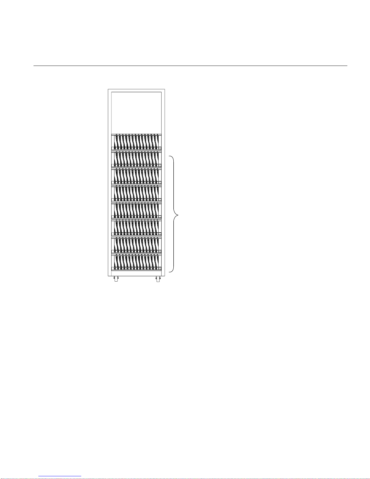
Controller enclosure
Expansion enclosures
System Components
Figure 1-3 TP9300 Rack with Enclosures Installed
007-4644-001 9

1: Introduction to the SGI TP9300
Figure 1-4 shows some of the features of the rack.
Standard
EIA rails
Cable access holes
Casters
Removable
stabilizer foot
Figure 1-4 Rack Features
For detailed specifications of the rack, see “Rack Specifications” on page 79.
10 007-4644-001

Chapter 2
2. Storage Enclosures
The storage enclosure is the basic building block of the TP9300. Each storage enclosure
provides redundant power and cooling to its individual components. The storage
enclosures also house the I/O components of the storage system.
There are two types of storage enclosures: controller enclosures and expansion
enclosures. As their name implies, controller enclosures contain the RAID controllers for
the storage system. The expansion enclosures provide expansion disk drive space. The
two types of storage enclosures share many of the same components. The only difference
between controller enclosures and expansion enclosures is the presence or absence of the
RAID controllers.
This chapter describes the components in both the controller and expansion enclosures
in the following sections:
• “Overview” on page 12
• “Disk Drives” on page 16
• “RAID Controllers” on page 17
• “Environmental Status Modules (ESMs)” on page 19
• “Fans” on page 20
• “Power Supplies” on page 21
• “Tray ID Switch” on page 23
• “Link Rate Switch” on page 24
• “SFP Transceivers” on page 25
007-4644-001 11

2: Storage Enclosures
Overview
Important: Several references are made in this chapter to the storage management
software (TPSSM). For complete information on the operation and use of this software,
see SGI TP9400 and SGI TP9500 Software Concepts Guide (007-4305-00x).
Figure 2-1 shows a front view of the storage enclosure. The front of the enclosure
contains the following components:
• Front bezel: The bezel is a removable decorative cover with holes for viewing the
status LEDs and openings for the drive bays.
• Disk drives: Up to 14 sled-mounted drives can be installed in the bays on the front
of the enclosure.
• LEDs: There are two LEDs for each of the 14 drive bays that indicate the status of
the drive: the drive active LED and the drive fault LED. There are also two LEDs
that indicate the status of the entire enclosure: the enclosure fault LED and the
enclosure power LED.
• Alarm mute button: This button silences the audible alarm of the controller
enclosure. The expansion enclosure does not have an alarm; therefore, the
expansion enclosure does not use this button.
Note: Controller enclosures and expansion controllers look identical when viewed from
the front.
12 007-4644-001
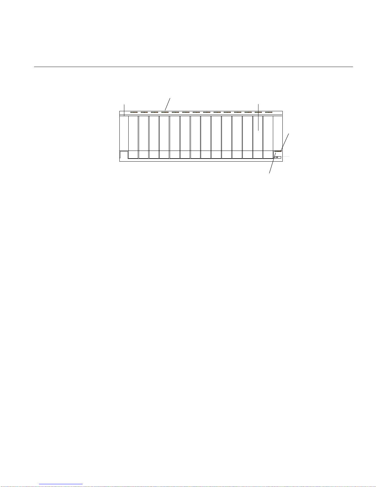
Drive status LEDs
Front bezel
Disk drive (14 total)
Enclosure power LED
Figure 2-1 Storage Enclosure Components (Front View)
Overview
Enclosure
fault LED
Alarm mute
007-4644-001 13

2: Storage Enclosures
Figure 2-2 shows a rear view of both a controller enclosure and an expansion enclosure.
The rear of the enclosures contain the following components:
• RAID controllers: Controller enclosures contain two 2882 RAID controllers.
• Environmental status modules (ESMs): Expansion enclosures have two ESM
modules in place of the RAID controllers.
• Fans: Two fans provide redundant cooling for the enclosure.
• Link rate/ enclosure ID switches: These switches indicate the connection speed and
set the ID number of the enclosure.
• Power supplies: Two power supplies provide redundant power for the enclosure.
14 007-4644-001

Controller enclosure
Overview
2882 RAID controllers
FanFan
Power supply
Link rate/ enclosure ID switches
Enviornmental Status Modules
Fan
Expansion enclosure
Power supply
Link rate/ enclosure ID switches
Figure 2-2 Storage Enclosure Components (Rear View)
Power supply
Fan
Power supply
007-4644-001 15

2: Storage Enclosures
Disk Drives
Each storage enclosure can contain up to 14 low-profile Fibre Channel disk drives.
Controller enclosures can be cabled to as many as seven expansion enclosures for a total
capacity of 112 disks in one storage system. Each disk is mounted in a sled for ease of
installation and removal. These drive sleds have a lever and latch mechanism that allows
you to cam the drive in and out of the enclosure. Figure 2-3 shows the drive sled and
drive bay numbering scheme for the TP9300.
Each drive has two status LEDs (see Figure 2-3) as follows:
• Drive active LED: This LED illuminates green when a drive is in the drive bay, and
it blinks when the drive is active.
• Drive fault LED: This LED illuminates amber when there is a problem with the
drive.
Locking lever
Drive active LED
Drive fault LED
Drives (14 total)
1 2 3 4 5 6 7 8 9 10 11 12 13 14
Drive sled latch
Figure 2-3 Disk Drives and Drive Bay Numbering
16 007-4644-001

RAID Controllers
RAID Controllers
Each TP9300 controller enclosure contains two 2882 RAID controller modules. These
controllers slide into the same opening that the ESMs occupy on the expansion
enclosures. Each controller contains RAID logic, cache memory, a rechargeable battery
for the cache, and additionalenvironmental monitoring circuitry. Each controller also has
two labels on its rear panel: one shows the MAC address of the controller and one shows
the battery service date (see Figure 2-4).
The RAID controllers provide the following features and capabilities:
• Support for RAID levels 0, 1, 3, and 5
• Dual-porting for failover
• Support for 2 hosts per controller (4 per controller module)
• 256 MB of cache memory with 7-day battery backup
• Array sizes up to 112 drives
• Data transfer rates up to 200 MB/s
The RAID controller has the following connectors (see Figure 2-4):
• 2 Fibre Channel host ports with small form-factor pluggable transceivers (SFPs)
• 1 Ethernet host port
• 1 Fibre Channel drive expansion port
• 1 RS-232 diagnostic port
The RAID controller has the following LED indicators (see Figure 2-4):
• Host 1 link and speed LEDs
• Host 2 link and speed LEDs
• Battery charging/charged LED
• Cache active LED
• Fault LED
• Expansion loop LED
• Expansion loop bypass LED
007-4644-001 17

2: Storage Enclosures
For more information about these LEDs, see “Checking the Indicator Lights” on page 34.
2882 controller
Latch
Lever
Pull ring
MAC address label
Battery label
Host 2
connector
Host 1
connector
Host 1 link
Host 1 speed
Host 2 speed
Host 1 link
Figure 2-4 2882 RAID Controller
Ethernet
connector
RS-232
Serial port
Fault
Cache
active
Battery
charging/charged
Expansion
loop connector
Expansion
loop bypass
Expansion
loop
18 007-4644-001

Environmental Status Modules (ESMs)
The expansion enclosures contain environmental status modules instead of 2882 RAID
controllers (see Figure 2-5). Each environmental status module contains an
environmental services monitor board and two slots for SFPs (small form-factor
pluggables). The environmental services monitor board is the interface between the
controller enclosure and the expansion enclosure, and it monitors expansion enclosure
status. If there are internal problems in the expansion enclosure, the environmental
services monitor board lights the appropriate fault LED. For more information about this
LED, see “Checking the Indicator Lights” on page 34.
ESM ESM
Environmental Status Modules (ESMs)
Figure 2-5 Environmental Status Modules
007-4644-001 19

2: Storage Enclosures
Fans
The storage enclosures each have two fan units. These fan units are mounted in the rear
of the enclosure (see Figure 2-6). They pull air through the front bezel to cool the internal
components of the enclosure. The air is exhausted out the rear of the fan units. The fans
provide redundant cooling of the enclosure. If one fan unit fails, the other fan unit runs
at a higher speed to compensate for the loss. Each fan unit has a fault light that
illuminates if there is a problem with the units.
Vent
Pull knob
Fault light
Figure 2-6 Fan Units
Fans
Latch
20 007-4644-001

Power Supplies
Power Supplies
Each storage enclosure contains two power supplies. These power supplies provide
power to the other components in the enclosure by converting incoming AC voltage to
DC voltage. The power supplies are redundant: if one supply fails, the other power
supply can keep the enclosure running until the failed unit can be replaced. Each power
supply has the following components on its rear panel (see Figure 2-7):
• Locking lever
• AC power input connector
• Power switch
• Power light
• Fault light
During normal operation, the power light is illuminated. If there is a problem with the
power supply, the fault light comes on.
For specification information about the power supplies, see “Wiring and Power” on
page 93.
007-4644-001 21

2: Storage Enclosures
Power supplies
Lever
AC power
connector
Power
switch
Power
light
Fault
light
Figure 2-7 Power Supplies
22 007-4644-001

Tray ID Switch
Tray ID Switch
The trayID switch is located between the power supplies on the rear of the enclosure (see
Figure 2-8). This switch assigns a unique identifier to every enclosure in the system. The
controller enclosure should always have its tray ID set to “00.” The first expansion
enclosure should be set to “01.” Each subsequent expansion enclosure should be
assigned the next highest ID. If more than one enclosure is set to the same ID number, the
conflict LED illuminates.
Note: Each enclosure in a storage system must have a unique ID. If you are installing
multiple systems in one rack, there maybe enclosures with the same ID numbersbecause
the systems are independent.
Enclosure ID switch
(Tray number)
0
0
Conflict LED
Figure 2-8 Tray ID Switch
007-4644-001 23
2: Storage Enclosures
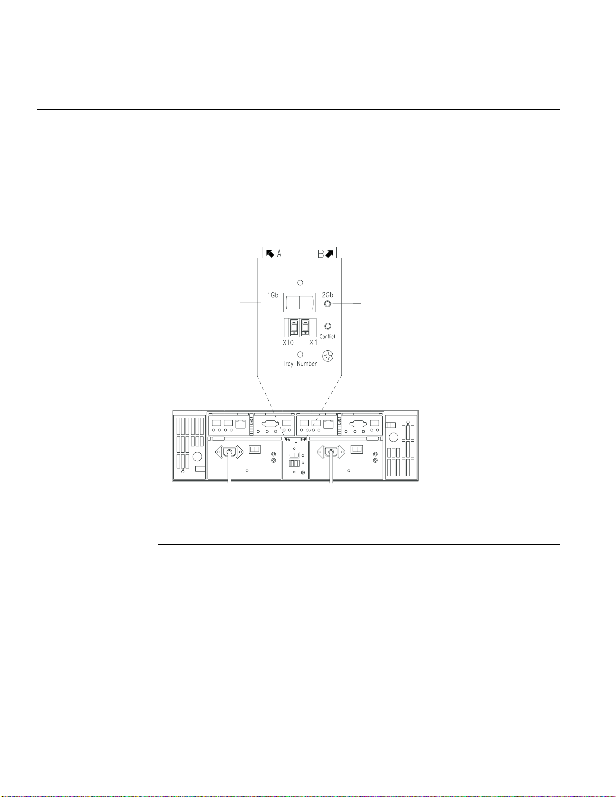
Link Rate Switch
The link rate switch is located on the same panel as the enclosure ID switch, between the
power supplies on the rear of the enclosure (see Figure 2-9). The link rate switch controls
the speed of the Fibre Channel connections to the enclosure. This switch should always
be set to 2 Gbit/s. When there is a 2 Gbit/s link present, the 2-Gbit link rate LED
illuminates green.
Link rate switch
0
0
2-Gbit link rate LED
Figure 2-9 Link Rate Switch
Note: The link rate switches on all enclosures in a system should be 2 Gbit/s.
24 007-4644-001
SFP Transceivers
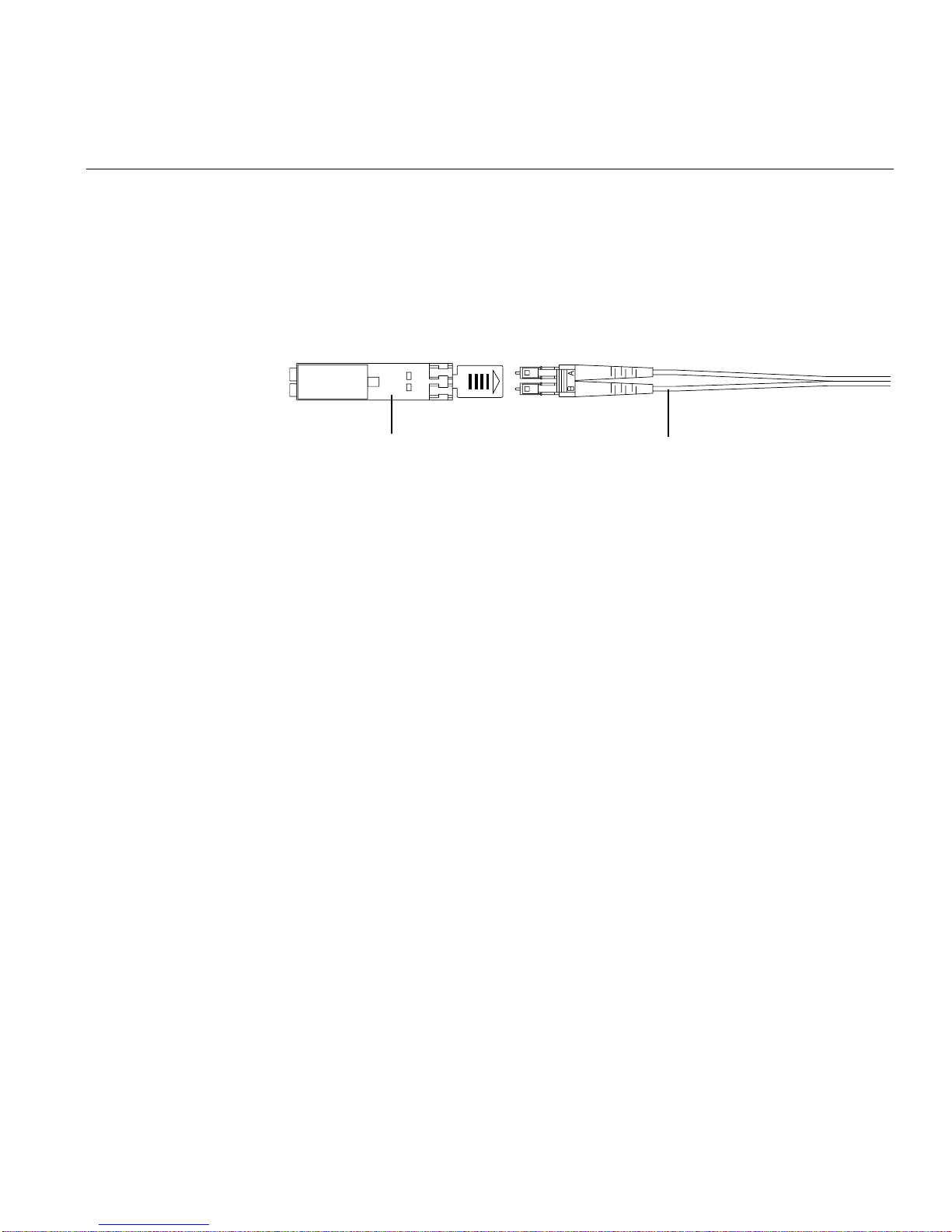
SFP Transceivers
An SFP (small form-factor pluggable) transceiver is a module that fits into the interface
connectors on the RAID controllers and the ESM modules (see Figure 2-10). Every Fibre
Channel cable that connects to a RAID controller or ESM module requires an SFP
transceiver.
SFP tranceiver Fiber-optic cable
Figure 2-10 SFP Transceiver
You can hot-swap a failed SFP transceiver, which means you can replace it while the
controller enclosure is in operation. If you replace the SFP transceiver and continue to
experience problems, the enclosure may have defective components or connections.
Check the storage management software (TPSSM) for indications of other component
failures.
007-4644-001 25


Chapter 3
3. Operating Storage Enclosures
This chapter describes the operation of the storage enclosures in the following sections:
• “Turning the Power On” on page 27
• “Turning the Power On after an Unexpected Shutdown” on page 29
• “Turning the Power Off” on page 32
• “Monitoring Status with Software” on page 33
• “Checking the Indicator Lights” on page 34
• “Moving the Enclosure” on page 40
Note: All of the procedures in this chapter apply to both the controller enclosures and
the expansion enclosures.
Turning the Power On
If the storage enclosure was turned off due to an unexpected shutdown or a power
failure, follow the instructions in “Turning the Power On after an Unexpected
Shutdown” on page 29.
Danger: Severe electrical shock can occur. Never turn on the power to any
equipment when there is evidence of fire, water, or structural damage. If there is
evidence of damage, call the factory or appropriate service organization for assistance.
Depending on the current service agreements, you may need to send the unit back to
the factory for repair/replacement.
007-4644-001 27

3: Operating Storage Enclosures
To turn on the enclosure after a normal shutdown (as described in “Turning the Power
Off” on page 32), turn on both power switches on the rear of the enclosure (see
Figure 3-1) or the main circuit breaker, whichever is applicable. You must turn on both
power supply switches to take advantage of the redundant power supplies.
Note: Always wait at least 30 seconds between the time you turn a power switch off and
the time you turn it back on again.
Note: To speed drive spin-up, it is recommended that you start the expansion enclosures
before or at the same time as the controller enclosure.
Power supply switches
Figure 3-1 Turning the Power On and Off
Note: The activity and fault indicators above the drive bays may flash intermittently as
the drives spin up. Wait until the enclosure has finished powering on before checking the
indicator lights on the front of the enclosure. All indicators should be green. If they are
not, use the storage management software (TPSSM) to diagnose the problem.
28 007-4644-001

Turning the Power On after an Unexpected Shutdown
Turning the Power On after an Unexpected Shutdown
The enclosure (and the entire storage array) may shut down unexpectedly under the
following conditions:
• If the internal temperature of the enclosure exceeds the maximum operating
temperature (an overtemp condition). See the “Troubleshooting an Overtemp
Condition” section for more information on overtemp conditions.
• If there is a general power failure or a loss of power to the storage array.
• If you are forced to shut down the storage array without performing the normal
shutdown procedures (in “Turning the Power Off” on page 32) due to an emergency
situation.
Note that in each of these cases, some data may be lost.
Warning: To avoid damage to the hardware, take special care when restarting the
enclosure after an unexpected shutdown.
If the enclosure shuts down unexpectedly, but there is still power to the site, use TPSSM
to determine if the enclosure has overheated.
• If an overtemp condition is indicated, follow the steps in “Turning the Power On
after an Overtemp Shutdown” on page 30 to restart the drive enclosure.
• If the enclosure has shut down due to a power failure or an emergency shutdown,
follow the steps in “Turning the Power On after an Emergency Shutdown” on
page 31 to restart the enclosure.
Troubleshooting an Overtemp Condition
If both fan units fail or are unable to maintain an internal temperature below 70ºC (158
º
F), one or both of the power supplies in the enclosure will shut down. If both power
supplies shut down, the enclosure is inoperable.
TPSSM warns you if the temperature of the enclosure is rising (before it has risen
sufficiently to shut down the power supplies). The first warning comes when the
enclosure temperature exceeds 40ºC (104ºF). The enclosure shuts down if the
temperature rises above 70ºC (158ºF).
007-4644-001 29

3: Operating Storage Enclosures
In the expansion enclosures, the overtemp indicator on the environmental status module
illuminates if the temperature reaches 40ºC (104ºF). If both power supplies shut down,
the overtemp indicator cannot come on. See Figure 3-3 on page 37 for the location of the
overtemp indicators on expansion enclosures.
The controller enclosure does not have an overtemp indicator. Check the storage
management software for temperature information about the controller enclosures.
Turning the Power On after an Overtemp Shutdown
To restart the enclosure after an unexpected shutdown due to an overtemp condition,
follow these steps:
1. Turn off both power switches (see Figure 3-1 on page 28).
2. Do whatever is necessary to cool the enclosure (replace the fans, use external fans to
cool the room, and so on).
Danger: Severe electrical shock can occur. Never turn on the power to any
equipment when there is evidence of fire, water, or structural damage. If there is
evidence of damage, call the factory or appropriate service organization for
assistance. Depending on the current service agreements, you may need to send
the unit back to the factory for repair/replacement.
3. Check all components and cables for visible damage. Do not power on the enclosure
if you find evidence of damage.
Note: To speed drive spin-up, it is recommended that you start the expansion
enclosures before or at the same time as the controller enclosure.
4. Once the internal temperature is below 40ºC (104ºF), turn on the power switches
and wait for the enclosure to power on.
5. Use TPSSM and the drive fault indicators (see “Checking the Indicator Lights” on
page 34) to check the overall status of the enclosure and its components. Repair any
faults found.
30 007-4644-001

Turning the Power On after an Emergency Shutdown
To restart the enclosure after a power failure or emergency shutdown, follow these steps:
1. After the emergency situation is over or power is restored to the site, turn off all
power switches (see Figure 3-1 on page 28).
Danger: Severe electrical shock can occur. Never turn on the power to any
equipment when there is evidence of fire, water, or structural damage. If there is
evidence of damage, call the factory or appropriate service organization for
assistance. Depending on the current service agreements, you may need to send
the unit back to the factory for repair/replacement.
2. Check all components and cables for visible damage. Do not power on the enclosure
if you find evidence of damage.
Note: To speed drive spin-up, it is recommended that you start the expansion
enclosures before or at the same time as the controller enclosure.
Turning the Power On after an Unexpected Shutdown
3. Turn on the power to the enclosures (see Figure 3-1 on page 28).
4. Use TPSSM and the drive fault indicators (see “Checking the Indicator Lights” on
page 34) to check the overall status of the enclosure and its components. Repair any
faults found.
007-4644-001 31

3: Operating Storage Enclosures
Turning the Power Off
The enclosure is designed to run continuously, 24 hours a day. However, you may need
to turn the power off for maintenance, such as upgrading the drives or replacing certain
modules.To turn the power off, follow these steps:
1. Use TPSSM to determine the status of your system components and any special
instructions before proceeding. The operating system software may require you to
perform other procedures before turning off the power.
2. Stop all I/O activity to the enclosure.
If applicable, use TPSSM to logically disconnect the enclosure from the host. Make
sure that all the drive activity indicators on the front of the enclosure are not
blinking (indicating I/O activity) and that the fast write cache indicator light on the
applicable RAID controller is off (not blinking).
3. Make sure that all the enclosure fault indicators are off (see Figure 3-2 on page 35
and Figure 3-3 on page 37).
If a fault indicator is on, correct the problem before turning off the power. Use
TPSSM to diagnose and fix the problem.
Warning: To shut off all power to an enclosure, you must turn off both power
switches and disconnect both power cords. An enclosure has two power switches
and two power cords. The enclosure continues to operate if both switches are not
turned off and both cords are not disconnected.
4. Turn off both power switches on the rear of the enclosure or the main circuit breaker,
whichever is applicable (see Figure 3-1 on page 28).
Important: Once the power is off, you must wait at least 30 seconds before you turn
it back on again.
5. After you have performed the necessary maintenance procedure, power on the
enclosure using the procedure in “Turning the Power On” on page 27.
32 007-4644-001

Monitoring Status with Software
Use storage management software (TPSSM) to monitor enclosure status. You should run
the software constantly and check it frequently.
TPSSM provides the best method to diagnose and repair failures. Thissoftware helps you
do the following:
• Determine the nature of the failure.
• Locate the failed component.
• Provide recovery procedures to repair the failure.
Although the enclosure has fault indicators, these lights do not necessarily indicate
which component has failed or needs to be replaced, orwhich type of recovery procedure
you must perform. In some cases (such as loss of redundancy in various components),
the fault light does not even come on. Only TPSSM can detect the failure.
For example, the recovery procedure for an impending drive failure (a predictive failure
analysis, or PFA, flag on a drive) varies depending on the drive status (hot spare,
unassigned, RAID level, current volume status, and so on). Depending on the
circumstances, a PFA flag on a drive can indicate a high risk of data loss (if the drive is in
a RAID0 volume) or a minimal risk (if the drive is unassigned). Only TPSSM can identify
the risk level and provide the necessary recovery procedures. Note also that in the case
of PFA flags, the global fault and drive fault indicators do not come on, so just checking
the indicators will not notify you of the failure, even if the risk of data loss is high.
Monitoring Status with Software
In addition, recovering from a failure may require you to perform procedures other than
replacing the component (such as backing up the volume or failing a drive before
removing it). TPSSM provides these procedures.
!
007-4644-001 33
Caution: If the software recovery procedures are not followed, data loss can result.
Note: For more information on the storage management software (TPSSM), see the SGI
TP9400 and SGI TP9500 RAID Administration Guide (007-4306-00x), the SGI TP9400 and
SGI TP9500 Software Concepts Guide (007-4305-00x), and the SGI Storage Area Network
Installation Instructions (108-0252-00x).

3: Operating Storage Enclosures
Checking the Indicator Lights
The enclosure’s indicator lights display the status of the enclosure and its components.
Green indicators mean a normal operating status; amber indicators mean a possible
failure.
It is important that you check all the indicators on the front and rear of the enclosure
when you turn on the power. Besides checking for faults, you can use the indicators on
the front of the enclosure to determine if the drives are responding to I/O transmissions
from the host.
Important: Except as described in the notes following Figure 3-2 and Figure 3-3, an
amber light indicates a component failure. If you see an amber indicator, run TPSSM to
diagnose and repair the problem.
To check the enclosure indicators and operating status, follow the guidelines in Table 3-1
on page 36 (front indicators) and Table 3-2 on page 38 (rear indicators). If any indicators
show anything other than a “normal” status, run TPSSM to diagnose and repair the
problem.
Front Indicator Lights
This section describes the front indicator lights for the controller and expansion
enclosures. Figure 3-2 shows the front indicators for the controller and expansion
enclosures.
34 007-4644-001

Checking the Indicator Lights
Drive active (green)
Front bezel
Rack front view
Drive fault (amber)
Drives (14 total)
Global power
Global fault
Figure 3-2 Storage Enclosure Front Indicator Lights
Note: The normal operating state of all indicators on the front panel is green. If an amber
indicator is on, or a green indicator is off, use TPSSM to determine the nature of the fault
and the recovery procedure.
Exception: If the drive fault indicators are blinking, it means that TPSSM is locating a
component. It does not indicate a failure.
007-4644-001 35

3: Operating Storage Enclosures
Table 3-1 describes the front indicator lights on the controller and expansion enclosures.
Table 3-1 Storage Enclosure Front Indicator Lights
Indicator Light Color Normal Operation
Drive activity indicator Green On, steady
On, blinking
b
Problem
Indicator Condition Indicated
Off No power to enclosure; no power to storage array;
drive not properly seated in drive enclosure; drive
a
not spun up.
Drive fault indicator Amber Off
On, blinking
On, steady Drive failure; drive failed by user.
c
Global power indicator Green On Off No power to drive enclosure; no power to storage
array; power supply failure; overtemp condition.
Global fault indicator
a. Always use the storage management software (TPSSM) to precisely identify a failure.
b. The drive activity indicator blinks if data is being processed on the drives; otherwise, the indicator is on, steady.
c. The drive fault indicator blinks when the storage management software (TPSSM) is locating a drive, volume, or storage array. Otherwise, it
is off.
d. Not all enclosure component failures will turn this light on. See “Monitoring Status with Software” on page 88 for more information.
d
Amber Off On Enclosure component failure.
Rear Indicator Lights
This section describes the rear indicator lights for the controller and expansion
enclosures. Figure 3-3 shows the rear indicators on the expansion enclosure and the
RAID controller. Controller enclosures have RAID controller LEDs, but not ESM LEDs.
36 007-4644-001

Checking the Indicator Lights
Enclosure and ESM LEDs
Fan fault
Host 1
connector
In bypass
Power
Host 2
connector
Power
Fault
Ethernet
connector
Overtemp
Out bypass
Power supply
fault
2-Gbit link rate
RS-232
Serial port
In bypass
Power
Fault
Conflict
Power
Expansion
loop connector
Overtemp
Out bypass
Power supply
fault
Fan fault
RAID controller module LEDs
Host 1 link
Host 1 speed
Figure 3-3 Storage Enclosure Rear Indicator Lights
007-4644-001 37
Host 2 speed
Host 2 link
Fault
Cache
active
Battery
charging/charged
Expansion
loop bypass
Expansion
loop

3: Operating Storage Enclosures
Table 3-2 describes the rear indicators on the expansion enclosure and RAID controller.
Note: The normal operating state of all indicators on the rear panel is green. If an amber
indicator is on, or a green indicator is off, use TPSSM to determine the nature of the fault
and the recovery procedure.
Table 3-2 Storage Enclosure Rear Indicator Lights
Component Indicator Light Color Normal Operation
RAID
controller
Host 1 link
Host 2 link
Green On Off No connection to host
module
Host 1 speed
Host 2 speed
Green On: 2 Gbit/s data
rate from host
Off: 1 Gbit/s data
rate from host
Battery
charging/charged
Green On: battery charged
Flashing: battery
charging
Cache active Green On Off Cache failure
Fault Amber Off On General failure
Expansion loop Green On Off
Expansion loop
Amber Off On
bypass
Environmental
status module
Environmental card
fault indicator
Amber Off On,
Problem
Indicator Condition Indicated
None
Off Battery failure
Failure of environmental card canister.
steady
a
Environmental card
Green On, steady Off No power to drive enclosure; no power to
power indicator
In, out bypass
Amber Off
indicators
Overtemp indicator
d
Amber Off On,
38 007-4644-001
On, steady
storage array; overtemp condition; power
supply failure.
b
steady
On,
SFP failure; cable failure; controller
c
enclosure minihub failure.
Overtemp condition; fan failure.
steady

Table 3-2 Storage Enclosure Rear Indicator Lights (continued)
Checking the Indicator Lights
Component Indicator Light Color Normal Operation
ID conflict indicator Amber Off On,
Problem
Indicator Condition Indicated
Enclosure number is set incorrectly;
steady
enclosure number is in use by another
a
subsystem on the loop.
Fan canister Fan fault indicator Amber Off On,
Fan canister failure; overtemp condition.
steady
Power supply
canister
Power supply fault
indicator
Power supply power
indicator
Amber Off On,
Power supply failure; overtemp condition.
steady
Green On, steady Off Power supply off; power supply
disconnected; power supply is seated
incorrectly; no power to drive enclosure; no
power to storage array.
a. Always use the storage management software (TPSSM) to precisely identify a failure.
b. If nothing is connected to the corresponding connector, this fault light is on. If a cable is connected and it is functioning properly, this light is
off.
c. This indicates a problem only if an SFP is plugged into the corresponding connector (see footnote a). Also, more than one bypass indicator
will be on if the connection fails. Usually, if an SFP fails, its bypass indicator will come on, as will the bypass indicator of the module to which
it is connected.
d. The overtemp indicator comes on if the internal drive enclosure temperature reaches 40ºC (104ºF). See “Troubleshooting an Overtemp
Condition” in this chapter for more information.
007-4644-001 39

3: Operating Storage Enclosures
Moving the Enclosure
Before moving the enclosure to a new location or before removing the enclosure from its
rack, it is highly recommended that you first remove all drive sleds from the enclosure.
Doing so helps safeguard the equipment and ensures a smoother transition to the new
location. Before removing the drive sleds, label each one so that you can reinstall them in
the correct order.
Instructions for depopulating the enclosure is provided in Chapter 4, “Replacing
Enclosure Components”.
Note: If you are removing an expansionenclosure so that you can connect itto a different
controller enclosure, you must delete all volumes and hot spares from the drives before
removing the unit. If you are moving the enclosure a significant distance (such as to
another building or city), it is recommended that you pack it in its original shipping
container.
Removing the Enclosure
To remove the enclosure from the rack, follow these steps:
1. Unsnap the side brackets from the front of the enclosure (see Figure 3-4).
2. Unscrew the front bezel from the mounting pins.
3. Using a flat-blade screwdriver, carefully remove the bezel from the front of the drive
enclosure. You must remove the bezel before you can remove the enclosure from the
rack.
40 007-4644-001
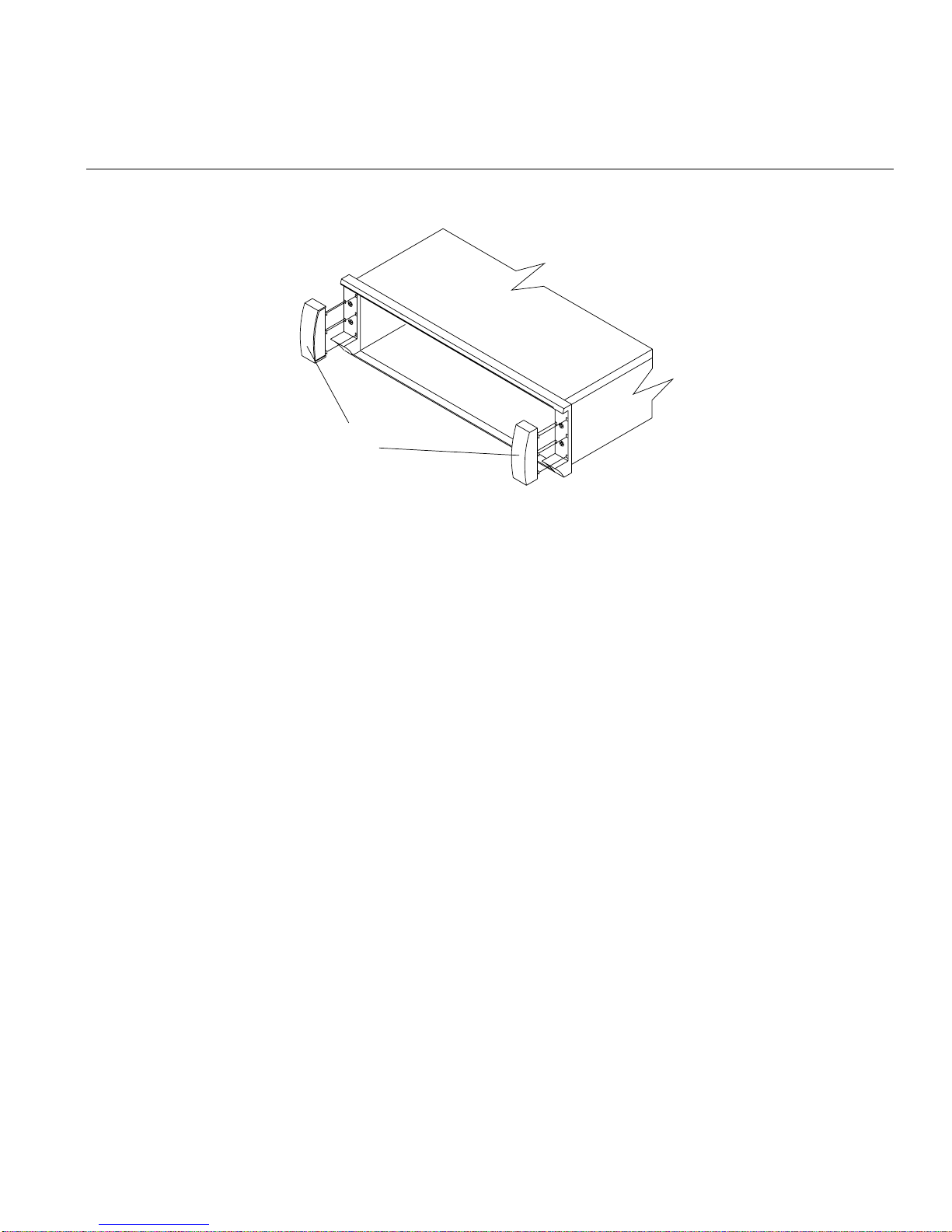
Moving the Enclosure
Side brackets
Figure 3-4 Removing the Side Brackets from the Enclosure
4. It is highly recommended that you remove all of the modules from the enclosure to
make it lighter and easier to remove. See Chapter 4, “Replacing Enclosure
Components” for information about depopulating an enclosure.
007-4644-001 41

3: Operating Storage Enclosures
5. Remove the front and rear mounting screws (see Figure 3-5). There are two
mounting screws at the rear, one for each support rail, and two mounting screws in
the front, one in each flange.
Rear mounting
screws
Drive enclosure
48279
Support rails
installed in rack
Remove
screw from
flange hole.
Do not remove
this screw from
the vertical rail.
Figure 3-5 Removing the Empty Drive Enclosure
6. Slide the enclosure out of the front of the rack.
7. Repeat steps 1 through 6 for any other enclosures to be moved.
42 007-4644-001

Reinstalling the Enclosure
To reinstall the enclosure into a rack, follow these steps:
1. Install the support rails in the rack. See the procedure in the SGI TP9300 RAID
Installation and Upgrade Guide (108-0401-00x).
2. From the front of the rack, slide the enclosure into the rack along the support rails
(see Figure 3-5).
3. Fasten the rear and front mounting screws (see Figure 3-5).
4. Slide the top of the front bezel over the indicator lights and snap into place (see
Figure 3-4).
5. Wearing antistatic protection, reinstall the components into the enclosure. See
Chapter 4, “Replacing Enclosure Components” for more information.
Moving the Enclosure
007-4644-001 43


Chapter 4
4. Replacing Enclosure Components
This chapter describes how to replace each component in the enclosure in the following
sections:
• “Replacing a Failed Disk Drive” on page 45
• “Replacing a Failed Fan” on page 48
• “Replacing a Failed Power Supply Module” on page 50
• “Replacing a Failed SFP Transceiver” on page 52
• “Replacing a Failed RAID Controller Module” on page 54
• “Replacing a Failed Environmental Status Module” on page 56
• “Upgrading Drives” on page 59
• “Adding Expansion Enclosures” on page 63
Replacing a Failed Disk Drive
When the storage management software (TPSSM) instructs you to replace a failed drive
module, read “Disk Drives” on page 16, and then follow the steps in this section.
Warning: Electrostatic discharge can damage sensitive components. Use a grounded
wrist strap or other antistatic precautions before handling enclosure components.
007-4644-001 45

4: Replacing Enclosure Components
1. Check TPSSM for instructions on drive failure recovery procedures. Follow any
instructions provided by the software before proceeding.
Caution: Removing the wrong drive can cause data loss. Ensure that you remove
!
only the failed drive. The drive fault indicator of the failed drive module illuminates
amber. Removing a drive module while its green activity indicator is blinking can
cause data loss and may cause the host controller to mark the drive as failed. If you
remove an active drive accidentally, wait at least 30 seconds and then reinstall it. See
TPSSM for further recovery instructions.
2. Locate the failed drive module (its fault light should be on).
3. Wearing antistatic protection, lift (open) the lever of the failed drive module.
4. Pull out the drive module (see Figure 4-1).
Drive lever
Drive
Figure 4-1 Removing and Installing a Drive Module
5. Wait at least 30 seconds for the drive to spin down. Then remove the failed drive
module from the enclosure.
6. Unpack the new drive module. Save all packing materials in case you need to return
the module.
46 007-4644-001

Replacing a Failed Disk Drive
7. Review all documentation shipped with the new drive module for updated
replacement procedures and other information. If necessary, modify the remaining
steps to meet the system requirements. Kits often contain the most current servicing
information. If the kit instructions conflict with those in this procedure, follow the
kit instructions.
Caution: If the temperature of the shipping or storage environment differs
!
!
significantly from the temperature of the environment in which the drive module
will be installed, acclimate the drive module before you install it.
8. Wearing antistatic protection, slide the new drive module fully into the slot.
Caution: Partial insertion of a drive may cause the controller to mark other drives
on the same bus as failed. Install a drive in one complete motion. Make sure that you
insert it all the way into the slot and lock it into place.
9. Lower (close) the lever. Wait for the new drive to spin up.
10. Check the drive activity and fault indicators above the new drive module. The
activity indicator should be on (either blinking or steady) and the fault indicator
should be off.
Note: The fault indicator may flash intermittently while the drive spins up. The
activity indicator blinks when data is being written to the new drive module.
• If the activity indicator is off, the drive module could be installed incorrectly.
Remove the drive module, wait 30 seconds, and then reinstall it.
• If the fault indicator stays on, or if the activity indicator stays off, the new drive
may be bad. Use TPSSM to determine the problem.
11. See the applicable software procedures (for TPSSM or other system software) for
instructions on bringing the drive module back online.
Important: Depending on your storage array configuration, the storage array may
automatically reconstruct data to the new drive module. If the array uses hot spares,
it may have to complete reconstruction on the hot spare before it copies the data to
the replaced drive. This increases the time required to complete this procedure. Use
TPSSM to determine the current status of the new drive and the progress of any
reconstruction or copyback.
007-4644-001 47

4: Replacing Enclosure Components
Replacing a Failed Fan
When TPSSM instructs you to replace a failed fan module, read “Fans” on page 20, and
then follow these steps:
Caution: Electrostatic discharge can damage sensitive components. Use a grounded
!
wrist strap or other antistatic precautions before handling enclosure components.
1. Check TPSSM for instructions on fan module failure recovery procedures. Follow
any instructions provided before proceeding.
2. Unpack the new fan module. Set the new fan module on a dry, level surface near the
enclosure. Save all packing materials in case you need to return the module.
3. Review all documentation shipped with the new fan module for updated
replacement procedures and other information. If necessary, modify the remaining
steps to meet the system requirements. Kits often contain the most current servicing
information. If the kit instructions conflict with those in this procedure, follow the
kit instructions.
4. If TPSSM instructs you to do so, turn off the power to the enclosure. Otherwise,
leave the power on.
Caution: To prevent the enclosure from overheating while in use, complete the fan
!
module replacement procedure within 15 minutes from the time you remove the
failed fanmodule to the time you install the new fan module. Both fan modules must
be installed in the enclosure to provide sufficient air circulation within the enclosure.
5. Locate the failed fan module (its fault light should be on).
6. Wearing antistatic protection, slide the latch to unlock the module (see Figure 4-2).
The latch is at the bottom of the left-side fan module, and at the top of the right-side
fan module.
7. Pull the knob to remove the fan module.
8. Determine the correct orientation for the new fan module. If replacing the module
on the left, orient the unit so the latch is at the bottom. If replacing the right-side
module, orient the unit so the latch is at the top.
9. Slide the new module into the slot.
48 007-4644-001

Fan
Latch
Figure 4-2 Removing and Installing a Fan Module
10. Push firmly until the latch snaps into place.
11. If you turned the power off, turn it back on.
Replacing a Failed Fan
12. Check the fault indicators as follows (see Figure 4-3):
• If the fan fault indicator is on or the fans are not spinning, the module might be
installed incorrectly. Remove the fan module and reinstall it.
• If any of the other fault indicators shown in Figure 4-3 are on, use TPSSM to
determine the problem.
Global fault
Front Rear
indicator
Fan canister fault indicator
Figure 4-3 Fault Lights for Fan Module Replacement
007-4644-001 49
Overtemp
indicators
Fan canister fault indicator
55008-f

4: Replacing Enclosure Components
Replacing a Failed Power Supply Module
When instructed by TPSSM to replace a failed power supply module, read “Power
Supplies” on page 21, and then follow these steps:
Warning: Electrostatic discharge can damage sensitive components. Use a grounded
wrist strap or other antistatic precautions before handling enclosure components.
1. Check TPSSM for instructions on power supply failure recovery procedures. Follow
any instructions provided before you proceed.
2. Unpack the new power supply module. Set the new power supply module on a dry,
level surface near the enclosure. Save all packing materials in case you need to
return the module.
3. Review all documentation shipped with the new power supply module for updated
replacement procedures and other information. If necessary, modify the remaining
steps to meet the system requirements. Kits often contain the most current servicing
information. If the kit instructions conflict with those in this procedure, follow the
kit instructions.
Danger: Shock can occur. Make sure the power supply is turned off and
unplugged before you remove or install it.
4. Locate the failed power supply (its fault light should be on).
5. Turn off the power and unplug the power cord from the failed module.
6. Remove the power cord from the power cord clip.
7. Wearing antistatic protection, grasp the pull-ring on the locking lever and squeeze
the tab against the ring to unlatch the lever (see Figure 4-4).
8. Pull open the lever and remove the failed module.
9. Check the lever to make sure the orientation is the same as the module it is
replacing. If not, move the lever to the pivot post on the other side.
50 007-4644-001

Replacing a Failed Power Supply Module
Locking lever
Power supply
Figure 4-4 Removing and Installing a Power Supply Module
Danger: Shock can occur. Make sure the power supply is turned off and
unplugged before you remove or install it.
10. Make sure that the power switch on the new power supply module is turned off.
11. Wearing antistatic protection, slide the new power supply module into the slot.
12. Close the lever and lock it into place.
13. Secure the power cord in the power cord clip.
14. Plug in the power cord and turn on the power switch.
15. Check that the power indicator on the new canister is on and that the fault indicator
is off (see Figure 4-4).
• If the power indicator is off, the canister might be installed incorrectly. Remove
it and reinstall it.
• If the fault indicator is on, or the power indicator stays off, use TPSSM to
determine the problem.
007-4644-001 51

4: Replacing Enclosure Components
Replacing a Failed SFP Transceiver
To replace a failed SFP transceiver, read “SFP Transceivers” on page 25, and then follow
these steps:
Caution: Electrostatic discharge can damage sensitive components. Use a grounded
!
wrist strap or other antistatic precautions before handling enclosure components.
1. Check TPSSM for instructions on SFP failure recovery procedures. Follow any
instructions provided before you proceed.
2. Unpack the new SFP transceiver. Set it on a dry, level surface near the enclosure.
Save all packing materials in case you need to return the SFP transceiver.
3. Review all documentation shipped with the new SFP transceiver for updated
replacement procedures and other information. If necessary, modify the remaining
steps to meet the system requirements. Kits often contain the most current servicing
information. If the kit instructions conflict with those in this procedure, follow the
kit instructions.
4. Locate the failed SFP transceiver.
Important: When an SFP transceiver fails, its bypass indicator glows amber, and so
does the bypass indicator of the module to which it is connected (including the fault
light on the controller enclosure). Make sure you remove the correct SFP transceiver.
Use the fault lights and TPSSM to locate the failed SFP transceiver.
5. Wearing antistatic protection, remove the Fibre Channel cables from the failed SFP
transceiver (see Figure 4-5).
Caution: Bending or damaging Fibre Channel cables can result in degraded
!
performance or data loss. Fibre Channel cables are fragile. Do not pinch the cables
with tie wraps, step on them, or bend at them sharp angles.
52 007-4644-001

Fiber-optic cable
SFP transceiver
Replacing a Failed SFP Transceiver
Interface
connector
Figure 4-5 Removing and Installing an SFP Transceiver
ESM
ESM
Note: Figure 4-5 shows SFPs being replaced in an expansion enclosure. The procedure is
the same for controller enclosures.
6. Remove the failed SFP transceiver from the environmental status module or RAID
controller.
7. Insert the new SFP transceiver into the environmental status module or RAID
controller.
8. Connect the Fibre Channel cables to the new SFP transceiver.
9. Check the bypass indicator next to the new SFP transceiver as follows (see
Figure 4-5):
• If the bypass indicator is on, the SFP transceiver might be installed incorrectly.
• If the bypass indicator stays on, or a fault indicator on the environmental status
007-4644-001 53
Remove the SFP transceiver and reinsert it.
module comes on, use TPSSM to determine the problem.

4: Replacing Enclosure Components
Replacing a Failed RAID Controller Module
When TPSSM instructs you to replace a failed RAID controller module, read “RAID
Controllers” on page 17, and then follow these steps:
Caution: Electrostatic discharge can damage sensitive components. Use a grounded
!
wrist strap or other antistatic precautions before handling enclosure components.
1. Check TPSSM for instructions on RAID controller module failure recovery
procedures. Follow any instructions provided before you proceed.
2. Unpack the new controller module. Set the new module on a dry, level surface near
the enclosure. Save all packing materials in case you need to return the controller.
3. Review all documentation shipped with the new RAID controller module for
updated replacement procedures and other information. If necessary, modify the
remaining steps to meet the system requirements. Kits often contain the most
current servicing information. If the kit instructions conflict with those in this
procedure, follow the kit instructions.
4. Locate the failed RAID controller module (its fault indicator should be on).
5. Disconnect the Fibre Channel cables from the SFP transceivers in the failed
controller module and then remove the SFP transceivers (see Figure 4-5). Label each
cable to ensure that all cables are properly reconnected to the new module.
Caution: Bending or damaging Fibre Channel cables can result in degraded
!
performance or data loss. Fibre Channel cables are fragile. Do not pinch the cables
with tie wraps, step on them, or bend at them at sharp angles.
6. Wearing antistatic protection, push down on the latch centered above the RAID
controller module. The levers will pop out of the locked position (see Figure 4-6).
7. Grasp the pull-rings and pull on the levers to remove the failed canister.
8. Wearing antistatic protection, slide the new RAID controller module all the way into
the empty slot.
9. Close both levers until the latch locks into place.
10. Install the SFP transceivers and Fibre Channel interface cables in their original
locations.
54 007-4644-001

Replacing a Failed RAID Controller Module
Controller
Lever
Figure 4-6 Removing and Installing a RAID Controller Module
11. Check the power and fault indicators on the new controller as follows (see
Figure 4-5):
• If the power indicator is off, the controller module may not have been inserted
correctly. Remove the module and reinsert it.
• If the fault indicator is on, the power indicator stays off, or any other fault
indicator is on, use TPSSM to determine the problem.
12. See TPSSM for instructions on bringing the RAID controller online.
007-4644-001 55
4: Replacing Enclosure Components
Replacing a Failed Environmental Status Module
When TPSSM instructs you to replace a failed environmental status module, read
“Environmental Status Modules (ESMs)” on page 19, and then follow the steps in this
section.
Caution: Electrostatic discharge can damage sensitive components. Use a grounded
!
wrist strap or other antistatic precautions before handling enclosure components.
1. Check TPSSM for instructions on environmental status module failure recovery
procedures. Follow any instructions provided before you proceed.
2. Unpack the new environmental status module. Set the new module on a dry, level
surface near the enclosure. Save all packing materials in case you need to return the
module.
3. Review all documentation shipped with the new environmental status module for
updated replacement procedures and other information. If necessary, modify the
remaining steps to meet the system requirements. Kits often contain the most
current servicing information. If the kit instructions conflict with those in this
procedure, follow the kit instructions.
4. Locate the failed environmental status module (its fault indicator should be on).
5. Disconnect the Fibre Channel cables from the SFP transceivers in the failed module,
and then remove the SFP transceivers (see Figure 4-7). Label each cable to ensure
that all cables are properly reconnected to the new module.
Caution: Bending or damaging Fibre Channel cables can result in degraded
!
56 007-4644-001
performance or data loss. Fibre Channel cables are fragile. Do not pinch the cables
with tie wraps, step on them, or bend at them at sharp angles.
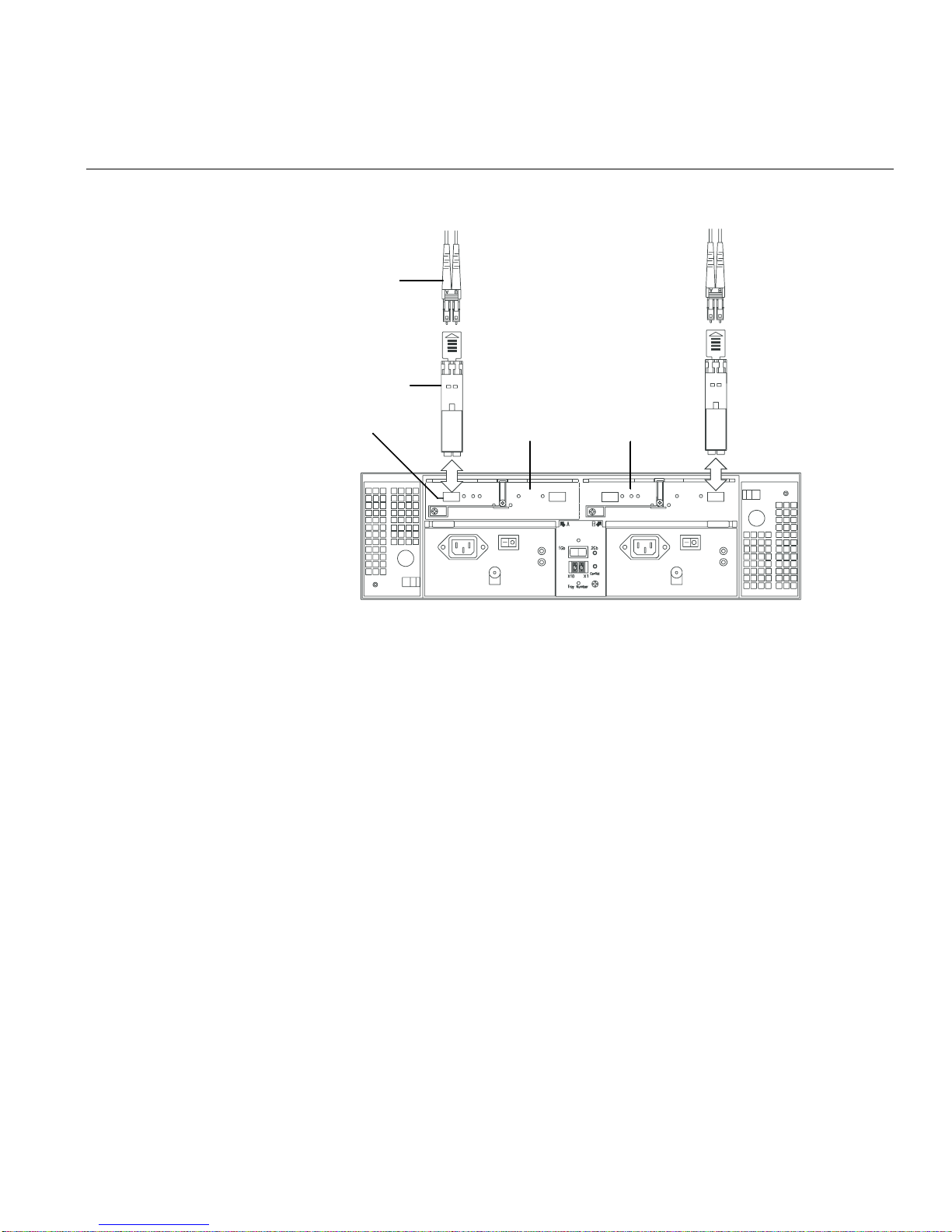
Fiber-optic cable
SFP transceiver
Replacing a Failed Environmental Status Module
Interface
connector
Figure 4-7 Removing SFPs from the Environmental Status Module
ESM
ESM
6. Wearing antistatic protection, push down on the latch centered above the
environmental status module. The levers will pop out of the locked position (see
Figure 4-8).
7. Grasp the pull-rings and pull on the levers to remove the failed module.
8. Wearing antistatic protection, slide the new environmental status module all the
way into the empty slot.
9. Close both levers until the latch locks into place.
10. Install the SFP transceivers and Fibre Channel interface cables in their original
locations.
11. Check the power and fault indicators on the new module (see Figure 4-7).
• If the power indicator is off, the module may not have been inserted correctly.
• If the fault indicator is on, the power indicator stays off, or any other fault
12. See TPSSM for instructions on bringing the environmental status module online.
007-4644-001 57
Remove the module and reinsert it.
indicator is on, use TPSSM to determine the problem.

4: Replacing Enclosure Components
Figure 4-8 Removing and Installing an Environmental Status Module
Latch
Lever
55020
58 007-4644-001

Upgrading Drives
You can upgrade drives in the following two ways:
• Add drives to empty slots in the enclosure (see “Adding a Drive to an Empty Slot”
on page 59).
• Replace existing drives with drives of larger capacity (see “Adding Drives of Larger
Capacity” on page 61).
Adding a Drive to an Empty Slot
Follow these instructions to install an additional drive into an empty slot in the
enclosure. You can install additional drives while the enclosure is powered on and
running.
Warning: Electrostatic discharge can damage sensitive components. Use a grounded
wrist strap or other antistatic precautions before handling enclosure components.
Upgrading Drives
1. Read the pertinent information in the software manuals supplied with your system
regarding drive upgrades and installation.
2. Check TPSSM and repair all reported problems.
3. Locate the blank drive module that you will replace with a drive, as follows:
• Because a blank drive module contains no drive, its activity indicator (on the
front bezel above the drive module) will not be on.
• Verify the drive position is blank using TPSSM.
Caution: Removing the wrong drive can cause data loss. Make sure you remove
!
007-4644-001 59
only a blank drive module. If you remove an active drive accidentally, wait at least
30 seconds and then reinstall it. Check TPSSM for further recovery instructions.
4. Wearing antistatic protection, lift (open) the lever of the blank drive module.
5. Pull out the blank drive module (see Figure 4-1 on page 46).
6. Unpack the new drive module. Save all packing materials in case you need to return
the module.

4: Replacing Enclosure Components
7. Review all documentation shipped with the new drive module for updated
replacement procedures and other information.
Caution: If the temperature of the shipping or storage environment differs
!
significantly from the temperature of the environment in which the drive module
will be installed, acclimate the drive module before you install it.
8. Slide the new drive module fully into the slot.
9. Lower (close) the lever.
10. Check to be sure that the drive activity indicators are on and that the fault indicators
above the new drive module are off.
Note: The fault indicator may flash intermittently while the drive spins up.
• If the activity indicator is off, the drive module may not be installed correctly.
• If the fault indicator stays on, or the activity indicator stays off, the new drive
Remove the drive module, wait 30 seconds, and then reinstall it.
may be bad. Use TPSSM to determine the problem.
11. Configure the new drive using TPSSM.
If you need to install more than one drive module, repeat the steps in this section.
60 007-4644-001

Adding Drives of Larger Capacity
This section provides guidelines for upgrading the disk drives in a storage array.
Carefully read your software documentation and this entire section to determine if you
should follow this procedure, a modified version of this procedure, or use a different
procedure provided by your operating system. Instructions provided with your software
should supersede the instructions in the section.
Warning: Electrostatic discharge can damage sensitive components. Use a grounded
wrist strap or other antistatic precautions before handling enclosure components.
The only method for upgrading disk drives is to replace them all at the same time. This
method requires you to back up the enclosure and shut down the storage array before
replacing the drives. After replacing all the drives, you must reconfigure the enclosure
and restore the data from backup media. This is the safest way to exchange drives
without losing data. However, this method may take a long time to complete because of
the backup, reconfiguration, and restoration processes. In addition, other users will not
be able to use the enclosure until you finish the procedure. You must use this method on
RAID 0 logical units (LUNs).
Upgrading Drives
Follow these instructions to replace all drives at the same time. All the data currently on
the drives will be lost when you replace the drives. You must use this method if you are
upgrading drives containing RAID 0 volumes.
1. Read the following:
• “Upgrading Drives” on page 59.
• Information in your software documentation.
• Documentation shipped with the new drives.
Read all precautionary notes, kit instructions, and other information. Kit
instructions often contain the most current information regarding the drives and
their installation, plus upgrade or servicing procedures. Compare the kit
instructions with this procedure to determine if you need to modify this procedure.
2. Check TPSSM and repair all reported problems.
3. Perform a complete backup of the drives that you are replacing. You need the
backup to restore data on the drives later in this procedure.
007-4644-001 61

4: Replacing Enclosure Components
4. Shut down all I/O activity on the enclosure. Make sure the drive activity indicators
on the front are not blinking.
5. Turn off both power switches on the rear of the enclosure.
6. Wearing antistatic protection, lift (open) the lever of a drive module and pull out the
drive module (see Figure 4-1 on page 46).
7. Repeat step 6 for all of the drive modules in the enclosure.
8. Unpack a new drive. Save the packing material and documentation in case you
need to return the drive.
9. Slide the new drive module fully into a slot.
10. Lower (close) the lever.
11. Repeat steps 8 through 10 until you have installed all the new drives.
12. Turn on both power switches on the enclosure.
13. Check to be sure that the drive activity indicators are on and that the fault indicators
above the new drive modules are off.
Note: The fault indicator may flash intermittently while the drive spins up.
• If the activity indicator is off, the drive module may not be installed correctly.
Remove the drive module, wait 30 seconds, and then reinstall it.
• If the fault indicator stays on, or the activity indicator stays off, the new drive
may be bad. Use TPSSM to determine the problem.
14. Use TPSSM to configure the new drives. See your software documentation for
detailed instructions.
15. Restore the data from backup to all the drives.
62 007-4644-001

Adding Expansion Enclosures
You can add new expansion enclosures to an existing storage array without turning off
the array or interrupting data flow.
Caution: You can add only new expansion enclosures to the storage array. This means
!
that there must be no existing information on the drives in the expansion enclosure you
want to install. If the enclosure you want to install currently contains volumes or
configured hot spare drives, you must delete them before adding the enclosure to a new
configuration.
You need torefer to the installation manual accompanying your controller and expansion
enclosures to complete this procedure.
To install one or more new expansion enclosures into an existing loop, follow these steps:
1. Follow the instructions in the SGI TP9300 RAID Installation and Upgrade Guide to set
up and mount the new expansion enclosures and to connect them to each other.
Adding Expansion Enclosures
2. Using Figure 4-9 as a guide, connect the cables from the controller enclosure to the
new expansion enclosure(s). Then, if applicable, connect the cables from the existing
expansion enclosure(s) to the new expansion enclosure(s).
Warning: Electrostatic discharge can damage sensitive components. Use a
grounded wrist strap or other antistatic precautions before handling enclosure
components.
3. After you have connected the cables to the new expansion enclosures, the
controllers will locate the new disk drives.
Important: Depending on how long it takes you to complete step 2, TPSSM may
report a loss of redundancy error on the expansion enclosures in the loop. This error
will not interfere with data flow, and will disappear after you finish installing the
expansion enclosure(s).
4. Use TPSSM to check the status of the new drives and correct any errors found.
5. Use TPSSM to configure the new drives.
007-4644-001 63
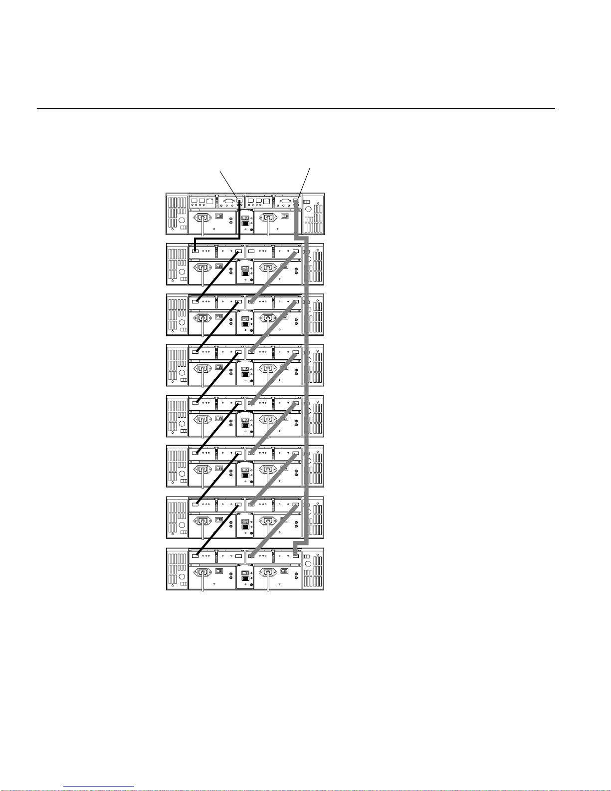
4: Replacing Enclosure Components
Controller A
Drive channel 1
Drive loop A
Controller B
Drive channel 2
Drive loop B
2Gb
1Gb
Conflict
X10
X1
Tray Number
2Gb
1Gb
Conflict
X10
X1
Tray Number
2Gb
1Gb
Conflict
X10
X1
Tray Number
2Gb
1Gb
Conflict
X10
X1
Tray Number
2Gb
1Gb
Conflict
X10
X1
Tray Number
Controller
enclosure ID 00
Expansion
enclosure ID 01
Expansion
enclosure ID 02
Expansion
enclosure ID 03
Expansion
enclosure ID 04
2Gb
1Gb
Conflict
X10
X1
Tray Number
2Gb
1Gb
Conflict
X10
X1
Tray Number
2Gb
1Gb
Conflict
X10
X1
Tray Number
Expansion
enclosure ID 05
Expansion
enclosure ID 06
Expansion
enclosure ID 07
Figure 4-9 Adding New Expansion Enclosures to an Existing Array
64 007-4644-001

Chapter 5
5. Cabling
This chapter describes the cabling between the controller enclosure, the front-end host,
and the expansion enclosures. It also covers Ethernet, serial port, and power connections
in the following sections:
• “Connecting the Drive Loop Cables” on page 65
• “Connecting the System to the Hosts” on page 69
• “Powering On the System” on page 75
Connecting the Drive Loop Cables
The system is designed to support redundant drive loops. A redundant drive loop
consists of one or more expansion enclosures connected to the controller enclosure using
two sets of data cables. If one data path fails, the controller uses the other data path to
maintain access to the drive group.
Follow these instructions to cable a group of enclosures into a redundant drive loop. If
the drive loop contains only one enclosure, skip this procedure and proceed to
“Connecting the System to the Hosts” on page 69.
Warning: Electrostatic discharge can damage sensitive components. Use
appropriate antistatic precautions before handling any components.
To complete this procedure, you will need two optic interface cables.
007-4644-001 65

5: Cabling
1Gb
X10
Tray Number
X1
Conflict
2Gb
1Gb
X10
Tray Number
X1
Conflict
2Gb
1. Connect the drive loops in the first two enclosures (see Figure 5-1). Starting with the
controller enclosure, connect an interface cable from the drive loop connector on the
left RAID controller module to the drive channel in connector on the left
environmental status module in the expansion enclosure.
2. Connect an interface cable from the drive loop connector on the right RAID
controller module to the drive channel out connector on the right environmental
status module in the expansion enclosure. This creates a redundant drive loop
between the two enclosures (see Figure 5-1).
ESM A
Drive channel in
Controller A
Drive channel 1
Drive loop A
2Gb
1Gb
00
Conflict
X10
X1
Tray Number
Controller B
Drive channel 2
Controller
enclosure ID 00
Drive loop B
ESM B
Drive loop out
Disk drive
2Gb
1Gb
01
Conflict
X10
X1
Tray Number
enclosure ID 01
Figure 5-1 Drive Loop Cabling for Systems with Two Enclosures
3. Connect additional drive enclosures to drive loops A and B by connecting the drive
channel out
connectors on the new enclosure to the drive channel in connectors of
the expansion enclosure directly beneath it (see Figure 5-2). Then connect the drive
loop out
cable from the left side RAID controller to the left-side drive channel in
connector on the new expansion enclosure. The drive channel out connector on the
first expansion enclosure should remain connected to the right-side RAID controller
drive loop connector.
66 007-4644-001

Connecting the Drive Loop Cables
1Gb
X10
Tray Number
X1
Conflict
2Gb
1Gb
X10
Tray Number
X1
Conflict
2Gb
1Gb
X10
Tray Number
X1
Conflict
2Gb
ESM A
Drive channel in
ESM A
Drive channel in
Controller A
Drive channel 1
Drive loop A
Drive loop A
Controller B
Drive channel 2
2Gb
1Gb
00
Conflict
X10
X1
Tray Number
Storage system
enclosure ID 00
Drive loop B
ESM A
Dive loop out
2Gb
1Gb
01
Conflict
X10
X1
Tray Number
ESM B
Drive loop out
Expansion
enclosure ID 01
Drive loop B
ESM B
Drive loop out
2Gb
1Gb
0
2
Conflict
X10
X1
Tray Number
Expansion
enclosure ID 02
ESM B
drive channel in
Figure 5-2 Drive Loop Cabling for Systems with Three or More Enclosures
4. Repeat step 3 to add up to seven expansion enclosures to the drive loop (see
Figure 5-3).
007-4644-001 67

5: Cabling
Controller A
Drive channel 1
Drive loop A
Controller B
Drive channel 2
Drive loop B
2Gb
1Gb
Conflict
X10
X1
Tray Number
2Gb
1Gb
Conflict
X10
X1
Tray Number
2Gb
1Gb
Conflict
X10
X1
Tray Number
2Gb
1Gb
Conflict
X10
X1
Tray Number
2Gb
1Gb
Conflict
X10
X1
Tray Number
Controller
enclosure ID 00
Expansion
enclosure ID 01
Expansion
enclosure ID 02
Expansion
enclosure ID 03
Expansion
enclosure ID 04
2Gb
1Gb
Conflict
X10
X1
Tray Number
2Gb
1Gb
Conflict
X10
X1
Tray Number
2Gb
1Gb
Conflict
X10
X1
Tray Number
Expansion
enclosure ID 05
Expansion
enclosure ID 06
Expansion
enclosure ID 07
Figure 5-3 Drive Loop Cabling for Systems with Eight Enclosures
68 007-4644-001

Connecting the System to the Hosts
You can connect your system to a host computer (or multiple host computers) in many
ways. The following figures show typical examples of connecting eitherby direct connect
or fabric connect. All examples assume dual-controller high -availability (HA)
configurations. The following topics are covered:
• “Examples of Direct Host Connection Cabling” on page 69
• “Examples of Fabric/Switch Host Connection Cabling” on page 72
• “Connecting Ethernet and Serial Cables for Array Management” on page 73
Warning: Electrostatic discharge can damage sensitive components. Use
appropriate antistatic precautions before handling any components.
Examples of Direct Host Connection Cabling
Connecting the System to the Hosts
The TP9300 can be connected directly to one or two hosts. These connections can be
configured with or without failover. Failover is a method of transferring I/O requests
from one controller to another when a component failure or other error occurs on the
data path to the first controller. Depending on the operating system of your host(s), you
may be able to choose from several failover options.
Note: If the host’s operating system does not support failover, the host can only be
connected to one controller. See Figure 5-5.
The following sections contain more information:
• “Direct Connection with Failover” on page 70
• “Direct Connection without Failover” on page 71
007-4644-001 69

5: Cabling
Direct Connection with Failover
Figure 5-4 shows the possible configurations for direct connection systems with failover.
Direct connection to single
host with dual HBAs
Host
Controller AController B Controller AController B
Controller
enclosure
Controller A
Host connectors
(SFP transceivers)
Direct connection to dual
hosts with dual HBAs
Host 1 Host 2
Controller
enclosure
Controller B
Host connectors
(SFP transceivers)
Figure 5-4 Direct Host Connection with Failover
70 007-4644-001

Direct Connection without Failover
Figure 5-5 shows the possible configurations for direct connection systems without
failover.
Connecting the System to the Hosts
Direct connection to dual
hosts with single HBAs
Host 1 Host 2
Controller B
Controller
enclosure
Controller A
Host connectors
(SFP transceivers)
Figure 5-5 Direct Host Connection without Failover
Controller B
Host connectors
(SFP transceivers)
Controller A
007-4644-001 71

5: Cabling
Examples of Fabric/Switch Host Connection Cabling
Figure 5-6 shows an example of connecting the TP9300 to hosts using a Fibre Channel
switch. For more information, see the “SGI Storage Area Network Installation
Instructions” (108-0252-00x) shipped with the Fibre Channel switch.
Figure 5-6 shows a simple switch configuration.
Host system
with two host
bus adapters
Host system
with two host
bus adapters
Switch Switch
Note: Other configurations
are possible
Controller
enclosure
Controller A
host connectors
(SFP transceivers)
Controller B
host connectors
(SFP transceivers)
Figure 5-6 Connecting to Hosts via a Fibre Channel Switch
72 007-4644-001

Connecting Ethernet and Serial Cables for Array Management
There are two methods of managing the storage system: in-band management and
out-of-band management. In-band management requires that only the Fibre Channel
host interface is present and functional. Out-of-band management requires that Ethernet
or serial connections are cabled to each controller.
Note: For more information on storage management, see the SGI TP9400 and SGI TP9500
RAID Administration Guide (007-4306-00x), the SGI TP9400 and SGI TP9500 Software
Concepts Guide (007-4305-00x), and the SGI Storage Area Network Installation Instructions
(108-0252-00x).
To connect Ethernet or serial (RS-232) interface cables to the controller enclosure for
direct management of the storage array, follow the steps in this section. Optionally, you
can use the Ethernet or serial connectors for diagnostic procedures.
Warning: Electrostatic discharge can damage sensitive components. Use
appropriate antistatic precautions before handling any components.
Connecting the System to the Hosts
007-4644-001 73

5: Cabling
1. To cable the system for direct management via Ethernet, connect a pair of Ethernet
interface cables from the storage management station to the Ethernet connectors for
controller A (left) and controller B (right) on the rear of the controller enclosure (see
Figure 5-7).
2. To cable the system for direct management via the RS-232 serial ports, connect a pair
of serial cables from the storage management station to the serial connectors for
controller A (left) and controller B (right) on the rear of the controller enclosure.
Storage Management
Station
Ethernet Connector
Ethernet
Network
Ethernet Connector
Controller B
Controller Enclosure
Ethernet Connector
Controller A
Figure 5-7 Connecting Ethernet Cables
74 007-4644-001
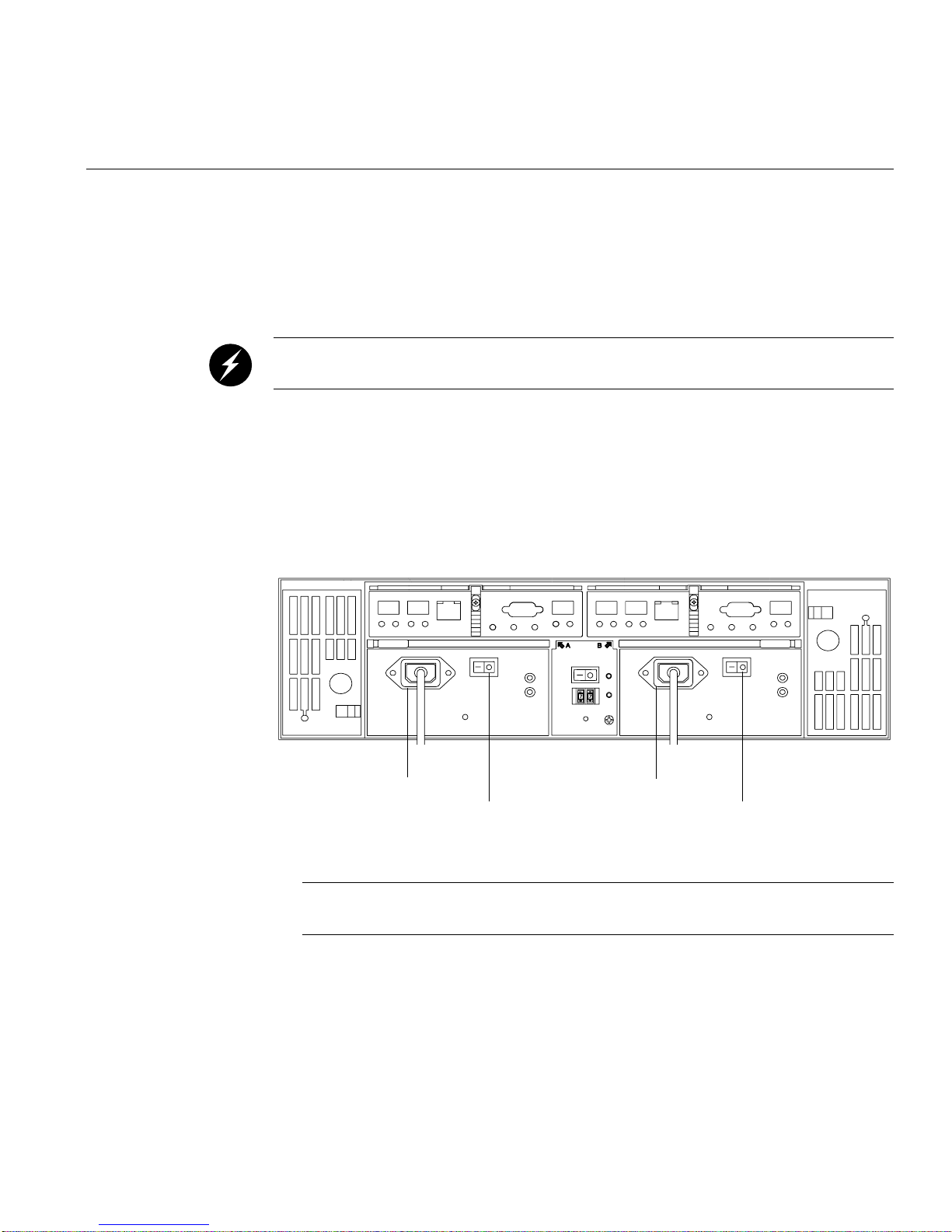
Powering On the System
1Gb
X10
Tray Number
X1
Conflict
2Gb
To connect the controller and the expansion enclosures to the AC power source and
power on the system, follow these steps:
Warning: Electrostatic discharge can damage sensitive components. Use
appropriate antistatic precautions before handling any components.
1. Make sure the switches on the power distribution units (on the rear of the rack
inside the access panel) are in the OFF position.
2. Make sure both power switches on each of the controller and expansion enclosures
are off.
3. Plug the power cords into each power supply of the storage enclosures (see “AC
power in” in Figure 5-8). Plug the left-side power cords into the left PDU and plug
the right-side power cords into the right PDU.
Powering On the System
2Gb
1Gb
Conflict
X10
X1
Tray Number
AC power in
Power switch
AC power in
Power switch
Figure 5-8 Power Connections and Switches of the Enclosures
Note: See Appendix A, “Specifications and Requirements” for details on power
requirements.
4. To keep the power cords from being accidently pulled from the power connections,
secure the cords in the strain relief power cord clips.
007-4644-001 75

5: Cabling
1Gb
X10
Tray Number
X1
Conflict
2Gb
5. To ensure power redundancy, plug each power distribution unit into a separate AC
power circuit (see Figure 5-9).
Controller enclosure
power supplies
2Gb
1Gb
Conflict
X10
X1
Tray Number
Expansion enclosure
power supplies
Power
distribution
units (PDUs)
Figure 5-9 PDU Cabling
Breaker
switches
76 007-4644-001

Powering On the System
Note: To speed drive spin-up, it is recommended that you start the expansion enclosures
before or at the same time as the controller enclosure. This procedure powers up all
components in the system at the same time by turning on the power distribution units.
6. Turn on both power switches on the rear of each expansion enclosure. Then turn on
both power switches on the rear of the controller enclosure (see Figure 5-8).
7. When all controller and drive enclosure power switches are in the ON position, flip
the breaker switches of both PDUs to the ON position (see Figure 5-9).
8. Check the indicator lights on the front and rear of each component. If any lights
indicate a fault, see “Checking the Indicator Lights” on page 34.
007-4644-001 77


Appendix A
A. Specifications and Requirements
This appendix describes the technical specifications and requirements of the TP9300
system rack and components in the following sections:
• “Rack Specifications” on page 79
• “Enclosure Specifications” on page 91
Rack Specifications
The system is housed in a 22-inch wide rack that contains two AC distribution boxes.
Standard EIA rails provide mounting holes for installing 19-inch wide devices. There are
roller casters and stability feet on the bottom of the rack for moving and leveling during
installation and relocation.
Figure A-1 shows a rack that contains eight enclosures: one controller enclosure and
seven expansion enclosures.
007-4644-001 79

A: Specifications and Requirements
Controller enclosure
Expansion enclosures
Figure A-1 Populated Rack
For more information on installation and cabling schemes, see the SGI TP9300 RAID
Installation and Upgrade Guide (108-0401-00x).
80 007-4644-001

Dimensions
Rack Specifications
Figure A-2 shows the system rack and its dimensions.
183 cm
(72 in.)
Figure A-2 Dimensions of the System Rack
007-4644-001 81
56 cm
(22 in.)
91 cm
(36 in.)

A: Specifications and Requirements
Weight
The total weight of the system depends on the quantity of enclosures installed. Table A-1
lists the overall weight of the rack, plus the maximum weight of an enclosure. You can
use these weights to estimate the total weight of your system, based on the number of
enclosures installed in the rack. Figure A-3 provides an example of calculating the
weight of a rack.
Table A-1 Rack, Crate, and Enclosure Weights
Rack
(Empty)
121 kg
(270 lb)
Crate
(Empty)
97 kg
(215 lb)
System Enclosure
(Maximum)
44.5 kg
(98.1 lb)
82 007-4644-001
 Loading...