


Silicon Graphics® Tezro™ Visual Workstation
Hardware User’s Guide: Tower Configuration
Document Number 007-4564-001

CONTRIBUTORS
Written by Matt Hoy
Production by Glen Traefald
Illustrated by Dan Young
Edited by Susan Wilkening
Engineering contributions by Charles Alexander, Steve Ewing, Brad Juskiewicz, Charlie Skandalis, Bruce Shifrin, Lyle Stoll, and MichaelWright.
COPYRIGHT
© 2003, Silicon Graphics, Inc. All rights reserved; provided portions may be copyright in third parties, as indicated elsewhere herein. No
permission is granted to copy, distribute, or create derivative works from the contents of this electronic documentation is any manner, in whole
or in part, without the prior written permission of Silicon Graphics, Inc.
LIMITED RIGHTS LEGEND
The electronic (software) version of this document was developed at private expense; if acquired under an agreement with the USA government
or any contractor thereto, it is acquired as "commercial computer software" subject to the provisions of its applicable license agreement, as
specified in (a) 48 CFR 12.212 of the FAR; or, if acquired for Department of Defense units, (b) 48 CFR 227-7202 of the DoD FAR Supplement;
or sections succeeding thereto. Contractor/manufacturer is Silicon Graphics, Inc., 1600 Amphitheatre Pkwy 2E, Mountain View, CA
94043-1351, USA.
TRADEMARKS AND ATTRIBUTIONS
Silicon Graphics, SGI, the SGI logo, IRIX, O2, Octane, Onyx, Onyx2, and Origin are registered trademarks, and O2+, Octane2, Stereo View,
Supportfolio, Tezro, and VPro are trademarks of Silicon Graphics, Inc., in the United States and/or other countries worldwide.
Macintosh is a registered trademark of Apple Computer, Inc. Magellan Spaceball is a trademark of the Logitech group. MIPS is a registered
trademark and R16000 is a trademark of MIPS Technologies, Inc., used under license by Silicon Graphics, Inc. in the United States and/or other
countries worldwide.
For regulatory and compliance information, see Appendix B, “Regulatory Information.”
Cover design by Sarah Bolles, Sarah Bolles Design, and Dany Galgani, SGI Technical Publications

Record of Revision
Version Description
001 July 2003
Original Publication
007-4564-001 iii


Contents
List of Figures . . . . . . . . . . . . . . . . . . . . . . . . xi
List of Tables . . . . . . . . . . . . . . . . . . . . . . . . xv
About This Guide. . . . . . . . . . . . . . . . . . . . . . xvii
Chapter Descriptions . . . . . . . . . . . . . . . . . . . . . xvii
Related Publications . . . . . . . . . . . . . . . . . . . . . xviii
Obtaining Publications . . . . . . . . . . . . . . . . . . . . xviii
Conventions . . . . . . . . . . . . . . . . . . . . . . . . xix
Product Support . . . . . . . . . . . . . . . . . . . . . . . xx
Reader Comments . . . . . . . . . . . . . . . . . . . . . . . xx
1. Installation and Operation Procedures . . . . . . . . . . . . . . . . 1
Setting Up the Workstation . . . . . . . . . . . . . . . . . . . . 1
Checking Your Shipment . . . . . . . . . . . . . . . . . . . 2
Lifting the Workstation . . . . . . . . . . . . . . . . . . . . 4
Getting Acquainted . . . . . . . . . . . . . . . . . . . . . 5
Cabling the Workstation . . . . . . . . . . . . . . . . . . . . 8
Using the Workstation . . . . . . . . . . . . . . . . . . . . . 11
Logging In to the Workstation . . . . . . . . . . . . . . . . . . 11
Using the IRIX Interactive Desktop . . . . . . . . . . . . . . . . . 13
Powering Off the Workstation . . . . . . . . . . . . . . . . . . 15
2. System Overview . . . . . . . . . . . . . . . . . . . . . . . 23
System Enclosure . . . . . . . . . . . . . . . . . . . . . . . 24
System Node Board . . . . . . . . . . . . . . . . . . . . . . 26
Processors . . . . . . . . . . . . . . . . . . . . . . . . . 27
Memory DIMMs . . . . . . . . . . . . . . . . . . . . . . . 27
Interface Board. . . . . . . . . . . . . . . . . . . . . . . . 29
IO9 Board . . . . . . . . . . . . . . . . . . . . . . . . . 31
007-4564-001 v

Contents
I/O Daughtercard . . . . . . . . . . . . . . . . . . . . . . . 32
Internal Hard Disk Drives . . . . . . . . . . . . . . . . . . . . . 33
DVD-ROM Drive . . . . . . . . . . . . . . . . . . . . . . . 35
Graphics Module . . . . . . . . . . . . . . . . . . . . . . . 35
PCI Buses . . . . . . . . . . . . . . . . . . . . . . . . . 38
Power Supply . . . . . . . . . . . . . . . . . . . . . . . . 40
Cooling System . . . . . . . . . . . . . . . . . . . . . . . . 40
Optional Components, Peripherals, and Upgrades. . . . . . . . . . . . . . 42
PCI Boards . . . . . . . . . . . . . . . . . . . . . . . . 42
Memory Upgrades. . . . . . . . . . . . . . . . . . . . . . 43
Processor Upgrades . . . . . . . . . . . . . . . . . . . . . 43
Graphics Options . . . . . . . . . . . . . . . . . . . . . . 43
Storage Upgrades . . . . . . . . . . . . . . . . . . . . . . 44
Displays. . . . . . . . . . . . . . . . . . . . . . . . . 44
Peripherals . . . . . . . . . . . . . . . . . . . . . . . . 44
3. Maintenance and Upgrade Procedures . . . . . . . . . . . . . . . . . 47
Safety Instructions . . . . . . . . . . . . . . . . . . . . . . . 48
Ordering Parts . . . . . . . . . . . . . . . . . . . . . . . . 49
Required Tools . . . . . . . . . . . . . . . . . . . . . . . . 49
Preparing the Workstation for Service . . . . . . . . . . . . . . . . . 49
Powering Off and Disconnecting the Workstation. . . . . . . . . . . . . 50
Removing the Enclosure Panels . . . . . . . . . . . . . . . . . . 51
Installing or Removing Internal Parts . . . . . . . . . . . . . . . . 56
Returning the Workstation to Service . . . . . . . . . . . . . . . . . 57
Installing the Bezel . . . . . . . . . . . . . . . . . . . . . 58
Installing the Side Panels . . . . . . . . . . . . . . . . . . . . 60
Cabling and Powering on the Workstation . . . . . . . . . . . . . . . 61
Installing or Removing a Memory DIMM . . . . . . . . . . . . . . . . 63
Removing a DIMM . . . . . . . . . . . . . . . . . . . . . 64
Installing a DIMM . . . . . . . . . . . . . . . . . . . . . . 65
Verifying Memory Installation . . . . . . . . . . . . . . . . . . 66
vi 007-4564-001

Contents
Installing or Removing Internal Hard Disk Drives . . . . . . . . . . . . . 67
Installing an Internal Hard Disk Drive . . . . . . . . . . . . . . . .67
Removing an Internal Hard Disk Drive . . . . . . . . . . . . . . . 69
Installing or Removing the DVD-ROM Drive . . . . . . . . . . . . . . . 71
Installing the DVD-ROM Drive . . . . . . . . . . . . . . . . . . 71
Removing the DVD-ROM Drive . . . . . . . . . . . . . . . . .74
Replacing the IO9 Board . . . . . . . . . . . . . . . . . . . . . 76
Removing the IO9 Board. . . . . . . . . . . . . . . . . . . . 76
Installing the IO9 Board . . . . . . . . . . . . . . . . . . . . 78
Installing or Removing XIO Boards . . . . . . . . . . . . . . . . . . 81
Installing the XIO Board Support Bracket . . . . . . . . . . . . . . . 81
Installing an XIO Board . . . . . . . . . . . . . . . . . . . . 83
Removing an XIO Board . . . . . . . . . . . . . . . . . . . . 85
Installing or Removing PCI Boards . . . . . . . . . . . . . . . . . . 88
Installing a PCI Board . . . . . . . . . . . . . . . . . . . . 89
Removing a PCI Board . . . . . . . . . . . . . . . . . . . . 92
Installing or Removing External devices . . . . . . . . . . . . . . . . 93
Replacing Cooling System Components . . . . . . . . . . . . . . . . 94
Replacing the Fan Wall . . . . . . . . . . . . . . . . . . . . 94
Replacing the Hard Disk Drive Fan. . . . . . . . . . . . . . . . . 95
Replacing the Rear Fan Assembly . . . . . . . . . . . . . . . . . 98
Replacing Internal Cables. . . . . . . . . . . . . . . . . . . . . 99
Replacing the L1 Display Cable . . . . . . . . . . . . . . . . . .100
Replacing the LED Cable. . . . . . . . . . . . . . . . . . . .103
Replacing the DVD-ROM Drive Cable . . . . . . . . . . . . . . . .105
Replacing Enclosure Components . . . . . . . . . . . . . . . . . .106
Replacing the Enclosure Plastics . . . . . . . . . . . . . . . . .106
Replacing the L1 Display. . . . . . . . . . . . . . . . . . . .108
4. Troubleshooting and Diagnostics . . . . . . . . . . . . . . . . . .113
Troubleshooting . . . . . . . . . . . . . . . . . . . . . . .114
Environmental Fault Monitoring . . . . . . . . . . . . . . . . .114
Bezel LEDs. . . . . . . . . . . . . . . . . . . . . . . .114
007-4564-001 vii

Contents
Diagnostics . . . . . . . . . . . . . . . . . . . . . . . . 115
Power-on Diagnostics . . . . . . . . . . . . . . . . . . . . 115
Offline Diagnostics . . . . . . . . . . . . . . . . . . . . 117
Online Diagnostics . . . . . . . . . . . . . . . . . . . . 120
A. Technical Specifications and Pinouts . . . . . . . . . . . . . . . . 125
Physical and Environmental Specifications . . . . . . . . . . . . . . . 126
Power Supply Specifications . . . . . . . . . . . . . . . . . . . 128
I/O Port Specifications. . . . . . . . . . . . . . . . . . . . . 128
Ethernet 10-Base-T/100-Base-T Port. . . . . . . . . . . . . . . . 128
Keyboard and Mouse Ports . . . . . . . . . . . . . . . . . . 130
Serial Ports . . . . . . . . . . . . . . . . . . . . . . . 131
Serial Cables and Adapter Specifications . . . . . . . . . . . . . . . 132
Printer/Dumb Terminal Serial Cable . . . . . . . . . . . . . . . 132
PC Modem Serial Cable . . . . . . . . . . . . . . . . . . . 133
Serial Port Adapter Cables . . . . . . . . . . . . . . . . . . 135
VPro Graphics Board I/O Port Specifications . . . . . . . . . . . . . . 137
DVI-I Video Port . . . . . . . . . . . . . . . . . . . . . 137
Stereo View Port . . . . . . . . . . . . . . . . . . . . . 140
Genlock Port . . . . . . . . . . . . . . . . . . . . . . 141
Swap Ready Port . . . . . . . . . . . . . . . . . . . . . 142
B. Regulatory Specifications . . . . . . . . . . . . . . . . . . . 143
CMN Number . . . . . . . . . . . . . . . . . . . . . . . 143
CE Notice and Manufacturer’s Declaration of Conformity . . . . . . . . . . 144
Electromagnetic Emissions . . . . . . . . . . . . . . . . . . . 144
FCC Notice (USA Only) . . . . . . . . . . . . . . . . . . . 144
Industry Canada Notice (Canada Only) . . . . . . . . . . . . . . 145
VCCI Notice (Japan Only) . . . . . . . . . . . . . . . . . . 146
Chinese Class A Regulatory Notice . . . . . . . . . . . . . . . . 146
Korean Class A Regulatory Notice . . . . . . . . . . . . . . . . 146
Shielded Cables. . . . . . . . . . . . . . . . . . . . . . . 146
Electrostatic Discharge. . . . . . . . . . . . . . . . . . . . . 147
Laser Compliance Statement . . . . . . . . . . . . . . . . . . . 147
viii 007-4564-001

Contents
Lithium Battery Compliance Statement. . . . . . . . . . . . . . . . .147
Index . . . . . . . . . . . . . . . . . . . . . . . . . .149
007-4564-001 ix


List of Figures
Figure 1-1 Workstation Shipment Contents . . . . . . . . . . . 3
Figure 1-2 Lifting the Workstation . . . . . . . . . . . . . 4
Figure 1-3 Front View of the Workstation . . . . . . . . . . . 6
Figure 1-4 Rear View of the Workstation. . . . . . . . . . . . 7
Figure 1-5 Connecting the Keyboard and Mouse Cables . . . . . . . 8
Figure 1-6 Connecting the Ethernet Cable . . . . . . . . . . . 9
Figure 1-7 Connecting the Monitor Cable . . . . . . . . . . . 10
Figure 1-8 Connecting the Workstation and Monitor Power Cables . . . . 11
Figure 1-9 Powering On the Workstation and Monitor. . . . . . . . 12
Figure 1-10 Login Screen . . . . . . . . . . . . . . . . 12
Figure 1-11 Peripheral Icons. . . . . . . . . . . . . . . . 13
Figure 1-12 Toolchest Menu. . . . . . . . . . . . . . . . 14
Figure 1-13 Console Window . . . . . . . . . . . . . . . 15
Figure 1-14 Powering Off the Workstation . . . . . . . . . . . 16
Figure 1-15 System Shutdown Notifier . . . . . . . . . . . . 16
Figure 1-16 Power Button and Reset Switch . . . . . . . . . . . 17
Figure 1-17 Shutdown Caution Message . . . . . . . . . . . . 18
Figure 1-18 Shutdown System Window . . . . . . . . . . . . 19
Figure 1-19 System Shutdown Notifier . . . . . . . . . . . . 19
Figure 1-20 Restart Notifier . . . . . . . . . . . . . . . . 20
Figure 1-21 System Shutdown Notifier . . . . . . . . . . . . 21
Figure 1-22 Power Off/Restart Notifier . . . . . . . . . . . . 21
Figure 1-23 Restart Notifier . . . . . . . . . . . . . . . . 21
Figure 2-1 System Enclosure Layout (Right-front view) . . . . . . . 24
Figure 2-2 System Enclosure Layout (Left-rear View) . . . . . . . . 25
Figure 2-3 IP53 System Node Board . . . . . . . . . . . . . 26
Figure 2-4 DIMM Sockets and Pairs . . . . . . . . . . . . . 28
007-4564-001 xi

List of Figures
Figure 2-5 Interface Board Connectors . . . . . . . . . . . . 30
Figure 2-6 IO9 Board . . . . . . . . . . . . . . . . . 31
Figure 2-7 I/O Daughtercard . . . . . . . . . . . . . . . 33
Figure 2-8 Hard Disk Drive Sled . . . . . . . . . . . . . . 34
Figure 2-9 Internal Hard Disk Drive Locations . . . . . . . . . . 34
Figure 2-10 Locating the Graphics Module. . . . . . . . . . . . 36
Figure 2-11 VPro Graphics and Dual Channel Display I/O Ports . . . . . 37
Figure 2-12 PCI Buses and Slots . . . . . . . . . . . . . . . 39
Figure 2-13 Power Supply Location. . . . . . . . . . . . . . 40
Figure 2-14 Cooling System Components . . . . . . . . . . . . 41
Figure 3-1 Powering Off the System . . . . . . . . . . . . . 50
Figure 3-2 Moving the Workstation . . . . . . . . . . . . . 51
Figure 3-3 Removing the Enclosure Side Panel . . . . . . . . . . 53
Figure 3-4 Removing the Bezel . . . . . . . . . . . . . . . 55
Figure 3-5 Installing the Bezel . . . . . . . . . . . . . . . 59
Figure 3-6 Replacing the Side Panel . . . . . . . . . . . . . 61
Figure 3-7 Reconnecting the Cables to the Workstation . . . . . . . . 62
Figure 3-8 Removing a DIMM . . . . . . . . . . . . . . . 64
Figure 3-9 Installing a DIMM . . . . . . . . . . . . . . . 65
Figure 3-10 Locating the Notches on a DIMM . . . . . . . . . . . 66
Figure 3-11 Installing an Internal Hard Disk Drive . . . . . . . . . 68
Figure 3-12 Removing an Internal Hard Disk Drive . . . . . . . . . 70
Figure 3-13 Installing the Drive Rails . . . . . . . . . . . . . 72
Figure 3-14 Installing the DVD-ROM Drive. . . . . . . . . . . . 73
Figure 3-15 Removing the DVD-ROM Drive . . . . . . . . . . . 75
Figure 3-16 Disconnecting the Cables and Retention Strap . . . . . . . 77
Figure 3-17 Opening the PCI Gate . . . . . . . . . . . . . . 77
Figure 3-18 Removing the IO9 Board . . . . . . . . . . . . . 78
Figure 3-19 Installing the IO9 Board . . . . . . . . . . . . . 79
Figure 3-20 Connecting the Cables and Retention Strap . . . . . . . . 80
Figure 3-21 Closing the PCI Gate . . . . . . . . . . . . . . 80
Figure 3-22 Installing the XIO Board Support Bracket . . . . . . . . 82
Figure 3-23 Opening the PCI Gate . . . . . . . . . . . . . . 83
xii 007-4564-001

List of Figures
Figure 3-24 Installing an XIO Board . . . . . . . . . . . . . 84
Figure 3-25 Closing the PCI Gate . . . . . . . . . . . . . . 85
Figure 3-26 Opening the PCI Gate . . . . . . . . . . . . . . 86
Figure 3-27 Removing an XIO Board . . . . . . . . . . . . . 87
Figure 3-28 Opening the PCI Gate . . . . . . . . . . . . . . 89
Figure 3-29 Installing the PCI Board . . . . . . . . . . . . . 90
Figure 3-30 Closing the PCI Gate . . . . . . . . . . . . . . 91
Figure 3-31 Opening the PCI Gate . . . . . . . . . . . . . . 92
Figure 3-32 Removing a PCI Board. . . . . . . . . . . . . . 93
Figure 3-33 Replacing the Fan Wall . . . . . . . . . . . . . 95
Figure 3-34 Removing the Hard Disk Drive Fan . . . . . . . . . . 96
Figure 3-35 Installing the Hard Disk Drive Fan . . . . . . . . . . 97
Figure 3-36 Replacing the Rear Fan Assembly . . . . . . . . . . 99
Figure 3-37 Removing the L1 Display Cable . . . . . . . . . . .101
Figure 3-38 Installing the L1 Display Cable . . . . . . . . . . .103
Figure 3-39 Replacing the LED Cable . . . . . . . . . . . . .104
Figure 3-40 Replacing the DVD-ROM Drive Cable . . . . . . . . .106
Figure 3-41 Replacing the Top Plastic . . . . . . . . . . . . .108
Figure 3-42 Removing the L1 Display Board . . . . . . . . . . .110
Figure 3-43 Installing the L1 Display Board . . . . . . . . . . .111
Figure A-1 Ethernet 10-Base-T/100-Base-T Port Pinout and Location. . . .129
Figure A-2 Keyboard and Mouse Port Pinouts and Locations . . . . . .130
Figure A-3 Serial Port Pinouts and Locations. . . . . . . . . . .131
Figure A-4 DVI-I Port Pinout and Location . . . . . . . . . . .137
Figure A-5 StereoView Port Pinout and Location . . . . . . . . .140
Figure A-6 Genlock Port Pinout and Location . . . . . . . . . .141
Figure A-7 Swap Ready Port Pinout and Location . . . . . . . . .142
Figure B-1 VCCI Notice (Japan Only) . . . . . . . . . . . . .146
Figure B-2 Chinese Class A Regulatory Notice . . . . . . . . . .146
Figure B-3 Korean Class A Regulatory Notice . . . . . . . . . .146
007-4564-001 xiii


List of Tables
Table 3-1 Component Access by Enclosure Panel . . . . . . . . . 52
Table 3-2 Customer-replaceable Components and Service Procedures . . . 56
Table 4-1 Bezel LED Signals . . . . . . . . . . . . . . .114
Table 4-2 Time Required to Run Offline Diagnostics . . . . . . . .118
Table 4-3 runalldiags Command-line Options . . . . . . . . .121
Table A-1 Physical Environment Specifications . . . . . . . . .126
Table A-2 Power Supply Specifications . . . . . . . . . . . .128
Table A-3 Ethernet 10-Base-T/100-Base-T Port Pinout . . . . . . . .129
Table A-4 Keyboard and Mouse Port Pinout . . . . . . . . . .130
Table A-5 Serial Port Pinout . . . . . . . . . . . . . . .132
Table A-6 Printer/Dumb Terminal Cable Pinout . . . . . . . . .133
Table A-7 PC Modem Cable Pinout . . . . . . . . . . . . .134
Table A-8 Female DB-9 to Female MiniDIN8 Adapter Cable Pinout . . . .135
Table A-9 Female DB-9 to Female DB-9 Adapter Cable Pinout . . . . .136
Table A-10 DVI-I Video Port Pinout . . . . . . . . . . . . .138
Table A-11 Supported VPro Graphics Board Scan Rates . . . . . . .139
Table A-12 Stereo View Pinout Assignments . . . . . . . . . . .140
Table A-13 Genlock Pinout Assignments . . . . . . . . . . . .141
Table A-14 Swap Ready Pinout Assignments . . . . . . . . . .142
007-4564-001 xv


About This Guide
Welcome to the user’s guide for the Silicon Graphics® Tezro™ visual workstation. Your
new workstation offers VPro graphics and a high-bandwidth architecture in a
convenient free-standing tower chassis. The workstation is available in a variety of
configurations and can be upgraded to meet your future needs.
Note: This User's Guide has been translated and is available to download from the SGI
Technical Publications Library at http://docs.sgi.com.
Enter the keywords Tezro visual workstation + <language> to find the version
you need.
This guide shows you how to set up, use, and troubleshoot your system. This guide is
provided for all end-users and SGI technical support staff. Most of the hardware tasks are
relatively simple and require no previous computer knowledge. A few tasks are more
difficult; they are easier to perform if you have some computer hardware experience.
Chapter Descriptions
The following topics are covered in this guide:
• Chapter 1, “Installation and Operation Procedures,” provides instructions for
unpacking and setting up your new workstation. It also explains how to power the
workstation on, log in, access programs, and power off the workstation.
• Chapter 2, “System Overview,” describes the parts of the system and gives an
overview of how they work together. It also provides configuration information and
describes optional components.
• Chapter 3, “Maintenance and Upgrade Procedures,” provides instructions for
installing and removing parts of the workstation. If the part you wish to add or
replace does not appear in this chapter, please contact your SGI service
representative.
007-4564-001 xvii

About This Guide
• Chapter 4, “Troubleshooting and Diagnostics,” explains how to find problems with
• Appendix A, “Technical Specifications and Pinouts,” provides specifications for the
• Appendix B, “Regulatory Specifications,” lists all regulatory information related to
Related Publications
For complete information on installing software, see the online Personal System
Administration Guide. It is located on your desktop in Toolchest > Help > Online Books.
For more advanced information, see the online IRIX Admin: Software Installation &
Licensing Guide. For system administration information, see the SGI_Admin section of
the online bookshelf.
your system and resolve them. It also includes instructions for running the system
diagnostics, which can help you find problems.
size, weight, and power consumption of the system. It also lists environmental
specifications and connector and cable pinouts.
use of the workstation in the United States and other countries and provides a list of
safety instructions to follow when installing, operating, or servicing the system.
It is always a good idea to back up your system. For instructions on backing up your
system, see the online Personal System Administration Guide.
Obtaining Publications
You can obtain SGI documentation, release notes, or man pages in the following ways:
• See the SGI Technical Publications Library at http://docs.sgi.com. Various formats
are available. This library contains the most recent and most comprehensive set of
online books, release notes, man pages, and other information.
• If it is installed on your SGI system, you can use InfoSearch, an online tool that
provides a more limited set of online books, release notes, and man pages. With an
IRIX system, select Help from the Toolchest, and then select InfoSearch. Or you can
type infosearch on a command line.
• You can also view release notes by typing either grelnotes or relnotes on a
command line.
• You can also view man pages by typing man <title> on a command line.
xviii 007-4564-001

About This Guide
SGI systems include a set of IRIX man pages, formatted in the standard UNIX “man
page” style. Important system configuration files and commands are documented on
man pages. These are found online on the internal system disk (or CD-ROM) and are
displayed using the man command. For example, to display the man page for the
Add_disk command, type the following on a command line:
man Add_disk
References in the documentation to these pages include the name of the command and
the section number in which the command is found. For example, “Add_disk(1)” refers
to the Add_disk command and indicates that it is found in section 1 of the IRIX
reference.
For additional information about displaying man pages using the man command, see
man(1).
In addition, the apropos command locates man pages basedon keywords. For example,
to display a list of man pages that describe disks, type the following on a command line:
apropos disk
Conventions
For information about setting up and using apropos, see apropos(1) and
makewhatis(1M).
The following conventions are used throughout this publication:
Convention Meaning
Command This fixed-space font denotes literal items such as commands, files,
routines, path names,signals, messages, and programming language
structures.
variable Italic typeface denotes variable entries and words or concepts being
defined. Italic typeface also is used for book titles.
user input This fixed-space font denotes literal items that the user enters in
interactive sessions. (Output is shown in nonbold, fixed-space font.)
[ ] Brackets enclose optional portions of a command or directive line.
... Ellipses indicate that a preceding element can be repeated.
007-4564-001 xix

About This Guide
Product Support
man page(x) Man page section identifiers appear in parentheses after man page
names.
GUI element This font denotes the names of graphical user interface (GUI)
elements such as windows, screens, dialog boxes, menus, toolbars,
icons, buttons, boxes, fields, and lists.
SGI provides a comprehensive product support and maintenance program for its
products, as follows:
• If you are in North America, contact the Technical Assistance Center at
+1 800 800 4SGI or contact your authorized service provider.
• If you are outside North America, contact the SGI subsidiary or authorized
distributor in your country.
Reader Comments
If you have comments about the technical accuracy, content, or organization of this
document, contact SGI. Be sure to include the title and document number of the manual
with your comments. (Online, the document number is located in the front matter of the
manual. In printed manuals, the document number is located at the bottom of each
page.)
You can contact SGI in any of the following ways:
• Send e-mail to the following address:
techpubs@sgi.com
• Use the Feedback option on the Technical Publications Library webpage:
http://docs.sgi.com
• Contact your customer service representative and ask that an incident be filed in the
SGI incident tracking system.
xx 007-4564-001

About This Guide
• Send mail to the following address:
Technical Publications
SGI
1600 Amphitheatre Parkway., M/S 535
Mountain View, CA 94043-1351
• Send a fax to the attention of “Technical Publications” at +1 650 932 0801.
SGI values your comments and will respond to them promptly.
007-4564-001 xxi


Chapter 1
1. Installation and Operation Procedures
This chapter shows you how to set up and use your Silicon Graphics® Tezro™ visual
workstation in the following sections:
• “Setting Up the Workstation” on page 1
• “Using the Workstation” on page 11
Setting Up the Workstation
This section covers the following topics:
• “Checking Your Shipment” on page 2
• “Lifting the Workstation” on page 4
• “Getting Acquainted” on page 5
• “Cabling the Workstation” on page 8
007-4564-001 1

1: Installation and Operation Procedures
Checking Your Shipment
Figure 1-1 shows the basic components that ship with your workstation. If parts of your
shipment are damaged or missing, contact your support provider.
2 007-4564-001

Workstation
Setting Up the Workstation
Mouse
Wrist strap
Power cables - 10 ft. each
CDs
Figure 1-1 Workstation Shipment Contents
Keyboard
Monitor
Monitor cable - 3 meters
007-4564-001 3

1: Installation and Operation Procedures
Lifting the Workstation
The base workstation configuration weighs 60 lb. (27 kg). SGI highly recommends that
two people lift the unit when it must be moved. Lift the unit by placing your hands under
the bottom edges of the chassis, as shown in Figure 1-2.
Figure 1-2 Lifting the Workstation
4 007-4564-001

Getting Acquainted
Setting Up the Workstation
To become familiar with your workstation, refer to the following figures:
• Figure 1-3, which shows the front view of the workstation.
• Figure 1-4, which shows the rear view of the workstation.
After you have set up your workstation and logged in, refer to the following resources
for more information:
• From the Toolchest, select System > System Manager for information on the
workstation’s hardware and software.
• From the Toolchest, select System > System Manager > About This System to
learn about your system’s serial number, IP address, operating system, and more.
007-4564-001 5

1: Installation and Operation Procedures
Status LEDs
Door release
Door
DVD ROM drive
L1 display
SCSI drives
Reset switch
Power on/off
button
Figure 1-3 Front View of the Workstation
6 007-4564-001
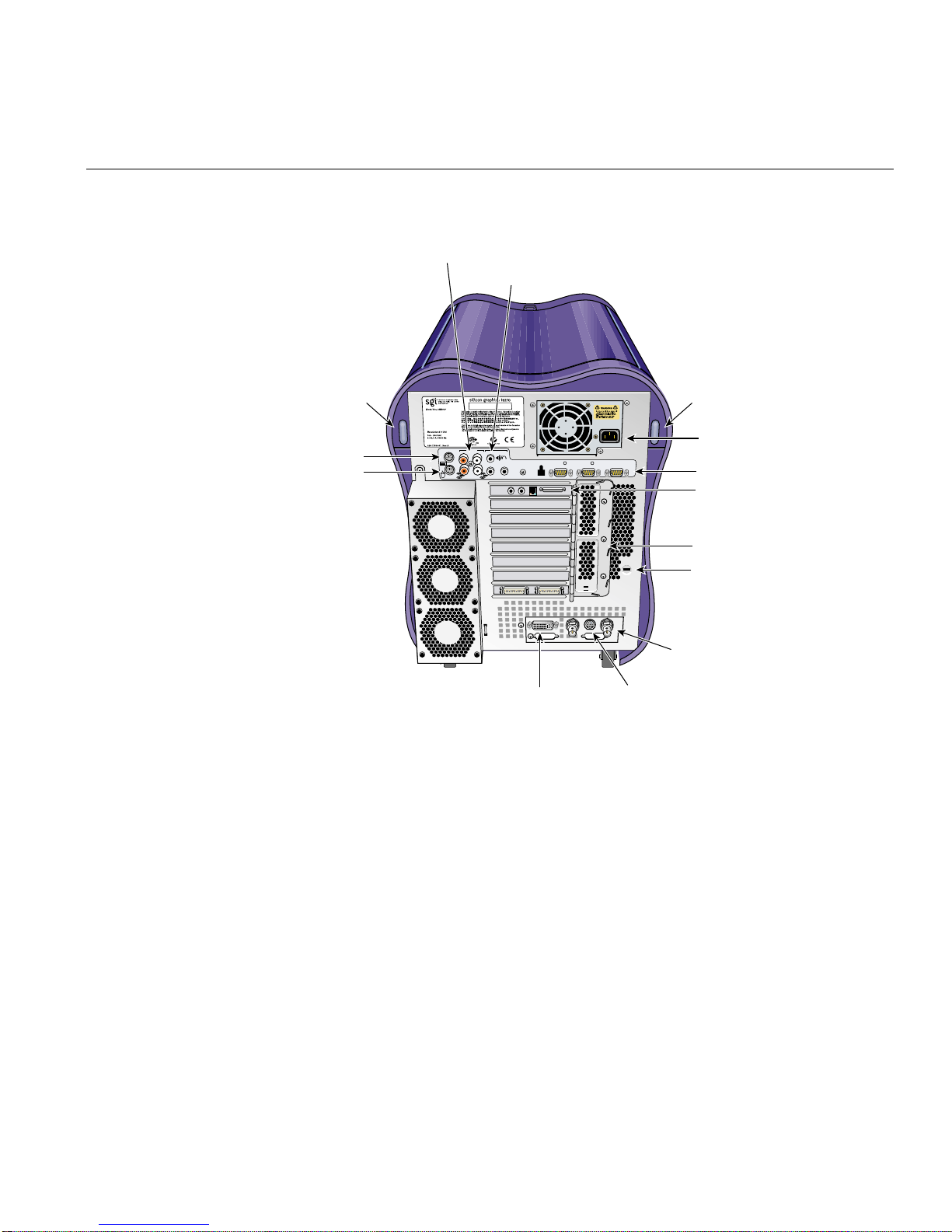
Line in and Line out (left)
Line in and Line out (right)
Audio jacks
Setting Up the Workstation
Side panel
release button
LINE
MIC
Keyboard
Mouse
L
+12VDC
L1 PORT IOIOI 1
1.0A
R
IN OUT
DVI-I video
Figure 1-4 Rear View of the Workstation
IOIOI 2
CONSOLE
Stereo View
Side panel
release button
AC power connector
CONSOLE port
IO9 PCI card
PCI gate
Kensington
lock slot
Genlock
007-4564-001 7

1: Installation and Operation Procedures
Cabling the Workstation
To set up the workstation, follow these steps:
1. Connect the keyboard and mouse cables, as shown in Figure 1-5.
Keyboard connector
Mouse connector
R
R
Figure 1-5 Connecting the Keyboard and Mouse Cables
8 007-4564-001

Setting Up the Workstation
2. Connect the Ethernet cable to the Ethernet port on the IO9 card, as shown in
Figure 1-6.
Ethernet connector
R
R
Figure 1-6 Connecting the Ethernet Cable
3. Connect the monitor cable, as follows (see Figure 1-7):
• Connect the monitor-to-graphics cable to the monitor.
• Connect the monitor-to-graphics cable to the DVI-I video connector on the back
of your workstation.
007-4564-001 9

1: Installation and Operation Procedures
Note: The workstation can be connected to a variety of monitors. Your monitor and
monitor cable may differ from those shown. If your monitor has multiple inputs,
ensure that the source switch is set to the correct input port.
R
R
Monitor cable
Figure 1-7 Connecting the Monitor Cable
4. Connect the power cables to your workstation and monitor. Then plug them into
approved electrical outlets (see Figure 1-8).
10 007-4564-001

R
R
A
C
IN
Figure 1-8 Connecting the Workstation and Monitor Power Cables
Using the Workstation
You have finished setting up your workstation. Proceed to the next section.
Using the Workstation
This section provides information about using your Silicon Graphics Tezro visual
workstation. The topics covered include:
• “Logging In to the Workstation” on page 11
• “Using the IRIX Interactive Desktop” on page 13
• “Powering Off the Workstation” on page 15
• “Restarting from the Toolchest” on page 19
Logging In to the Workstation
Press the power buttons on your monitor and workstation as shown in Figure 1-9.
007-4564-001 11

1: Installation and Operation Procedures
Figure 1-9 Powering On the Workstation and Monitor
A green LED flashing below the L1 display on the front of the workstation indicates that
the system is booting. The monitor may remain blank for a few moments.
If your system is booting for the first time, you will see a login screen similar to the
example shown in Figure 1-10.
:
e
m
a
n
n
i
g
o
L
Figure 1-10 Login Screen
12 007-4564-001

If you have a login account, double-click the icon with your login name. If you do not
have a login account, double-click EZsetup and then follow the instructions for creating
a personal login account and setting up the networking software. Then you can begin
using the IRIX interactive desktop to create a personal work area and communicate with
other users on your network.
Using the IRIX Interactive Desktop
After you have logged in, you are ready to use the IRIX Interactive Desktop. By default,
several icons appear on your desktop: a folder icon representing your home directory, a
dumpster icon, and icons forany peripherals you installed, examples of which are shown
in Figure 1-11.
The peripheral icons show the current state of the respective devices. For example, if you
insert a music CD into the DVD-ROM drive, the icon changes. When you double-click
the icon, it opens CD Player, a utility that allows you to play music from a compact disc.
Using the Workstation
Figure 1-11 Peripheral Icons
The Toolchest, located at the top left corner of your screen, provides access to system
functions, applications, hardware and software information, and documentation, as
shown in Figure 1-12.
Note: For a complete description of the Toolchest, select Help > InfoSearch from the
Toolchest, and type Desktop Users Guide.
007-4564-001 13

1: Installation and Operation Procedures
Figure 1-12 Toolchest Menu
System Manager
From the Toolchest, select System > System Manager to display the System Manager,
which shows your workstation’s hardware and software information.
Online Documentation
From the Toolchest, select Help to display the library of online documentation. If your
workstation is turned off and you cannot access online documentation, this printed
guide contains all the information you need. You can also access this guide and most
manuals, man pages, and release notes in the SGI Technical Publications Library at
http://docs.sgi.com, and through InfoSearch, as described in the next section.
InfoSearch
From the Toolchest, select Help > InfoSearch and type the name of the desired book or
topic to searchonline books, man pages, and release notes thatcover end-user, developer,
and system administrator information.
The Console Window
The small box next to the Toolchest is the Console window, as shown in Figure 1-13. It
appears as a small box because it is minimized. You can open it to its full size by clicking
it. Many system status and error messages appear in this window.
14 007-4564-001

Figure 1-13 Console Window
If you click in the Console window, an IRIX shell appears, where you can type IRIX
commands. For information on IRIX commands, select Help > Online Books. This will
launch the InfoSearch tool, which allows you to read documentation stored on your
workstation. Enter "Desktop User's Guide" in the Keyword search box. IRIX
commands are covered in Appendix A.
Powering Off the Workstation
Using the Workstation
You can shut down and power off your workstation in either of two ways, which are
explained in the following sections:
• “Powering Off with the Power Button” on page 15
• “Powering Off from the Toolchest” on page 17
Powering Off with the Power Button
To power off your workstation with the power button, follow these steps:
1. Open the door on the front of your workstation.
2. Press the power button, as shown in Figure 1-14.
007-4564-001 15

1: Installation and Operation Procedures
Figure 1-14 Powering Off the Workstation
Within a few seconds, a shutdown notifier appears, as shown in Figure 1-15. Within
a minute, the system powers off automatically.
Figure 1-15 System Shutdown Notifier
3. Turn off your monitor by pressing the monitor power button.
If your system does not power off and you do not see any activity for several
minutes, press the power button again.
Note: If you press the power button a second time, the system should power off
immediately, but this method does not perform a clean shutdown. Avoid using this
method unless the system does not respond for several minutes after you first press
the power button.
If pressing the power button a second time does not work, use a pen to press the
reset switch, shown in Figure 1-16. If the system still fails to power off, unplug the
power cable from the rear of your workstation and contact your service provider.
16 007-4564-001

Figure 1-16 Power Button and Reset Switch
Powering Off from the Toolchest
Using the Workstation
Reset switch
Power on/off
button
If you have root level access to the workstation, you can shut down your system from the
Toolchest. as follows:
1. From the Toolchest, select System > System Shutdown.
After a few seconds, a shutdown caution message appears, as shown in Figure 1-17.
007-4564-001 17

1: Installation and Operation Procedures
Figure 1-17 Shutdown Caution Message
2. Click the Power off the system check box.
The Shut Down System window appears. At this point, you can shut down and
power off the system or configure it to restart at a designated time, as shown in
Figure 1-18.
18 007-4564-001

Using the Workstation
Figure 1-18 Shutdown System Window
3. Click OK to shut down and power off the system.
The shutdown notifier appears, as shown in Figure 1-19. After a few seconds, the
system powers off.
Figure 1-19 System Shutdown Notifier
Restarting from the Toolchest
If you have root level access to the workstation, you can restart the system from the
Toolchest.
1. From the Toolchest, select System > Restart.
After a few seconds the restart notifier appears, as shown in Figure 1-20.
007-4564-001 19

1: Installation and Operation Procedures
Figure 1-20 Restart Notifier
20 007-4564-001

Using the Workstation
2. Click OK in the restart notifier.
The shutdown notifier appears, as shown in Figure 1-21.
Figure 1-21 System Shutdown Notifier
After a brief delay, the power off/restart notifier appears, as shown in Figure 1-22.
Figure 1-22 Power Off/Restart Notifier
3. Click Restart.
The restart notifier informs you that the system is coming up (restarting), as shown in
Figure 1-23.
Figure 1-23 Restart Notifier
007-4564-001 21


Chapter 2
2. System Overview
The Silicon Graphics® Tezro™ visual workstation is a high-power, high-performance
system. It features VPro™ graphics, 64-bit MIPS processors, and a high-bandwidth
architecture in a convenient free-standing tower chassis. This chapter provides general
information about the components of the workstation in the following sections:
• “System Enclosure” on page 24
• “System Node Board” on page 26
• “Processors” on page 27
• “Memory DIMMs” on page 27
• “Interface Board” on page 29
• “IO9 Board” on page 31
• “I/O Daughtercard” on page 32
• “Internal Hard Disk Drives” on page 33
• “DVD-ROM Drive” on page 35
• “Graphics Module” on page 35
• “PCI Buses” on page 38
• “Power Supply” on page 40
• “Cooling System” on page 40
• “Optional Components, Peripherals, and Upgrades” on page 42
007-4564-001 23

2: System Overview
System Enclosure
The Silicon Graphics Tezro visual workstation is installed in the system enclosure as
shown in Figure 2-1 and Figure 2-2. The enclosure provides structure and protection for
the internal components.
SCSI drive housing
IP53 processors
SCSI backplane
I/O daughtercard
SCSI drive fan
DIMMs
Airflow baffle
Figure 2-1 System Enclosure Layout (Right-front view)
24 007-4564-001

Power supply
R
R
R
R
R
R
Graphics module
System Enclosure
IO9 board
DVD drive housing
Interface
board
R
Fan wall
Digital media
XIO option board
Figure 2-2 System Enclosure Layout (Left-rear View)
007-4564-001 25

2: System Overview
System Node Board
The workstation is powered by an IP53 system node board (see Figure 2-3). The system
node board provides a mounting point and connectivity for the processor(s) and
memory DIMMs. The node board connects to the interface board via two connectors on
its underside.
Interface board
Figure 2-3 IP53 System Node Board
26 007-4564-001
DIMMs
Processors (under cover)
IP53 node board

Processors
Memory DIMMs
Processors
The workstation is available with 1, 2, or 4 R16000 MIPS processors. These processors are
available in several different clock speeds. Each processor has a total of 64 KB onboard
cache memory and 4-MB of external cache memory. The processors are mounted on the
system node board under a protective cover.
The workstation is configured with a minimum of 512 MB of memory and a maximum
of 8 GB of memory. Your system uses double data rate synchronous dynamic
random-access memory (DDR SDRAM). The DIMMs used in your workstation are
compatible with the DIMMs used in Origin 300, Origin 3000, and Onyx 3000 systems.
The DIMMs used in your workstation are not compatible with the DIMMs used in
Octane, Octane2, O2, O2+, Origin 200, Origin 2000, or Onyx2 systems.
The memory DIMMS are installed in eight DIMM slots on the system node board. The
DIMM slots are numbered 0 through 7 (see Figure 2-4). The slots are grouped into four
pairs of two DIMMs. The DIMM pairs are numbered as follows:
• DIMM pair 1: slots 0 and 1
• DIMM pair 2: slots 2 and 3
• DIMM pair 3: slots 4 and 5
• DIMM pair 4: slots 6 and 7
007-4564-001 27

2: System Overview
DIMM slot 7 DIMM Pair 4
DIMM slot 5 DIMM Pair 3
DIMM slot 3 DIMM Pair 2
DIMM slot 1 DIMM Pair 1
2.5-V VRM
1.5-V VRM
1.1-V to 1.8-V VRM
DIMM slot 6 DIMM Pair 4
DIMM slot 4 DIMM Pair 3
DIMM slot 2 DIMM Pair 2
DIMM slot 0 DIMM Pair 1
DIMM slot 7 DIMM Pair 4
DIMM slot 5 DIMM Pair 3
DIMM slot 3 DIMM Pair 2
DIMM slot 1 DIMM Pair 1
DIMM slot 6 DIMM Pair 4
DIMM slot 4 DIMM Pair 3
DIMM slot 2 DIMM Pair 2
DIMM slot 0 DIMM Pair 1
Figure 2-4 DIMM Sockets and Pairs
The following configuration rules apply to the memory banks and DIMMs in your
system:
• DIMM pair 1 must be present.
• DIMMs in the same DIMM pair must be the same density. For example, if DIMM 0
is 512 MB, then DIMM 1 must be 512 MB.
• DIMMs must be installed in pairs.
• The minimum amount of memory that should be installed in a 1-processor
workstation is 512 MB; the minimum for a 2- or 4-processor workstation is 1 GB.
For information on removing or installing memory DIMMs, see “Installing or Removing
a Memory DIMM” on page 63.
28 007-4564-001

Interface Board
Interface Board
The interface board connects the processors and memory mounted on the node board to
the graphics and I/O components of the system. It also provides card slots for the PCI
and graphics boards and distributes power to the system components. The interface
board has the following connectors (see Figure 2-5):
• XIO Slot connectors
There are two XIO slots: one for the VPro graphics board, and one for the
DMediaPro DM3-to-VBOB board
• PCI Slot connectors
There are eight PCI-X slots divided into three buses. For more information on the
PCI slots and buses, see “PCI Buses” on page 38.
The interface board also supplies connectivity and power to many of the system
components through the following connectors (see Figure 2-5):
• L1 display connector
• LED connector
• Power input connectors
• Fan wall connector
Note: Figure 2-5 depicts the interface board in a 2- or 4-processor workstation. The
interface board in a 1-processor workstation has 4 PCI-X slots (3 available) and 1 XIO slot.
007-4564-001 29

2: System Overview
PCI slots
Power input
connector
LED
connector
L1 display
connector
Fan wall
connector
XIO slot
for optional XIO
boards
XIO slot for
VPro graphics board
Figure 2-5 Interface Board Connectors
30 007-4564-001

IO9 Board
IO9 Board
The IO9 board is the full-length PCI board that is installed in PCI bus 1, slot 1. It provides
the following I/O connectors and interfaces for the workstation (see Figure 2-6):
• An internal IDE connector for the internal DVD-ROM drive
• An internal SCSI connector for the hard disk drives
• An external SCSI connector for optional external drives
• Real time interrupt in and out (RTI input and RTI output) connectors
• A 10/100BaseT Ethernet connector (RJ45)
The IO9 board also contains the non-volatile RAM and time-of-day clock for the system.
For technical specifications and pinouts of these connectors, see Appendix A, “Technical
Specifications and Pinouts”.
IO9 board
10/100BaseT
Ethernet
Figure 2-6 IO9 Board
007-4564-001 31
External SCSI
connector
RTI out
RTI in
Internal IDE connector
for DVD-ROM drive
Internal SCSI connector
for hard drives

2: System Overview
I/O Daughtercard
The I/O daughtercard is the long narrow board that is mounted on the rear of the
enclosure just below the power supply. This card acts as an extension of the IO9 board; it
provides the following connectors (see Figure 2-7):
• Two PS2 ports for keyboard and mouse
• Four RCA audio jacks (2 inputs, 2 outputs)
• Power port for external speakers (2.5 mm jack)
• Two 3.5 mm stereo audio jacks (one input, one output)
• Two serial ports (DB9)
• One L1 diagnostic port (USB-B)
• One console port (DB9)
32 007-4564-001

Internal Hard Disk Drives
Figure 2-7 I/O Daughtercard
For technical specifications and pinout of these connectors, refer to Appendix A,
“Technical Specifications and Pinouts”.
Internal Hard Disk Drives
LINE
L
R
IN OUT
MIC
+12VDC
1.0A
L1 PORT IOIOI 1
IOIOI 2
CONSOLE
The Silicon Graphics Tezro visual workstation supports one or two internal SCSI hard
disk drives. These drives provide the unit with large amounts of storage and quick access
times.
The hard disk drives in the workstation are sled mounted (see Figure 2-8). The drive
sleds provide a safe and easy way to install and remove the drives. The drive sleds also
007-4564-001 33

2: System Overview
provides a positive, locking connection to the SCSI backplane, which connects the disk
drives to the IO9 board (see Figure 2-9).
Figure 2-8 Hard Disk Drive Sled
DVD-ROM drive
Disk 2
Disk 1
IO9 board
IDE connector
SCSI connector
Figure 2-9 Internal Hard Disk Drive Locations
34 007-4564-001

DVD-ROM Drive
DVD-ROM Drive
The disks are numbered 1 and 2, with 1 being the bottom disk and 2 being the top. The
SCSI ID number of each disk must correspond with these drive numbers. Disk 1 is the
system disk, which has the IRIX operating system installed on it. Your workstation will
not function without the system disk.
For information on removing or installing an internal hard disk drive, refer to “Installing
or Removing Internal Hard Disk Drives” on page 67.
Your workstation supports an optional internal DVD-ROM drive.
The drive is installed in the 5.25-in. drive bay, as shown in Figure 2-9.
For information about installing and removing the DVD-ROM drive, refer to “Installing
or Removing the DVD-ROM Drive” on page 71.
Graphics Module
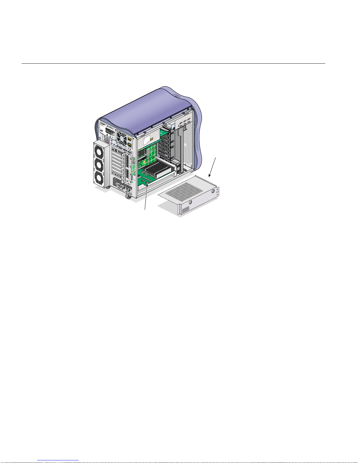
The graphics module is located near the bottom of your workstation, as shown in
Figure 2-10. It is made up of a metal cover, the VPro graphics boardand the optional Dual
Channel Display daughterboard. The metal shell protects the graphics board and
optional daughterboard and shields them from electrical interference.
The VPro graphics board has the following features:
• 128 MB of onboard SDRAM
• Analog RGB and TMDS video on a single DVI-I monitor port
• Additional ports for Swap Ready, Stereo View, and Genlock signals
The optional Dual Channel Display (DCD-2) daughterboard supplies two additional
DVI-I monitor ports. The daughterboard connects to the underside of the VPro graphics
board and allows you to display data across two monitors at once. For more information
about the optional Dual Channel Display daughterboard, contact your SGI sales
representative.
007-4564-001 35
2: System Overview
R
R
R
R
R
R
Graphics module
Figure 2-10 Locating the Graphics Module
Cover
Figure 2-11 shows the I/O ports of the VPro graphics board and optional Dual Channel
Display daughterboard.
36 007-4564-001

Graphics Module
Stereo View
L
R
L
Genlock
DVI-I video
Swap Ready
DCD right
DCD left
Figure 2-11 VPro Graphics and Dual Channel Display I/O Ports
For more information on the VPro graphics board and Dual Channel Display (DCD-2)
I/O ports, refer to “VPro Graphics Board I/O Port Specifications” in Appendix A.
007-4564-001 37

2: System Overview
PCI Buses
The 2- and 4-processor workstations have eight 64-bit, 3.3-V PCI-X slots which are
divided into four buses. The1-processor workstation has four 64-bit, 3.3-V PCI-X slots
which are divided into two buses. The IO9 board always occupies bus 1, slot 1, leaving
the remaining slots available for other boards. Each bus can support card speeds of up to
100 MHz. The slots are divided into buses, as shown in Figure 2-12.
Note: Figure 2-12 shows a 2- or 4-processor workstation. Buses 3 and 4 are not present
in 1 processor workstations.
• PCI Bus 1 has one slot, which always contains the IO9 board.
• PCI Bus 2 has three slots.
• PCI Buses 3 and 4 each have two slots.
• Bus 4, slot 2 shares a chassis opening with the second XIO slot. If you intend to
install a second XIO board, such as the DM3 Digital Media board, you cannot install
a PCI board in this slot.
Follow these rules when installing PCI and PCI-X boards on the PCI-X buses:
• Avoid placing high and low speed cards one the same bus. This forces the high
speed card to run at the same speed as the slower card. For example, placing a
100-MHz board on the same bus as a 33-MHz board forces the 100-MHz board to
run at the slower speed.
• Avoid placing storage and network boards on the same bus. These types of boards
use large amounts of bandwidth, and placing both types on the same bus can cause
the system to exceed the bandwidth of the bus.
• Spread the PCI boards across the buses as evenly as possible. For example, if you
have three PCI boards and three available PCI buses, install one board on each bus.
If you must install more than one board on a bus, group the boards by speed.
38 007-4564-001

PCI bus 1 slot 1
PCI bus 2 slot 1
PCI bus 2 slot 2
PCI bus 2 slot 3
PCI bus 3 slot 1
PCI bus 3 slot 2
PCI bus 4 slot 1
PCI bus 4 slot 2
PCI Buses
Figure 2-12 PCI Buses and Slots
For a list of available PCI boards see “PCI Boards” on page 42 or contact your SGI sales
representative.
007-4564-001 39

2: System Overview
Power Supply
The power supply for the workstation is located in the top rear quadrant of the chassis,
as shown in Figure 2-13.
Power supply
R
R
R
R
R
R
R
Figure 2-13 Power Supply Location
The power supply provides up to 550 watts of power to the node and interface boards,
internal hard disk drives, DVD-ROM drive, and other optional components installed in
the enclosure. For detailed information about the power supply specifications, refer to
Appendix A, “Technical Specifications and Pinouts”.
Cooling System
The workstation uses a total of eight fans to cool the internal components. The following
components make up the cooling system (see Figure 2-14):
• Fan Wall
The fan wall is a plastic housing that contains two 60-mm (2.4-in.) fans and two
80-mm (3.1-in.) fans. These fans provide cooling for the interface board, PCI boards,
and the graphics module.
40 007-4564-001

Cooling System
• Disk Drive Fan
The disk drive fan is an 80-mm fan that mounts directly behind the disk drives.
• Rear Fan Assembly
The rear fan assembly is made up of a sheet metal enclosure and three 80-mm fans.
These fans provide cooling for the system node board and memory DIMMs. The
rear fan assembly is mounted to the rear of the enclosure with hooks and a screw.
Note: The power supply is cooled by its own internal fan.
Disk drive fan
Power supply fan
Fan wall
Rear fan assembly
Figure 2-14 Cooling System Components
007-4564-001 41

2: System Overview
Optional Components, Peripherals, and Upgrades
Various optional components, peripherals, and upgrades are available for your
workstation. The following sections describe some of these options:
• “PCI Boards” on page 42
• “Memory Upgrades” on page 43
• “Processor Upgrades” on page 43
• “Graphics Options” on page 43
• “Storage Upgrades” on page 44
• “Displays” on page 44
• “Peripherals” on page 44
For more information about upgrading your system contact your SGI sales
representative.
PCI Boards
A wide variety of PCI options are available for you workstation, including networking,
audio, and video boards. The following boards a sample of the available options:
• Dual port Ultra3 SCSI LVD or single-ended SCSI adapter
• Single-port 1-gigabit Fibre Channel board with optical or copper connector
• Single- and dual-port 2-gigabit Fibre Channel boards with optical connectors
• 33- and 64-MHz, 64-bit single port ATM boards
• 1-port copper gigabit Ethernet adapter
• 1-port 1000Base-SX gigabit Ethernet adapter
• 8-channel Digital Audio I/O board
• DMedia DM3-to-VBOB board (2-or 4-processor workstations only)
For a complete list of available boards, contact your sales representative.
42 007-4564-001

Memory Upgrades
Processor Upgrades
Optional Components, Peripherals, and Upgrades
The following memory upgrades are available for the workstation:
• 512-MB DIMM pair (1-processor workstations only)
• 1-GB DIMM pair
• 2-GB DIMM pair
Note: The workstation supports a maximum of eight memory DIMMs totalling 8 GB.
Memory DIMMs must be installed in pairs of the same size.
The workstation is available with 1, 2, or 4 processors. The processors are available with
several different clock speeds. Processor upgrades are accomplished by replacing the
entire system node board. 2-processor workstations can be upgraded to 4-processor
workstations by replacing the node board.
Note: 1-processor workstations cannot be upgraded with 2- or 4-processor node boards.
Graphics Options
A varietyof graphics options are available for you workstation. The following boards are
a sample of the available options:
• Dual-Channel Display (DCD-2) daughterboard
This board attaches to the VPro graphics board and allows data to be displayed
across two monitors. It has two DVI-I video ports.
• DMediaPro DM5 HD & SD Graphics to Video Output Option
This board allows direct output from graphics to video. The board is available with
or without the video break-out box (VBOB) option.
• DMediaPro DM3 HD & SD Graphics Video I/O XIO
This board allows direct input and output between graphics and video. The video
break-out box (VBOB) is included with this board.
007-4564-001 43

2: System Overview
Storage Upgrades
For a complete list of available graphics options, contact your sales representative.
The following storage upgrades are available for the workstation:
• 18-GB internal Ultra SCSI hard disk drive, 15000 RPM
• 73-GB internal Ultra SCSI hard disk drive, 10000 RPM
• External SCSI DAT drive
• Internal DVD-ROM drive
The workstation can also be connected to a storage array, such as the SGI Total
Performance 9100, SGI Total Performance 9300, or SGI Total Performance 9400. These
disk arrays offer large storage capacities in both RAID and JBOD configurations.
In addition to the items listed above, there are a variety of other storage solutions
available from SGI. For more, information, contact your SGI sales representative.
Displays
The following displays are available with the workstation:
• 21-in. SGI CRT monitor
• 24-in. SGI CRT monitor (wide-aspect-ratio)
• Silicon Graphics F180 (18.1-in. flat panel monitor)
• Silicon Graphics F220 (22-in. wide-aspect-ratio flat panel monitor)
Peripherals
The following peripherals are available with the workstation:
• 3-button mouse
• beeping keyboard
• Speakers
• Magellan Spaceball programmable trackball
44 007-4564-001

Optional Components, Peripherals, and Upgrades
For a complete list of available components, contact your SGI sales representative or see
the following webpage:
http://www.sgi.com/peripherals/workstation/
007-4564-001 45


Chapter 3
3. Maintenance and Upgrade Procedures
This chapter provides safety information and instructions for adding or removing
components from your Silicon Graphics® Tezro™ visual workstation. These topics are
covered in the following sections:
• “Safety Instructions” on page 48
• “Ordering Parts” on page 49
• “Required Tools” on page 49
• “Preparing the Workstation for Service” on page 49
• “Returning the Workstation to Service” on page 57
• “Installing or Removing a Memory DIMM” on page 63
• “Installing or Removing Internal Hard Disk Drives” on page 67
• “Installing or Removing the DVD-ROM Drive” on page 71
• “Replacing the IO9 Board” on page 76
• “Installing or Removing XIO Boards” on page 81
• “Installing or Removing PCI Boards” on page 88
• “Installing or Removing External devices” on page 93
• “Replacing Cooling System Components” on page 94
• “Replacing Internal Cables” on page 99
• “Replacing Enclosure Components” on page 106
Caution: For your own safety and to avoid damage to your equipment, do not attempt
to install or remove components that are not listed in this chapter.
007-4564-001 47

3: Maintenance and Upgrade Procedures
Safety Instructions
Read and follow these instructions carefully before servicing your workstation.
1. Follow all warnings and instructions marked on the system and noted in this and
other documentation included with this system.
2. Unplug the system from the wall outlet before cleaning. Do not use liquid cleaners
or aerosol cleaners. Use a damp cloth for cleaning.
3. Do not use the workstation near water.
4. Do not place the system on an unstable cart, stand, or table. It may fall, causing
serious damage to the system.
5. Slots and openings on the workstation are provided for ventilation. To ensure
reliable operation of the system and to protect it from overheating, these openings
must not be blocked or covered. This system should never be placed near or over a
radiator or heat register, or in a built-in installation, unless proper ventilation is
provided.
6. This system should be operated from the type of power indicated on the marking
label. If you are not sure of the type of power available, consult your dealer or local
power company.
7. Do not allow anything to rest on the power cord. Do not locate this system where
people will walk on the cord.
8. Never push objects of any kind into this system through cabinet slots as they may
touch dangerous voltage points or short out parts, which could result in a fire or
electric shock. Never spill liquid of any kind on the system.
9. Do not attempt to service this system yourself except as noted in this guide.
Opening or removing covers of node and switch internal components may expose
you to dangerous voltage points or other risks. Refer all servicing to qualified
service personnel.
10. Unplug this system from the wall outlet and refer servicing to qualified service
personnel under the following conditions:
• When the power cord or plug is damaged or frayed.
• If liquid has been spilled into the system.
• If the system has been exposed to rain or water.
• If the system does not operate normally when the operating instructions are
followed. Adjust only those controls that are covered by the operating
48 007-4564-001

Ordering Parts
Ordering Parts
instructions since improper adjustment of other controls may result in damage
and will often require extensive work by a qualified technician to restore the
system to normal condition.
• If the system has been dropped or the cabinet has been damaged.
• If the system exhibits a distinct change in performance, indicating a need for
service.
11. Use only the proper type of power supply cord set (provided with the system) for
this unit.
12. Only qualified service personnel should replace the soldered lithium battery(s) in
the workstation. Please see “Lithium Battery Compliance Statement” on page 147
for more information.
Replacement parts are available directly from your local service provider. Contact the
SGI support office for more information.
Required Tools
All of the procedures in this chapter can be performed with the following tools:
• Wrist grounding strap
• T15 Torx driver
• Small flat-blade screwdriver
• Small phillips-blade screwdriver
Preparing the Workstation for Service
This section shows you how to open the workstation for service and protect the
components from static damage. The following topics are covered:
• “Powering Off and Disconnecting the Workstation” on page 50
• “Removing the Enclosure Panels” on page 51
007-4564-001 49

3: Maintenance and Upgrade Procedures
• “Installing or Removing Internal Parts” on page 56
Powering Off and Disconnecting the Workstation
Follow these steps to power off and remove cables from your workstation:
1. If you are logged in to the workstation, log out. Then, press the power buttons to
power off your workstation and monitor (see Figure 3-1).
Figure 3-1 Powering Off the System
2. Disconnect all of the cables from the rear of the workstation. Be sure to note where
each cable is connected, so that you can reconnect them correctly when you have
finished servicing the system.
Note: You do not need to disconnect the cables or move the workstation for some
procedures. Refer to the individual procedures for detailed instructions on preparing the
system.
3. Move the workstation to a sturdy, flat surface. Always use two people to move the
workstation (see Figure 3-2).
50 007-4564-001

Preparing the Workstation for Service
Figure 3-2 Moving the Workstation
Removing the Enclosure Panels
This section shows you how to open the enclosure in the following sections.
• “Determining Which Enclosure Panels to Remove” on page 52
• “Removing the Left or Right Side Panel” on page 52
• “Removing the Enclosure Bezel” on page 54
007-4564-001 51

3: Maintenance and Upgrade Procedures
Determining Which Enclosure Panels to Remove
To determine which side(s) of the enclosure you need to remove to access specific
components, see Table 3-1. If a part appears in two columns, you must remove both
panels in order to access that component.
Note: Table 3-1 assumes that you are looking at the front of the workstation.
Table 3-1 Component Access by Enclosure Panel
Right Side Panel Left Side Panel Front Side Panel (Bezel)
Memory DIMMS
Hard Disk Drive Fan
Rear Fan Assembly
After you have determined which side(s) of the enclosure you need to open, proceed to
the appropriate section.
Removing the Left or Right Side Panel
Follow these steps to open the left or right side of the enclosure:
1. Press the panel release button on the rear of the enclosure. Then swing the top edge
of the panel away from the enclosure (see Figure 3-3).
2. Lift the panel until the hooks on the bottom edge clear the lip on the base of the
enclosure. Then swing the bottom edge of the panel away from the enclosure and
place it in a safe location (see Figure 3-3).
IO9 board
XIO boards
L1 display cable
LED cable
PCI boards
DVD-ROM drive
Fan wall
L1 display
L1 display cable
LED cable
52 007-4564-001

Panel
release
button
Preparing the Workstation for Service
Panel
release
L
button
L
Figure 3-3 Removing the Enclosure Side Panel
If you only need to remove the left or right side panel, proceed to “Installing or
Removing Internal Parts” on page 56. If you need to remove the bezel of the workstation,
proceed to the next section.
007-4564-001 53
L
Hooks

3: Maintenance and Upgrade Procedures
Removing the Enclosure Bezel
The front of the enclosure is covered by a decorative plastic bezel. The bezel is made up
of two pieces: the bezel frame and the drive shroud. The bezel frame covers the front of
the enclosure. The drive shroud mounts inside the bezel frame and covers the area
adjacent to the DVD-ROM drive and hard disk drives.
Follow these steps to remove the bezel from the front of the enclosure:
1. Open the door on the front of the bezel.Use a small flat-bladed screwdriver to press
down in the two slots at the top of the drive shroud.
2. Tilt the top of the drive shroud toward you. Then lift the shroud off of the three tabs
that are supporting it and place it in a secure location.
3. Remove the five screws that were covered by the drive shroud. Place these screws in
a secure location.
4. Tilt the top of the bezel frame toward you. Then reach behind the bezel frame and
disconnect the LED cable by squeezing the spring clips on the LED cable connector
and gently pulling. Lift the bezel off of the enclosure and place it in a secure
location.
54 007-4564-001

Slots
Preparing the Workstation for Service
BA
C
Figure 3-4 Removing the Bezel
D
Proceed to the next section to install or remove internal components.
Cable
connector
007-4564-001 55
3: Maintenance and Upgrade Procedures
Installing or Removing Internal Parts
Warning: The heat sinks on the interface board getvery hot. Wait5 minutes after
powering off your workstation before you touch any internal components.
Touching the heat sinks could result in burns if a cooling-off period is not
observed.
Caution: The components inside your workstation are extremely sensitive to static
electricity. Always wear the wrist strap when you work with parts inside your
workstation. Follow these steps to use the wrist strap:
1. Unroll the first two folds of the strap.
2. Wrap the exposed adhesive side firmly around your wrist, unroll the rest of the
strap, and then peel the liner from the copper foil at the opposite end.
3. Attach the copper foil to an exposed electrical ground, such as a metal part of the
chassis.
After you attach the wrist strap, you can install or remove internal parts of the
workstation. Table 3-2 contains a list of all of the internal components that you can install
or remove and the procedure associated with each one.
Caution: Do not attempt to install or remove components that are not listed in Table 3-2.
Components not listed in Table 3-2 must be installed or removed by a qualified SGI field
engineer.
Table 3-2 Customer-replaceable Components and Service Procedures
Component Procedure
Memory DIMMs “Installing or Removing a Memory DIMM” on page 63
Internal hard disk drives “Installing or Removing Internal Hard Disk Drives” on
page 67
DVD-ROM Drive “Installing or Removing the DVD-ROM Drive” on page 71
56 007-4564-001

Returning the Workstation to Service
Table 3-2 Customer-replaceable Components and Service Procedures (continued)
Component Procedure
PCI and XIO Boards:
IO9 board
XIO boards
PCI boards
Fans:
Fan wall
Hard disk drive fan
Rear fan assembly
Internal Cables:
L1 display cable
LED cable
DVD-ROM drive cable
Enclosure Components:
Enclosure Bezel Assembly
Enclosure Side Plastics
Enclosure Top Plastics
L1 Controller Display
“Replacing the IO9 Board” on page 76
“Installing or Removing XIO Boards” on page 81
“Installing or Removing PCI Boards” on page 88
“Replacing the Fan Wall” on page 94
“Replacing the Hard Disk Drive Fan” on page 95
“Replacing the Rear Fan Assembly” on page 98
“Replacing the L1 Display Cable” on page 100
“Replacing the LED Cable” on page 103
“Replacing the DVD-ROM Drive Cable” on page 105
“Replacing the Bezel Assembly” on page 107
“Replacing the Side Plastics” on page 107
“Replacing the Top Plastics” on page 107
“Replacing the L1 Display” on page 108
When you are finished installing or removing internal components, proceed to the next
section.
Returning the Workstation to Service
The following sections contain instructions for returning the workstation to service:
• “Installing the Bezel” on page 58
• “Installing the Side Panels” on page 60
• “Cabling and Powering on the Workstation” on page 61
007-4564-001 57

3: Maintenance and Upgrade Procedures
Installing the Bezel
Follow these instructions to install the bezel.
1. Align the tabs on the lower portion of the bezel with the holes in the enclosure.
Insert the tabs into the holes and press the bezel against the enclosure to ensure that
it is properly seated.
2. Lift the bezel slightly to align the screw holes with the mounting holes in the
enclosure. Then install the five screws that secure the bezel to the enclosure.
3. Align the three tabs on the lower edge of the drive shroud with the corresponding
holes on the face of the enclosure. Then swing upper edge of the drive shroud
toward the enclosure and press the two tabs on the upper edge into their holes.
Press the shroud against the enclosure to ensure that it is properly seated.
58 007-4564-001

Returning the Workstation to Service
A
C
B
D
Figure 3-5 Installing the Bezel
007-4564-001 59

3: Maintenance and Upgrade Procedures
Installing the Side Panels
Follow these steps to install a side panel (see Figure 3-6):
1. Align the hooks on bottom edge of the side panel over the lip on the bottom edge of
the enclosure.
2. Swing the side of the panel up. Press the top edge of the panel against the enclosure
to ensure that it is properly seated.
60 007-4564-001

Returning the Workstation to Service
Tabs
L
Figure 3-6 Replacing the Side Panel
Cabling and Powering on the Workstation
Follow these steps to cable and power on the workstation.
007-4564-001 61
L
L

3: Maintenance and Upgrade Procedures
1. Reconnect all of the system cables to the rear of the enclosure (see Figure 3-7).
R
R
Figure 3-7 Reconnecting the Cables to the Workstation
2. Press the power buttons on your workstation and monitor.
3. If your workstation does not boot correctly, see Chapter 4, “Troubleshooting and
Diagnostics.”
This completes the procedure for returning the workstation to service.
62 007-4564-001

Installing or Removing a Memory DIMM
The Silicon Graphics® Tezro™ visual workstation is configured with a minimum of 512
MB of memory and a maximum of 8 GB of memory. The memory is contained in dual
in-line memory modules (DIMMs) which are installed in eight DIMM sockets on the
system node board. The sockets are divided into four DIMM pairs. The instructions in
the following sections assume that you know the correct slots in which to install the
memory DIMMs. For information about DIMM configurations and placement rules,
refer to “Memory DIMMs” in Chapter 2.
Note: If you have not already done so, remove the right side of the enclosure to access
the DIMMS. Refer to “Preparing the Workstation for Service” on page 49.
Instructions are provided in the following sections:
• “Removing a DIMM” on page 64
• “Installing a DIMM” on page 65
Installing or Removing a Memory DIMM
• “Verifying Memory Installation” on page 66
007-4564-001 63

3: Maintenance and Upgrade Procedures
Removing a DIMM
To remove a DIMM, follow these steps:
1. Locate the DIMM that you want to remove.
2. Pull up on the latches at the end of the DIMM socket (see Figure 3-8). The DIMM
will partially eject from the socket.
3. Lift the DIMM up and out of the enclosure.
4. Place the DIMM in an antistatic bag and store it in a secure location.
Note: Both sockets in a DIMM bank must be either empty or populated. If you
remove one DIMM and do not plan to replace it immediately, also remove the other
DIMM in the bank and replace it when you install a new DIMM.
Figure 3-8 Removing a DIMM
5. Install a new DIMM or return the system to service, as follows:
• To replace the DIMM immediately, proceed to the next section, “Installing a
DIMM” on page 65.
• To return the system to service, see “Returning the Workstation to Service” on
page 57.
64 007-4564-001

Installing a DIMM
Installing or Removing a Memory DIMM
Note: The workstation will not function if there are no memory DIMMs installed. Two
memory DIMMs of equal size must be installed in DIMM pair number 1.
To install a DIMM, follow these steps:
Caution: DIMMs are sensitive to static electricity. Be sure to wear the anti-static wrist
strap while you complete these steps.
1. Rotate the ejector latches on each end of the socket so that they stick straight out, as
shown in Figure 3-9.
Figure 3-9 Installing a DIMM
2. Align the DIMM with the socket. Make sure that the notches on the bottom of the
DIMM align with the protrusions in the bottom of the socket (see Figure 3-10).
007-4564-001 65

3: Maintenance and Upgrade Procedures
Figure 3-10 Locating the Notches on a DIMM
3. Seat the DIMM in the socket and press down. If you have seated the DIMM
correctly, the ejector latches will swing up and click into place in the notches on the
ends of the DIMM.
4. If necessary, repeat steps 1 through 3 to install a second DIMM.
5. Ensure that both sockets in the DIMM bank are full. DIMMs must be installed in
pairs.
Notches
This completes the memory DIMM installation. To return the workstation to service, see
“Returning the Workstation to Service” on page 57. After you have returned the system
to service, you may verify that the memory you installed is working correctly by
following the steps in the next section.
Verifying Memory Installation
To verify the memory installation, follow these steps:
1. After you power on the system, select System Manager > Hardware and Devices >
About This System from the Toolchest and check the amount of memory displayed
for Main Memory. The displayed memory should equal the original amount of
memory minus any memory you removed, plus the amount of memory you
installed.
2. If the amount of memory is incorrect, power off the system and check the following:
• Check the angle of the DIMMs. They should be upright and completely seated.
• Ensure that each bank is populated with two DIMMs, and that they are the
same size. You must have an even number of DIMMs installed.
66 007-4564-001

Installing or Removing Internal Hard Disk Drives
Installing or Removing Internal Hard Disk Drives
The Silicon Graphics Tezro visual workstation can have one or two internal hard disk
drives. These drives are sled mounted and can easily be installed and removed. The
following sections contain instructions for installing and removing hard disk drives:
• “Installing an Internal Hard Disk Drive” on page 67
• “Removing an Internal Hard Disk Drive” on page 69
Note: You do not need to prepare the system for service to install or remove hard disk
drives. If you are replacing the drive in the upper bay, ensure that it is spun down before
you remove it. If you are replacing the system disk in the lower drive bay, you must
power down the system.
Installing an Internal Hard Disk Drive
To install a disk drive, follow these steps:
1. Open the bezel door. If there is an empty drive sled in the drive bay, remove it. To
remove the drive sled, press in on the right side of the locking handle; the handle
will unlatch from the enclosure. Swing the handle all the way open; then slide the
drive sled out of the enclosure.
2. Move the handle on the drive you are installing to the fully open position. Then
position the drive sled so that it engages the drive bay guide rails (see Figure 3-11).
Note: If there is only one disk drive in your system, it must be located in the lower drive
bay.
3. Gently push the drive sled into the drive bay until the locking handle engages with
left side of the bay opening. Then swing the locking handle towards the enclosure
until it latches (see Figure 3-11).
007-4564-001 67

3: Maintenance and Upgrade Procedures
A
B
C D
Latches
Figure 3-11 Installing an Internal Hard Disk Drive
68 007-4564-001

Removing an Internal Hard Disk Drive
1. Open the bezel door.
Note: If you are removing the drive in the upper drive bay, ensure that the drive has
spun down before you remove it. If you are removing the drive in the lower drive bay,
you must power down the workstation.
2. Press in on the right side of the locking handle; the handle will unlatch from the
enclosure (see Figure 3-11).
3. Swing the locking handle away from the enclosure until it is fully open. Then
carefully slide the drive sled out of the drive bay. Do not pull the drive sled out by
the locking handle (see Figure 3-11).
4. If you are not installing a replacement drive, install an empty drive sled to ensure
proper airflow.
Installing or Removing Internal Hard Disk Drives
007-4564-001 69

3: Maintenance and Upgrade Procedures
A
B
C D
Latches
Figure 3-12 Removing an Internal Hard Disk Drive
70 007-4564-001

Installing or Removing the DVD-ROM Drive
The Silicon Graphics Tezro visual workstation supports an internal DVD-ROM drive
which is installed in the 5.25-in. drive bay. This drive bay is located on the upper left
portion of the front of the enclosure. The following sections contain instructions for
installing and removing the DVD-ROM drive:
• “Installing the DVD-ROM Drive” on page 71
• “Removing the DVD-ROM Drive” on page 74
Note: If you have not already done so, prepare your system for service. Refer to
“Preparing the Workstation for Service” on page 49. In order to install or remove the
DVD-ROM drive, you must remove the left side panel and the drive shroud. You do not
need to remove the entire bezel.
Installing the DVD-ROM Drive
Installing or Removing the DVD-ROM Drive
Follow these steps to install the DVD-ROM drive:
Note: You must remove the drive shroud before you can install the DVD-ROM drive.
1. Remove the plastic drive blanking plate that covers the DVD-ROM drive opening in
the drive shroud. Then remove the metal blanking plate that covers the front of the
DVD-ROM drive cage.
2. Attach the 5.25-in. drive rails to the sides of the drive by inserting the pins into the
openings in the sides of the drive (see Figure 3-13).
007-4564-001 71

3: Maintenance and Upgrade Procedures
Figure 3-13 Installing the Drive Rails
3. Align the drive rails with the slots in the side of the drive cage and slide the drive
into the drive cage until it clicks into place (see Figure 3-14).
4. Connect the IDE cable as follows (see Figure 3-14):
a. Insert one end of the IDE cable into the IDE connector on the rear of the drive.
b. Open the latches of the IDE connector on the IO9 board. Then, insert the other
end of the IDE cable into the IO9 board IDE connector.
c. Close the latches on the IO9 board IDE connector. Press the IO9 board into the
interface board connectors to ensure that it is properly seated.
5. Connect the power cable to the rear of the drive (see Figure 3-14).
72 007-4564-001
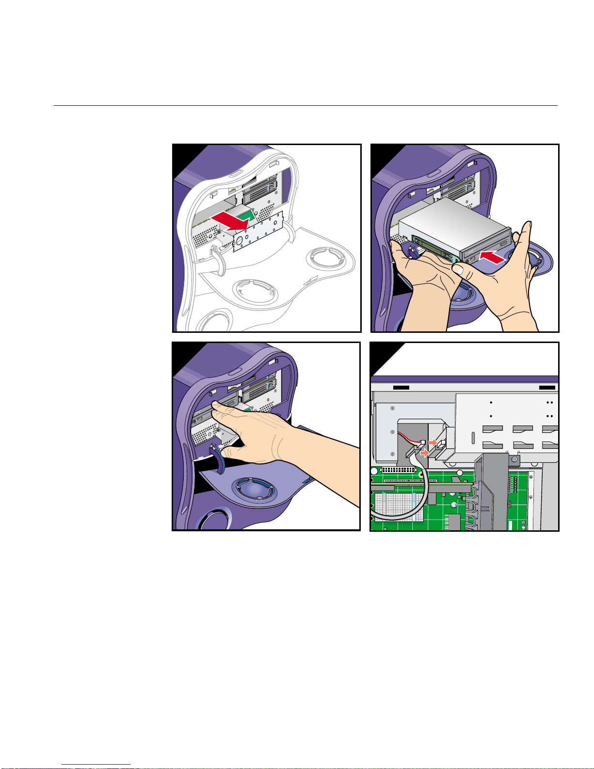
Installing or Removing the DVD-ROM Drive
A
B
DC
Figure 3-14 Installing the DVD-ROM Drive.
This completes the DVD_ROM drive installation. To return the workstation to service,
see “Returning the Workstation to Service” on page 57.
007-4564-001 73

3: Maintenance and Upgrade Procedures
Removing the DVD-ROM Drive
Follow these steps to remove the DVD-ROM drive:
Note: You must remove the drive shroud before you can remove the DVD-ROM drive.
1. Disconnect the IDE and power cables from the rear of the DVD-ROM drive.
2. Squeeze the tabs on the drive rails against the sides of the drive. Then slide the drive
out of the drive cage (see Figure 3-15).
74 007-4564-001

A
Installing or Removing the DVD-ROM Drive
Power connector
Data connector
CB
Figure 3-15 Removing the DVD-ROM Drive
3. If you are replacing the drive with a new drive, refer to “Installing the DVD-ROM
Drive” on page 71. If you are not replacing the DVD-ROM drive, install a metal
drive bay blanking plate in the DVD-ROM drive bay and a plastic blanking plate in
the drive shroud to ensure proper airflow.
007-4564-001 75

3: Maintenance and Upgrade Procedures
This completes the removal of the DVD-ROM drive. To return the workstation to service,
refer to “Returning the Workstation to Service” on page 57.
Replacing the IO9 Board
The IO9 board provides basic I/O functions for the workstation. It also provides
connectivity between the hard-disk drives, DVD-ROM drive, and the interface board.
The following instructions show you how to remove and install the IO9 board:
• “Removing the IO9 Board” on page 76
• “Installing the IO9 Board” on page 78
Note: If you remove the IO9 board, you must install a replacement IO9 board. The
workstation will not function without the IO9 board installed.
Note: If you have not already done so, prepare your system for service. Refer to
“Preparing the Workstation for Service” on page 49. In order to replace the IO9 board,
you must remove the left side panel.
Removing the IO9 Board
Follow these steps to remove the IO9 board:
76 007-4564-001

Replacing the IO9 Board
1. Disconnect the SCSI and IDE cables from the IO9 board. Then loosen the PCI
retention strap (see Figure 3-16).
IDE connector
SCSI connector
IO9 retention strap
Figure 3-16 Disconnecting the Cables and Retention Strap
2. Remove the three screws that secure the PCI gate. Then open the PCI gate (see
Figure 3-17).
R
R
R
R
R
R
R
PCI gate
Figure 3-17 Opening the PCI Gate
R
R
R
R
R
R
R
007-4564-001 77

3: Maintenance and Upgrade Procedures
3. Gently grasp both ends of the IO9 board. Then lift straight up until it clears the PCI
slot. Tilt the front end of the IO9 board upward until it clears the edge of the chassis.
Then remove the IO9 board from the enclosure and place it in a safe location (see
Figure 3-18).
R
R
Figure 3-18 Removing the IO9 Board
This completes the IO9 board removal. To install a new IO9 board, proceed to the next
section.
Installing the IO9 Board
Follow these steps to install a replacement IO9 board:
78 007-4564-001
 Loading...