


SGI 1100 Server
Maintenance a nd Upgrade Guide
007-4047-001

CONTRIBUTORS
Written by Eric Zamost et al
Illustrated by D an Young
Edited by Connie Boltz
Production by Chrystie Danzer
Engineering contributions by David Bertrand, Jagdish Bhavsar, Kunnau Chen, and Charles Skandalis.
COPYRIGHT
© 2001 Silicon Graphics , In c. A ll rights reserved; provided portions m ay be c op y right in third parties, as indicated e lsewhere herein. No
permission is granted to copy, distribute, or create der ivativ e works f r om the content s of thi s elect roni c docume ntati on in any manner, in whole
or in part, without the prior written permission of Silicon Graphics, Inc.
LIMITED RIGHTS LEGEND
The electronic (soft ware) version of thi s document was developed at private expense; if acquir ed under an agreement w ith the USA go vernment
or any contractor thereto, it is acquired as "co mmercial computer s oftware" subject to the p rovisions of its applicable license agreement, as
specified in (a) 48 CFR 12.212 of the FAR; or, if acquired for Dep artment of Defense units, (b) 48 CFR 227-7202 of the DoD FAR Supplement; or
sections succeeding thereto. Con t rac t or/manufacturer is Silicon Graph ic s, In c. , 1600 Amphitheatre Pkwy 2E, Mountain View, CA 94043-1351.
TRADEMARKS AND ATTRIBUTIONS
Silicon Graphics is a registered trademark and SGI and the SGI logo are trademar ks of S ili con Graphics, Inc. Linux is a registered trade m ark of
Linus Torvalds. MS-DOS, Windows, and Windows NT are registered trademarks of Microsoft Cor p oration.
Cover Design By S a rah Bolles, Sarah Bolles Design, and Dany Galgani, SGI Technical Publicatio n s .

Record of Revision
Version Description
001 January, 2001
Initial Revision
007-4047-001 iii


Contents
Figures . . . . . . . . . . . . . . . . . . . . . . . . . . ix
Tables . . . . . . . . . . . . . . . . . . . . . . . . . .xiii
About Th is Guide. . . . . . . . . . . . . . . . . . . . . . . xv
Obtaining Publications . . . . . . . . . . . . . . . . . . . . . xv
Reader Comments. . . . . . . . . . . . . . . . . . . . . . . xv
1. Chassis Description . . . . . . . . . . . . . . . . . . . . . . 1
Processors . . . . . . . . . . . . . . . . . . . . . . . . . 2
Memory. . . . . . . . . . . . . . . . . . . . . . . . . . 2
System Chipsets . . . . . . . . . . . . . . . . . . . . . . . 3
Server Works LE North and South Bridge. . . . . . . . . . . . . . . 3
LAN Subsystem . . . . . . . . . . . . . . . . . . . . . . 3
Video Subsystem . . . . . . . . . . . . . . . . . . . . . . 3
Expansion Slot. . . . . . . . . . . . . . . . . . . . . . . 3
System Block Diagram . . . . . . . . . . . . . . . . . . . . . 4
Chassis Front Controls and Indicators . . . . . . . . . . . . . . . . . 5
Rear Panel I/O Ports and Features . . . . . . . . . . . . . . . . . . 7
Internal Components . . . . . . . . . . . . . . . . . . . . . . 9
Hardware Management Support . . . . . . . . . . . . . . . . . . 11
Power Management . . . . . . . . . . . . . . . . . . . . . . 11
IPMI (Intelligent Platform Management Interface) . . . . . . . . . . . . . 13
Intelligent Platform Management Interface (IPMI) . . . . . . . . . . . . 13
Intelligent Platform Management Bus (IPMB). . . . . . . . . . . . . . 13
Intelligent Chassis Management Bus (ICMB) . . . . . . . . . . . . . . 14
Baseboard Management Controller (BMC) . . . . . . . . . . . . . . 14
007-4047-001 v

Features Summary . . . . . . . . . . . . . . . . . . . . . . . 15
2. Removing and Replacing System Components . . . . . . . . . . . . . . 19
Tools and Supplies Needed . . . . . . . . . . . . . . . . . . . . 20
ESD Precautions . . . . . . . . . . . . . . . . . . . . . . . 20
Opening the Chassis . . . . . . . . . . . . . . . . . . . . . . 21
Removing the Chassis Cover. . . . . . . . . . . . . . . . . . . 21
Installing the Chassis Cover . . . . . . . . . . . . . . . . . . . 23
Removing and Installing the Front Panel . . . . . . . . . . . . . . . 24
Replacing the Link Bar and the Riser Card . . . . . . . . . . . . . . . . 25
Removing the Link Bar . . . . . . . . . . . . . . . . . . . . 25
Installing the Link Bar. . . . . . . . . . . . . . . . . . . . . 27
Removing the Riser Card . . . . . . . . . . . . . . . . . . . . 28
Installing the Riser Card . . . . . . . . . . . . . . . . . . . . 29
Installing an Expansion Board . . . . . . . . . . . . . . . . . . . 30
Replacing the Chassis Fan Subsystem . . . . . . . . . . . . . . . . . 32
Removing the Chassis Fan Cage. . . . . . . . . . . . . . . . . . 32
Installing the Chassis Fan Cage . . . . . . . . . . . . . . . . . . 34
Replacing Chassis Fans . . . . . . . . . . . . . . . . . . . . 36
Replacing the Rear Chassis Blowers . . . . . . . . . . . . . . . . . . 37
Removing a Rear Chassis Blower . . . . . . . . . . . . . . . . . 37
Installing a Rear System Blower . . . . . . . . . . . . . . . . . . 39
Replacing the Cable Modules . . . . . . . . . . . . . . . . . . . . 40
Replacing the LED Cable Module . . . . . . . . . . . . . . . . . 40
Replacing the Power Switch Cable Module . . . . . . . . . . . . . . 42
Replacing the USB Daughterboard Cable Module. . . . . . . . . . . . . 45
Replacing the Intrusion Alert Microswitch Cable Module . . . . . . . . . . 48
Replacing Removable-Media Devices . . . . . . . . . . . . . . . . . 51
Removing the Diskette Drive/CD-ROM Drive Module . . . . . . . . . . . 51
Installing the Diskette Drive/CD-ROM Drive Module . . . . . . . . . . . 54
Replacing the Diskette Drive . . . . . . . . . . . . . . . . . . . 56
Replacing the CD-ROM Drive . . . . . . . . . . . . . . . . . . 58
vi 007-4047-001

Replacing a Hard Drive . . . . . . . . . . . . . . . . . . . . . 63
Removing a Hard Drive . . . . . . . . . . . . . . . . . . . . 63
Installing a Hard Disk Drive. . . . . . . . . . . . . . . . . . . 68
Replacing the Power Supply Module . . . . . . . . . . . . . . . . . 71
Removing the Power Supply Module . . . . . . . . . . . . . . . . 71
Installing the Power Supply Module . . . . . . . . . . . . . . . . 76
Removing a Processor. . . . . . . . . . . . . . . . . . . . . . 81
Installing a Processor . . . . . . . . . . . . . . . . . . . . . . 83
Installing a Processor Terminator Board . . . . . . . . . . . . . . . . 86
Removing a DIMM . . . . . . . . . . . . . . . . . . . . . . 87
Installing a DIMM . . . . . . . . . . . . . . . . . . . . . . . 89
Replacing the CMOS Battery. . . . . . . . . . . . . . . . . . . . 91
Replacing the System Board . . . . . . . . . . . . . . . . . . . . 92
3. Troubleshooting . . . . . . . . . . . . . . . . . . . . . . . 97
Error Beep Definitions . . . . . . . . . . . . . . . . . . . . . 98
Power-On Self-Test (POST) Checkpoints List . . . . . . . . . . . . . . . 99
POST Error Messages . . . . . . . . . . . . . . . . . . . . . .104
Error Message for NMI and Warning Message . . . . . . . . . . . . . .107
IPMI Event Log . . . . . . . . . . . . . . . . . . . . . . .108
Index of Error Symptoms. . . . . . . . . . . . . . . . . . . . .1 14
A. Technical Specifications . . . . . . . . . . . . . . . . . . . . .115
Physical and Environmental Specification . . . . . . . . . . . . . . . .115
Power Consumption . . . . . . . . . . . . . . . . . . . . . 1 16
Thermal Dissipation . . . . . . . . . . . . . . . . . . . . .116
Jumper and Connector Information . . . . . . . . . . . . . . . . . .117
Hardware Specifications and Configurations . . . . . . . . . . . . . . .122
B. Updating the BIOS Firmware . . . . . . . . . . . . . . . . . . .133
BIOS Flashing . . . . . . . . . . . . . . . . . . . . . . . .133
C. Port Pinouts . . . . . . . . . . . . . . . . . . . . . . . .135
PS/2 Keyboard Port . . . . . . . . . . . . . . . . . . . . . . 1 36
PS/2 Mouse Port . . . . . . . . . . . . . . . . . . . . . . .137
VGA Port (DB15 HD) . . . . . . . . . . . . . . . . . . . . . .138
007-4047-001 vii

Serial Ports . . . . . . . . . . . . . . . . . . . . . . . . 139
USB Ports . . . . . . . . . . . . . . . . . . . . . . . . 140
Ethernet Ports (RJ45) . . . . . . . . . . . . . . . . . . . . . 141
Index . . . . . . . . . . . . . . . . . . . . . . . . Index-143
viii 007-4047-001

Figures
Figures
Figure 1-1 System Block Diagram. . . . . . . . . . . . . . 4
Figure 1-2 Front Controls and Indicators. . . . . . . . . . . . 5
Figure 1-3 Rear Panel I/O Ports and Features . . . . . . . . . . 7
Figure 1-4 SGI 1100 Server Internal Components . . . . . . . . . 9
Figure 2-1 Removing the Chassis Cover . . . . . . . . . . . . 22
Figure 2-2 Placing the Chassis Cover on the Chassis . . . . . . . . 23
Figure 2-3 Removing the Front Panel. . . . . . . . . . . . . 24
Figure 2-4 Removing the Link Bar . . . . . . . . . . . . . 26
Figure 2-5 Installing the Link Bar . . . . . . . . . . . . . . 27
Figure 2-6 Detaching the Riser Card from the Link Bar . . . . . . . 28
Figure 2-7 Installing the Riser Card on the Link Bar . . . . . . . . 29
Figure 2-8 Removing the Expansion Slot Filler Plate . . . . . . . . 30
Figure 2-9 Inserting the Expansion Card into the Riser Card . . . . . . 31
Figure 2-10 Removing the Chassis Fan Cage . . . . . . . . . . . 33
Figure 2-11 Installing the Chassis Fan Cage . . . . . . . . . . . 35
Figure 2-12 Removing the Chassis Fan . . . . . . . . . . . . 36
Figure 2-13 Location of the Rear System Blower Cable Connectors . . . . 38
Figure 2-14 Rear System Blower Securing Screws . . . . . . . . . 39
Figure 2-15 Location of the LED Cable Connectors . . . . . . . . . 40
Figure 2-16 Installing the LED Cable Module. . . . . . . . . . . 41
Figure 2-17 Location of the Power Switch Cable Connector. . . . . . . 42
Figure 2-18 Removing the Power Switch Cable Module. . . . . . . . 43
Figure 2-19 Installing the Power Switch Cable Module . . . . . . . . 44
Figure 2-20 Location of the USB Daughterboard Cable Connector. . . . . 45
Figure 2-21 Removing the USB Daughterboard Cable Module . . . . . . 46
007-4047-001 ix

Figures
Figure 2-22 Installing the USB Daughterboard Cable Module . . . . . . 47
Figure 2-23 Location of the Intrusion Alert Microswitch Cable Connector. . . 48
Figure 2-24 Removing the Intrusion Alert Microswitch Cable Module. . . . 49
Figure 2-25 Installing the Intrusion Alert Microswitch Cable Module . . . . 50
Figure 2-26 Releasing the Signal Cable Retaining Strap . . . . . . . . 51
Figure 2-27 Disconnecting the Drive Module Signal Cables . . . . . . . 52
Figure 2-28 Removing the Drive Module . . . . . . . . . . . . 53
Figure 2-29 Connecting the Drive Module Signal Cables. . . . . . . . 55
Figure 2-30 Removing the Diskette Drive from the Drive Module . . . . . 56
Figure 2-31 Installing the Diskette Drive into the Drive Module . . . . . 57
Figure 2-32 Removing the CD-ROM Drive Converter Board . . . . . . 58
Figure 2-33 Removing the CD-ROM Drive from the Drive Module. . . . . 59
Figure 2-34 Installing the CD-ROM Drive into the Drive Module . . . . . 60
Figure 2-35 Securing the CD-ROM drive to the Drive Module . . . . . . 61
Figure 2-36 Removing Hard Drive Cables . . . . . . . . . . . . 64
Figure 2-37 Removing Two of Four Hard Disk Drive Screws . . . . . . 65
Figure 2-38 Removing the Hard Disk Drive . . . . . . . . . . . 66
Figure 2-39 Installing the Hard Disk Drive. . . . . . . . . . . . 69
Figure 2-40 Location of the System Board Power Supply Connector . . . . 71
Figure 2-41 Location of the Hard Drive Power Supply Connectors . . . . . 72
Figure 2-42 Removing the Air Guide Plate. . . . . . . . . . . . 73
Figure 2-43 Removing the Plastic Plenum . . . . . . . . . . . . 74
Figure 2-44 Removing the Power Supply Module. . . . . . . . . . 75
Figure 2-45 Installing the Power Supply Module . . . . . . . . . . 77
Figure 2-46 Installing the Plastic Plenum . . . . . . . . . . . . 78
Figure 2-47 Installing the Metal Air Guide Plate . . . . . . . . . . 79
Figure 2-48 Removing a Processor . . . . . . . . . . . . . . 82
Figure 2-49 Installing the Processor. . . . . . . . . . . . . . 84
Figure 2-50 Location of the Fan/Heatsink Cable Connector . . . . . . . 85
Figure 2-51 Installing a Processor Terminator Board . . . . . . . . . 86
Figure 2-52 Removing a DIMM . . . . . . . . . . . . . . . 88
Figure 2-53 Installing a DIMM . . . . . . . . . . . . . . . 90
Figure 2-54 Replacing the CMOS Battery . . . . . . . . . . . . 91
x 007-4047-001

Figures
Figure 2-55 Removing the System Board . . . . . . . . . . . . 93
Figure 2-56 Installing the System Board . . . . . . . . . . . . 94
Figure 3-1 Threshold Setting Levels . . . . . . . . . . . . .113
Figure A-1 System Board Layout . . . . . . . . . . . . . .117
Figure A-2 CN15 Connector Settings . . . . . . . . . . . . .121
Figure C-1 Keyboard Port Pinout . . . . . . . . . . . . . .136
Figure C-2 Mouse Port Pinout . . . . . . . . . . . . . . .137
Figure C-3 DB15 HD Port Pinout . . . . . . . . . . . . . .138
Figure C-4 Serial Port Pinout . . . . . . . . . . . . . . .139
Figure C-5 USB Port Pinout . . . . . . . . . . . . . . .140
Figure C-6 Ethernet Port Pinout . . . . . . . . . . . . . .141
007-4047-001 xi


Tables
Tables
Table 1-1 Front Controls and Indicators. . . . . . . . . . . . 5
Table 1-2 Rear Panel I/O Ports and Features . . . . . . . . . . 7
Table 1-3 Internal Components . . . . . . . . . . . . . . 9
Table 1-4 Power-Saving Mode Characteristics List . . . . . . . . 11
Table 3-1 Error Beep Definitions . . . . . . . . . . . . . . 98
Table 3-2 POST Checkpoints List . . . . . . . . . . . . . 99
Table 3-3 POST Error Messages . . . . . . . . . . . . . .104
Table 3-4 NMI Error Messages and Warning Messages . . . . . . .107
Table 3-5 IPMI System Event Log . . . . . . . . . . . . .108
Table 3-6 Index of Error Symptoms . . . . . . . . . . . . .1 14
Table A-1 SGI 1100 Server Physical Specification . . . . . . . . .115
Table A-2 System Board Layout . . . . . . . . . . . . . .118
Table A-3 Major Chips on System Board . . . . . . . . . . .122
Table A-4 Processor Specifications . . . . . . . . . . . . .122
Table A-5 BIOS Specifications. . . . . . . . . . . . . . .123
Table A-6 BIOS Hotkey List . . . . . . . . . . . . . . .123
Table A-7 Cache Memory Specifications . . . . . . . . . . . .124
Table A-8 VRM Specifications. . . . . . . . . . . . . . .124
Table A-9 System Memory Specifications . . . . . . . . . . .125
Table A-10 Memory Combinations . . . . . . . . . . . . .125
Table A-11 LAN Interface Specifications . . . . . . . . . . . .126
Table A-12 VGA Interface Specifications . . . . . . . . . . . .126
Table A-13 IDE Interface Specifications . . . . . . . . . . . .126
Table A-14 Diskette Drive Interface Specifications . . . . . . . . .127
Table A-15 Serial Port Specifications . . . . . . . . . . . . .127
007-4047-001 xiii

Tables
Table A-16 Memory Address Map . . . . . . . . . . . . . 128
Table A-17 I/O Address Map . . . . . . . . . . . . . . 128
Table A-18 IRQ Assignment Map . . . . . . . . . . . . . 131
Table A-19 PCI Interrupt Routing 1 . . . . . . . . . . . . 131
Table A-20 PCI Interrupt Routing 2 . . . . . . . . . . . . 132
Table A-21 On-board Device ID & IRQ Map Table . . . . . . . . 132
Table C-1 Keyboard Port Pinout . . . . . . . . . . . . . 136
Table C-2 Mouse Port Pinout . . . . . . . . . . . . . . 137
Table C-3 DB15 HD Port Pinout . . . . . . . . . . . . . 138
Table C-4 Serial Port Pinout . . . . . . . . . . . . . . 139
Table C-5 USB Port Pinout . . . . . . . . . . . . . . . 140
Table C-6 Ethernet Port Pinout . . . . . . . . . . . . . 141
xiv 007-4047-001

About This Guide
This guide contains a detailed description of the SGI 1100 server chassis, and provides
information on removing and installin g system components.
The following topics are covered:
• Chapter 1, “Chassis Description”
• Chapter 2, “Removing and Replacing System Components”
• Chapter 3, “Troubleshooting”
• Appendix A, “Technical Specifications”
• Appendix B, “Updating the BIOS Firmware”
• Appendix C, “P ort Pinouts”
An Index completes this guide.
Obtaining Publications
To obtain SGI documentation, se e the SGI Tec hnical Publications Library at
http://techpubs.sgi.com.
Reader Comments
If you have comments about the technical accuracy, content, or organization of this
document, please contact SGI. Be sure to include the title and document number of the
manual with your comments. (Online, the document number is located in the front
matter of the manual. In printed manuals, the document number is located at the bottom
of each page.)
You can contact SGI in any of the following ways:
007-4047-001 xv

About This Guide
• Send e-mail to the following address:
techpubs@sgi.com
• Use the Feedback option on the Technical Publications Library Web page:
http://techpubs.sgi.com
• Contact your customer service representative and ask that an incident be filed in the
SGI incident tracking system.
• Send mail to the following address:
Technical Publications
SGI
1600 Amphitheatre Pkwy., M/S 535
Mountain View, California 94043-1351
• Send a fax to the attention of “Technical Publications” at +1 650 932 0801.
SGI values your comments and will respond to them promptly.
xvi 007-4047-001

Chapter 1
1. Chassis Description
The SGI 1100 server is a 1U, high-density, rackmountable, PCI bus-based dual-processor
system built on an extended ATX baseboard. It comes with two socket 370 processor
sockets utilizing one or two Intel Pentium III processors integrated with the Server
Works LE north and OSB4 south bridge chipsets. The system board integrates two Intel
82559 10/100 Mbps PCI E the rn et chi ps et s that s u pports WOL (w ak e on LA N) fo r bett er
remote site management.
For expandability , the system includes one 64-bit/66-MHz PCI bus slot and four DIMM
slots that allow memory installation to a maximum of 2 GB using four 512-MB SDRAM
(synchronous DRAM) DIMMs.
For connectivity , the system supports four USB (Universal Serial Bus) connectors, a video
port, two LAN ports, and other standard features such as two serial ports, a diskette
drive interface, and two embedded IDE hard disk interfaces.
The system is fully compatible with Redhat Linux 6.2, Window s NT 4.0, and Windows
2000 Advanced Server OS.
This chapter contains a detailed description of the SGI 1100 server system components.
007-4047-001 1

1: Chassis Description
Processors
Memory
The Pentium III processor implements Dynamic Execution performance, a
multi-transaction system bus, and Intel MMX media enhancement technology. Also, it
offers Streaming SIMD (Single Instruction Multiple Data) extensio ns, which are 70 new
instructions enabling advanced imaging, 3D, streaming audio and video, and speech
recognition applications. The Pentium III processor delivers higher performance than the
previous Pentium processor while maintaining bin ary compatibility with all previous
Intel Architecture processors.
This system board supports 133-MHz GTL+ host bus frequencies for Pentium III
processors running at 800 MHz and above.
The four DIMM sockets on board allow memory upgrade to a maximum of 2 GB using
four 512-MB SDRAM (Synchronous DRAM) DIMMs. (The DIMM sockets also allow
1024 MB for a maximum upgrade of 4 GB in future models.) For data integrity, the
default setting of the ECC (error-correcting code) function of the memory system in BIOS
is enabled.
Note: Only 3.3-volt SDRAM DIMMs should be used. 5-volt memory devices are not
supported.
The system board supports 133-MHz registered SDRAM; 66-MHz SDRAM is not
supported.
2 007-4047-001

System Chipsets
Server Works LE North and South Bridge
The Server W orks LE north chipset incorporated as a north bridge is in charge of the host
bus interfacing and memory bus control. The memory bus control supports PC-133
SDRAM registered ECC DIMMs up to a total of 4 GB. The north bridge provides one
64-bit PCI bus running at 66 MHz.
The south bridge subset provides the legacy ISA interface, USB port, AT A33, and System
Management Bus (SMB). The BMC (Bas eboard Mana gement Control) w as embedded on
the motherboard and connected with the south bridge to provide the ASM and RDM
functions and industry standard IPMI protocol.
LAN Subsystem
Another cost-effective feature for network solution is the integration of Intel’s 82559
10/100 Mbps Fast Ethernet controller which supports Advanced Configura tion and
Power Interface (ACPI) 1.20A-based power mana gement, wake on Magic Packet, wake
on interesting packet, advanced SMB-based mana geability, Wired for Management
(WfM) 2.0 compliance, IP checksum assist, PCI 2.2 compliance, and PC 98 and PC 99
compliance.
System Chipsets
Video Subsystem
The A TI Rage XL harbors 2D and 3D display capabilities that bring life to any multimedia
and work applications. It also supports hardware DVD decoding. With r emarkable color
depths and high resolutions of up to 1600x1200, it enhances every visual experience on
your system.
The on-board ATI Rage XL chipset comes with 4 MB of video memory.
Expansion Slo t
The system board has one 64-bit/66-MHz PCI bus slot with a riser card.
007-4047-001 3

1: Chassis Description
System Block Diagr am
Figure 1-1 shows a block diagram of the SGI 1100 system board components.
Socket
Coppermine
Front Side Bus @ 133MHz
Secondary
PCI Bus
(64b/66MHz)
PC Bus
RDM VGA
USB
E-IDE
Ultra 33
CNB30LE
Host Bridge
OSB4
PCI-ISA bridge
Up to 1.0 GB/s
Primary PCI Bus (32b/33MHz)
ISA Bus
Socket
Coppermine
133MHz
Memory
Bandwidth
Intel
82559
LAN
Up to
2 GB SDRAM
Intel
82559
LAN
Figure 1-1 System Block Diagram
4 007-4047-001
BIOS
Super I/O
(SMC)

Chassis Front Controls and Indicators
This section describes the front controls and indicators of the SGI 1100 server, as shown
in Figure 1-2.
Figure 1-2 Front Controls and Indic ator s
Table 1-1 describes the front controls and indicators that are indicated in Figure 1-2.
Table 1-1 Front Controls and Indic ator s
Chassis Front Controls and Indicators
No. Item
1 Slim-type floppy disk drive LED
2 Slim-type floppy disk drive
3 Slim-type floppy disk drive eject button
4 Event LED
5 Hard disk drive access LED
6 Power LED
7 LAN 2 access LED
8 LAN 1 access LED
9 Power button
10 Metal handle
11 USB ports (2 ports)
007-4047-001 5

1: Chassis Description
Table 1-1 (continued) Front Controls and Indicators
No. Item
12 Slim-type CD-ROM drive emergency eject hole
13 Slim-type CD-ROM drive eject button
14 Slim-type CD-ROM drive LED
The general event LED indicates the following occurrences:
• Temperature, voltage, system fan, or fuse events.
• CPU IERR and Thermtrip error.
• System fan or power supply unplug .
• Removal of top cover.
• Uncorrectable memory error (multiple ECC errors).
• PCI PERR or SERR error.
If all of the preceding events recover, the Baseboard Management Controller (BMC)
should turn off the LED.
Note: The BMC will not turn on the general event LED for BIOS POST, PCI hot plug, and
correctable memory error events.
6 007-4047-001

Rear Panel I/O Ports and Features
This section describes the rear panel I/O ports and other features, as shown in Figure 1-3.
Figure 1-3 Rear Panel I/O Ports and Features
Table 1-2 describes the rear panel I/O ports and featur es th at a re indicated in F i gure 1-3.
Table 1-2 Rear Panel I/O Ports and Features
Rear Panel I/O Ports and Features
No. Item
1 AC power input
2 Ventilation
3Serial port 2
4 PS/2 mouse port
5 Ventilation
6 Ventilation
7Add-on card bracket
8 LAN 2 port (RJ-45)
9 LAN 1 port (RJ-45)
10 USB ports (2 ports)
11 VGA port
007-4047-001 7

1: Chassis Description
Table 1-2 (continued) Rear Panel I/O Ports and Features
No. Item
12 Serial port 1
13 PS/2 keyboard port
8 007-4047-001
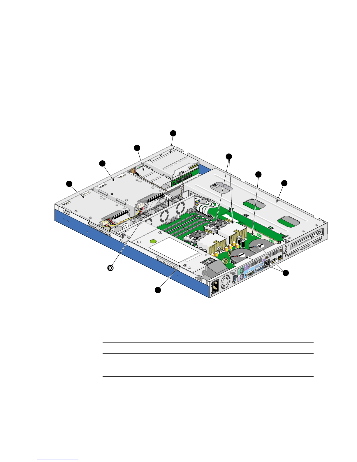
Internal Components
This section describes the location of the main components inside the SGI 1100 server, as
shown in Figure 1-4.
2
1
Internal Components
4
3
5
6
7
8
9
Figure 1-4 SGI 1100 Server Internal Components
Table 1 -3 describes the internal components that are indicated in Figure 1-4.
Table 1-3 Internal Components
No. Item
1 IDE hard disk drive bay
2 IDE hard disk drive bay
007-4047-001 9

1: Chassis Description
Table 1-3 (continued) Internal Components
No. Item
3 Slim-type CD-ROM drive
4 Slim-type floppy disk drive
5 CPUs and fan/heatsinks
6System board
7 PCI expansion card slot and link bar
8 Rear blowers
9 Power supply
10 Housing fans
10 007-4047-001

Hardware Management Support
The system supports the power-management function that conforms to the
power-saving standards of the U.S. Environmental Protection Agency (EP A) Energy Star
program. It also offers Plug-and-Play, which helps users avoid configuration problems
and thus makes the system more user-friendly.
Power Management
T able 1-4 lists the power-saving modes and their respective characteristics. These power
management features are only available if the operating system running on the system
supports them
Table 1-4 Power-Saving Mode Char ac t eristics List
Power-saving mode Characteristics
Device standby mode Independent power management timer for HDD devices (0-15
Hardware Management Support
minutes, time step = 1 mi nute)
Hard disk drive goes into STANDBY mode (for ATA standard
interface)
Disable V-sync to control the VESA DPMS monitor
Resume method: device acti vated (keyboard for DOS, keyboard
and mouse for Windows)
Resume recovery time: 3-5 seconds
007-4047-001 11

1: Chassis Description
Table 1-4 (continued) Power-Saving Mode Characteristics List
Power-saving mode Characteristics
Global standby mode Global power management timer (1-60 minutes)
Hard disk drive goes into STANDBY mode (for ATA standard
interface)
Disable H-sync and V-sync signals to control the VESA DPMS
monitor
Resume recovery time: 7-10 seconds
System suspend mode Independent power management timer (1-60 minutes) or pushing
external switch button
CPU goes into SMM (system management mode)
CPU asserts STPCLK# and goes into the stop grant state
LED on the panel flashes in amber color
Hard disk drive goes into SLEEP mode (for ATA standard
interface)
Disable H-sync and V-sync signals to control the VESA DPMS
monitor
Return to original state by pushing external switch button.
12 007-4047-001

IPMI (Intelligent Platform Management Interface)
IPMI (Intelligent Platform Management Interface)
IPMI is an open standard hardware manageability interface specification. It provides an
architecture that defines how unique devices can all communicate with the CPU in a
standard way.
With IPMI, the CPU only communicates one event to the IPMI event log. The CPU only
“asks” what has changed since the last time it asked. Every device communicates
directly, through IPMI, to the event log, which is used to record, in a consistent way, all
status events for the unique device. This simplifies the agent-handling routine. The
system only needs a single agent, and it does not need to be changed when you change
from five devices to manage, for example, to six. And the system does not need to change
the way the CPU checks the event log when a new device is added to the system; it
always checks in the same way, whether there is one device or 100 devices. With IPMI,
use of the CPU is minimized, so overall system performance improves.
The following are the four elements of IPMI, each of which is described in the sections
that follow:
• Intelligent Platform Management Interface
• Intelligent Platform Management Bus
• Intelligent Chassis Management Bus
• Baseboard Management Controller
Intelligent Platform Management Interface (IPMI)
IPMI is the specification for the management controller command sets, including
command sets for sensors, event logs, and sensor data record access. It is also the
specification for the data formats, including sens or d ata records, event log entries, and
FRU inventory information. IPMI is also the name used for the overall standardization
effort.
Intelligent Platform Management Bus (IPMB)
IPMB is the I2C-based, multi-master bus used fo r intra -ch assis communication with
“satellite” management controllers. Here sensor devices and cards with IPMI bus access
can be added to the IPMI standard.
007-4047-001 13

1: Chassis Description
Intelligent Chassis Management Bus (ICMB)
ICMB is the RS-485-based inter-chassis management bus, based on IPMB. It is used for
common chassis and emergency management functions, including power and rese t
control, chassis status, events, and FRU inventory.
Baseboard Management Controller (BMC)
BMC is used to monitor baseboard temperatures and voltages , and to manage the system
event log and non-volatile storage for sensor data records. It provides a system software
interface to the IPMB.
14 007-4047-001

Features Summary
The system has the following major components:
• Processor
• Chipset
• LAN controller
• Memory
Features Summary
Supports dual Pentium III processors installed in a socket 370 running a 133-MHz
Front Side Bus (FSB).
ServerWorks ServerSet III LE chipset consists of CNB30LE (Champ North Bridge)
and OSB4 (Open South Bridge) is in charge of the host interfacing, memory system
control, PCI interfacing, and data steering.
Two o n-boa rd Intel 82559 10/ 100-Mb/s PCI LAN controllers.
The CNB30LE champ north bridge consists of a system memory controller
integrated with four DIMM so ckets that supp o rt 128-, 512- an d 1024-MB (in the
future) registered ECC SDRAM DIMMs with a maximum memory upgrade of 4 GB
(1024 MB x 4 DIMM modules).
• Cache
256-KB second-level write-back PipeLined-Burst SRAM supported cache on
Pentium III processor.
• Video
On board PCI VGA controller (ATI Rage XL) with 4-MB SDRAM graphics memory
support.
•BIOS
– 512-KB Flash ROM built-in 28SF040A-90 for system and IPMI BIOS.
– Y2K NSTL-compliant.
• Real-time clock (RTC)
– 256-byte battery-backed CMOS RAM.
– Built-in SMC FDC37B787 super I/O controller.
– System clock/calendar with battery backup.
• Power supply
Standard 200W power supply.
007-4047-001 15

1: Chassis Description
• Memory interface
Four DIMM sockets support four PC 133 registered ECC SDRAM modules.
• IDE interface
– E-IDE controller built-in RCC OSB4 (Open South Bridge).
– PCI bus master dual-channel E-IDE interface.
– Provides up to four IDE devices.
– Supports PIO mode 4 transfers up to 16.7 MB/sec, DMA mode 2, and Ultra
DMA33 (33 MB/sec) mode.
• Diskette drive interface
– Compatible with IBM PC AT disk drive system.
– 16-byte data FIFO.
– Data rate and drive control register.
– DMA enable logic.
– 480 addresses, up to eight IRQs, and seven DMA Options.
– Supports 3.5-inch diskette drives.
– Supports 360K-, 720K-, 1.2M-, 1.44M-, 2.88M-byte format, and 250K-, 300K-,
500K-, 1M-, or 2M-bps data transfer rate.
– Supports 3-mode diskette drive.
• PCI Slots
One 64-bit/66-MHz PCI 2.2-compliant PCI slot with a PCI riser card.
• BMC interface
Two 24-pin BMC (Baseboard Management Controller) interfaces.
• I/O APIC device for SMP interrupt support.
• Server management controller chipset.
• Serial port
Two high-speed NS16C550-compatible UART with send/receive 16-byte FIFO
serial ports.
• USB port
Four USB ports support Universal HCI specification for USB 1.0.
• PS/2 keyboard and mouse port
16 007-4047-001

• One external monitor port
• LAN connector
Two RJ-45 jacks for 10BaseT or 100BaseTX LAN connectors.
Features Summary
007-4047-001 17


Chapter 2
2. Removing and Replacing System Components
This chapter contains step-by-step procedures on how to disassemble the SGI 1100 server
system for maintenance and troubleshooting.
Caution: The procedures contained in this chapter should be performed by a qualified
service technician. Do not perform the procedures described in the following sections
unless you are a qualified technician.
The following sections are covered:
•“Tools and Supplies Needed” on page 20.
•“ESD Precautions” on page 20
•“Opening the Chassis” on page 21.
•“Replacing the Link Bar and the Riser Card” on page 25
•“Installing an Expansion Board” on page 30.
•“Replacing the Chassis Fan Subsystem” on page 32.
•“Replacing the Rear Chassis Blowers” on page 37.
•“Replacing the Cable Modules” on page 40.
•“Replacing Removable-Me d ia Devices” on page 51.
•“Replacing a Hard Drive” on page 63.
•“Replacing the Power Supply Module” on page 71.
•“Removing a Proces sor” on page 81.
•“Removing a DIMM” on page 87 .
•“Replacing the CMOS Battery” on page 91.
•“Replacing the System Board” on page 92.
007-4047-001 19

2: Removing and Re placing System Components
Tools and Supplies Needed
To di sassemble the computer, you need the following tools and supplies:
• Wrist grounding strap and conductive mat for preventing electrostatic discharge
• Phillips screwdrivers
Note: The screws for the different components vary in size. During the disassembly
process, group the screws with the corresponding components to avoid mismatches
when putting back the components.
ESD Precautions
Before proceeding with the disassembly procedure, make sure that you do the following:
1. Turn off the power to the system and all peripherals.
2. Unplug the AC adapter and all power and signal cables from the system.
3. Do not remove a component from its ant i static packaging until you are ready to
install it.
4. Wear a wrist grounding strap before handling electronic components. Wrist
grounding straps are available at most electronic component stores.
20 007-4047-001

Opening the Chassis
This section covers the removal and installation of the chassis cover and the front panel.
Note: A microswitch is located under the chassis cover. It detects wheth er the cover is
removed or installed.
Removing the Chassis Cover
Follow these steps to remove the chassis cover:
1. Turn off the power to the system unit and unplug all external cables.
2. Place the system unit on a flat, steady surface.
3. Release the two screw knobs at the rear of the chassis, as shown in Figure 2-1.
Opening the Chassis
007-4047-001 21

2: Removing and Re placing System Components
Figure 2-1 Removing the Chassis Cover
4. Slide the chassis cover towards the rear of the chassis about 1 inch (2.5 cm), as
shown in Figure 2-1.
5. Lift the cover away from the chassis.
22 007-4047-001

Installing the Chassis Cover
Follow these steps to install the chassis cover:
1. Place the system unit on a flat, steady surface.
2. Place the chassis cover on the chassis, so as to insert each of the six retaining pins
into their slots as shown in Figure 2- 2.
Opening the Chassis
Figure 2-2 Placing the Chassis Cover on the Chassis
007-4047-001 23

2: Removing and Re placing System Components
3. Ensure that all six retaining pins are fully engaged into their slots, and then slide the
chassis cover toward the front of the system, as shown in Figure 2-2.
4. Tighten the two screw knobs to secure the chassis cover into place.
Removing and Installing t he Front Panel
To remove the front panel, release the three screws and pull the front panel away from
the chassis as shown in Figure 2-3.
To instal l the f ront panel, tighten the 3 screws to secure the front panel to the chassis.
Figure 2-3 Removing the Front Panel
24 007-4047-001

Replacing the Link Bar and the Riser Card
This section covers the removal and installation of th e link bar and the riser card.
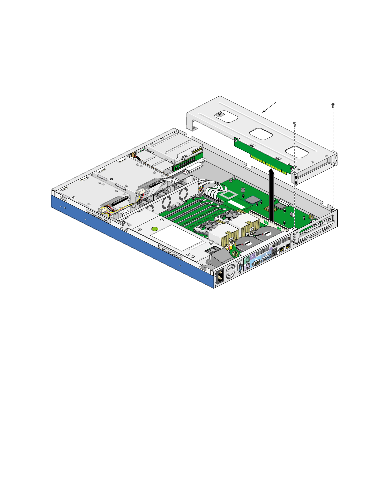
Removing the Link Bar
Follow these steps to remove the link bar:
1. Remove the chassis cover as described in “Removing the Chassis Cover” on
page 21.
2. Remove two screws from the rear panel and pull the link bar away from the chassis
as shown in Figure 2-4.
Replacing the Link Bar and the Riser Card
007-4047-001 25
2: Removing and Re placing System Components
Link bar
Figure 2-4 Removing the Link Bar
26 007-4047-001
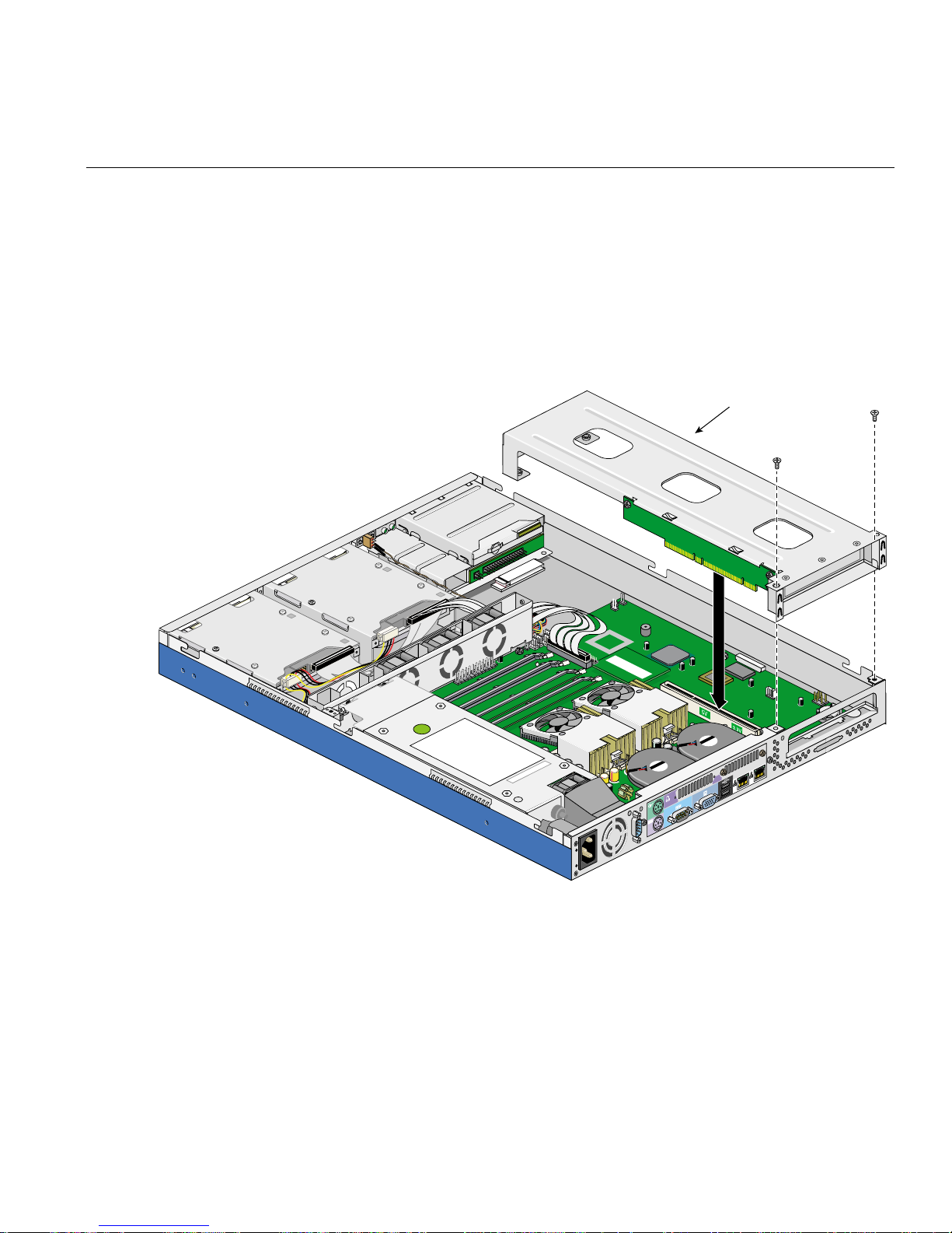
Installing the Link Bar
Replacing the Link Bar and the Riser Card
Follow these steps to install the link bar:
1. Insert the link bar into its slot by pushing the assembly straight into the PCI slot
until it is properly seated, as shown in Figure 2-5.
2. Tighten two screws to the rear panel as shown in Figure 2-5.
Link bar
Figure 2-5 Installing the Link Bar
3. Install the chassis cover as described in “Installing the Chassis Cover” on page 23.
007-4047-001 27

2: Removing and Re placing System Components
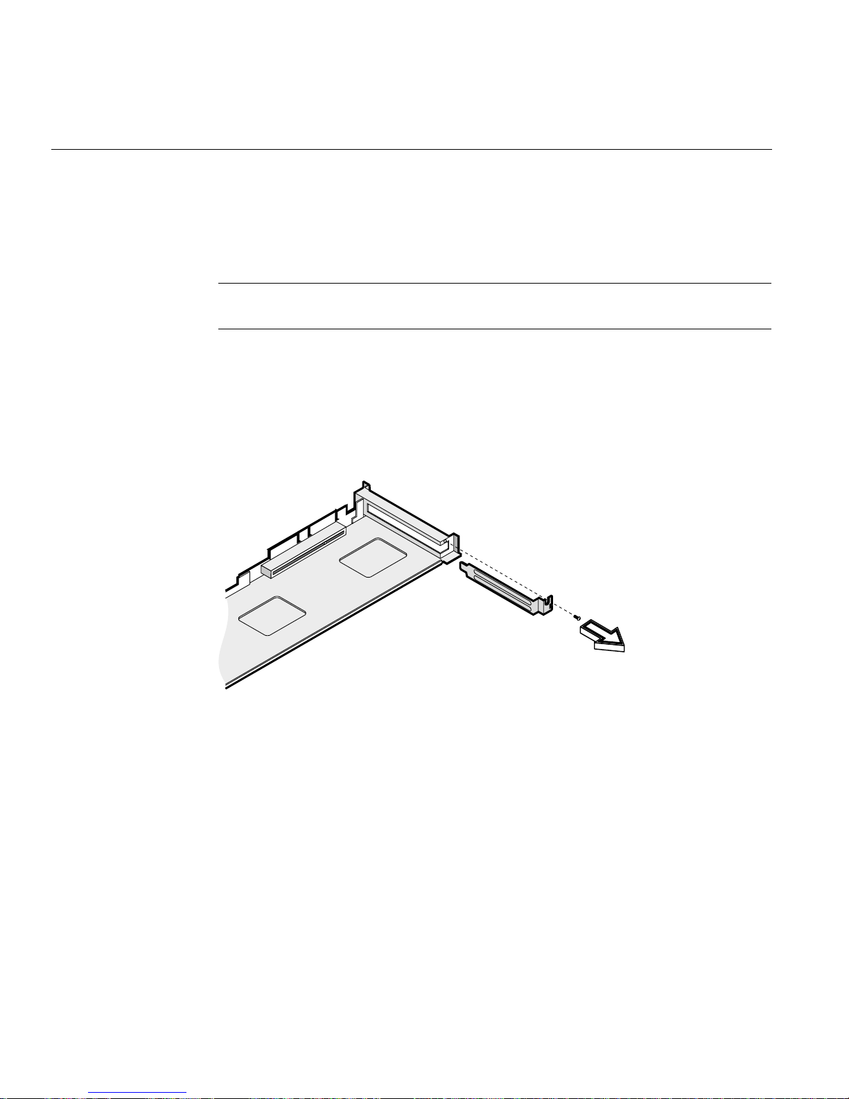
Removing the Riser Card
Follow these steps to remove the riser card from the link bar:
1. Remove the link bar as described in “Removing the Link Bar” on page 25.
2. Remove three screws as shown in Figure 2-6.
Figure 2-6 Detaching the Riser Card from the Link Bar
3. Separate the riser card from the link bar.
28 007-4047-001

Installing the Riser Card
Follow these steps to install the riser card onto the link bar:
1. Place the riser card on the link bar as shown in Figure 2-7.
2. Tighten three screws to secure the riser card to the link bar.
Replacing the Link Bar and the Riser Card
Figure 2-7 Installing the Riser Card on the Link Bar
007-4047-001 29
2: Removing and Re placing System Components
Installing an Expansion Board
Follow these steps to install an expansion board:
Note: The SGI 1100 server system supports only 3.3V or universal PCI cards. 5V PCI
cards are not supported.
1. Remove the chassis cover as described in “Removing the Chassis Cover” on
page 21.
2. Remove the link bar as described in “Removing the Link Bar” on page 25.
3. Remove the expansion slot filler plate as shown in Figure 2-8. Save the screw for
later use.
Figure 2-8 Removing the Expansion Slot Filler Plate
4. Insert the expansion card into the riser card PCI slot by pushing the expansion
board until it is properly seated. Then secure the expansion board to the metal
bracket with a screw, as shown in Figure 2-9.
30 007-4047-001

Installing an Expansion Boa rd
Figure 2-9 Inserting the Expansion Card into the Riser Card
5. Install the link bar assembly into its slot as described in “Installing the Link Bar” on
page 27.
6. Install the chassis cover as described in “Installing the Chassis Cover” on page 23.
007-4047-001 31

2: Removing and Re placing System Components
Replacing the Chassis Fan Subsystem
This section covers the removal and installatio n of the chassis fan cage and chassis fans.
Removing the Chassis Fan Cage
Follow these steps to remove the chassis fan cage:
1. Remove the chassis cover as described in “Removing the Chassis Cover” on
page 21.
2. Disconnect the three fan connectors from the system board as shown in Fi gure 2-10.
3. Remove two screws and pull the chassis fan cage up, as shown in Figure 2-10.
32 007-4047-001

Replacing the Chassis Fan Subsystem
Figure 2-10 Removing the Chassis Fan Cage
007-4047-001 33

2: Removing and Re placing System Components
Installing the Chassis Fan Cage
Follow these steps to install the chassis fan cage:
1. Place the chassis fan cage into the chassis.
Note: Ensure that no cables are pinched between the chassis fan and the chassis during
the installation of the chassis fan cage.
2. Tighten two screws to secure the fan cage to the chassis.
3. Connect the three fan connectors to the system board connectors CN19, CN20, and
CN28, as shown in Figure 2-11.
34 007-4047-001

Replacing the Chassis Fan Subsystem
Figure 2-11 Installing the Chassis Fan Cage
4. Install the chassis cover as described in “Installing the Chassis Cover” on page 23.
007-4047-001 35

2: Removing and Re placing System Components
Replacing Chassis Fans
To remove a chassis fan, gently pull up the chassis fan from the fan cage, as shown in
Figure 2-12.
Figure 2-12 Removing the Chassis Fan
To install a chassis fan, insert the chassis fan into the chassis fan cage.
Note: Ensure th at th e fan you ar e insta llin g is pr ope rly or iente d so as to blow air towar d
the rear of the chassis.
36 007-4047-001

Replacing the Rear Chassis Blowers
This section covers the removal and installation of th e rear chassis blowers.
Removing a Rear Chassis Blower
Follow these steps to remove the rear chassis blowers:
1. Remove the chassis cover as described in “Removing the Chassis Cover” on
page 21.
2. Release two screws to remove the blower as shown in Figure 2-14.
3. Disconnect the blower cables from the connectors on the system board. See
Figure 2-13 for the location of the rear chassis blower cable connectors.
Replacing the Rear Chassis Blowers
007-4047-001 37

2: Removing and Re placing System Components
Cable connection
for right blower
Right blower
Left blower
Figure 2-13 Location of the Rear System Blower Cable Connectors
38 007-4047-001
Cable connection
for left blower

Rear blower
securing screws
Replacing the Rear Chassis Blowers
Figure 2-14 Rear System Blo w e r Sec u ring Screws
Installing a Rear System Blower
Follow theses steps to install each of the rear chassis blowers:
1. Place the blower on its opening on the rear panel as shown in Figure 2-14
2. Connect the rear chassis blower cable to its connector on the system board. The left
blower (the one closest to the power supply) plugs into connector CN13 (which is
underneath the right blower). The right blower plugs into connector CN23 (which is
near the front of the system board). See Figure 2-13 for the locations of the rear
chassis blower cable connectors.
3. Tighten two screws to secure the blower in place.
4. Install the chassis cover as described in “Installing the Chassis Cover” on page 23.
007-4047-001 39

2: Removing and Re placing System Components
Replacing the Cable Modules
This section covers the removal and installation of th e cable modules.
Replacing the LED Cable Module
Follow these steps to remove the LED cable module:
1. Remove the chassis cover as described in “Removing the Chassis Cover” on
page 21.
2. Disconnect all the LED cable connectors from the system board. See Figure 2-15 for
the location of the LED cable connectors.
LED module
LED module
connectors
LED module
connectors
Figure 2-15 Location of the LED Cable Connectors
40 007-4047-001

Replacing the Cable Modules
3. Remove one screw from the LED cable module as shown in Figure2-16.
4. Remove the LED cable module from the system.
Follow these steps to install the LED cable module:
1. Set the LED cable module in place and secure it with one screw as sh own in
Figure 2-16.
LED cable
module
Figure 2-16 Installing the LED Cable Module
2. Connect all the LED cable connectors to the system board. See Figure 2-15 for the
location of the LED cable connectors.
3. Install the chassis cover as described in “Installing the Chassis Cover” on page 23.
007-4047-001 41
2: Removing and Re placing System Components
Replacing the Power Switch Cable Module
Follow these steps to remove the power switch cable module:
1. Remove the chassis cover as described in “Removing the Chassis Cover” on
page 21.
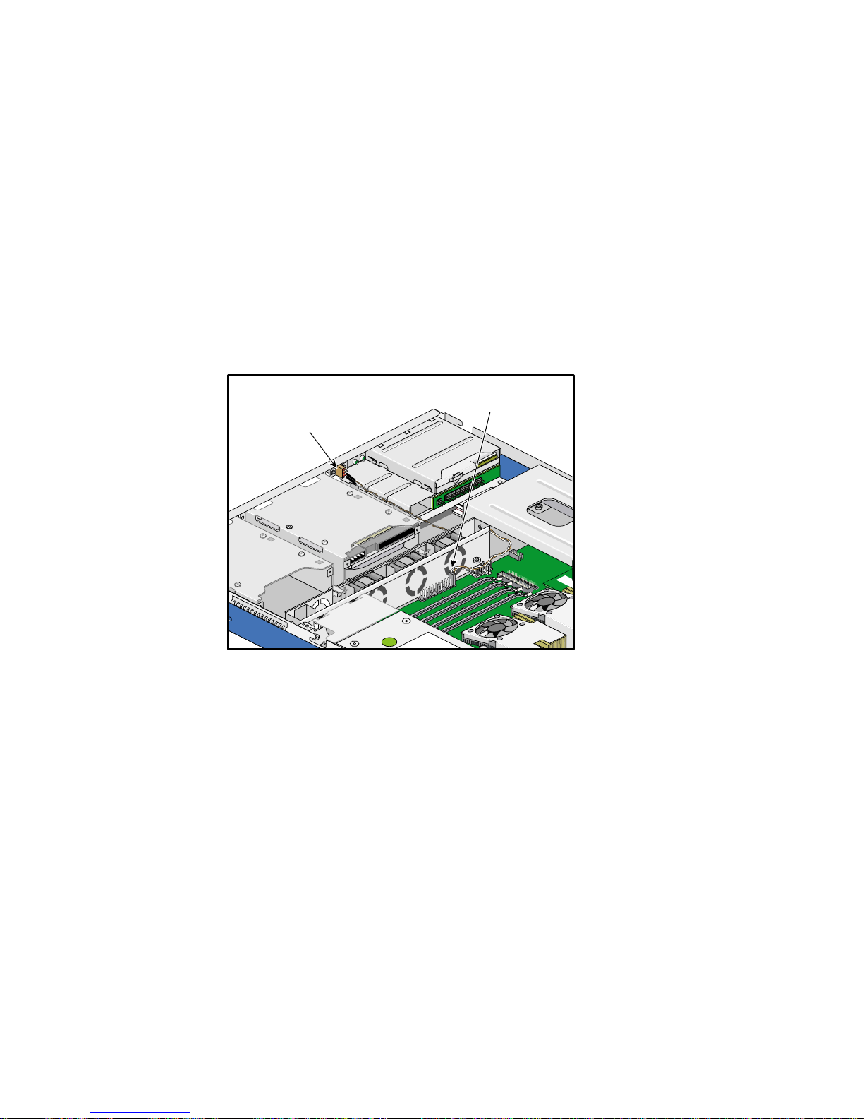
2. Disconnect the power switch cable connector from the system board. See
Figure 2-17 for the location of the power switch cable connector.
Power switch
module
Power switch
connector
Figure 2-17 Location of the Power Switch Cable Connector
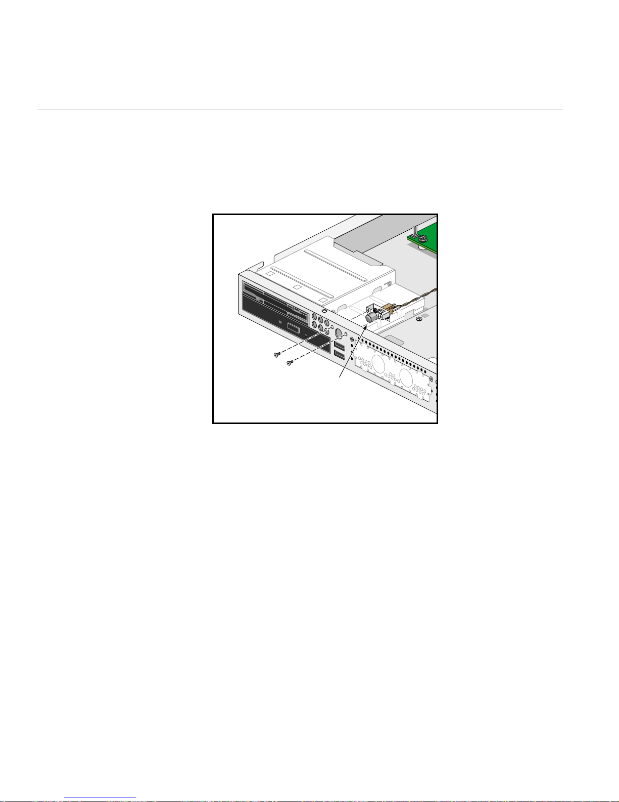
3. Remove two screws from the power switch cable module as sh own in Figure 2-18.
42 007-4047-001

Power switch
module
Figure 2-18 Removing the Power Switch Cable Module
Replacing the Cable Modules
4. Remove the power switch cable module from the system.
007-4047-001 43
2: Removing and Re placing System Components
Follow these steps to install the power switch cable module:
1. Set the power switch cable module in place and secure it with two screws as shown
in Figure 2-19.
Power switch
module
Figure 2-19 Installing the Power Switch Cable Module
2. Connect the power switch cable connector to the system board connector CN15,
pins 1 and 2. See Figure 2-17 for the location of the power switch cable connector.
3. Install the chassis cover as described in “Installing the Chassis Cover” on page 23.
44 007-4047-001
Replacing the USB Daughterboard Cable Module
Follow these steps to remove the USB daughterboard cable module:
1. Remove the chassis cover as described in “Removing the Chassis Cover” on
page 21.
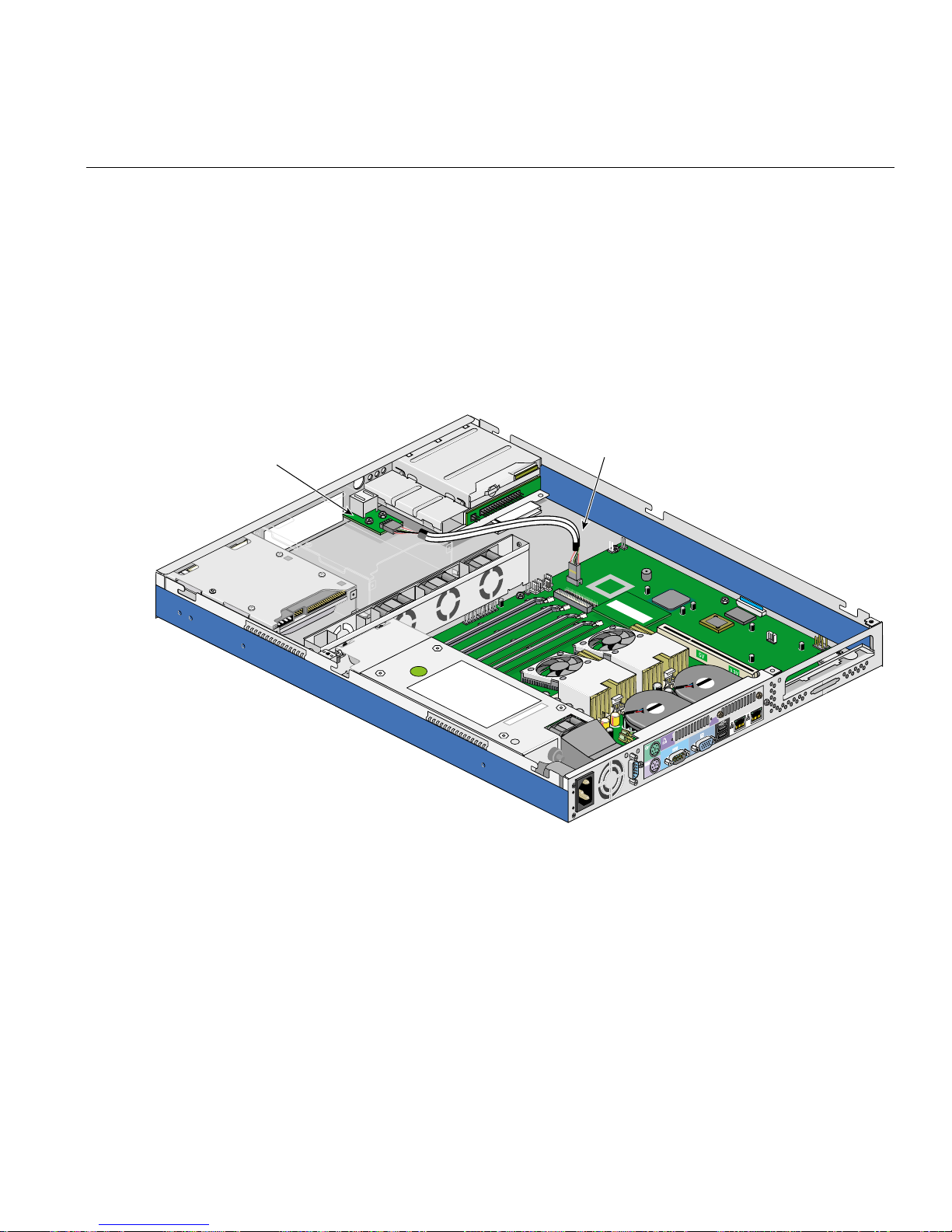
2. Disconnect the USB daughterboard cable connector from the system board. See
Figure 2-20 for the location of the USB daughterboard cable connector.
USB daughterboard
Replacing the Cable Modules
USB daughterboard
cable connector
Figure 2-20 Location of the USB Daughterboard Cable Connector
007-4047-001 45
2: Removing and Re placing System Components
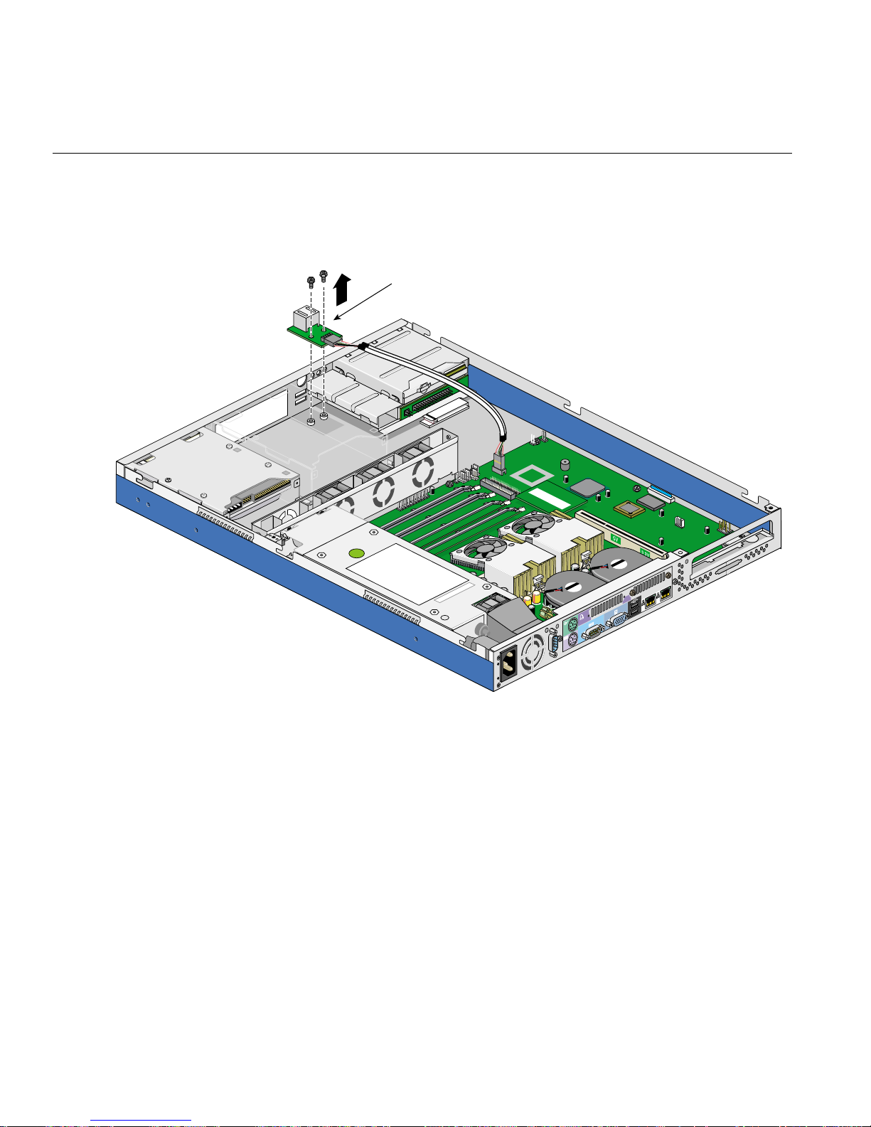
3. Remove two screws from the USB daughterboard cable module as shown in
Figure 2-21.
USB daughterboard
Figure 2-21 Removing the USB Daughterboard Cable Module
4. Remove the USB daughterboard cable module from the system.
46 007-4047-001
Replacing the Cable Modules
Follow these steps to install the USB daughterboard cable module:
1. Set the USB daughterboard cable module in place and secure it with two screws as
shown in Figure 2-22.
USB daughterboard
Figure 2-22 Installing the USB Daughterboard Cable Module
2. Connect the USB daughterboard cable connector to the system board connector
CN30. See Figure 2-20 for the location of the USB daughterboard cable connector.
3. Install the chassis cover as described in “Installing the Chassis Cover” on page 23.
007-4047-001 47

2: Removing and Re placing System Components
Replacing th e Intrusion Alert Microswitch Cable Module
Follow these steps to remove the intrusion alert microswitch cable module:
1. Remove the chassis cover as described in “Removing the Chassis Cover” on
page 21.
2. Disconnect the intrusion alert microswitch cable connector from the system board.
See Figure 2-23 for the location of the intrusion alert microswitch cable connector.
Microswitch cable
connector
Microswitch
Figure 2-23 Location of the Intrusion Alert Microswitch Cable Connector
48 007-4047-001
Replacing the Cable Modules
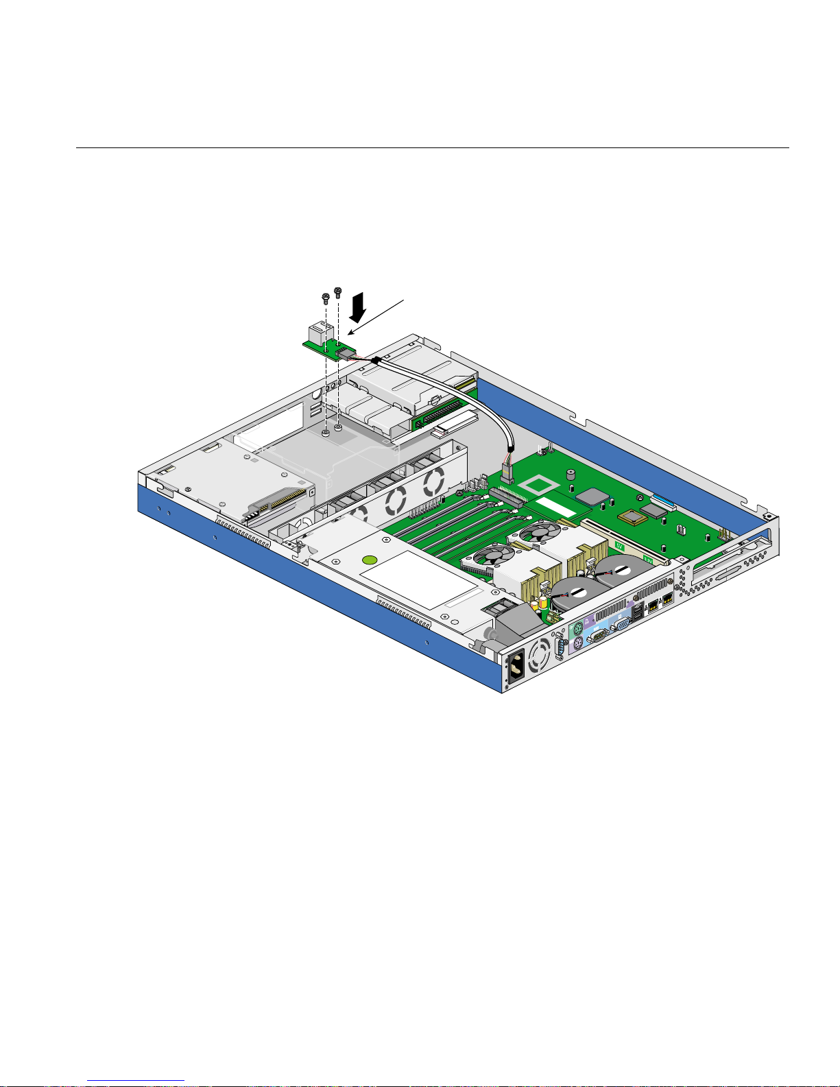
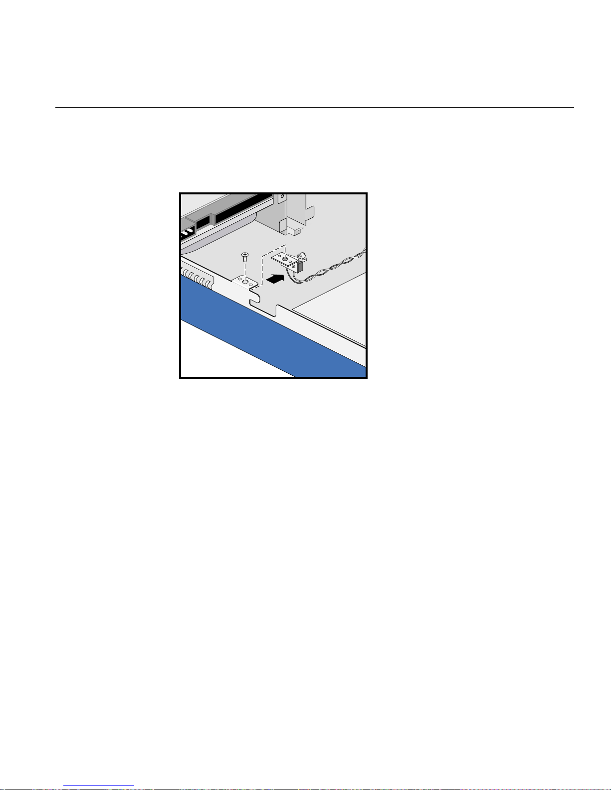
3. Remove the screw from the intrusion alert microswitch cable module as shown in
Figure 2-24.
Figure 2-24 Removing the In tr u sion Alert Micr o switch Cable Module
4. Remove the intrusion alert microswitch cable module from the system as shown in
Figure 2-24.
007-4047-001 49

2: Removing and Re placing System Components
Follow these steps to install the intrusion alert microswitch cable module:
1. Set the intrusion alert microswitch cable module in place and secure it with one
screw as shown in Figure 2-25.
Figure 2-25 Installing the Intrusion Alert Microswitch Cable Module
2. Connect the intrusion alert microswitch cable connector to the system board
connector CN15, pins 19 and 20. See Figure 2-23 for the location of intrusion alert
microswitch cable connector.
3. Install the chassis cover as described in “Installing the Chassis Cover” on page 23.
50 007-4047-001

Replacing Removable-Media Devices
This section covers the removal and installation of the removable-media devices.
Removing the Diskette Drive/CD-ROM Drive Module
Follow these steps to remove the diskette drive/CD-ROM drive module:
1. Remove the chassis cover as described in “Removing the Chassis Cover” on
page 21.
2. Remove the link bar, as described in “Removing the Link Bar” on page 25.
3. Release the signal cable retaining strap, as shown in Figure 2-26.
Retaining strap
Replacing Removable-Media Devices
Figure 2-26 Releasing the Signal Cable Retaining Strap
4. Disconnect the CD-ROM drive signal cable from the CD-ROM drive connector as
shown in Figure 2-27.
007-4047-001 51

2: Removing and Re placing System Components
Note: The CD-ROM drive signal cable is not a standard IDE cable. Instead, the
CD-ROM drive uses a signal cable with 50 conductors, some of which supply power.
5. Disconnect the diskette drive signal cable from the diskette drive connector. To do
so, lift the connector retaining latch and then pull the signal ca ble out of the
connector as shown in Figure 2-27.
Note: If you need to replace the diskette drive signal cable, follow the same
procedure to remove the diskette drive signal cable from the connector on the system
board.
Note: The diskette drive signal cable is not a standard floppy drive cable. Instead,
the diskette drive uses a signal cable with 26 conductors, some of which supply
power.
Figure 2-27 Disconnecting the Drive Module Signal Cables
52 007-4047-001

Replacing Removable-Media Devices
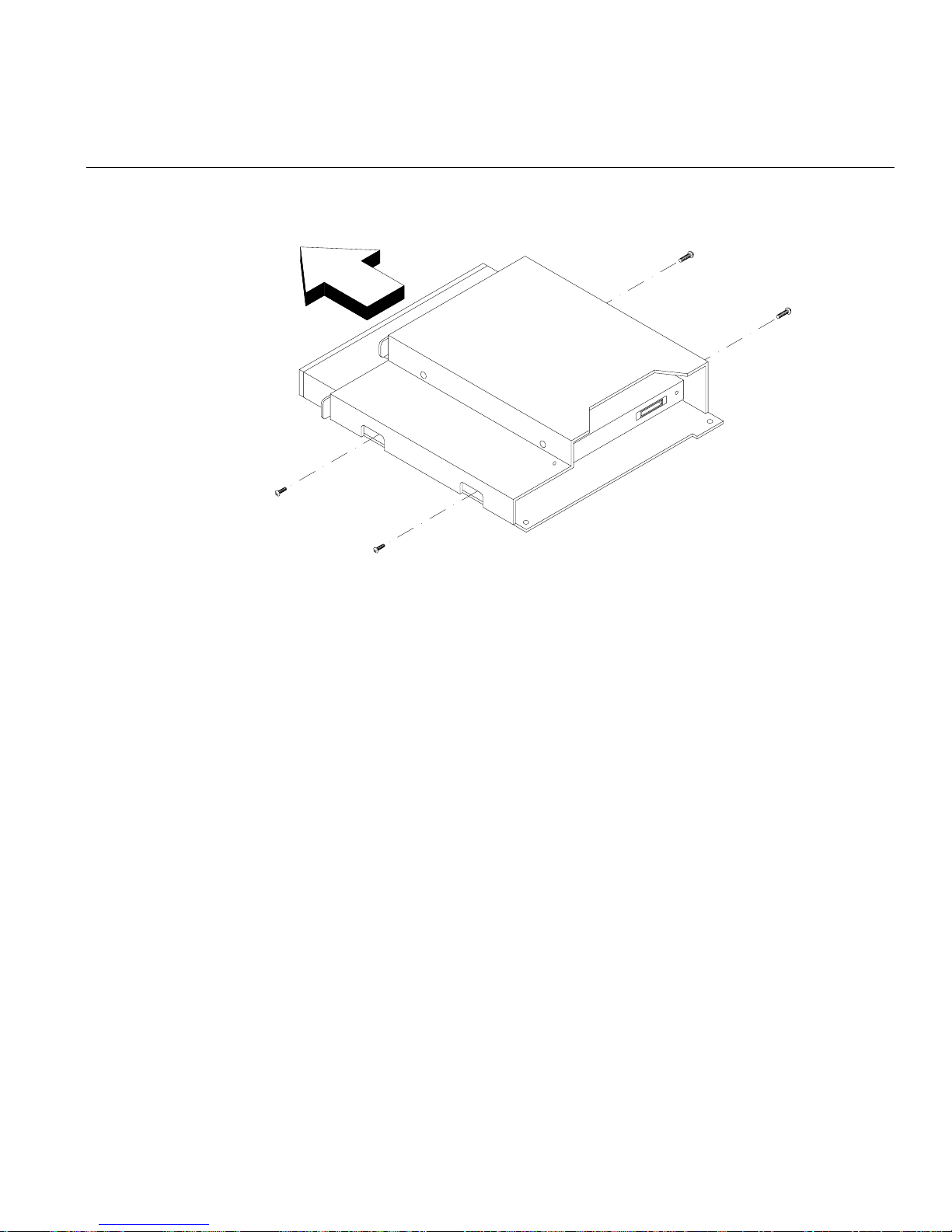
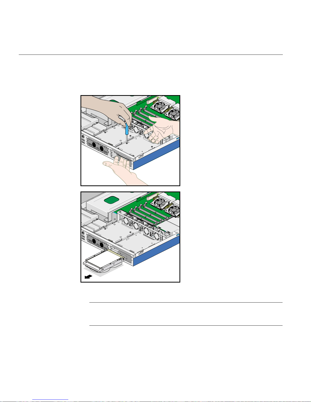
6. Remove two screws that hold the drive module to the chassis as shown in
Figure 2-28.
7. Gently slide the drive module back, and then lift it out of the chassis as shown in
Figure 2-28.
Figure 2-28 Removing the Drive Module
007-4047-001 53

2: Removing and Re placing System Components
Installing the Diskette Drive/CD-ROM Drive Module
Follow these steps to install the diskette drive/CD-ROM drive module:
1. Insert the drive module into its chassis.
2. Tighten the two screws to secure the drive module to the chassis as shown in
Figure 2-29.
3. Connect the CD-ROM drive signal cable to the CD-ROM drive connector as shown
in Figure 2-29.
Note: The CD-ROM drive signal cable is not a standard IDE cable. Instead, the
CD-ROM drive uses a signal cable with 50 conductors, some of which supply power.
4. Connect the diskette drive signal cable to the diskette drive connector. To do so,
follow these steps:
– Lift the connector retaining latch.
– Carefully insert the signal cable into the diskette drive connector.
– Push the retaining latch in on both sides of the connector, using a small
flat-head screwdriver. See Figure 2-29 for an illustration of the procedure.
Note: Follow the same procedure to connect the diskette drive signal cable to the
connector on the system board.
Note: The diskette drive signal cable is not a standard floppy drive cable. Instead,
the diskette drive uses a signal cable with 26 conductors, some of which supply
power.
54 007-4047-001

Replacing Removable-Media Devices
Raise retaining latch
Insert cable
Lower retaining latch
123
CD-ROM drive
data cable connector
Diskette drive
data cable
Figure 2-29 Connecting the Drive Module Signal Cables
5. Secure the signal cable retaining strap.
6. Install the link bar, as described in “Installing the Link Bar” on page 27.
7. Install the chassis cover as described in “Installing the Chassis Cover” on page 23.
007-4047-001 55

2: Removing and Re placing System Components
Replacing the Diskette Drive
Follow these steps to remove the diskette drive:
1. Remove the diskette drive module as described in “Removing the Diskette
Drive/CD-ROM Drive Module” on page 51.
2. Remove four screws, two on each side of the disk drive module, as shown in
Figure 2-30.
3. Gently pull the drive out of the dr ive module as shown in Figure 2-30.
Figure 2-30 Removing the Diskette Drive from the Drive Module
56 007-4047-001
Replacing Removable-Media Devices
Follow these steps to install the diskette drive:
1. Slide the diskette drive into the drive module as shown in Figure 2-31.
2. Tighten four screws, two on each side of the disk drive module, as shown in
Figure 2-31.
Figure 2-31 Installing the Diskette Drive into the Drive Module
3. Install the diskette drive module as described in “Installing the Diskette
Drive/CD-ROM Drive Module” on page 54.
007-4047-001 57
2: Removing and Re placing System Components
Replacing the CD-ROM Drive
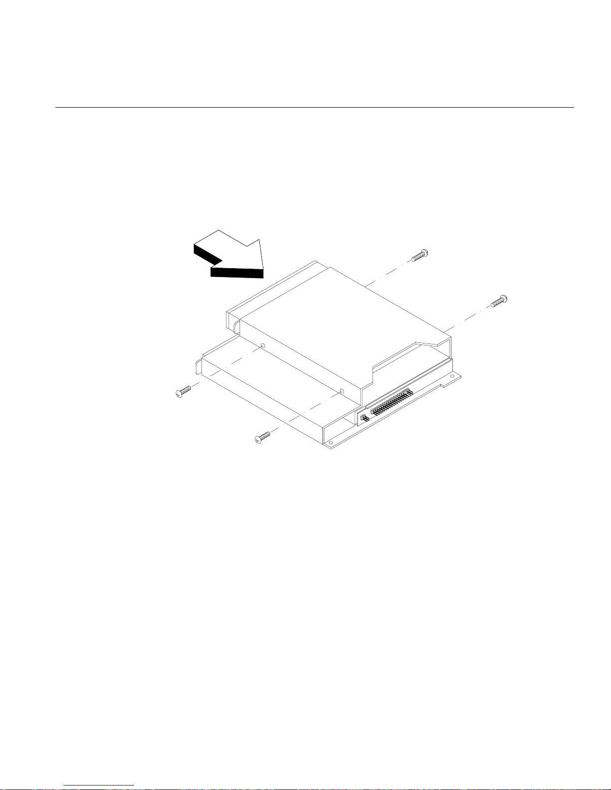
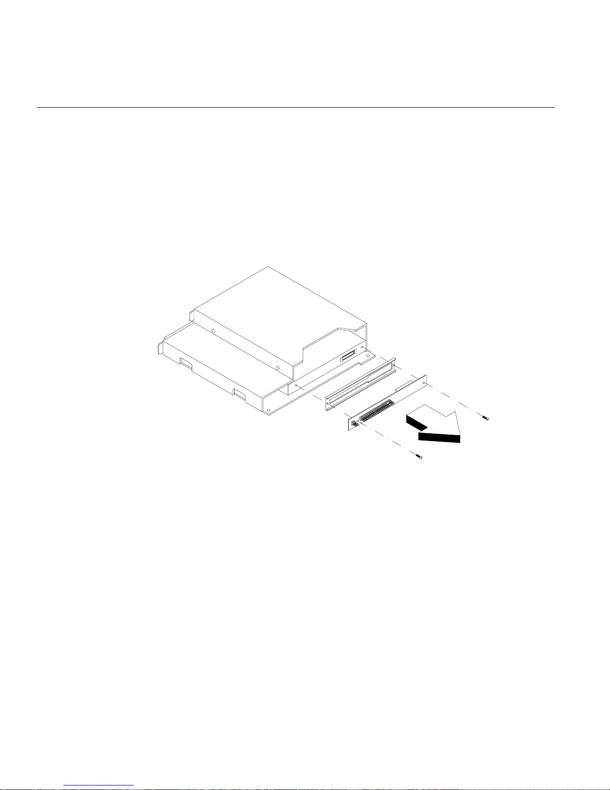
Follow these steps to remove the CD-ROM drive:
1. Remove the diskette drive module as described in “Removing the Diskette
Drive/CD-ROM Drive Module” on page 51.
2. Remove two screws to detach the IDE converter board and the plastic plate as
shown in Figure 2-32.
Figure 2-32 Removing the CD-ROM Drive Converter Board
3. Remove four screws, two on each side of the drive module, as shown in Figure 2-33.
4. Gently pull the drive out of the dr ive module as shown in Figure 2-33.
58 007-4047-001
Replacing Removable-Media Devices
Figure 2-33 Removing the CD-ROM Drive from the Drive Module
007-4047-001 59

2: Removing and Re placing System Components
Follow these steps to install the CD-ROM drive:
1. Remove the drive module from the chassis as described in “Removing the Diskette
Drive/CD-ROM Drive Module” on page 51.
2. Insert the CD-ROM drive into the drive module as shown in Figure 2-34.
3. Tighten the two screws located on the side of the drive module that is in contact
with the side of the chassis, as shown in Figure 2-34.
Figure 2-34 Installing the CD-ROM Drive into the Drive Module
60 007-4047-001
Replacing Removable-Media Devices
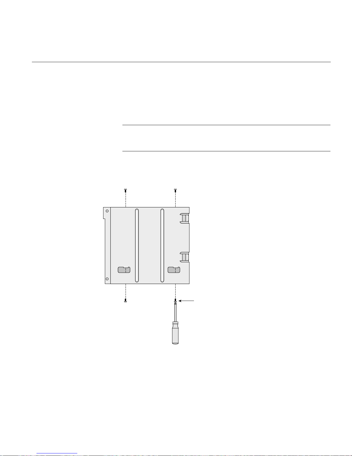
4. Follow these steps to tighten the two s crews on the oth e r side of the drive module:
– Hold the drive module vertically with the two empty screw holes poin ting
down as shown in Figure 2-35.
– Place a screw on the tip of a small Phillips screwdriver as s hown in Figure 2-35.
Note: If the type of Phillips screwdriver you are using does not allow a screw to
stay balanced on the tip of the screwdriver, see step 5 for an alternative
procedure.
– Pass the screw through the drive module opening and tigh ten the screw.
– Repeat this procedure for the other screw.
Figure 2-35 Securing the CD-ROM drive to the Drive Module
007-4047-001 61
Screw balanced
on tip of screwdriver

2: Removing and Re placing System Components
5. If the type of Phillips screwdriver you are using does not allow you to perform the
procedure shown in step 4, follow these alternative steps:
– Using needle-nose pliers, hold one of the screws through the hole in the drive
module.
– With your other hand, tighten the screw with a small Phillips screwdriver.
– Repeat this procedure for the other screw.
6. Install the diskette drive module as described in “Installing the Diskette
Drive/CD-ROM Drive Module” on page 54.
7. Install the chassis cover as described in “Installing the Chassis Cover” on page 23.
62 007-4047-001

Replacing a Hard Drive
This section covers the removal and installation of a hard drive.
Note: It is recommended that two people be available for some of the hard drive
replacement steps.
Removing a Hard Drive
Follow these steps to remove a hard drive:
1. Remove the chassis cover and the front panel as described in “Opening the Chassis”
on page 21.
2. Remove the EMI filler panel from in front of the hard drive by p ulling it straight
away from the chassis.
Replacing a Hard Drive
007-4047-001 63

2: Removing and Re placing System Components
3. Disconnect the power cable and the data cable from the back of the hard drive as
shown in Figure 2-36.
Data cables
Power
connectors
Figure 2-36 Removing Hard Drive Cables
64 007-4047-001

Replacing a Hard Drive
4. Remove two of the four screws that attach the hard drive to the chassis as shown in
Figure 2-37. The first two screws that you remove should be diagonally-l ocated.
5V
Figure 2-37 Removing Two of Four Hard Disk Drive Screws
007-4047-001 65
2: Removing and Re placing System Components
5. While another person hold s the hard drive in place, remove the remaining two
screws, as shown in Figure 2-38.
5V
5V
Figure 2-38 Removing the Hard Disk Drive
Note: If the drive is not held in place when the last 2 screws are r emoved, it will fall.
In order to avoid damage to the hard drive, and if there is no other person available
to help with this task, place a soft object under the drive to absorb the shock.
66 007-4047-001

Replacing a Hard Drive
6. Pull the drive out of the chassis.
7. Insert the EMI filler panel into the chassis if no other drive is to be installed.
Note: Ensure that the arrow on the EMI filler panel points up.
8. Install the chassis cover as described in “Installing the Chassis Cover” on page 23.
007-4047-001 67

2: Removing and Re placing System Components
Installing a Hard Disk Drive
Follow these steps to install a hard drive:
1. Remove the chassis cover and the front panel as described in “Opening the Chassis”
on page 21.
2. Remove the EMI filler panel by pulling it awa y f rom the chassis.
3. Ensure that the master/slave jumper on the hard drive is set correctly.
4. Place the hard drive (with the screw holes and connectors facing up) in the chassis.
5. While another person holds the hard drive up against the frame, tigh ten two
diagonally-located screws to secure the drive in place, as shown in Figure 2-39.
68 007-4047-001

Replacing a Hard Drive
5V
5V
Figure 2-39 Installing the Hard Disk Drive
Note: If there is no other person available to help with this task, place an object
under the hard drive to allow you to tighten the first two screws.
6. Tighten the remaining two screws.
7. Connect the power cable and the data cable to the back of the hard drive.
007-4047-001 69

2: Removing and Re placing System Components
8. Insert the EMI filler panel into the chassis.
Note: Ensure that the arrow on the EMI filler panel points up.
9. Install the chassis cover as described in “Installing the Chassis Cover” on page 23
and the front panel as described in “Removing and Installing the Front Pan e l” on
page 24.
70 007-4047-001

Replacing the Pow er Su pply Module
This section covers the removal and installation of th e power supply module:
Removing the Power Supply Module
Follow these steps to remove the power supply module:
1. Remove the chassis cover as described in “Removing the Chassis Cover” on
page 21.
2. Remove the intrusion alert microswitch module as described in “Replacing the
Intrusion Alert Microswitch Cable Module” on page 48.
3. Disconnect the power supply cable from the system board. See Figure 2-40 for the
location of the system board power supply connector.
Power supply
connector
Power
supply
Replacing the Power Supply Module
Figure 2-40 Location of the System Board Power Supply Connector
007-4047-001 71

2: Removing and Re placing System Components
4. Disconnect the power supply cable from the hard drives. See Figure 2-41 for the
location of the hard drive power supply connectors.
Power
connectors
Figure 2-41 Location of the Hard Drive Power Supply Connectors
72 007-4047-001

Replacing the Power Supply Module
5. Remove the metal air guide plate by releasing the two s c rews as shown in
Figure 2-42.
Air guide plate
Figure 2-42 Removing the Air Guide Plate
007-4047-001 73
2: Removing and Re placing System Components
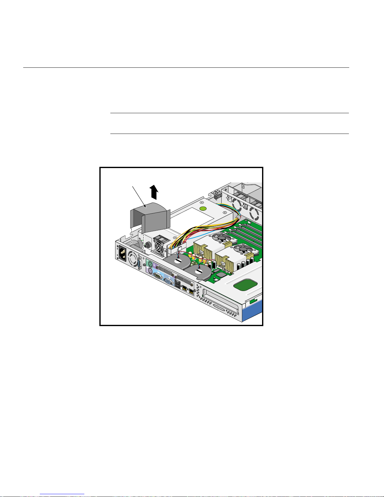
6. Remove the plastic plenum by separating it from the power supply module and
gently detaching it from the power socket module, as shown in Figure 2- 43.
Note: The plastic plenum adheres to the sides of the power socket module. Proceed
with care to free the plenum from the power socket module.
Plenum
Figure 2-43 Removing the Plastic Plenum
74 007-4047-001

Replacing the Power Supply Module
7. Remove the three screws from the power supply module as shown in Figure 2-44 .
Power supply
module
Power socket
assembly
Figure 2-44 Removing the Power Supply Module
007-4047-001 75

2: Removing and Re placing System Components
8. Remove three screws to release the power socket module as shown in Figure 2-44.
9. Lift up the power supply module from the chassis as shown in Figure 2-44.
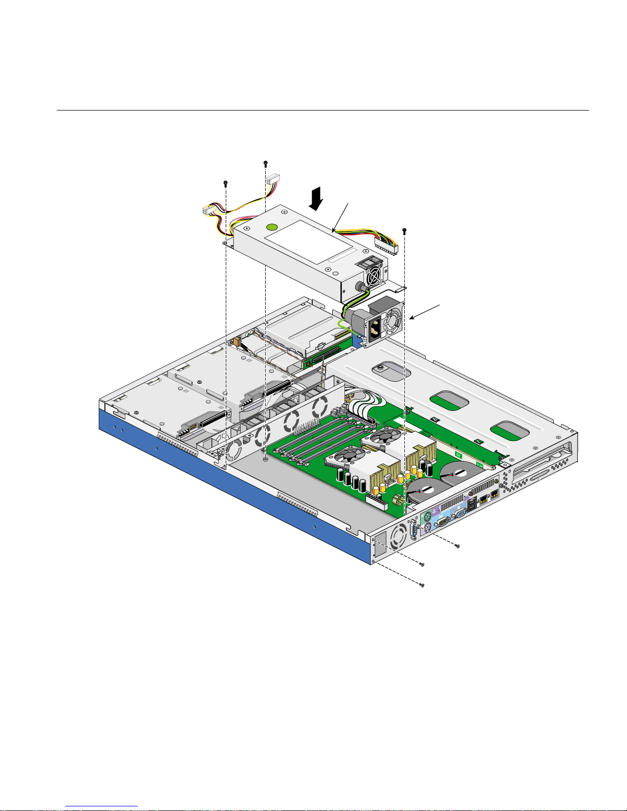
Installing the Power Supply Module
Follow these steps to install the powe r supply module:
1. Place the power supply module in the chassis as shown in Figure 2-45.
2. Tighten three screws to attach the power supply socket module to the rear panel as
shown in Figure 2-45.
76 007-4047-001
Power supply
module
Replacing the Power Supply Module
Power socket
assembly
Figure 2-45 Installing the Power Supply Module
007-4047-001 77
2: Removing and Re placing System Components
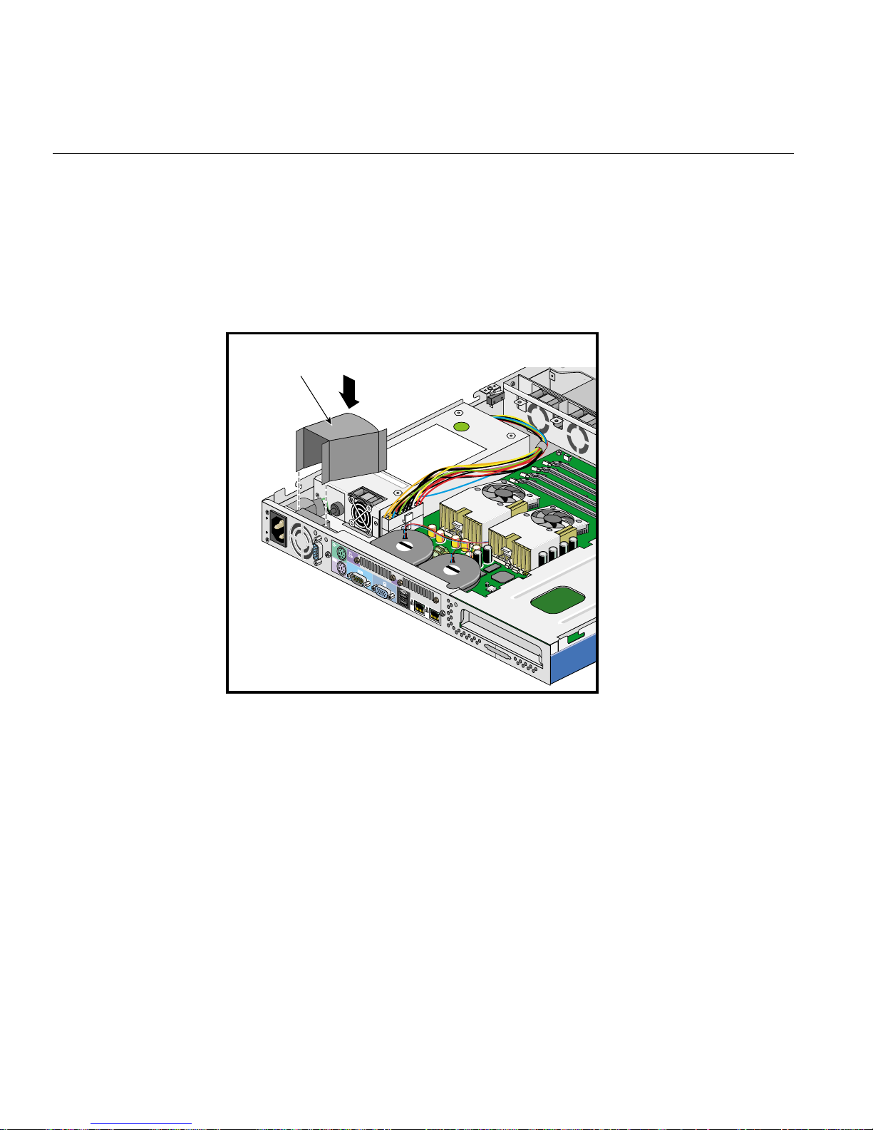
3. Follow these steps to install the plastic plenum:
– Align the narrow part of the plastic plenum with the air vent on the power
supply socket module, using the adhesive sides of the plenum to stick it into
position, as shown in Figure 2-46.
– Align the wide part of the plenum with the power supply fan opening.
Plenum
Figure 2-46 Installing the Plastic Plenum
4. Tighten three screws to secure the power supply module to the chassis as shown in
Figure 2-45.
78 007-4047-001
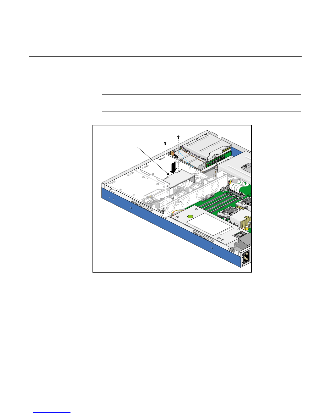
Replacing the Power Supply Module
5. Install the metal air guide plate and secure it with two screws as shown in
Figure 2-47.
Note: Ensure that all cables fit within the metal air guide plate opening, so that no
cables are stuck between the air guide plate and the chassis.
Air guide plate
Figure 2-47 Installing the Metal Air Guide Plate
007-4047-001 79

2: Removing and Re placing System Components
6. Connect the power supply cable to the system board. See Figure 2-40 on page 71 for
the location of the system board power supply connector.
7. Connect the power supply cable to the hard drives. See Figure 2-41 on page 72 for
the location of the hard drive power supply connectors.
8. Install the intrusion alert microswitch module as described in “Replacing the
Intrusion Alert Microswitch Cable Module” on page 48.
9. Install the chassis cover as described in “Installing the Chassis Cover” on page 23.
80 007-4047-001

Removing a Processor
Follow these steps to remove a processor:
1. Remove the chassis cover as described in “Removing the Chassis Cover” on
page 21.
2. Disconnect the fan/heatsink cables from the system board.
3. Follow these steps to remove the fan/heatsink assembly from the processor:
– Disconnect the fan/heatsink cable from the system board. See Figure 2-50 for
– Push on the releasing tab to unhook the metal bracket that is facing the rear of
– Lift the fan/heatsink assembly and unhook the other metal bracket. See step C
– Remove the fan/heatsink assembly from the processor.
Note: Avoid touching the thermal conductive grease on the bottom of the
fan/heatsink and the top of the processor.
Removing a Processor
the location of the cable connection.
the system. See steps A and B in Figure 2-48.
in Figure 2-48.
4. Pull up the socket lever (see step D in Figure 2-48). The processor pins will be
automatically released from the socket holes.
5. Lift the processor from the socket as shown in Figure2-48.
Caution: Do not touch the pins on the processor, so as to ensure long-term reliable
contact.
6. If you will now be using the system as a single-CPU system, this processor must be
replaced with a terminator board. See “Installing a Processor Terminator Board” on
page 86.
7. Install the chassis cover as described in “Installing the Chassis Cover” on page 23.
007-4047-001 81

2: Removing and Re placing System Components
A
B
C
D
Figure 2-48 Removing a Processor
82 007-4047-001

Installing a Processor
Follow these steps to install a processor:
Warning: B oth CPUs must be the same speed and cache size. Do not install CPUs
with different speeds or cache sizes; this would cause your system to malfunction.
1. Remove the chassis cover as described in “Removing the Chassis Cover” on
page 21.
2. Pull up the socket lever.
3. Remove the terminator board, if present.
4. Insert the processor, making sure that pin 1 (indicated by a triangle at the corner of
the processor) connects to hole 1 of the socket, as shown in Figure 2-49.
Caution: Do not touch the pins on the processor, so as to ensure long-term reliable
contact.
Installing a Processor
5. Pull down the socket lever to lock the processor into the socket. See step B in
Figure 2-49.
007-4047-001 83

2: Removing and Re placing System Components
C
A
B
Figure 2-49 Installing the Processor
E
D
F
6. Follow these procedures to attach the heatsink/fan assem b ly to the processor:
Note: Avoid touching the thermal conductive grease on the bottom of the
fan/heatsink and the top of the processor.
– Spread a small amount of thermal conductive grease on the top center of the
processor.
– Tilt the heatsink/fan assembly on the processor so as to be able to hook the
metal bracket that is facing the front of the chassis over the retaining hook on
the CPU socket. See step D in Figure 2-49.
– Place the heatsink/fan assembly flat on the processor.
– Push the releasing tab to latch the other metal bracket over the retaining hook
on the CPU socket. See steps E and F in Figure 2 -49 .
84 007-4047-001
 Loading...