

Page 1
User’s Manual
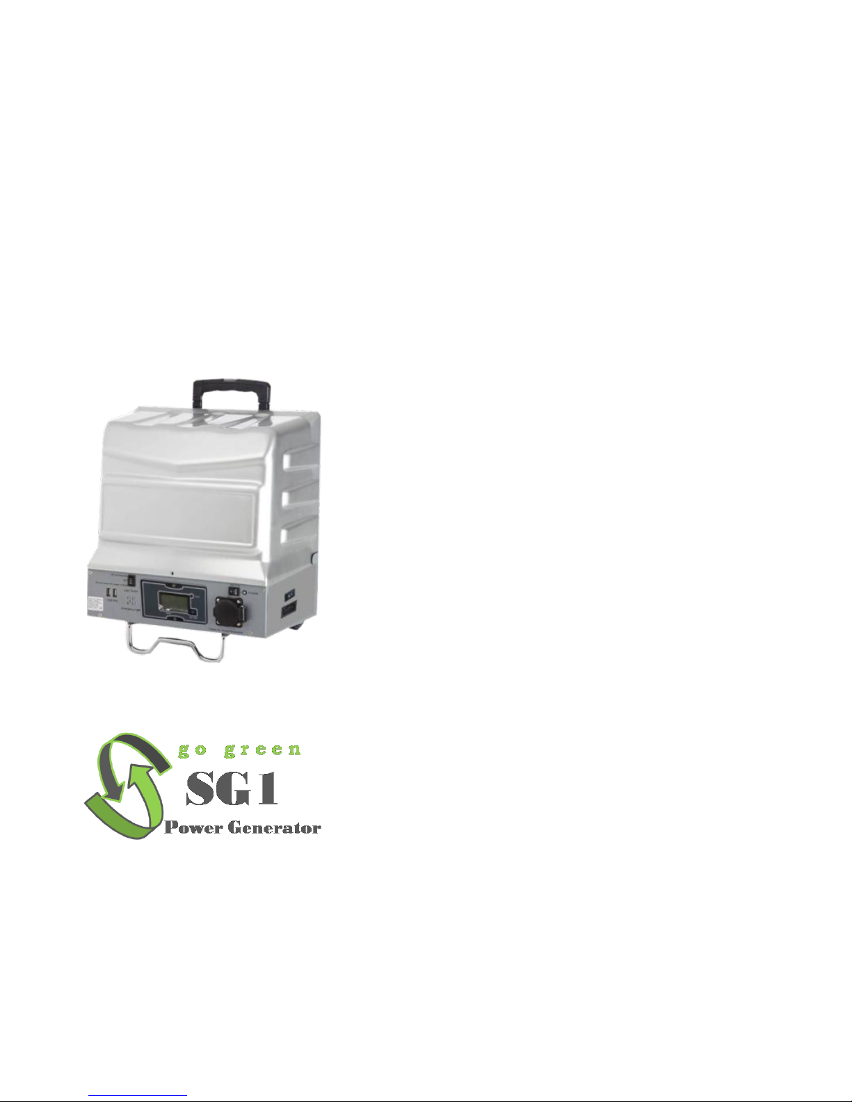
SG1 - Solar Generator (1000W)
Table of Contents 1
1. General Safety Precautions 2
1-1. General Safety Precautions 2
1-2. Precautions When Working with Batteries 2
2. Features 3-4
2-1. Working Condition & Application 3
2-2 Specification 4
3. Introduction Battery/Panel 4-5
3-1 Battery operation 4
3-2 Panel operation 5
3-3 Status LED 5
4. Electrical Performance 6-7
4-1 Specification SG1 6
4-2 Specification Solar Charger Controller 7
5. Introduction 8-10
5-1 Solar Generator SG1 8
5-2 Front view and side view 8-9
5-3 LED Indicator – Display function 10
6. Installation and Warning 11-13
6-1 Installation 11-12
6-2 Follow these guideline 12
6-3 Inverter Operation 13
6-4 Battery Installation and Replacement 13
7. Symbols Explanation/Recommend/Accessories 14-15
7-1 Equipment symbols explanation 14
7-2 Recommend Accessories 14-15
8. Trouble shooting 15
Page 2
1. Important Safety Instructions
WARNING!
Before using the Inverter, you need to read and save the
safety instructions.
When the photovoltaic array is exposed to light, it supplies
DC voltage to the PCE!
1-1. General Safety Precautions
1-1-1. Do not expose the Inverter to water, mist, snow, spray, or dust. To
reduce risk of hazard, do not cover or obstruct the ventilation shafts. Do
not install the Inverter in a zero-clearance compartment. Overheating may
occur.
1-1-2. To avoid a risk of fire and electronic shock, make sure that existing
wiring is in good electrical condition and not undersized. Do not operate
the Inverter with damaged or substandard Wiring.
1-1-3. There are some components in the inverter can cause arcs and
sparks. To prevent from fire or explosion, do not put batteries,flammable,
materials, or anything should be ignition–protected around the inverter.
1-2. Precautions When Working with Batteries
1-2-1. If battery acid contacts skin or clothing, you shall wash it out with
soap and water immediately. If battery acid contacts your eyes, you shall
wash it out with cold running water for at least 20 minutes and get medical
attention immediately.
1-2-2. Never smoke or make a spark or flame in the vicinity of the battery
or the engine.
1-2-3. Do not drop a metal tool on the battery. The resulting spark or short-
circuit on the battery of other electrical part may cause an explosion.
1-2-4. Remove personal metal items such as rings, bracelets, necklaces,
and watches when operating with a lead-acid batteries. Doing so may
cause short circuit and very high temperature, which can melt metal items
and even burn you.
2
2. Features
Modified sine wave output
Output frequency50 Hz
Input & output fully reinforce isolated design
High efficiency 75%
Driving highly reactive & capacitive loads at start moment
Color indicators show input voltage level
Loading controlled cooling fan
Advanced microprocessor
Protection: Input low voltage Overload Short circuit
Low battery voltage Input over voltage Over temperature
Overvoltage protection : 16.0V with LED Orange and long alarm
2-1. Working Condition & Application
2-1-1. Working Condition:
Working temp.: -10°C ~45°C
Storage temp.: -25°C ~70°C
Working humidity: 20%~90% RH non-condensing
Not for wet location use
Indoor use only, unconditional
Storage temp., Humidity: -30°C ~70°C/-22°F~+158°F,10~95% RH
Temp. Coefficient: ±0.05%°C(0~55°C)
Ingress protection rating:IP20
Pollution degree classification: class II
Maximum altitude rating: 2000M
Overvoltage category: II for PV input and AC output
The PV array should be earthed.
2-1-2. Application
Linear load :1000W and below
Inductive and capacitive load: 400W and below
The inverter output waveform is not sinusoidal .It can not be used for
Precision instruments !
Inductive load occurred a surger power at leat three times with its rate
power when it starts . Please note this principal when choose the
inverter !
Motor and impact drill etc. Load can not be used as the big power rush!
Recommend load : office equipment , Home entertainment electronics,
Lights ,etc.
3
Page 3
3 Introduction
3-1 Battery operation
Front view
A. ON/OFF switch: Leave in the OFF position during installation.
B . Over heat protection: LED sparkles when product temperature
gets high, it would shut down automatically while temperature arrives
55°C±5°C.
C.Overload protection: Orange LED lights when inverter/charger shut
down due to overloading. Inverter would re-start one time, if failed,
inverter would shut down. Please turn inverter OFF, reduce load and
turn inverter ON to reset.
D. AC socket: German
E. USB port : Max. Current 2A
F. Light switch : the light in front panel can supply lighting if needed
Side view:
A . Ventilation window: Do not obstruct, allow at least one inch for
airflow.
B. Fuse:40A/32V.If fuse damaged , please change it according to the
specification .
C. Solar port: MC4 Standard
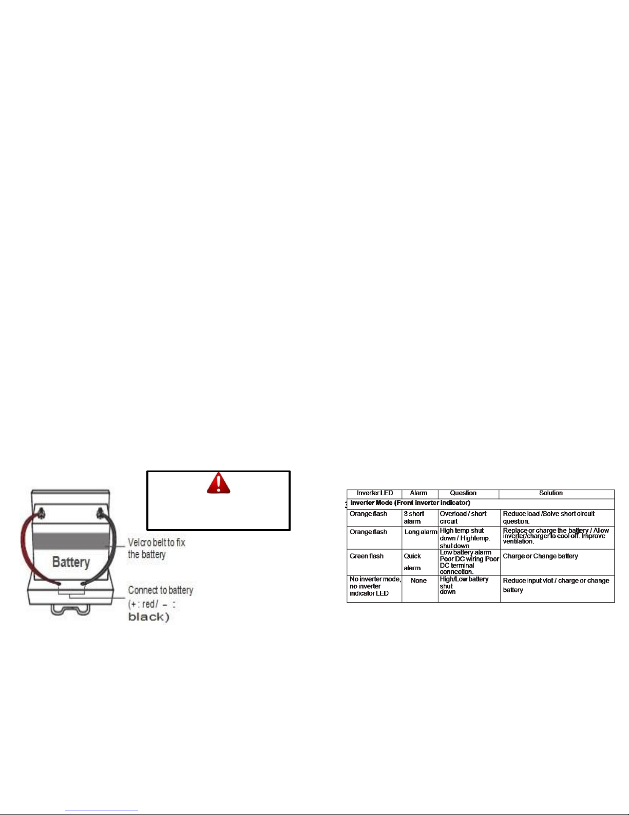
D. Battery terminals: Connect to 12V battery or other 12Vpower
source. "+“ is positive, "-" is negative.
Reverse polarity connection will blow internal fuse and may damage
inverter permanently.'Damage caused by reversed polarity is not
covered by the warranty.‘
4
WARNING!!
Operation of the inverter without a
proper ground connection may result
in an electrical safety hazard.
3-2 Panel operation
Front view
A. ON/OFF switch: Leave in the OFF position during installation.
B . Over heat protection: LED sparkles when product temperature
gets high, it would shut down automatically while temperature arrives
55°C±5°C.
C.Overload protection: Orange LED lights when inverter/charger shut
down due to overloading. Inverter would re-start one time, if failed,
inverter would shut down. Please turn inverter OFF, reduce load and
turn inverter ON to reset.
D. AC socket: German
E. USB port : Max. Current 2A
F. Light switch : the light in front panel can supply lighting if needed
Side view:
A . Ventilation window: Do not obstruct, allow at least one inch for
airflow.
B. Fuse:40A/32V.If fuse damaged , please change it according to the
specification .
C. Solar port: MC4 Standard
D. Battery terminals: Connect to 12V battery or other 12Vpower
source. "+"
is positive, "-" is negative.
Reverse polarity connection will blow internal fuse and may damage
inverter permanently.'Damage caused by reversed polarity is not
covered
by the warranty.‘
3-3 Status LED
5
Page 4
4. Electrical Performance
6
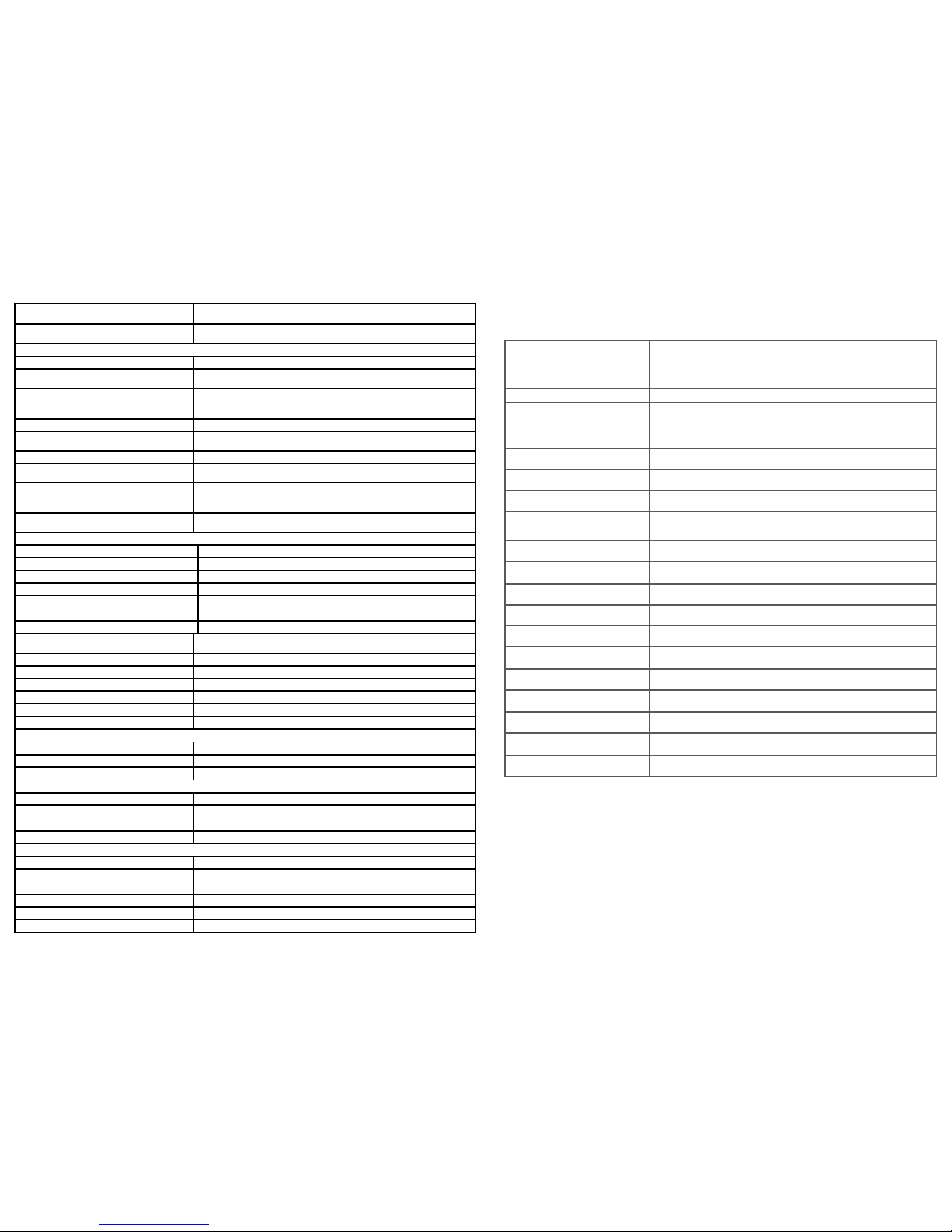
4-1 Specification SG1
Item
SG1
AC OUTPUT
Linear Load Power
1000Wa.c.
Inductive and capacitive load power
400W a.c.
AC Output Voltage
230V a.c +/- 3%
220 / 230 / 240V +/- 3%
AC Regulation
+/- 8% (100V:+/- 10% )
Frequency
50 Hz+/- 3%
Maximum continuous current
6.5A a.c.
Output Waveform
Modified Sine Wave
Efficiency
85,0%
No Load Current Draw
0.4A d.c. (12V )
PV input(Max. Rate power : 300W)
Vmax
22.7V d.c.
Voltage range:
18Vd.c.- 22.7Vd.c.
Maximum operating PV input current
20A d.c.
Isc PV
25A d.c.
Max. inverter backfeed current to the
array
None
DC INPUT
Rate voltage
12V d.c.
Voltage range
10-16V d.c.(12V)
Charge current(Max.)
20A d.c.
Bat. Low alarm
10.5+/-0.5V d.c.
Bat. Low Shutdown
10+/-0.5V d.c.
Over voltage
16+/-0.5V d.c.
Bat. Polarity Reverse
Fuse burn out
USB DC Port Output
Voltage
5V d.c.
Normal battery voltage
12V d.c.
Current
2A d.c.
SOLAR CHARGE CONTROLLER
Working voltage
12V d.c.
Rated charge current
20A d.c.
Over Bat. voltage protection
17V d.c.
Max .PV input voltage
22V d.c.
PROTECTION
Over load
Yes;Re-start 2 times, shutdown if failed
Maximum output over current
protection
6.8A a.c.
Over temp. protection
Yes;55℃+/-5℃
Inverter input reverse protection
Fuse blow
Inverter short circuit protection
Shut-off
Type
Solar Charger Controller
Rated charge current
20A
Rated load current
20A
Work voltage
12/24v AUTO
Over load, short circuit
protection
1.25 rated load current 60sec, 1.5 rated loads current 5sec, over load
protection action. ≥3 Rated load current short circuit protection action.
Self-consumption current
≤ 6mA
Charge circuit voltage drop
≤ 0.26V
Load circuit voltage drop
≤ 0.15V
Over voltage protection
17V(12V) /
34V(24V)
Work temperature
Industry stage: -35°C to +55°C; Commercial stage -5°C to +50°C
Boost charge voltage
14.6V(12V) / 29.2V(24V) ; (keep 10min) (only used when
overdischarging)
Direct charge voltage
14.4V(12V) / 28.8V(24V) ; (keep 10min)
Float charge voltage
13.6V(12V) / 27.2V(24V)
charge return voltage
13.2V(12V) / 26.4V(24V)
Temperature compensation
-5mv/°C/2v(Boost charger, Direct charger, Float charger, charger
return voltage);
Lower voltage indicate
12.0V(12V) / 24.0V(24V)
Over discharge voltage
11.1V(12V) / 22.2V(24V) ; (no load) - modified voltage by discharge
rate of battery
Over discharge return voltage
13.1V(12V) / 26.2V(24V)
Over-discharge pressed return
voltage
12.4V(12V) / 24.8V(24V)
Control mode
PWM charge mode; modified discharge voltage by the discharger rate
4-2 Specification Solar Charger Controller
NOTES: For use with solar panels only
Connector Installation.
IMPORTANT: Connect Battery FIRST
Wire size Max. current 4A /sq.mm.
Keep wiring lengths to a minimum to reduce voltage drop.
Connect battery wires to the controller first. Ensure correct polarity of terminals.
(Note. 1)
Connect the solar panel to the quick connector and expose to sunlight. The PV LED
will illuminate, indicating that the connection is correct and battery is charging.
7
Page 5

9
1 2 3
4 5
6 7 8 9
5 Introduction
5-1 Solar Generator SG1: Inverter/Charger with trolley and battery box:
1000W modified sine wave inverter with 20A solar charger controller
(option) + 100A lead acid battery (Recommended/ Option).
A Movable power system --- Modified sine wave inverter with multistage 10A
battery charger.
• Switch mode design.
• Compact and dexterous dimension design.
• Complete protection design --- overload, overtemp, short circuit, high/low
volt ...etc.
• Inverter re-start function.
• 3-stage charger design --- bulk, absorption, float.
• Wide volt range operation (90~135V, 180~265V)
• Durable and corrosion resistant construction. ( 9 ) Transformer isolated for
safety.
• Bypass function.
• Emergency backup light (LED) function.
• 20A PWM Solar charger controller function --- option.
• Max. 100Ah battery space.
• USB port. (5V /2A)
5-2 Front view and side view
8
10
11
DO NOT use this 2nd DC terminal alone.
Please connect the main battery cable inside the plastic
cover prior to 2nd terminal if you just have 1 battery.
Connection
Solar Panel
1 2
7
4 5
6
10
11
• DC Terminal: 20A
charging current max.
( for more
battery connection.)
• Solar Terminal (
ONLY with
solar charger
controller function.)
12. Charging with solar panel
12
on the back
Page 6
6. Installation and Warning
6-2 Installation : The power inverter should be installed in an environment
that meets the following requirements Dry – Do not allow water to drip on or
enter into the inverter.
Cool – Ambient air temperature should be between 0and 40, the cooler the
better.
Safe – Do not install the inverter in a battery compartment or other areas
where flammable fumes may exist, such as fuel storage areas or engine
compartments.
Ventilated –Keep the inverter a distance (as least 1 inch) away from
surrounding things.Ensure the ventilation shafts on the rear and the bottom of
the unit are not obstructed.
Dust – Do not install the Inverter in a dusty environments. The dust can be
inhaled into the unit when the cooling fan is working.
Close to batteries – Avoid excessive cable lengths.
Do not install the Inverter in the same compartment as batteries.
Use the recommended wire lengths and sizes(8AWG). Do not mount the
Inverter where it will be exposed to the gases produced by the battery. These
gases are very corrosive, and prolonged exposure will damage the Inverter.
WARNING!
Shock Hazard. Before proceeding further, carefully check that
the Inverter is NOT connected to any batteries, and that all wiring
is disconnected from any electrical sources. Do not connect the
output terminals of the Inverter to an incoming AC source.
CAUTION!!
This equipment is not ignition protected and employs components that tend
to produce
Arcs or sparks. To reduce the risk of fire or explosions, do not install in
compartments Containing batteries or flammable materials or areas in which
ignition protected equipment is required.
CAUTION!!
To reduce the risk of electric shock and prevent premature failure due to
corrosion,
do not mount where exposed to rain or spray.
CAUTION!!
To prevent fire, do not obstruct ventilation openings. Do not mount in a zero
clearance
compartment,overheating may result.
11
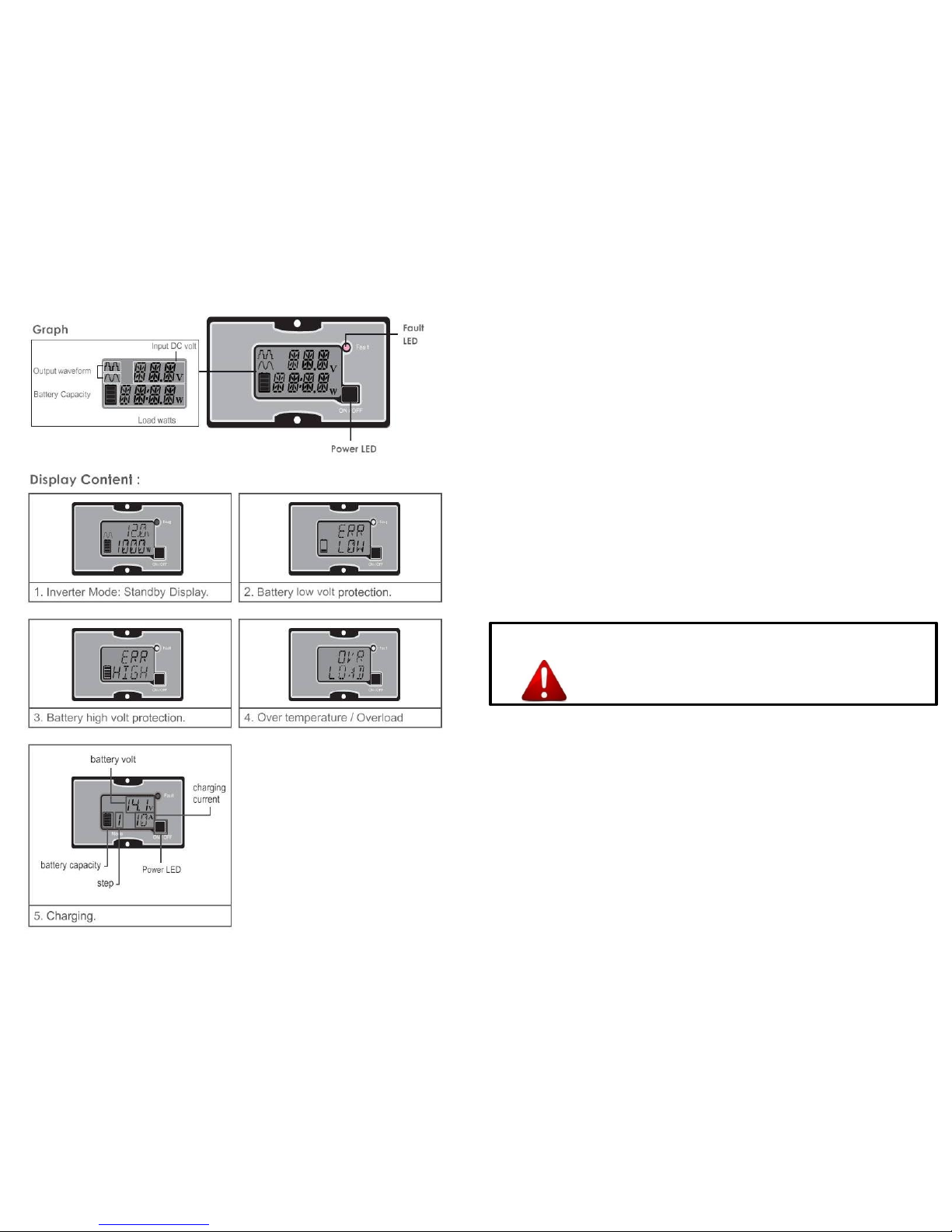
5-3 LED Indicator – Display function
10
Page 7
CAUTION!!
Risk of electrical shock. DC voltage source is existed inside this
equipment.Each circuit must be individually installed.
CAUTION!!
Risk of electrical shock. Do not remove cover, no user serviceable parts
inside. Refer servicing to qualified service personnel.
APPLICATION INFORMATION:
Provided with integral electronic protection against AC & DC overloads.
6-2: please follow these guideline to install the inverters :
A . Unpack and inspect the inverter,check to see that the power switch in the
OFF position.
B. Connect the cables to the power input terminals of inverter.
The red terminal is positive (+) and black terminal is negative (-). Connect
the cables into the terminals and tighten the wing nut to the wires securely.
C. Connect the cable from the negative terminal of the inverter to the
negative terminal of the power source. Make a secure connection.
CAUTION!!
Loosely tightened connectors result in excessive drop and may
cause overheated wires and melted insulation.
D. Before proceed further, carefully check if the terminals connect correctly.
CAUTION!!
Reverse polarity connection will blow a fuse in inverter and may
permanently damage the inverter. Damage caused by reverse
polarity connection is not covered by our warranty.
E. Connect the cable from the positive terminal of inverter to the positive terminal of
the power source. Make secure connection.
WARNING!!
You may observe a spark when you make this connection since
current may flow to charge capacitors in the power inverter.
Do not make this connection in the presence of flammable fumes,
explosions or fire may result.
F. Insert the MC4 connector of solar panel to the port .Make sure that the
polarity of PV array is right connected . G.Set power inverter switch to the
ON position and turn the test load on, the inverter should supply power to
the load.
12
6-3. Inverter Operation
To operate the power inverter, use the ON / OFF switch on the Front panel
to turn the power on. Then the power inverter is ready to deliver AC power
to your loads. If there is several loads use, turn them on separately after the
inverter is “ON” in order to prevent OVP resulted from the surge power.
6-3-1. Set the power switch to “ON” position .Then the inverter will make
self- diagnosis, and the LED’s indicators will turn to “Green” color, then the
inverter starts to work successfully.
6-3-2. Set the power switch to the OFF position, then the inverter stops and
all the lights go Off.
CAUTION!!
If the equipment is used in a manner not specified by the manufacturer, the
protection provided by the equipment may be impaired!
6-4 .Battery Installation and Replacement :
6-4-1 : Recommend battery:One piece 12V 100AH-130AH Lead-acid or
Gel battery with free maintenance.
6-4-2. When replacing batteries, replace with the same type and number of
batteries or battery packs with recommend. General instructions regarding
removal and installation of batteries;
CAUTION!!
Do not dispose of batteries in a fire. The batteries may explode;
CAUTION!!
Do not open or damage batteries. Released electrolyte is harmful to the skin and
eyes. It may be toxic;
CAUTION!!
A battery can present a risk of electrical shock and high short-circuit current.
6-4-3:The following precautions should be observed when working on
batteries:
A. Remove watches, rings, or other metal objects.
B. Use tools with insulated handles.
C. Wear rubber gloves and boots.
D. Do not lay tools or metal parts on top of batteries.
E. Disconnect charging source prior to connecting or disconnecting battery
terminals.
F. Determine if battery is inadvertently grounded. If inadvertently grounded,
remove source from ground. Contact with any part of a grounded
battery can result in electrical shock. The likelihood of such shock can
be reduced if such grounds are removed during installation and
maintenance (applicable to equipment and remote battery supplies not
having a grounded supply circuit).
13
Page 8
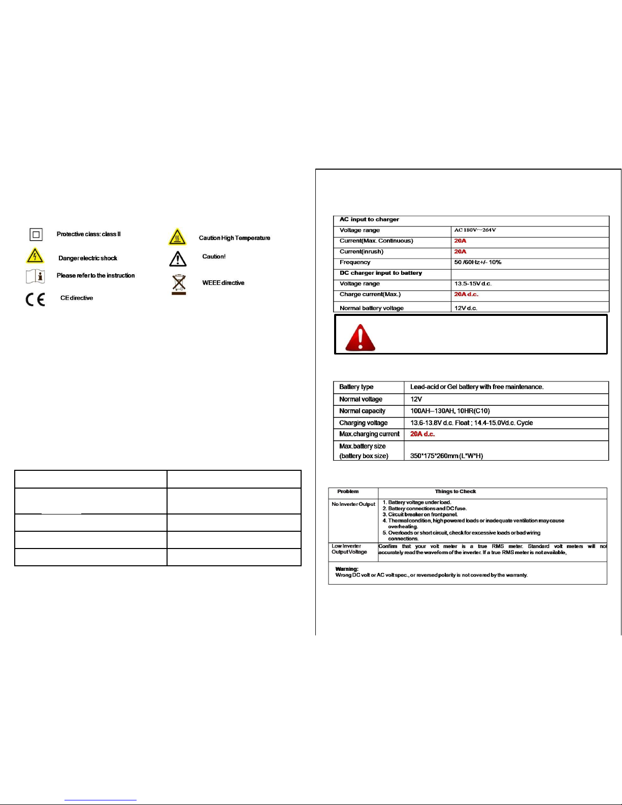
7-2-2 . DC charger electrical data
CAUTION!!
When DC charger is working ,please keep the inverter OFF!
When PV input is charging battery , please keep AC charger OFF!
7-2-3. Battery recommend :
8. Trouble shooting:
15
7. Symbols Explanation and Recommend Accessories
7-1. Equipment symbols explanation:
Products and batteries with the symbol(crossed-out wheeled bin)can not be
disposed as household waste .
Old electrical and electronic equipment and batteries should be recycled at
a facility capable of handing these items and their waste byproducts .
Contact your local authority for details in locating a recycle facility nearest
to you . Proper recycling and waste disposal will help conserve resources
whilst preventing detrimental effects on your health and the environment .
7-2. Recommend Accessories
7-2-1 . PV Solar panel electrical data
14
Max. Power (Pmax)
300W
PV input operating voltage
range(Effective charge)
18VDC- 22.7VDC
Max. Operating PV input current
27.5A
Isc (absolutely Max.)
20A
Max. Inverter back feed current to array
None
 Loading...