


SGI® Rackable™ C1110-RP6
System User Guide
007-5843-002

COPYRIGHT
© 2012, 2013 Silicon Graphics International Corp. All rights reserved; provided portions may be copyright in third parties, as indicated elsewhere herein. No
permission is granted to copy , distribute, or create derivative works from the contents of this electronic documentation in any manner, in whole or in part,
without the prior written permission of SGI.
LIMITED RIGHTS LEGEND
The electronic (software) version of this document was developed at private expense; if acquired under an agreement with the USA government or any
contractor thereto, it is acquired as "commercial computer software" subject to the provisions of its applicable license agreement, as specified in (a) 48 CFR
12.212 of the FAR; or, if acquired for Department of Defense units, (b) 48 CFR 227-7202 of the DoD FAR Supplement; or sections succeeding thereto.
Contractor/manufacturer is Silicon Graphics, International, Inc., 46600 Landing Parkway, Freemont, CA 94538.
TRADEMARKS AND ATTRIBUTIONS
Silicon Graphics, SGI, the SGI logo, Rackable, and Supportfolio are trademarks or registered trademarks of Silicon Graphics International Corp. or its
subsidiaries in the United States and other countries.
Intel, Intel QuickPath Interconnect (QPI) and Xeon are trademarks or registered trademarks of Intel Corporation or its subsidiaries in the United States and
other countries.
Infiniband is a trademark of the InfiniBand Trade Association.
Linux is a registered trademark of Linus Torvalds.
Novell is a registered trademark of Novell Inc., in the United States and other countries.
PCIe and PCI-X are registered trademarks of PCI SIG.
Red Hat and Red Hat Enterprise LINUX are registered trademarks of Red Hat Inc.
TYAN is a registered trademark of MiTAC International Corporation.
UNIX is a registered trademark in the United States and other countries, licensed exclusively through X/Open Company, Ltd.
All other trademarks mentioned herein are the property of their respective owners.

Record of Revision
Version Description
001 October 2012
Original publication
002 September 2013
Added support for Intel
miscellaneous front matter changes.
®
Xeon® E5-2600 and E5-2600v2 Series processors plus
:
007-5843-002 iii


Contents
Record of Revision . . . . . . . . . . . . . . . . . . . . . . . iii
About This Guide . . . . . . . . . . . . . . . . . . . . . . . ix
Audience. . . . . . . . . . . . . . . . . . . . . . . . . . ix
Related Publications. . . . . . . . . . . . . . . . . . . . . . . x
Product Support . . . . . . . . . . . . . . . . . . . . . . . . xi
Reader Comments . . . . . . . . . . . . . . . . . . . . . . . xi
1 Introduction and Overview . . . . . . . . . . . . . . . . . . . . 1
ESD and Safety Precautions. . . . . . . . . . . . . . . . . . . . . 1
System Overview . . . . . . . . . . . . . . . . . . . . . . . 2
Serverboard Features . . . . . . . . . . . . . . . . . . . . . 3
Processors . . . . . . . . . . . . . . . . . . . . . . . 3
Quick Path Interconnect (QPI). . . . . . . . . . . . . . . . . . 3
Memory . . . . . . . . . . . . . . . . . . . . . . . 4
Serial ATA/SAS . . . . . . . . . . . . . . . . . . . . . 4
PCI Expansion Slots . . . . . . . . . . . . . . . . . . . . 4
On-board Controllers/Ports . . . . . . . . . . . . . . . . . . 4
IPMI . . . . . . . . . . . . . . . . . . . . . . . . . 5
Other Features . . . . . . . . . . . . . . . . . . . . . . . 5
BMC Features . . . . . . . . . . . . . . . . . . . . . . . 5
PCIe Sub-system . . . . . . . . . . . . . . . . . . . . . . 6
Server Chassis Features . . . . . . . . . . . . . . . . . . . . . . 7
System Power . . . . . . . . . . . . . . . . . . . . . . . 7
Disk Drive Subsystem . . . . . . . . . . . . . . . . . . . . . 7
Control Panel . . . . . . . . . . . . . . . . . . . . . . . 8
Cooling System. . . . . . . . . . . . . . . . . . . . . . . 8
007-5843-002 v

Contents
2 System Operation . . . . . . . . . . . . . . . . . . . . . . . 9
Unpacking the System and Choosing an Operating Location . . . . . . . . . . . . 9
Preparing for Setup . . . . . . . . . . . . . . . . . . . . . . 9
Choosing a Setup Location . . . . . . . . . . . . . . . . . . . 9
Rack Precautions . . . . . . . . . . . . . . . . . . . . . . 10
Server Precautions . . . . . . . . . . . . . . . . . . . . . . 10
Rack Mounting Considerations . . . . . . . . . . . . . . . . . . . 11
Ambient Operating Temperature . . . . . . . . . . . . . . . . . 11
Reduced Airflow . . . . . . . . . . . . . . . . . . . . . 11
Mechanical Loading . . . . . . . . . . . . . . . . . . . . 11
Circuit Overloading. . . . . . . . . . . . . . . . . . . . . 11
Reliable Ground . . . . . . . . . . . . . . . . . . . . . 11
System Warnings and Precautions . . . . . . . . . . . . . . . . . . . 12
Installing the System into a Rack . . . . . . . . . . . . . . . . . . . 13
Identifying the Sections of the Rack Rails . . . . . . . . . . . . . . . . 13
Installing the Inner Rails . . . . . . . . . . . . . . . . . . . . 14
Installing the Outer Rails . . . . . . . . . . . . . . . . . . . . 14
Locking Tabs . . . . . . . . . . . . . . . . . . . . . . . 15
Installing the Server into the Rack . . . . . . . . . . . . . . . . . . 16
Installing the Server into a Telco Rack . . . . . . . . . . . . . . . . . 17
Server Access After Rack Installation . . . . . . . . . . . . . . . . . 17
Remove/Replace the Chassis Top Covers . . . . . . . . . . . . . . . 18
Checking the Components and Setup Before Power On . . . . . . . . . . . . 20
Checking the Hard Disk Drives . . . . . . . . . . . . . . . . . . . 20
Checking the Airflow . . . . . . . . . . . . . . . . . . . . . 20
Providing Power. . . . . . . . . . . . . . . . . . . . . . . 20
vi 007-5843-002

Contents
3 System Interfaces Overview . . . . . . . . . . . . . . . . . . . . 23
System Interface Overview . . . . . . . . . . . . . . . . . . . . . 23
Control Panel Buttons . . . . . . . . . . . . . . . . . . . . . 24
Control Panel LEDs . . . . . . . . . . . . . . . . . . . . . 24
HDD . . . . . . . . . . . . . . . . . . . . . . . . 25
Power . . . . . . . . . . . . . . . . . . . . . . . . 25
Universal Information LED . . . . . . . . . . . . . . . . . . 25
Disk Drive Carrier LEDs . . . . . . . . . . . . . . . . . . . . 25
4 Internal Component Replacement and Upgrades . . . . . . . . . . . . . . 27
General Precautions . . . . . . . . . . . . . . . . . . . . . . . 27
Installing System DIMM Memory . . . . . . . . . . . . . . . . . . . 27
Installing Memory DIMMs. . . . . . . . . . . . . . . . . . . . 29
Adding PCIe Cards . . . . . . . . . . . . . . . . . . . . . . . 30
System Fans. . . . . . . . . . . . . . . . . . . . . . . . 31
System Fan Failure. . . . . . . . . . . . . . . . . . . . . 31
Drive Bay Installation/Removal . . . . . . . . . . . . . . . . . . 31
Disk Drive Removal and Installation . . . . . . . . . . . . . . . . . . 31
Mounting a Drive in a Carrier . . . . . . . . . . . . . . . . . . . 32
Installing/Removing Hot-swap Drives . . . . . . . . . . . . . . . . . 32
Power Supply . . . . . . . . . . . . . . . . . . . . . . . . 34
Power Supply Failure . . . . . . . . . . . . . . . . . . . . . 35
Removing the 650-Watt Redundant Power Supply . . . . . . . . . . . . . 35
Installing a New 650-Watt Redundant Power Supply . . . . . . . . . . . . . 37
Removing the 450-Watt Non-Redundant Power Supply . . . . . . . . . . . . 38
Installing the 450-Watt Non-Redundant Power Supply . . . . . . . . . . . . 40
007-5843-002 vii

Contents
A System Specifications . . . . . . . . . . . . . . . . . . . . . . 41
Processors . . . . . . . . . . . . . . . . . . . . . . . . . 41
I/O Chipset . . . . . . . . . . . . . . . . . . . . . . . . . 41
BIOS . . . . . . . . . . . . . . . . . . . . . . . . . . . 41
Memory Capacity . . . . . . . . . . . . . . . . . . . . . . . 41
Disk Drive Controller . . . . . . . . . . . . . . . . . . . . . . 42
Drive Bays . . . . . . . . . . . . . . . . . . . . . . . . . 42
Expansion Slots . . . . . . . . . . . . . . . . . . . . . . . . 42
Serverboard . . . . . . . . . . . . . . . . . . . . . . . . . 42
Chassis . . . . . . . . . . . . . . . . . . . . . . . . . . 42
Weight . . . . . . . . . . . . . . . . . . . . . . . . . . 43
System Cooling . . . . . . . . . . . . . . . . . . . . . . . . 43
System Input Requirements . . . . . . . . . . . . . . . . . . . . . 43
Power Supply. . . . . . . . . . . . . . . . . . . . . . . . . 43
Environmental Specifications . . . . . . . . . . . . . . . . . . . . 44
Regulatory Compliance . . . . . . . . . . . . . . . . . . . . . . 45
viii 007-5843-002

Audience
. About This Guide
This guide provides an overview of the SGI® Rackable™ C1110-RP6 servers along with
instructions for system installation and general operation. The appendices include technical
specifications and safety practices.
This guide is written for owners, installers, system administrators, and users of C1110-RP6
servers. It is written with the assumption that the reader has a good working knowledge of
computers and computer systems.
007-5843-002 ix

About This Guide
Related Publications
Depending on your choice of system components and operating system, the following SGI
documents may be relevant to your server:
• SGI Foundation Software release notes
• SGI Performance Suite release notes
• SGI InfiniteStorage series documentation
• Man pages
You can obtain SGI documentation, release notes, or man pages in the following ways:
• Refer to the SGI Technical Publications Library at http://docs.sgi.com. Various formats are
• Refer to the SGI Supportfolio™ webpage for release notes and other documents whose
Note: For information on your motherboard and related system components, see the
documentation provided by the manufacturer/supplier.
available. This library contains the most recent set of books and man pages.
access require a support contract. See “Product Support” on page xi.
x 007-5843-002

Product Support
About This Guide
SGI provides a comprehensive product support and maintenance program for its products. SGI
also offers services to implement and integrate Linux applications in your environment.
• Refer to http://www.sgi.com/support/
• If you are in North America, contact the Technical Assistance Center at
+1 800 800 4SGI or contact your authorized service provider.
• If you are outside North America, contact the SGI subsidiary or authorized distributor in
your country.
Be sure to have the following information before you call Technical Support:
• Product serial number
• Product model name and number
• Applicable error messages
• Add-on boards or hardware
• Third-party hardware or software
• Operating system type and revision level
• Motherboard BIOS revision
Reader Comments
If you have comments about the technical accuracy, content, or organization of this document,
contact SGI. Be sure to include the title and document number of the manual with your comments.
(Online, the document number is located in the front matter of the manual. In printed manuals, the
document number is located at the bottom of each page.)
You can contact SGI in any of the following ways:
• Send e-mail to the following address: techpubs@sgi.com
• Contact your customer service representative and ask that an incident be filed in the SGI
incident tracking system:
http://www.sgi.com/support/supportcenters.html
SGI values your comments and will respond to them promptly.
007-5843-002 xi


Chapter 1
1. Introduction and Overview
This chapter provides an overview of your server’s main features.
Operating precautions are provided in this chapter, followed by a general overview of the product.
Before operating your system, familiarize yourself with the safety information that follow s:
ESD and Safety Precautions
Caution: Observe all ESD precautions. Failure to do so can result in damage to the equipment.
W ear an approved grounding wrist strap when you handle any ESD-sensitive device to eliminate
possible ESD damage to equipment. Connect the wrist strap cord directly to earth ground.
Warning: Before operating or servicing any part of this product, read the safety
precautions.
Danger: Keep fingers and conductive tools away from high-voltage areas. Failure to
follow these precautions will result in serious injury or death. The high-voltage areas of the
system are indicated with high-voltage warning labels.
Caution: Power off the system only after the system software has been shut down in an orderly
!
007-5843-002 1
manner. If you power off the system before you halt the operating system, data may be corrupted.

1: Introduction and Overview
System Overview
Warning: If a lithium battery is installed in your system as a soldered part, only qualified
SGI service personnel should replace this lithium battery. For a battery of another type,
replace it only with the same type or an equivalent type recommended by the battery
manufacturer, or an explosion could occur. Discard used batteries according to the
manufacturer’s instructions.
The SGI® Rackable™ C11 10-RP6 system is a compute-optimized server comprised of two main
subsystems: the 1U chassis and a serverboard (motherboard). Check with your sales or service
representative before loading any operating system on your server not provided by the SGI factory
or service organization.
Various hardware components may be included as part of your SGI Rackable C1110-RP6 system
configuration as listed below:
• Serverboard with:
–Two Intel
®
Xeon® E5-2600 or E5-2600v2 Series processors in LGA2011 sockets
– Intel C602 chipset and Quick Path Interconnect system bus support the processors
– Sixteen DDR3 memory DIMM slots
– T wo external Gen3 x16 PCIe slots (one full-height and one low-profile)
• Two disk drive configurations include:
– Four 3.5-inch hard disk drives plus DVD option drive
– Ten 2.5-inch hard disk drives (no DVD option available)
• Seven 4-cm counter-rotating cooling fans for the serverboard
• One 450 Watt auto-ranging power supply (with single power connector)
• Optional 650 Watt redundant auto-ranging power supply (with dual power connectors)
Note: The TYAN S7056 serverboard is the standard C1110-RP6 motherboard offering.
Other customized offerings may be available for specific system or clustering needs. Check
with your SGI sales or service representative for additional information.
2 007-5843-002

Serverboard Features
System Overview
Figure 1-1 Four-Drive C1110-RP6 System Chassis Front View Example
Figure 1-2 Ten-Drive C1110-RP6 System Chassis Front View Example
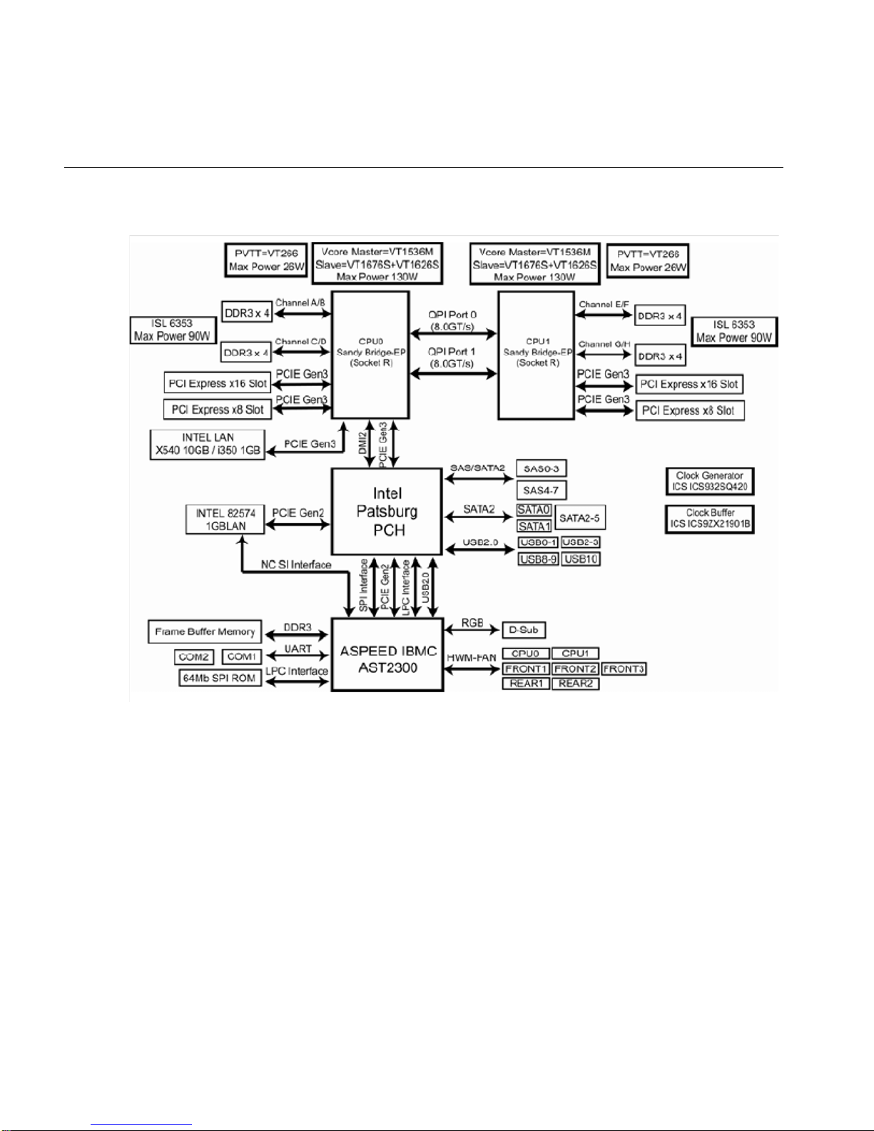
The SGI Rackable C1110-RP6 system has a dual processor serverboard based on the Intel C602
chipset. The following subsections describe the main features of the serverboard. See Figure 1-3
on page 6 for a functional block diagram of the serverboard.
Processors
Each serverboard supports two Intel Xeon series processors. Each processor sits in an LGA2011
socket and is interconnected via Intel QPI link support, see the next subsection for more
information on the QPI bus. Four-core, six-core and eight-core processors are available.
The exact type of processors provided with your system depends on the specific configuration you
ordered. Check with your SGI sales or service representative for information on processor
upgrades.
Quick Path Interconnect (QPI)
Separate QPI link pairs connect the two processors in an 8.0-GT/s network on the serverboard.
Each QPI comprises two 20-lane point-to-point data links, one in each direction (full duplex), with
a separate clock pair in each direction, for a total of 42 signals. Each signal is a differential pair,
so the total number of pins is 84. The 20 data lanes are divided onto four “quadrants” of 5 lanes
each. The basic unit of transfer is the 80-bit “flit”, which is transferred in two clock cycles (four
007-5843-002 3

1: Introduction and Overview
Memory
Serial ATA/SAS
20 bit transfers, two per clock.) The 80-bit “flit” has 8 bits for error detection, 8 bits for “link-layer
header” and 64 bits for “data”. QPI bandwidths are advertised by computing the transfer of 64 bits
(8 bytes) of data every two clock cycles in each direction
The SGI Rackable C1110-RP6 system has 16 DIMM slots that support registered ECC
DDR3-1600/1333/1066/800 SDRAM. Memory DIMMs of the same size and speed are highly
recommended for best overall system performance. A minimum of two DIMMs are required for
the server to be functional. For best memory performance, install DIMMs in multiples of eight.
See “Installing System DIMM Memory” in Chapter 4, for more details on installing memory.
A Serial ATA controller is integrated into the system serverboard to provide a SATA subsystem
with transfer rates up to 6 Gb/second. The optionally hot-swappable SATA drives are connected
to a backplane that provides power, bus termination and configuration settings. Optional SAS or
SAT A RAID 0, 1, 5, 6 and 10 are supported (RAID 5 and 6 require optional hardware). Note that
RAID functionality is required for hot-swap capability.
Note: Your operating system must support RAID functionality in order to use RAIDed drives.
The Intel C600 chipset provides BIOS-assisted software RAID only, not hardware RAID.
Hardware RAID support is available as an optional configuration.
Contact your SGI sales or service provider to order a specific RAID upgrade if your system was
not ordered with that option.
PCI Expansion Slots
The serverboard has two external PCI-Express Gen3 x16 slots.One slot is a low-profile form
factor, the other is a (half-length) full-height PCIe slot.
On-board Controllers/Ports
The rear-mounted I/O ports include one COM port, a VGA (monitor) port, two USB 2.0 ports, and
three Gigabit Ethernet ports (LAN3 is a shared IPMI port). A special serial port is included for
system management.
4 007-5843-002

IPMI
Other Features
BMC Features
System Overview
The IPMI (Intelligent Platform Management Interface) is a hardware-level interface specification
that provides remote access, monitoring and administration for the SGI Rackable C1110-RP6
system. IPMI allows server administrators to view a server’s hardware status remotely , receive an
alarm automatically if a failure occurs, and power cycle a system that is non-responsive.
Other on-board features that promote system health include voltage monitors, auto-switching
voltage regulators, chassis and CPU overheat sensors, virus protection and BIOS rescue.
The baseboard management controller (BMC) has the following features:
• The platform management subsystem uses the BMC to communicate with buses, sensors,
system BIOS, and server management firmware via the Server Management Bus (SMBUS)
• Enables serial-over-LAN (SOL) functionality via serial port B only
• Supports serial-console redirection in BIOS
• The BMC LAN may be configured in BIOS or via ipmitool.
• The ipmitool command is used to communicate with the BMC via an SOL session or by
using the web-based BMC interface.
007-5843-002 5
1: Introduction and Overview
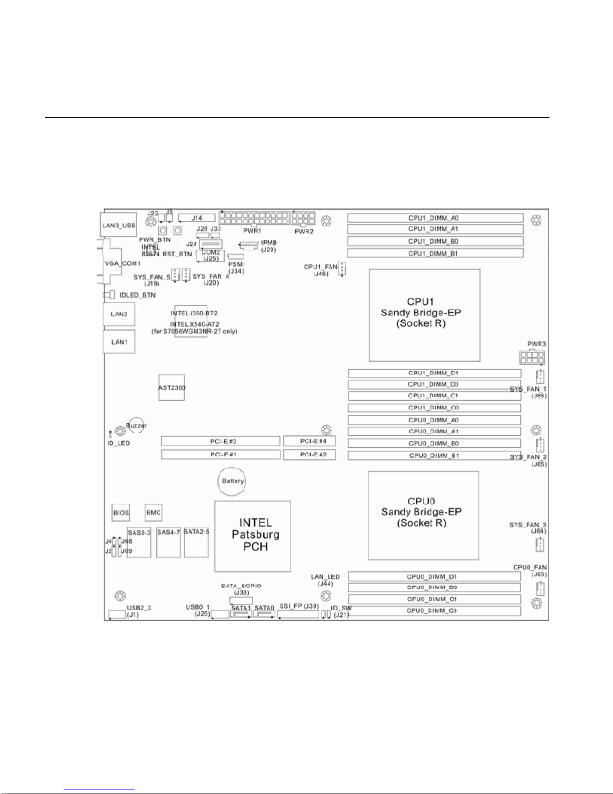
Figure 1-3 Functional Block Diagram of SGI Rackable C1110-RP6 System Server Board
PCIe Sub-system
The primary I/O bus for the serverboard is PCI Express.
6 007-5843-002
Server Chassis Features
The following sections provide a general outline of the main features of the 1U system chassis.
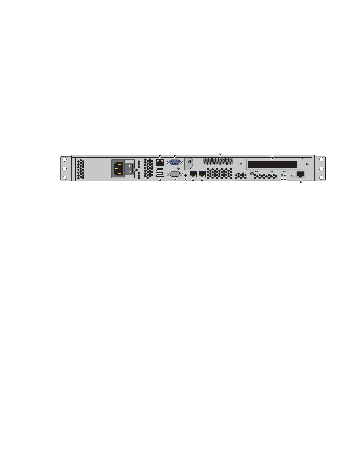
Figure 1-4 shows an example of the rear panel features of the SGI Rackable C1110-RP6 system.
VGA Port
IPMI
LAN/LAN3
Server Chassis Features
Low-profile x16 PCIe Slot
Full-height x16 PCIe slot
System Power
Disk Drive Subsystem
USB
Ports
COM
Figure 1-4 SGI Rackable C1110-RP6 System Rear Panel and I/O Ports
LAN2
LAN1
Port
UID LED
button
Power
Serial Port
HDD
activity
Your SGI Rackable C1110-RP6 system uses a single-cord high-efficiency 450-Watt cold-swap
power supply (shown on the left side of Figure 1-4). Optionally, a dual-cord 650-Watt redundant
power supply is available. Both types of supply are 80+ Gold rated.
The AC power supply cord(s) should always be removed from the system before servicing or
replacing the power supply.
The SGI Rackable C1110-RP6 system chassis includes four 3.5-inch drive bays or ten 2.5-inch
drive bays. These drives can be JBOD disks, or software RAID, or BIOS-assisted software RAID,
or optional hardware RAID disks. An optional SAS disk controller is also supported.
RAID support levels are as follows:
007-5843-002 7
1: Introduction and Overview
Control Panel
• Hardware RAID 0, 1, 10, 5 and 6 (with optional SAS HBA or Megaraid card)
• BIOS-assisted softwa re RAID 0, 1 and 10 when configured as a standalone server
• Linux software RAID 0 and 1 when configured as a compute node
Note: A cluster head node will only support hardware RAID options.
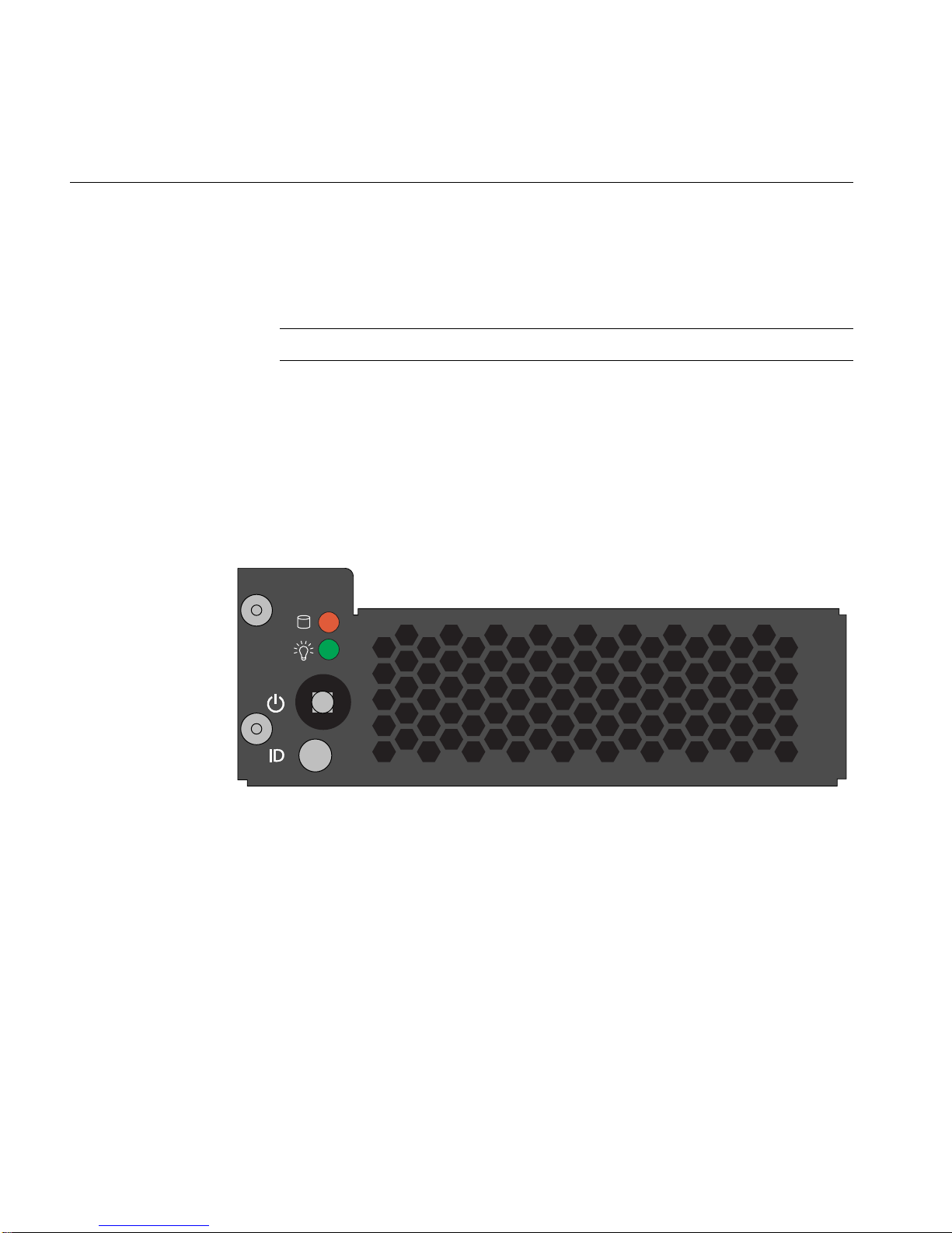
The SGI Rackable C1110-RP6 system control panel provides a system m onitoring and control
interface. The main power button included on the control panel will boot-up or shut down the
system when pressed - it does not remove all power inputs to the system. Remove the power
cord(s) from the system power supply if you need to remove power completely. LEDs on the
control panel (from top to bottom) indicate HDD activity, system power status and system UID.
Figure 1-5 SGI Rackable C110-RP6 Control Panel Example
Cooling System
The server chassis has an innovative cooling design that includes seven 4-cm counter-rotating
pulse width modulated (PWM) fans located in the middle section of the chassis. Additi onal
cooling fans are incorporated into each power supply module. All chassis and power supply fans
operate continuously while the system is on to efficiently cool the processors, memory and other
system components.
8 007-5843-002

Chapter 2
2. System Operation
This chapter describes the basic steps needed to get your SGI Rackable C1 110-RP6 system up and
running. Following these steps in the order given should enable you to have the system operational
within a minimum amount of time.
Unpacking the System and Choosing an Operating Location
You should inspect the box the system was shipped in and note if it was damaged in any way. If
the server itself shows damage you should file a damage claim with the carrier who delivered it.
When you decide on a suitable location for the rack unit that will hold the system, it should be
situated in a clean, dust-free area that is well ventilated. Avoid areas where heat, electrical noise
and electromagnetic fields are generated. You will also need it placed near a grounded power
outlet. Be sure to read the Rack and Server Precautions in the next section.
Preparing for Setup
The box the system was shipped in should include two sets of rail assemblies, two rail mounting
brackets and the mounting screws you will need to install the system into the rack. Follow the steps
in the order given to complete the installation process in a minimum amount of time. Please read
this section in its entirety before you begin the installation procedure outlined in the sections that
follow.
Choosing a Setup Location
Leave enough clearance in front of the rack to enable you to open the front door completely;
approximately 25 inches (63.5 cm) should be sufficient.
Leave approximately 30 inches (76.2 cm) of clearance in the back of the rack to allow for
sufficient airflow and ease in servicing.
007-5843-002 9

2: System Operation
Rack Precautions
This product is for installation only in a Restricted Access Location (dedicated equipment rooms,
service closets and the like).
This product is not suitable for use with visual display work place devices according to the
German Ordinance for Work with Visual Display Units.
The following guidelines help insure your rack systems proper operation:
• Ensure that the leveling jacks on the bottom of the rack are fully extended to the floor with
the full weight of the rack resting on them.
• In single rack installation, stabilizers should be attached to the rack.
• In multiple rack installations, the racks should be coupled together.
• Always make sure the rack is stable before extending a component from the rack.
• You should extend only one component at a time - extending two or more simultaneously
may cause the rack to become unstable.
• Always keep the rack's front door and all panels and components on the servers closed when
not servicing to maintain proper cooling.
Server Precautions
Review the electrical and general safety precautions in Chapter 1.
Determine the placement of each component in the rack before you install the rails.
Install the heaviest server components on the bottom of the rack first, and then work up.
For extra protection, use a regulating uninterruptible power supply (UPS) to protect the server
from power surges, voltage spikes and to keep your system operating in case of a power failure.
This is an optional device not provided by SGI with your system.
Allow the hot plug disk drives and power supply modules to cool before touching them. Always
keep the server closed when not servicing to maintain proper cooling.
Make sure all power and data cables are properly connected and not blocking the chassis airflow.
10 007-5843-002

Rack Mounting Considerations
Use the guidelines in the following subsections to properly install, use and maintain a server in a
rack.
Ambient Operating Temperature
If installed in a closed or multi-unit rack assembly, the ambient operating temperature of the rack
environment may be greater than the ambient temperature of the room. Therefore, consideration
should be given to installing the equipment in an environment compatible with the manufacturer’s
maximum rated ambient temperature (Tmra).
Reduced Airflow
Equipment should be mounted into a rack so that the amount of airflow required for safe operation
is not compromised.
Mechanical Loading
Equipment should be mounted into a rack so that a hazardous condition does not arise due to
uneven mechanical loading.
Unpacking the System and Choosing an Operating Location
Circuit Overloading
Consideration should be given to the connection of the equipment to the power supply circuitry
and the effect that any possible overloading of circuits might have on over-current protection and
power supply wiring. Appropriate consideration of equipment nameplate ratings should be used
when addressing this concern.
Reliable Ground
A reliable ground must be maintained at all times. To ensure this, the rack itself should be
grounded. Particular attention should be given to power supply connections other than the direct
connections to the branch circuit (i.e. the use of power strips, etc.).
007-5843-002 11
2: System Operation
System Warnings and Precautions
!
!
!
!
!
Warning: The SGI Rackable C1110-RP6 server weighs up to ~30 lbs (~13.6 kg). Always
use proper lifting techniques when you move the server. Always get the assistance of another
qualified person when you install the sever in a location above your shoulders. Failure to do
so may result in serious personal injury or damage to the equipment.
Warning: Extend the leveling jacks on the bottom of the rack to the floor with the full
weight of the rack resting on them. Failure to do so can result in serious injury or death.
Warning: Attach stabilizers to the rack in single rack installations. Failure to do so can
result in serious injury or death. Couple racks together in multiple rack installations.
Failure to do so can result in serious injury or death.
Warning: Be s ure the rack is stable befor e extending a component fr om the rack. Failur e
to do so can result in serious injury or death.
Warning: Extend only one rack component at a time. Extending tw o or more component s
simultaneously may cause the rack to tip over and result in serious injury or death.
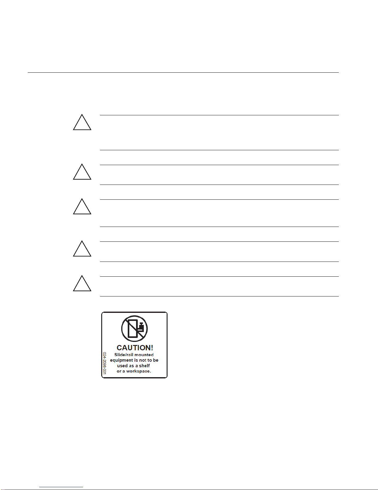
Slide/Rail Equipment Usage Caution
12 007-5843-002
Installing the System into a Rack
This section provides information on installing the SGI Rackable C1110-RP6 system into a rack
unit with the rack rails provided. If the system has already been mounted into a rack, you can skip
ahead to the next section. There are a variety of rack units on the market, which may mean the
assembly procedure will differ slightly. You should also refer to the installation instructions that
came with the rack unit you are using.
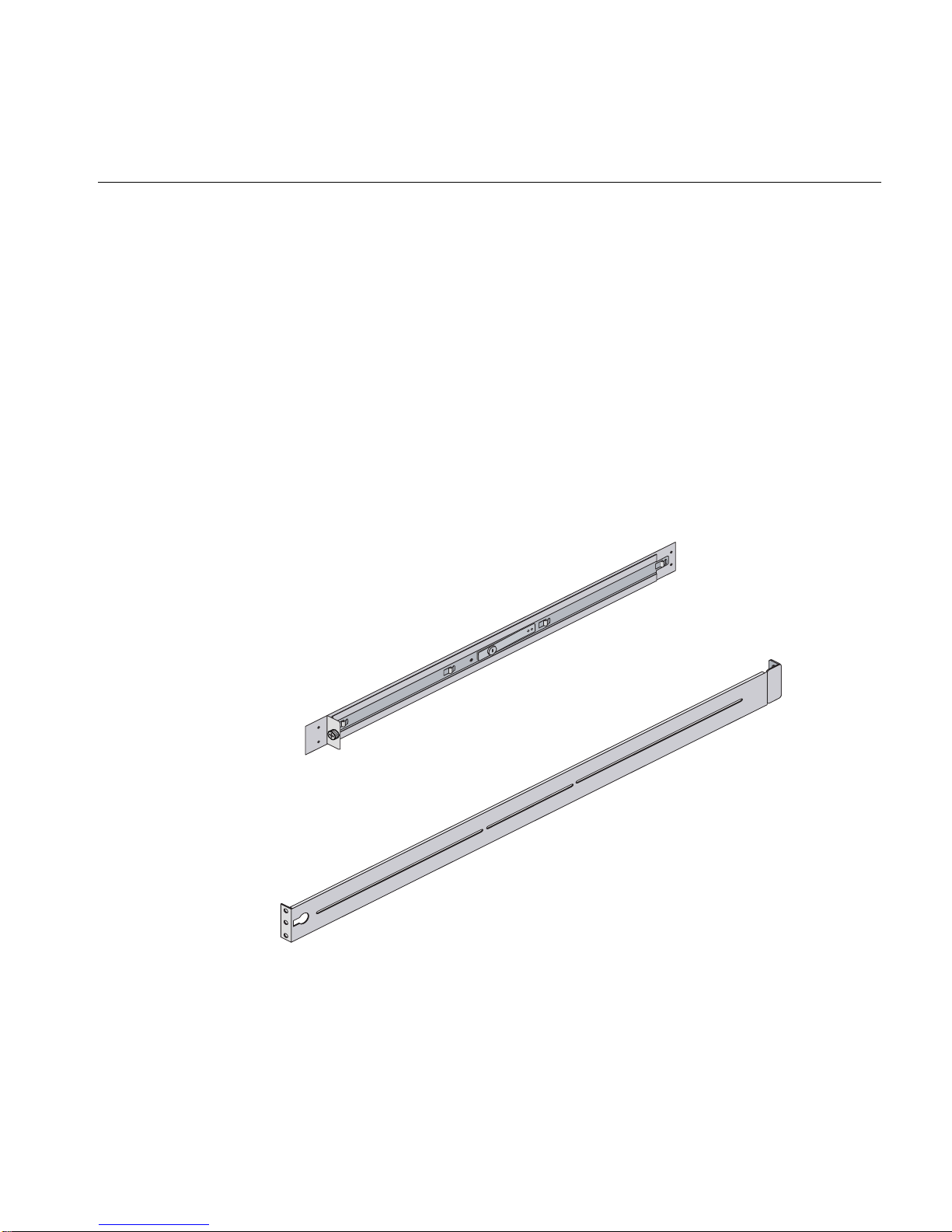
Identifying the Sections of the Rack Rails
You should have received two rack rail assemblies in the rack mounting kit. Each assembly
consists of two sections: an inner fixed chassis rail that secures directly to the server chassis and
an outer fixed rack rail that secures directly to the rack itself (see Figure 2-1). Two pairs of short
brackets to be used on the front side of the outer rails are also included.
Installing the System into a Rack
Figure 2-1 SGI Rackable C1110-RP6 System Rack Rails Example
007-5843-002 13

2: System Operation
Installing the Inner Rails
Both the left and right side inner rails should have been pre-attached to the chassis as shown in the
example in Figure 2-2. Proceed to the next subsection for information on installing the outer rails
into a rack.
Figure 2-2 Chassis Attachment to Inner Rack Rails Example
Installing the Outer Rails
Begin by measuring the distance from the front rail to the rear rail of the rack. Attach a short
bracket to the front side of the right outer rail and a long bracket to the rear side of the right outer
rail. Adjust both the short and long brackets to the proper distance so that the rail can fit snugly
into the rack.
Secure the short bracket to the front side of the outer rail with two M4 screws and the long bracket
to the rear side of the outer rail with three M4 screws. Repeat these steps for the left outer rail, see
Figure 2-3 on page 15 for an example.
14 007-5843-002

Installing the System into a Rack
Figure 2-3 Outer Rail Attachment to Rack Example
Locking Tabs
Both chassis rails have a locking tab, which serves two functions. The first is to lock the server
into place when installed and pushed fully into the rack, which is its normal position. Secondly,
these tabs also lock the server in place when fully extended from the rack. This prevents the server
from coming completely out of the rack when you pull it out for servicing.
007-5843-002 15

2: System Operation
Installing the Server into the Rac k
Y ou should now have rails attached to both the chassis and the rack unit. The next step is to install
the server into the rack. Do this by lining up the rear of the chassis rails with the front of the rack
rails. Slide the chassis rails into the rack rails, keeping the pressure even on both sides (you may
have to depress the locking tabs when inserting the unit). See Figure 2-4 for an example. When
the server has been pushed completely into the rack, you should hear the locking tabs "click" into
place.
Figure 2-4 Sliding the System into a Rack
16 007-5843-002

Installing the Server into a Telco Rack
T o install the server into a T elc o type rack, use two L-shaped brackets on either side of the chassis
(four total). First, determine how far the server will extend out the front of the rack. Larger chassis
should be positioned to balance the weight between front and back. If a bezel is included on your
server, remove it. Then attach the two front brackets to each side of the chassis, then the two rear
brackets positioned with just enough space to accommodate the width of the rack. Finish by
sliding the chassis into the rack and tightening the brackets to the rack.
Server Access After Rack Installation
After you install the unit in the rack, you may need to open the top cover (see Figure 2-5 on
page 18) to access the serverboard or confirm that all components are properly installed and all
the connections have been made.
Grasp the two handles on either side and pull the system straight out until it locks (you should hear
a "click"). If you need to remove the server completely: disconnect all cables at the rear, depress
the locking rail-tabs on either side of the server and slide it completely off the outer rack rail
assembly. The server is heavy when fully loaded, use two people for this process if possible.
Installing the System into a Rack
007-5843-002 17

2: System Operation
Figure 2-5 Top View of Server
Remove/Replace the Chassis Top Covers
Use the following information to remove the chassis top cover over the serverboard:
1. Using a Phillips-head screwdriver, remove the two screws that secure the motherboard top
covers to the chassis.
2. Place your thumbs in the top-cover recess “button” and push the rear section of the top cover
away from you (toward the rear of the chassis) and lift it upward, see Figure 2-6 on page 19.
3. Lift the top cover from the chassis to gain full access to the serverboard, DIMMs, fans,
power supply and PCIe cards.
4. Reverse the process to reinstall the rear top cover section.
18 007-5843-002

Installing the System into a Rack
Figure 2-6 Server T op Covers Removal Example
Use the following steps to remove the (front) chassis top cover over the system drives:
1. Use your thumbs in the top-cover recess “button” to push the front section of the top cover
towards the front of the system and lift upward.
2. Lift the front cover section up and away from the server chassis to access the drive assembly
and backplane interconnects.
3. Reverse the process steps to reinstall the front section of the chassis top cover.
Important: Always replace both top covers when operating the server to ensure thermal
stability.
007-5843-002 19

2: System Operation
Checking the Components and Setup Before Power On
If any internal modifications have been made to the server prior to installation in the rack, you may
wish to recheck the server’s interior.
You should have two processors already installed on the serverboard. Each processor needs its
own heatsink.
Your server comes with system memory already installed. Make sure all DIMMs are fully seated
in their slots. For details on adding system memory, see “Installing System DIMM Memory” on
page 27.
Make sure all power and data cables are properly connected and not blocking the chassis airflow.
Checking the Hard Disk Drives
The system disk drives are accessible from the front of the server and can be installed and removed
from the front of the chassis without removing the top chassis cover.
Depending upon your system's configuration, your system will have one or more drives already
installed.
Checking the Airflow
Airflow through the server is provided by an air shroud and seven 4-cm counter-rotating cooling
fans for the node board and other internal components of the chassis. The system component
layout was carefully designed to direct sufficient cooling airflow to the components that generate
the most heat. Each power supply has it’s own built-in cooling fan assembly.
Note that all power and data cables should be routed in such a way that they do not block the
airflow generated by the fans.
Providing Power
Plug the power cord(s) from the server power supply unit into a rack power distribution unit
(PDU) or high-quality power strip that offers protection from electrical noise and power surges.
20 007-5843-002
Installing the System into a Rack
For higher availability it is recommended that you use an optional uninterruptible power supply
(UPS) with the server.
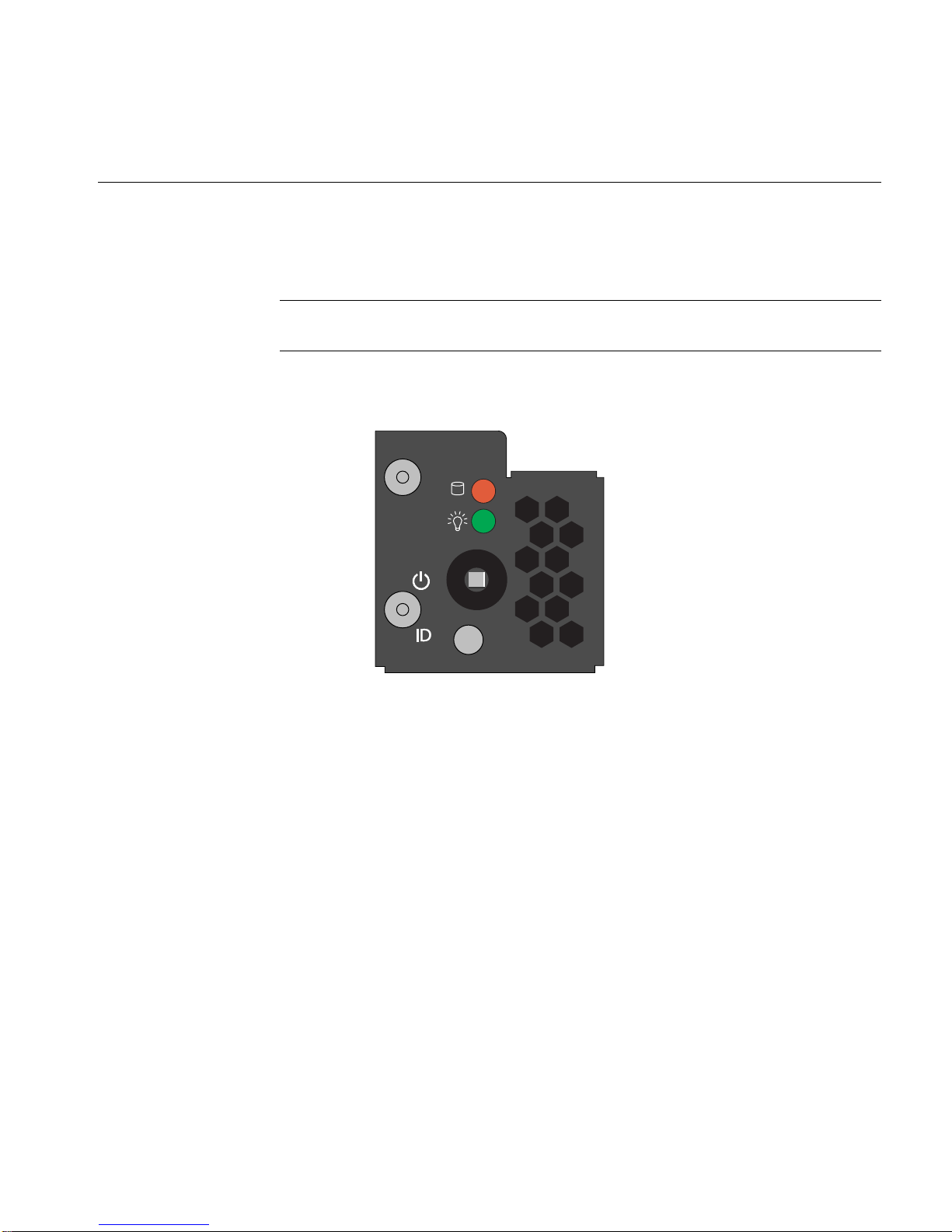
Note: The blue LED indicates unit identification (UID) when activated by an IPMI tool command
or using the button on the rear of the chassis.
See Chapter 3 for a complete overview of the front control panel LED and button functions.
Figure 2-7 Server Front Control Panel Example
007-5843-002 21

Chapter 3
3. System Interfaces Overview
This chapter provides an overview of the standard and optional interfaces available on your SGI
Rackable C11 10-RP6 system. The major components of the system are described and illustrated.
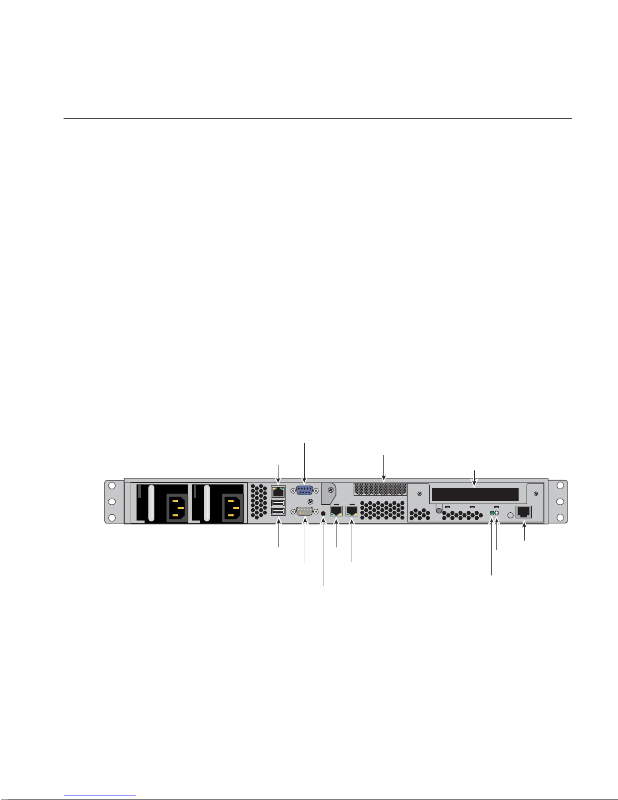
System Interface Overview
Figure 3-1 shows an example of the system rear interconnects. Each system can be configured
slightly differently in regards to PCIe options, drives and power supplies. Note that the example
shown uses the 650-Watt redundant power supply.
System Interface Overview
VGA Port
IPMI
LAN/LAN3
USB
Ports
COM
Port
UID LED
Low-profile x16 PCIe Slot
LAN2
LAN1
button
Full-height x16 PCIe slot
Serial Port
HDD
activity
Power
Figure 3-1 Server Rear Connectors Example
007-5843-002 23
3: System Interfaces Overview
Control Panel Buttons
Control Panel LEDs
There are several LEDs on the front control panel as well as others on the disk drive carriers to
keep you constantly informed of the overall status of the system as well as the activity and health
of specific components. There is also a system power button on each control panel. This chapter
explains the meanings of all LED indicators and the appropriate response you may need to take.
There is only one push-button located on the front control panel of the C1110-RP6 server:
Power - This is the main power button, which is used to apply or turn off the main system power
supply. Pressing this button removes the main power but keeps standby power supplied to the
serverboard, see Figure 3 -2 on page 24.
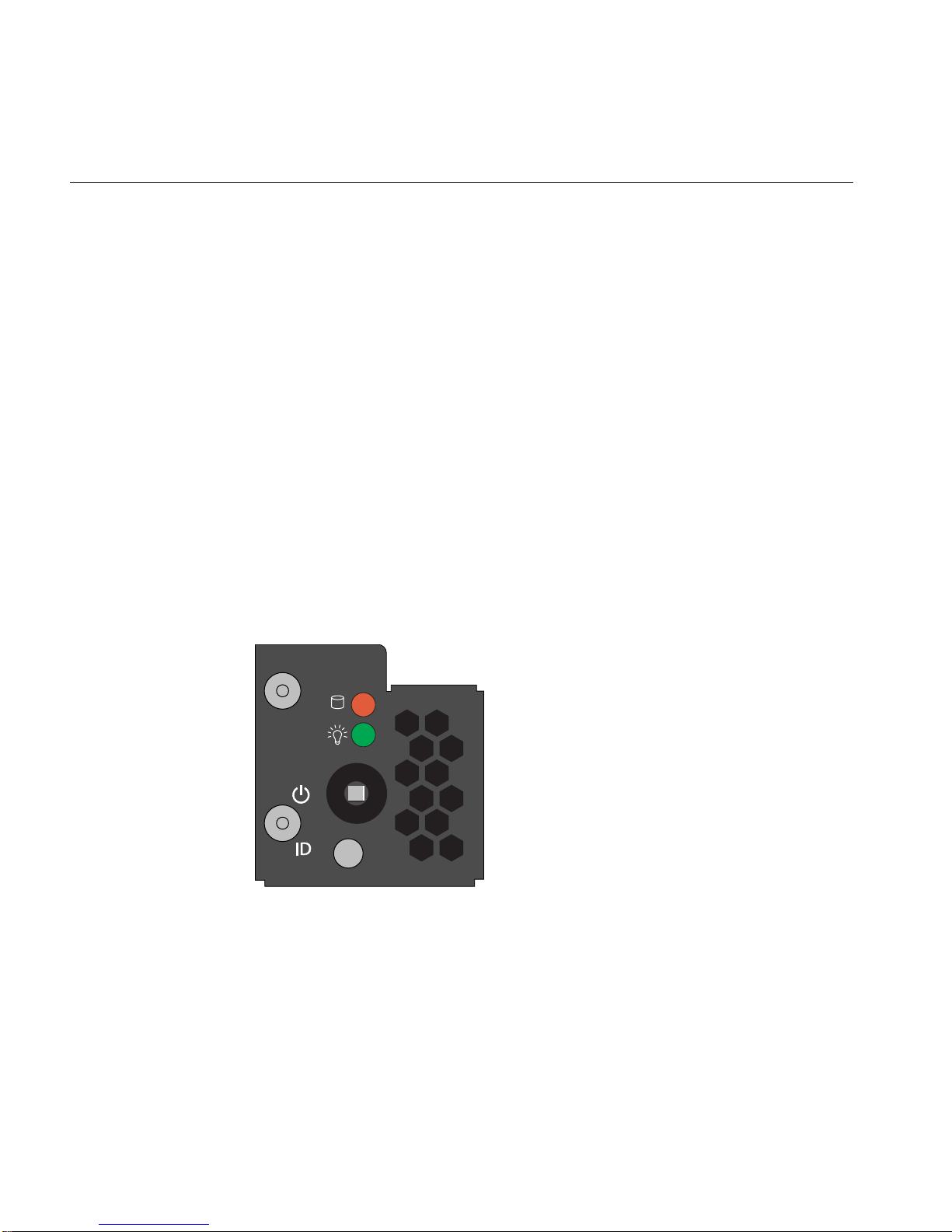
The control panel located on the front of the server chassis has three LEDs. Each LED provides
you with critical information related to the serverboard. This section explains what each LED
indicates when illuminated and any corrective action you may need to take.
Figure 3-2 Serverboard Control Panel Example
The ten-drive version of the server has its control panel on the left-front section of the chassis front
panel. The four-drive version of the server has the control panel in the upper right front area.
24 007-5843-002

HDD
Power
Universal Information LED
System Interface Overview
Channel activity for the hard disk drive array. This light indicates disk drive activity on the server
when flashing.
The LED indicates power is being supplied to the system's power supply unit. This LED should
normally be illuminated when the system is operating.
This LED will light blue when used for Unit Identifier (UID), see Figure 3-2 on page 24.
Universal Information LED States
State Indication
Solid blue Local (rear) UID button depressed
Blinking blue IPMI-activated UID
This LED will remain flashing or on until manually deactivated via the rear button or software
command.
Note: Deactivating the UID (blue indicator) LED must be performed in the same way it was
activated. If the UID LED was activated via IPMI, you can only turn the LED off via IPMI and
not with the UID button on the rear of the system.
Disk Drive Carrier LEDs
Each disk drive carrier has two LEDs.
• Green: Each drive carrier has a green LED. When illuminated, this green LED (on the front
of the drive carrier) indicates drive activity . A connection to the drive backplane enables this
LED to blink on and off when that particular drive is being accessed. See Chapter 4 for
instructions on replacing hard disk drives.
007-5843-002 25

3: System Interfaces Overview
• Red: The red LED lights to indicate a disk drive failure. If one of the drives fails, you should
also be notified by your system management software. Please refer to Chapter 4 for
instructions on replacing failed internal disk drives.
26 007-5843-002

Chapter 4
4. Internal Component Replacement and Upgrades
This chapter describes basic component replacement and upgrades for the SGI Rackable
C1110-RP6 system.
General Precautions
Care must be taken to assure that the chassis cover is in place when the server is operating to assure
proper cooling. Out of warranty damage to the system can occur if this practice is not strictly
followed.
Caution: Electrostatic Discharge (ESD) can damage electronic components. To prevent damage
to any printed circuit boards (PCBs), it is important to handle them very carefully. The following
measures are generally sufficient to protect your equipment from ESD discharge.
• Use a grounded wrist strap designed to prevent static discharge.
• Touch a grounded metal object before removing any board from its antistatic bag.
• Handle a board by its edges only; do not touch its components, peripheral chips, memory
modules or gold contacts.
• When handling chips or modules, avoid touching their pins.
Installing System DIMM Memory
Exercise extreme care when installing or removing DIMM modules to prevent electrostatic or any
other possible damage. Figure 4-1 on page 28 shows the CPU and DIMM locations.
The serverboard has sixteen 240-pin DIMM slots that can support up to 256 GB of registered ECC
DDR3-1600/1333/1066 SDRAM.
007-5843-002 27
4: Internal Component Replacement and Upgrades
Each processor on the serverboard has a memory controller that supports four DDR3 memory
channels (two DIMMs per channel). For best memory performance, install DIMMs in multiples
of eight.
Figure 4-1 Serverboard DIMM Slot Locations and Designations Example
28 007-5843-002

Note: Check with your SGI sales or service representative for approved replacement or upgrade
DIMM memory modules.
Installing Memory DIMMs
Insert each memory DIMM vertically into a slot using the information and illustrations in this
section. Pay attention to the notch along the bottom of the DIMM to prevent inserting it
incorrectly.
To install a DIMM: Insert the DIMM vertically and gently press down until it snaps into place.
Pay attention to the alignment notch at the bottom.
Repeat for all DIMMs.
To remove a DIMM: Use your thumbs to gently push the release tabs near both ends of the
memory module. This should release it from the slot.
Installing System DIMM Memory
Figure 4-2 DIMM Installation Example
Note the following operational points regarding DIMM usage in the C1110-RP6 server:
• Each processor supports four DDR3 memory channels.
• Each memory channel can support two maximum speed (1600 MT/s) DIMMs per channel.
• Mixing DIMMs with different speeds on a channel causes a default to the lowest speed.
• A 32 GB DIMM is the maximum approved DIMM capacity for the C1110-RP6.
007-5843-002 29

4: Internal Component Replacement and Upgrades
Adding PCIe Cards
The server includes two pre-installed riser cards designed specifically for use in the 1U rackmount
server chassis. One riser card supports a full-height half-depth PCI Express (PCIe) x16 card and
the other supports a low-profile x16 card inside the chassis.
A riser card has already been pre-installed into each serverboard.
Important: The PCIe cards cannot be “hot installed”.
Perform the following steps to add or replace a PCIe add-on card:
1. Power down the server.
2. Grasp the two handles on either side and pull the unit straight out of the rack until it locks
(you will hear a "click").
3. The top cover of the chassis is secured with two screws: remove them with a Phillips type
screwdriver, then place both thumbs in the indentation and push the cover back until it slides
off.
4. Lift the rear section of the top cover from the chassis to gain full access to the inside of the
server.
5. Remove the two PCIe carrier retention screws from the rear of the chassis.
6. Carefully unseat and remove the carrier and set it on a static-free surface.
7. Install the PCIe add-on (or replacement) card in the carrier.
8. Reinstall the PCIe carrier, replace the cover and return the server to operation.
30 007-5843-002

System Fans
The main serverboard is cooled by a set of seven 4-cm high-performance PWM fans. Fan speed
is constant unless modified via a setting in BIOS. Each power supply also has its own dedicated
cooling fan (one or two depending on supply type).
System Fan Failure
Replace any failed fan at your earliest convenience with the same type and model (the system can
continue to run with a failed fan). Remove the top chassis cover while the system is still running
to determine which of the fans has failed. Power down the system before replacing a fan.
Removing the power cord is also recommended as a safety precaution.
Drive Bay Installation/Removal
Hard Disk Drives: Because of their hot-swap capability, you do not need to access the inside of
the chassis or power down the system to install or replace disk drives. Proceed to the next step for
instructions.
Disk Drive Removal and Installation
Note: The operating system you use must have RAID support to enable the optional hot-swap
capability of the SATA/SAS drives.
Use caution when working around the disk drive backplane. Do not touch the backplane with any
metal objects and make sure no cables touch the backplane. Also, regardless of how many drives
are installed, all drive carriers must remain in the chassis to maintain proper airflow.
Disk Drive Removal and Installation
The system disk drives are mounted in drive carriers to simplify their instal lat ion and removal
from the chassis. These carriers also help promote proper airflow for the system. For this reason,
even empty carriers without drives installed must remain in the chassis.
007-5843-002 31

4: Internal Component Replacement and Upgrades
Mounting a Drive in a Carrier
Check with your SGI sales or service representative to obtain new or replacement hard disk drives
for the server.
Install the drive into the carrier with the printed circuit board side facing down so that the
mounting holes align with those in the carrier.
Secure the drive to the carrier with the side screws, similar to the example in Figure 4-3.
Figure 4-3 Drive Carrier Mounting Example
Installing/Removing Hot-swap Drives
To remove a carrier, push the release button located beside the drive LEDs.
Swing the handle fully out and use it to pull the disk assembly straight out of the chassis (see
Figure 4-4 on page 33).
32 007-5843-002

Disk Drive Removal and Installation
Figure 4-4 Server Disk Drive Remove Example
007-5843-002 33

4: Internal Component Replacement and Upgrades
Figure 4-5 Replacing the Drive and Carrier Example
Power Supply
The SGI Rackable C1110-RP6 server power supply is installed at the rear of the system and is
“auto-ranging” (has the capability of operating at 100 - 240 inpu t volts). To shut down the system,
press the main power button on the front of the chassis and then unplug the AC power cord(s).
Note that there are two versions of power supply used with the server as follows:
• A 450-Watt “non-redundant” single-cord power supply
• A 650-Watt redundant dual-cord power supply assembl y
The LED located directly on the front of the power supply has three states:
• Dark - no AC power is available to the supply
• Yellow - AC power available to the supply but the server is not powered on
• Green - AC power is applied and the system is on (front panel power button pushed to On)
34 007-5843-002

Power Supply Failure
If the power supply unit experiences a failure, the system will shut down if it is a 450-Watt
“non-redundant” supply and you will need to replace the power supply unit to return the
C1110-RP6 to operating status. Note that the 450-Watt unit has an On/Off rocker switch; make
sure the switch has not accidentally been turned off before replacing it.
If the power supply is 650-Watt redundant supply that experiences a failure - the server can
continue to operate until a replacement is available. Shutting down the server during replacement
of the “redundant” unit is optional.
Replacement power supply units can be obtained directly from your SGI sales or service
representative or third-party support provider.
If the power supply has failed, the LED located on the front of the power supply should be off
(unlit). Be sure the system power cord is fully plugged in to a power distribution unit that is turned
on before replacing the supply.
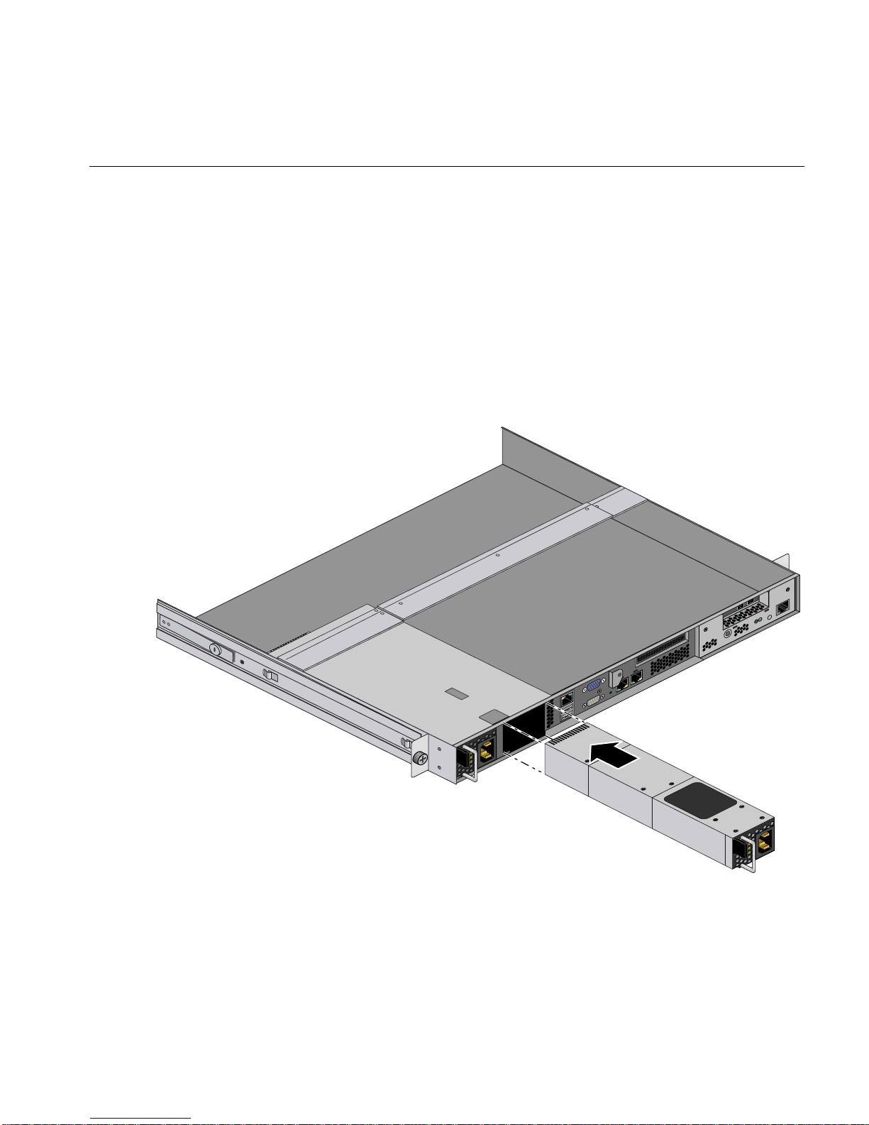
Removing the 650-Watt Redundant Power Supply
Power Supply
Use the following steps to remove a failed 650-Watt power supply from the system:
1. Unplug the AC power cord from the failed side of the redundant power supply system.
Caution: The power supply may be hot if the system has been running - make sure the supply
has at least 5 minutes to cool down.
2. Push the release tab on the front of the power supply inward. See Figure 4-6 on page 36.
3. Pull outward on the power supply handle and the unit should disengage from the internal
connector.
4. Extract the supply from the chassis by pulling it outward. Handle it with caution as the unit
may still be hot.
5. Follow the instructions in “Installing a New 650-Watt Redundant Power Supply” on
page 37.
007-5843-002 35

4: Internal Component Replacement and Upgrades
Figure 4-6 650-Watt Redundant Power Supply Removal Example
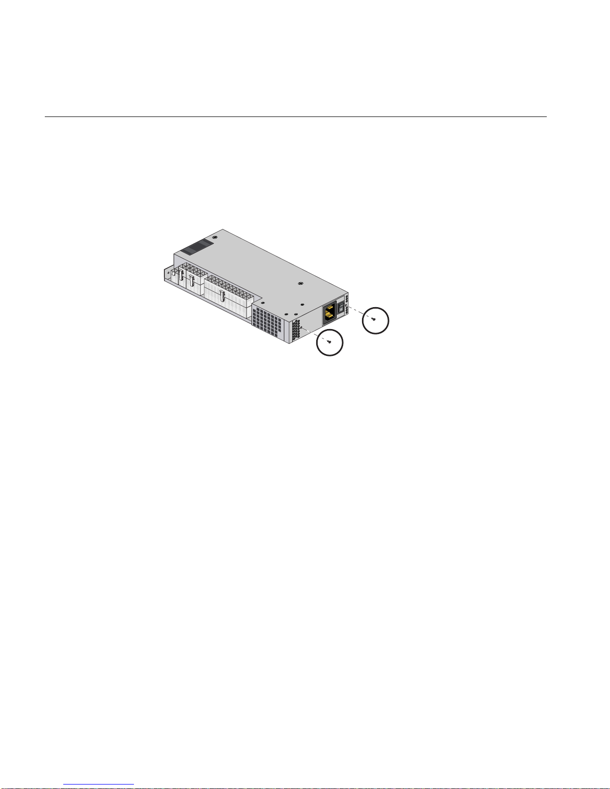
Figure 4-7 Individual 650-Watt Power Supply
36 007-5843-002
Installing a New 650-Watt Redundant Power Supply
Use the following steps to replace a failed power supply in the server:
1. Replace the failed power supply with the exact same model from SGI or another approved
vendor, contact your SGI sales or service representative for more information.
2. Insert the new unit into the chassis and push it in until seated. This may require some
moderate force but you should hear an audible “click” as the power supply is seated.
3. Reconnect the AC power cord to the supply and press the power button on the front of the
chassis to resupply power to the system if you had shut down the server.
Power Supply
Figure 4-8 650-Watt Redundant Power Supply Replacement Example
007-5843-002 37
4: Internal Component Replacement and Upgrades
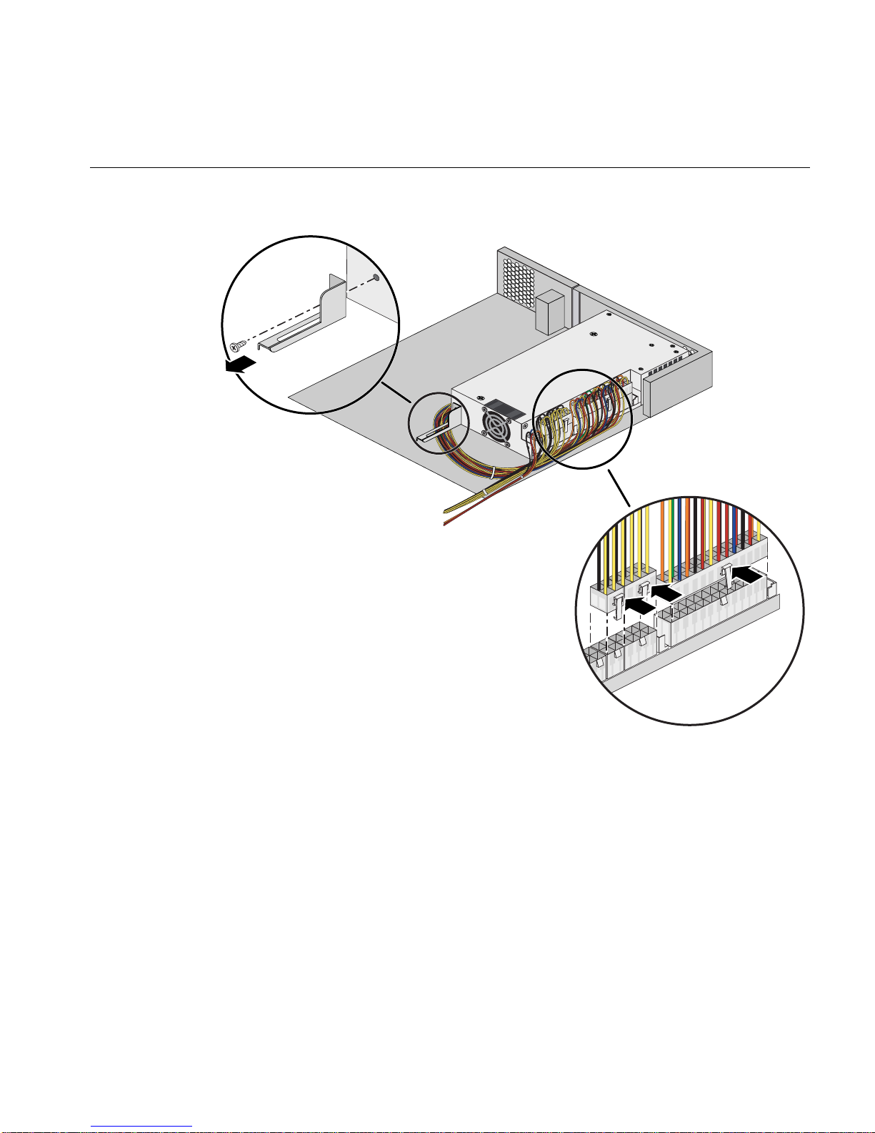
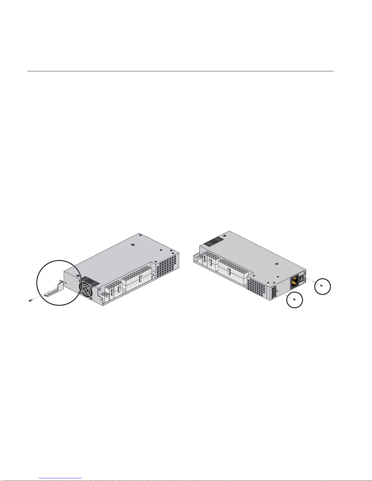
Removing the 450-Watt Non-Redundant Power Supply
If the 450-Watt “non-redundant” power supply fails, you will need to replace it as soon as possible
to restore the server to operational status. See Figure 4-9 for an example view that also shows the
two rear screw locations on the supply.
Figure 4-9 450-Watt (Non-redundant) Power Supply Example
Use the following steps to remove the failed supply:
1. Remove the rear cover portion from the server chassis; see “Remove/Replace the Chassis
Top Covers” on page 18 if you are unfamiliar with the procedure.
2. Verify the power cord is disconnected from the unit, then confirm that the supply is cool
enough to touch.
3. Reach in and undo the small, medium and large power connector cables on the outer side of
the power supply, see Figure 4-10 on page 39. Note their locations for re-installation
purposes.
4. Undo the two Phillips-head screws on the rear of the chassis that hold the 450-Watt supply
rear case in place (shown in Figure 4-9).
5. Undo the single bracket screw near the fan at the “front” of the supply, shown in
Figure 4 -10. Set all screws carefully aside for use during the re-installation process.
6. Lift the failed unit up and out of the server chassis. See the next subsection for installation of
a new power supply unit.
38 007-5843-002
Power Supply
Figure 4-10 Removing the 450-Watt Non-Redundant Power Supply
007-5843-002 39
4: Internal Component Replacement and Upgrades
Installing the 450-Watt Non-Redundant Power Supply
Use the following steps to install a new 450-Watt power supply into the server:
1. Position the new supply in the chassis so that the rear screw holes are aligned with the holes
in the rear sheetmetal and the front chassis retention bracket.
2. Use the three screws you removed in step 4 of the instructions “Removing the 450-Watt
Non-Redundant Power Supply” on page 38 to secure the unit inside the server. See
Figure 4-11.
3. Reconnect the small, medium and large power cable connectors to the outer side of the
power supply, see Figure 4-10 on page 39.
4. Attach the rear system power cord to the supply and ensure the rocker switch is set to the (|)
on position. The system fans should start up and pushing the power button on the front of the
chassis should boot the system.
5. Replace the top cover and secure it with the two top cover-retention screws. Slide the system
back into the rack as applicable.
Figure 4-11 450-Watt Power Supply Replacement Example
40 007-5843-002

Processors
I/O Chipset
Appendix A
A. System Specifications
This appendix contains technical specification information about your SGI Rackable C1110-RP6
system.
T wo Intel Xeon E5-2600 or E5-2600v2 Series processors
Intel C602 chipset series with IPMI 2.0 compliant BMC
BIOS
8-MB SMBIOS 2.3 Flash ROM
Memory Capacity
Sixteen DIMM sockets supporting registered ECC DDR3-1600/1333/1066/800 SDRAM or
unbuffered ECC/non-ECC DDR3-1600/1333/1066/800 MHz SDRAM
Memory DIMM voltage is 1.5V or 1.35V
007-5843-002 41

A: System Specifications
Disk Drive Controller
On-chip SATA controller for 3 Gb/s SATA (BIOS-assi sted software RAID 0, 1 and 10 support
available) or two SATA connectors running at 6.0 Gb/s.
Drive Bays
Four hot-swap capable 3.5-in drive bays that house standard SA T A drives or ten hot-swap capable
2.5-in SATA drive bays. Optional SAS drive configurations are available using an HBA - no te
that only RAID 0 and 1 are supported with the SAS option.
Expansion Slots
The server’s expansion slots include the following:
• One PCI-Express x16 Gen 3 full-height half-depth external slot
• One PCI-Express x16 Gen 3 low-profile external slot
Serverboard
Proprietary serverboard design and size.
Dimensions: 12.0" x 13.0" (305 x 330 mm)
Chassis
1U rackmount
Dimensions: (WxHxD) 17.2 x 1.7 x 28.2 in. (437 x 43 x 716 mm)
42 007-5843-002

Weight
Gross weight (approximate): 30 lbs. (13.6 kg.)
System Cooling
Seven 4-cm counter-rotating cooling fans plus individual power supply fans provide system
cooling.
System Input Requirements
AC Input Voltage: 100-240 VAC (auto ranging)
Rated Input Current to base (450W) supply: 5.5A (100-127V) to 2.7A (200-240V)
Rated Input Frequency: 50-60 Hz
Weight
Power Supply
Rated Output Power:
Base 450-Watt supply Rated Output Voltages: +12V, (30A max) +5V, (38A max) +3.3V, (10A
max) -12V, (0.5A max)
007-5843-002 43
A: System Specifications
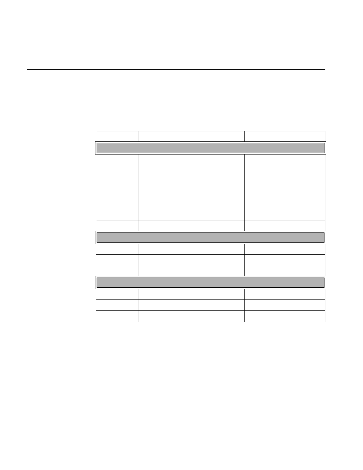
Environmental Specifications
Table A-1 lists allowable ranges for temperature, humidity, and altitude for the server.
Table A-1 Temperature, Humidity, and Altitude Specifications
Attribute Specification Rate of Change Constraints
While Product Operating
Temperature – Up to 1500m (5000ft)
+5
ºC (41ºF) to +35ºC (95ºF)
– 1525m (5000ft) to 3050m (10,000ft)
Reduce max temperature (35
305m (1000ft) of altitude above 1525m
(5000ft).
Humidity 20% to 80% Non-condensing Maximum: 10% relative
Altitude 3050m (10,000ft)
While Product Power Off
Temperature +5
Humidity 8% to 80% Non-condensing
Altitude 3050m (10,000ft)
While Product Packaged for Shipping
Temperature -40
Humidity 8% to 80% Non-condensing
Altitude 12,200m (40,000ft)
ºC (41ºF) to +45ºC (113ºF) Maximum: 20ºC/hour (36ºF/hour)
ºC (-40ºF) to +60ºC (140ºF) Maximum: 20ºC/hour (36ºF/hour)
ºC) by 1ºC per
Maximum: 10
humidity/hour
ºC/hour (18ºF/hour)
44 007-5843-002

Regulatory Compliance
Electromagnetic Emissions: FCC Class A, EN 55022 Class A, EN 61000-3-2/-3-3, CISPR 22
Class A
Electromagnetic Immunity: EN 55024/CISPR 24, (EN 61000-4-2, EN 61000- 4-3, EN 61000-4-4,
EN 61000-4-5, EN 61000-4-6, EN 61000-4-8, EN 61000-4-11)
Safety: CSA/EN/IEC/UL 60950-1 Compliant, UL or CSA Listed (USA and
Canada), CE Marking (Europe)
California Best Management Practices Regulations for Perchlorate Materials:
This Perchlorate warning applies only to products containing CR (Manganese
Dioxide) Lithium coin cells. "Perchlorate Material-special handling may apply.
See www.dtsc.ca.gov/hazardouswaste/perchlorate"
Regulatory Compliance
007-5843-002 45

 Loading...