


SGI® Origin® 3900 Server User’s Guide
007-4653-001

CONTRIBUTORS
Written by Nancy Heller
Illustrated by Dan Young
Edited by Dick Brownell
Production by Karen Jacobson
Engineering contributions by Steve Dean, Mike Peterson, Jens Petersohn, DalePurdy, Russ Anderson, Brian Larson, Steve Modica, Corky Seeber,
Bill Kellerman
COPYRIGHT
© 2003 Silicon Graphics, Inc. All rights reserved; provided portions may be copyright in third parties, as indicated elsewhere herein. No
permission is granted to copy, distribute, or create derivative works from the contents of this electronic documentation in any manner, in whole
or in part, without the prior written permission of Silicon Graphics, Inc.
LIMITED RIGHTS LEGEND
The electronic (software) version of this document was developed at private expense; if acquired under an agreement with the USA government
or any contractor thereto, it is acquired as "commercial computer software" subject to the provisions of its applicable license agreement, as
specified in (a) 48 CFR 12.212 of the FAR; or, if acquired for Department of Defense units, (b) 48 CFR 227-7202 of the DoD FAR Supplement; or
sections succeeding thereto. Contractor/manufacturer is Silicon Graphics, Inc., 1600 Amphitheatre Pkwy 2E, Mountain View, CA 94043-1351.
TRADEMARKS AND ATTRIBUTIONS
Silicon Graphics, SGI, the SGI logo, Origin, and InfiniteReality are registered trademarks, and InfinitePerformance, NUMAlink, SGIconsole, and
VPro are trademarks, of Silicon Graphics, Inc., in the U.S. and/or other countries worldwide.
MIPS is a registered trademark of MIPS Technologies, Inc. used under the license of Silicon Graphics, Inc.

Record of Revision
Version Description
001 October 2003
Original Release
007-4653-001 iii


Contents
Contents
Figures . . . . . . . . . . . . . . . . . . . . . . . . . . xiii
Tables . . . . . . . . . . . . . . . . . . . . . . . . . . xix
About This Guide. . . . . . . . . . . . . . . . . . . . . . . xxi
Audience . . . . . . . . . . . . . . . . . . . . . . . . . xxi
Important Information . . . . . . . . . . . . . . . . . . . . . xxi
Chapter Descriptions . . . . . . . . . . . . . . . . . . . . . xxii
Related Publications . . . . . . . . . . . . . . . . . . . . . xxiii
Conventions . . . . . . . . . . . . . . . . . . . . . . . xxv
Product Support . . . . . . . . . . . . . . . . . . . . . . xxv
Reader Comments . . . . . . . . . . . . . . . . . . . . . . xxvi
1. Operation Procedures . . . . . . . . . . . . . . . . . . . . . 1
Precautions . . . . . . . . . . . . . . . . . . . . . . . . . 2
ESD Precaution . . . . . . . . . . . . . . . . . . . . . . 2
Safety Precautions . . . . . . . . . . . . . . . . . . . . . 3
Connecting System Console . . . . . . . . . . . . . . . . . . . . 4
Installing Optional Components. . . . . . . . . . . . . . . . . . . 6
Adding or Removing PCI Cards . . . . . . . . . . . . . . . . . 6
Adding or Removing Disk Drives . . . . . . . . . . . . . . . . .7
Powering Server On and Off . . . . . . . . . . . . . . . . . . . . 8
Powering On Server . . . . . . . . . . . . . . . . . . . . . 8
Preparing to Power On . . . . . . . . . . . . . . . . . . . 9
Powering On at L2 Controller Touch Display . . . . . . . . . . . . 12
Powering On at System Console . . . . . . . . . . . . . . . . 21
Powering On D-brick2 . . . . . . . . . . . . . . . . . . . . 23
007-4653-001 v

Contents
Powering Off Server . . . . . . . . . . . . . . . . . . . . . 24
Preparing to Power Down . . . . . . . . . . . . . . . . . .24
Powering Off at L2 Controller Touch Display . . . . . . . . . . . . . 24
Powering Off at System Console . . . . . . . . . . . . . . . . 33
Powering Off D-brick2 . . . . . . . . . . . . . . . . . . . . 34
Monitoring Server . . . . . . . . . . . . . . . . . . . . . . . 35
2. System Overview . . . . . . . . . . . . . . . . . . . . . . . 37
Product Description . . . . . . . . . . . . . . . . . . . . . . 38
Architecture . . . . . . . . . . . . . . . . . . . . . . . . . 40
Standard System Components . . . . . . . . . . . . . . . . . . . 42
Optional System Components . . . . . . . . . . . . . . . . . . . 44
System Configurations. . . . . . . . . . . . . . . . . . . . . . 46
3. Cx-brick . . . . . . . . . . . . . . . . . . . . . . . . . . 51
Overview . . . . . . . . . . . . . . . . . . . . . . . . . 52
IP53 Node Boards . . . . . . . . . . . . . . . . . . . . . . 56
Router Board . . . . . . . . . . . . . . . . . . . . . . . 57
Power Entry Module . . . . . . . . . . . . . . . . . . . . . 57
External Components . . . . . . . . . . . . . . . . . . . . . . 58
Technical Specifications . . . . . . . . . . . . . . . . . . . . . 63
Product Options . . . . . . . . . . . . . . . . . . . . . . . 64
Important Notes . . . . . . . . . . . . . . . . . . . . . . . 64
4. IX-brick . . . . . . . . . . . . . . . . . . . . . . . . . . 65
Product Overview . . . . . . . . . . . . . . . . . . . . . . . 66
External Components . . . . . . . . . . . . . . . . . . . . . . 70
Front Panel Components . . . . . . . . . . . . . . . . . . . . 70
Rear Panel Components . . . . . . . . . . . . . . . . . . . . 72
PCI and PCI-X Card Configuration Guidelines . . . . . . . . . . . . . . .74
Important Installation Considerations . . . . . . . . . . . . . . . . 75
Supported PCI Cards . . . . . . . . . . . . . . . . . . . . . 75
PCI Card Carrier . . . . . . . . . . . . . . . . . . . . . . 76
Technical Specifications . . . . . . . . . . . . . . . . . . . . . 76
vi 007-4653-001

Contents
5. PX-brick . . . . . . . . . . . . . . . . . . . . . . . . . 79
Product Overview . . . . . . . . . . . . . . . . . . . . . . . 80
External Components . . . . . . . . . . . . . . . . . . . . . . 82
Front Panel Components. . . . . . . . . . . . . . . . . . . . 82
Rear Panel Components . . . . . . . . . . . . . . . . . . . . 84
PCI and PCI-X Card Configuration Guidelines . . . . . . . . . . . . . . 86
Important Installation Considerations . . . . . . . . . . . . . . . .87
Supported PCI and PCI-X Cards . . . . . . . . . . . . . . . . . 87
PCI Card Carrier . . . . . . . . . . . . . . . . . . . . . . 88
Technical Specifications . . . . . . . . . . . . . . . . . . . . . 88
6. X-brick . . . . . . . . . . . . . . . . . . . . . . . . . . 89
Overview . . . . . . . . . . . . . . . . . . . . . . . . . 89
External Components . . . . . . . . . . . . . . . . . . . . . . 90
Front Panel Components. . . . . . . . . . . . . . . . . . . . 90
Rear Panel Components . . . . . . . . . . . . . . . . . . . . 92
Technical Specifications . . . . . . . . . . . . . . . . . . . . . 93
7. R-brick . . . . . . . . . . . . . . . . . . . . . . . . . . 95
Overview . . . . . . . . . . . . . . . . . . . . . . . . . 95
External Components . . . . . . . . . . . . . . . . . . . . . . 98
Front Panel Components. . . . . . . . . . . . . . . . . . . . 98
Rear Panel Components . . . . . . . . . . . . . . . . . . . .100
Technical Specifications . . . . . . . . . . . . . . . . . . . . .102
8. System Control . . . . . . . . . . . . . . . . . . . . . . .103
L1 Controller . . . . . . . . . . . . . . . . . . . . . . . .106
L1 Controller Functions . . . . . . . . . . . . . . . . . . . .106
L1 Front Panel Display . . . . . . . . . . . . . . . . . . . .108
Operating L1 Controller . . . . . . . . . . . . . . . . . . . . .110
L1 Mode . . . . . . . . . . . . . . . . . . . . . . . .110
Viewing System Configuration. . . . . . . . . . . . . . . . .111
Targeting Commands . . . . . . . . . . . . . . . . . . .112
Viewing Information, Warnings, and Error Messages . . . . . . . . . .112
Powering On, Powering Off, and Resetting Brick . . . . . . . . . . .113
007-4653-001 vii

Contents
Console Mode . . . . . . . . . . . . . . . . . . . . . . 113
Console Selection . . . . . . . . . . . . . . . . . . . . 114
L2 Controller . . . . . . . . . . . . . . . . . . . . . . . 116
Home Window. . . . . . . . . . . . . . . . . . . . . . 120
Power UP Button . . . . . . . . . . . . . . . . . . . . 120
Power DOWN Button . . . . . . . . . . . . . . . . . . 120
RESET Button . . . . . . . . . . . . . . . . . . . . . 120
NMI Button . . . . . . . . . . . . . . . . . . . . . 121
DEST: Button . . . . . . . . . . . . . . . . . . . . . 121
Power Up Confirmation Window . . . . . . . . . . . . . . . . 122
Power Down Confirmation Window . . . . . . . . . . . . . . . 123
Reset Confirmation Window . . . . . . . . . . . . . . . . . . 124
NMI Confirmation Window . . . . . . . . . . . . . . . . . . 125
Command Error/Timeout Window . . . . . . . . . . . . . . . . 126
Destination Selection Window . . . . . . . . . . . . . . . . . 127
Targeting all Racks and All Bricks . . . . . . . . . . . . . . . 127
Targeting Single Brick . . . . . . . . . . . . . . . . . . 128
Targeting Range of Bricks . . . . . . . . . . . . . . . . . 129
Targeting All Bricks Within Rack . . . . . . . . . . . . . . . 130
Targeting Partition . . . . . . . . . . . . . . . . . . . 131
Operating L2 Controller . . . . . . . . . . . . . . . . . . . . 132
L2 Mode . . . . . . . . . . . . . . . . . . . . . . . 132
Viewing System Configuration . . . . . . . . . . . . . . . . 133
Targeting Commands . . . . . . . . . . . . . . . . . . 134
Viewing Information, Warnings, and Error Messages . . . . . . . . . 137
Powering On, Powering Off, and Resetting System . . . . . . . . . . 137
Console Mode . . . . . . . . . . . . . . . . . . . . . . 138
Console Selection . . . . . . . . . . . . . . . . . . . . 139
L1 Mode . . . . . . . . . . . . . . . . . . . . . . . 141
Upgrading L1/L2 Firmware . . . . . . . . . . . . . . . . . . . 142
Upgrading L1 Firmware . . . . . . . . . . . . . . . . . . . 142
Upgrading L2 Firmware . . . . . . . . . . . . . . . . . . . 143
Identifying Bricks . . . . . . . . . . . . . . . . . . . . . . 144
viii 007-4653-001

Contents
9. Power Components . . . . . . . . . . . . . . . . . . . . . .147
Power Bay . . . . . . . . . . . . . . . . . . . . . . . . .147
External Components . . . . . . . . . . . . . . . . . . . .148
Distributed Power Supplies . . . . . . . . . . . . . . . . . . .150
Technical Specifications . . . . . . . . . . . . . . . . . . . .152
Power Distribution Unit (PDU) . . . . . . . . . . . . . . . . . . .153
Power Distribution Strip (PDS) . . . . . . . . . . . . . . . . . . .154
10. SGI TP900 Storage Module . . . . . . . . . . . . . . . . . . . .155
Overview . . . . . . . . . . . . . . . . . . . . . . . . .155
External Components . . . . . . . . . . . . . . . . . . . . . .156
Front Panel Components. . . . . . . . . . . . . . . . . . . .156
Rear Panel Components . . . . . . . . . . . . . . . . . . . .158
Technical Specifications . . . . . . . . . . . . . . . . . . . . .160
Product Options . . . . . . . . . . . . . . . . . . . . . . .160
11. D-brick2 . . . . . . . . . . . . . . . . . . . . . . . . .161
Overview . . . . . . . . . . . . . . . . . . . . . . . . .161
External Components . . . . . . . . . . . . . . . . . . . . . .162
Front Panel Components. . . . . . . . . . . . . . . . . . . .162
Rear Panel Components . . . . . . . . . . . . . . . . . . . .165
Power Supply/Cooling Modules . . . . . . . . . . . . . . . .166
Operator’s Panel . . . . . . . . . . . . . . . . . . . . .167
Loop Resiliency Circuit (LRC) Modules . . . . . . . . . . . . . .168
Technical and Environmental Specifications . . . . . . . . . . . . . . .169
12. InfinitePerformance Graphics Components . . . . . . . . . . . . . . .173
V12 VPro Graphics Board . . . . . . . . . . . . . . . . . . . .174
V-brick . . . . . . . . . . . . . . . . . . . . . . . . . .176
Front Panel Components. . . . . . . . . . . . . . . . . . . .176
Rear Panel Components . . . . . . . . . . . . . . . . . . . .178
Technical Specifications . . . . . . . . . . . . . . . . . . . .179
Compositor . . . . . . . . . . . . . . . . . . . . . . . . .180
13. InfiniteReality Graphics Components . . . . . . . . . . . . . . . . .183
G-brick . . . . . . . . . . . . . . . . . . . . . . . . . .184
007-4653-001 ix

Contents
External Components . . . . . . . . . . . . . . . . . . . . 185
InfiniteReality Board Set . . . . . . . . . . . . . . . . . . . 188
Technical Specifications . . . . . . . . . . . . . . . . . . . 194
N-brick . . . . . . . . . . . . . . . . . . . . . . . . . 195
External Components . . . . . . . . . . . . . . . . . . . . 195
Technical Specifications . . . . . . . . . . . . . . . . . . . 198
14. Maintenance and Upgrade Procedures . . . . . . . . . . . . . . . . 199
Maintenance Precautions and Procedures . . . . . . . . . . . . . . . 199
Preparing Server for Maintenance or Upgrade. . . . . . . . . . . . . 200
Returning Server to Operation . . . . . . . . . . . . . . . . . 200
Using Grounding Wrist Strap . . . . . . . . . . . . . . . . . 201
Identifying Customer-replaceable Units . . . . . . . . . . . . . . 201
Installing or Replacing PCI or PCI-X Card . . . . . . . . . . . . . . . 202
Installing or Replacing Disk Drives in IX-brick . . . . . . . . . . . . . . 211
Installing SCSI Disk Drive . . . . . . . . . . . . . . . . . . 212
Removing SCSI Disk Drive . . . . . . . . . . . . . . . . . . 214
Installing or Replacing TP900 Drive Carrier Module . . . . . . . . . . . . 216
Installing TP900 Drive Carrier Module . . . . . . . . . . . . . . . 216
Replacing TP900 Drive Carrier Module . . . . . . . . . . . . . . . 219
Installing or Replacing D-brick2 Drive Carrier Module . . . . . . . . . . . 221
Installing D-brick2 Drive Carrier Module . . . . . . . . . . . . . . 221
Replacing D-brick2 Drive Carrier Module . . . . . . . . . . . . . . 226
15. Troubleshooting . . . . . . . . . . . . . . . . . . . . . . 229
Troubleshooting Chart. . . . . . . . . . . . . . . . . . . . . 230
L1 Controller Error Messages . . . . . . . . . . . . . . . . . . . 232
SGI Electronic Support. . . . . . . . . . . . . . . . . . . . . 234
A. Technical Specifications and Pinouts . . . . . . . . . . . . . . . . 237
Configuration Specifications . . . . . . . . . . . . . . . . . . . 237
Environmental Specifications . . . . . . . . . . . . . . . . . . . 238
Power Specifications . . . . . . . . . . . . . . . . . . . . . 239
Rack Specifications . . . . . . . . . . . . . . . . . . . . . . 240
Non-proprietary Connector Pinouts . . . . . . . . . . . . . . . . . 241
x 007-4653-001

Contents
L1 Port . . . . . . . . . . . . . . . . . . . . . . . . .241
External SCSI Port . . . . . . . . . . . . . . . . . . . . .242
Serial and Console Ports . . . . . . . . . . . . . . . . . . . .244
Ethernet Port . . . . . . . . . . . . . . . . . . . . . . .246
Real Time Interrupt Input and Output . . . . . . . . . . . . . . . .247
B. Safety Information and Regulatory Specifications . . . . . . . . . . . . .249
Safety Information. . . . . . . . . . . . . . . . . . . . . . .249
Regulatory Specifications . . . . . . . . . . . . . . . . . . . . .251
CMN Number. . . . . . . . . . . . . . . . . . . . . . .251
CE Notice and Manufacturer’s Declaration of Conformity . . . . . . . . . .251
Electromagnetic Emissions . . . . . . . . . . . . . . . . . . .252
FCC Notice (USA Only) . . . . . . . . . . . . . . . . . . .252
Industry Canada Notice (Canada Only) . . . . . . . . . . . . . .253
VCCI Notice (Japan Only) . . . . . . . . . . . . . . . . . .253
Chinese Class A Regulatory Notice . . . . . . . . . . . . . . .253
Korean Class A Regulatory Notice. . . . . . . . . . . . . . . .253
Shielded Cables . . . . . . . . . . . . . . . . . . . . . .254
Electrostatic Discharge . . . . . . . . . . . . . . . . . . . .254
Laser Compliance Statements . . . . . . . . . . . . . . . . . .255
Lithium Battery Statements . . . . . . . . . . . . . . . . . . .256
Index . . . . . . . . . . . . . . . . . . . . . . . . . .257
007-4653-001 xi


Figures
Figures
Figure 1-1 Connecting System Console to Multiple L2 Controllers . . . . 5
Figure 1-2 Cx-brick Power Switch. . . . . . . . . . . . . . 9
Figure 1-3 TP900 Storage Module Power Switch . . . . . . . . . 10
Figure 1-4 PDS and PDU Circuit Breaker Switches . . . . . . . . . 11
Figure 1-5 L2 Controller Touch Display . . . . . . . . . . . . 12
Figure 1-6 Home Window . . . . . . . . . . . . . . . . 13
Figure 1-7 Destination Selection Window . . . . . . . . . . . 14
Figure 1-8 Slots Section . . . . . . . . . . . . . . . . . 15
Figure 1-9 DEST Field on Home Window . . . . . . . . . . . 16
Figure 1-10 Partition Selection Window . . . . . . . . . . . . 17
Figure 1-11 Selecting Individual Partition . . . . . . . . . . . . 18
Figure 1-12 Home Window with Partition Destination . . . . . . . . 19
Figure 1-13 Power Up Confirmation Window . . . . . . . . . . 20
Figure 1-14 Slot or Unit Number . . . . . . . . . . . . . . 21
Figure 1-15 D-brick2 PSU/cooling Module Power Switch . . . . . . . 23
Figure 1-16 Home Window . . . . . . . . . . . . . . . . 25
Figure 1-17 Destination Selection Window . . . . . . . . . . . 26
Figure 1-18 Slots Section . . . . . . . . . . . . . . . . . 27
Figure 1-19 DEST Field on Home Window . . . . . . . . . . . 28
Figure 1-20 Partition Selection Window . . . . . . . . . . . . 29
Figure 1-21 Selecting Individual Partition . . . . . . . . . . . . 30
Figure 1-22 Home Window with Partition Destination . . . . . . . . 31
Figure 1-23 Power Down Confirmation Window. . . . . . . . . . 32
Figure 1-24 D-brick2 PSU/cooling Module Power Switch . . . . . . . 34
Figure 2-1 512-processor Origin 3900 Server. . . . . . . . . . . 39
007-4653-001 xiii

Figures
Figure 2-2 System Block Diagram . . . . . . . . . . . . . . 41
Figure 2-3 L-shaped Mounting Rails . . . . . . . . . . . . . 42
Figure 2-4 Standard System Components. . . . . . . . . . . . 43
Figure 2-5 10 Cx-brick System in Two Racks . . . . . . . . . . . 48
Figure 2-6 10 Cx-brick System in Three Racks . . . . . . . . . . 49
Figure 3-1 Front and Rear Views of Cx-brick . . . . . . . . . . . 52
Figure 3-2 Cx-brick Block Diagram . . . . . . . . . . . . . 55
Figure 3-3 Front View of Cx-brick . . . . . . . . . . . . . . 59
Figure 3-4 Rear View of Cx-brick . . . . . . . . . . . . . . 61
Figure 3-5 NASID Assignment . . . . . . . . . . . . . . . 62
Figure 4-1 Front View of IX-brick . . . . . . . . . . . . . . 66
Figure 4-2 IX-brick Block Diagram. . . . . . . . . . . . . . 67
Figure 4-3 IO9 Card and Daughtercard Block Diagram . . . . . . . . 69
Figure 4-4 Front Panel of IX-brick . . . . . . . . . . . . . . 71
Figure 4-5 Rear Panel of IX-brick . . . . . . . . . . . . . . 73
Figure 4-6 Numbering of IX-brick PCI-X Slots . . . . . . . . . . 74
Figure 5-1 Front View of PX-brick . . . . . . . . . . . . . . 80
Figure 5-2 PX-brick Block Diagram . . . . . . . . . . . . . 81
Figure 5-3 Front Panel of PX-brick . . . . . . . . . . . . . . 83
Figure 5-4 Rear Panel of PX-brick . . . . . . . . . . . . . . 85
Figure 5-5 Numbering of PX-brick PCI-X Slots . . . . . . . . . . 86
Figure 6-1 X-brick Block Diagram . . . . . . . . . . . . . . 90
Figure 6-2 Front Panel of X-brick . . . . . . . . . . . . . . 91
Figure 6-3 Rear Panel of X-brick . . . . . . . . . . . . . . 93
Figure 7-1 R-brick . . . . . . . . . . . . . . . . . . 95
Figure 7-2 R-brick Block Diagram . . . . . . . . . . . . . . 97
Figure 7-3 Front View of R-Brick . . . . . . . . . . . . . . 99
Figure 7-4 Rear View of R-Brick . . . . . . . . . . . . . 101
Figure 8-1 Origin 3900 System Control Network (Example) . . . . . 105
Figure 8-2 Front Panel of L1 Controller . . . . . . . . . . . 109
Figure 8-3 L2 Controller Connectors . . . . . . . . . . . . 117
Figure 8-4 Ethernet Hub Connections (Example) . . . . . . . . 118
Figure 8-5 L2 Touch Display . . . . . . . . . . . . . . 119
xiv 007-4653-001

Figures
Figure 8-6 Home Window . . . . . . . . . . . . . . . .121
Figure 8-7 Power Up Confirmation Window . . . . . . . . . .122
Figure 8-8 Power Down Confirmation Window. . . . . . . . . .123
Figure 8-9 Reset Confirmation Window . . . . . . . . . . . .124
Figure 8-10 NMI Confirmation Window . . . . . . . . . . . .125
Figure 8-11 Command Error/Timeout Window . . . . . . . . . .126
Figure 8-12 Targeting All Bricks in System . . . . . . . . . . .127
Figure 8-13 Targeting Single Brick . . . . . . . . . . . . . .128
Figure 8-14 Targeting Multiple Bricks in Rack . . . . . . . . . .129
Figure 8-15 Target Selection Window . . . . . . . . . . . . .130
Figure 8-16 Targeting Partition . . . . . . . . . . . . . . .131
Figure 8-17 Rack Numbering . . . . . . . . . . . . . . .135
Figure 9-1 Front View of Power Bay . . . . . . . . . . . . .148
Figure 9-2 Rear View of Power Bay . . . . . . . . . . . . .149
Figure 9-3 Front View of DPS . . . . . . . . . . . . . . .150
Figure 9-4 Power Distribution Units . . . . . . . . . . . . .153
Figure 9-5 Power Distribution Strip . . . . . . . . . . . . .154
Figure 10-1 Front View of TP900 Storage Module . . . . . . . . .156
Figure 10-2 Drive Carrier LED Indicators . . . . . . . . . . . .157
Figure 10-3 Rear View of TP900 Storage Module . . . . . . . . . .158
Figure 10-4 SCSI Terminator Plug . . . . . . . . . . . . . .159
Figure 11-1 Front View of D-brick2 . . . . . . . . . . . . .163
Figure 11-2 Drive Carrier Module and “Dummy” Module . . . . . . .163
Figure 11-3 Anti-Tamper Locking on D-brick2 Disk Drive . . . . . . .164
Figure 11-4 Rear View of D-brick2 . . . . . . . . . . . . . .165
Figure 11-5 Power Supply/Cooling Module . . . . . . . . . . .166
Figure 11-6 Operator’s Panel . . . . . . . . . . . . . . .167
Figure 11-7 D-brick2 Loop Resiliency Circuit (LRC) Module . . . . . .168
Figure 12-1 VPro V12 Graphics Board . . . . . . . . . . . . .174
Figure 12-2 Front View of V-Brick . . . . . . . . . . . . . .177
Figure 12-3 Rear View of V-brick . . . . . . . . . . . . . .179
Figure 12-4 Rear View of Compositor . . . . . . . . . . . . .180
Figure 13-1 Front and Rear Views of G-brick . . . . . . . . . . .184
007-4653-001 xv

Figures
Figure 13-2 Front View of G-brick . . . . . . . . . . . . . 185
Figure 13-3 Rear View of G-brick . . . . . . . . . . . . . 187
Figure 13-4 InfiniteReality Board Set . . . . . . . . . . . . 188
Figure 13-5 Ktown2 Board . . . . . . . . . . . . . . . 189
Figure 13-6 GE (Geometry Engine) Board . . . . . . . . . . . 190
Figure 13-7 RM (Raster Manager) Board . . . . . . . . . . . 191
Figure 13-8 DG5 (Display Generator) Board . . . . . . . . . . 192
Figure 13-9 Front View of N-Brick . . . . . . . . . . . . . 196
Figure 13-10 Rear View of N-Brick . . . . . . . . . . . . . 197
Figure 14-1 Removing Card Carrier. . . . . . . . . . . . . 203
Figure 14-2 Extracting Carrier Metal Filler Plate . . . . . . . . . 204
Figure 14-3 Adjusting Carrier Guide Bar . . . . . . . . . . . 205
Figure 14-4 Mounting Full-height Card in Carrier . . . . . . . . 206
Figure 14-5 Mounting Half-height Card in Carrier . . . . . . . . 207
Figure 14-6 Moving Carrier Guide Bar to Secure Half-height Card . . . . 207
Figure 14-7 Installing Bracket to Secure Half-height Card . . . . . . 208
Figure 14-8 Installing Card in Slot . . . . . . . . . . . . . 209
Figure 14-9 Seating Card in Slot . . . . . . . . . . . . . . 209
Figure 14-10 Location of SCSI Disk Drive Bays . . . . . . . . . . 211
Figure 14-11 Installing SCSI Disk Drive . . . . . . . . . . . . 213
Figure 14-12 Removing SCSI Disk Drive. . . . . . . . . . . . 215
Figure 14-13 Releasing Carrier Handle . . . . . . . . . . . . 217
Figure 14-14 Carrier Camming Lever . . . . . . . . . . . . 218
Figure 14-15 Unlocking Anti-Tamper Lock . . . . . . . . . . . 220
Figure 14-16 Unlocking Drive Carrier Module . . . . . . . . . . 222
Figure 14-17 Opening Module Handle . . . . . . . . . . . . 223
Figure 14-18 Inserting Disk Drive Module in D-brick2. . . . . . . . 224
Figure 14-19 Locking Drive Carrier Module. . . . . . . . . . . 225
Figure 14-20 Unlocking Disk Drive Module . . . . . . . . . . 226
Figure 14-21 Removing Drive Carrier Module . . . . . . . . . . 227
Figure 15-1 Full Support Sequence . . . . . . . . . . . . . 234
Figure A-1 USB Type B Connector . . . . . . . . . . . . . 241
Figure A-2 External SCSI Connector . . . . . . . . . . . . 242
xvi 007-4653-001

Figures
Figure A-3 DB9 Connector . . . . . . . . . . . . . . . .244
Figure A-4 RJ-45 Connector. . . . . . . . . . . . . . . .246
Figure A-5 Stereo Jack Connector Conductors . . . . . . . . . .247
Figure B-1 VCCI Notice (Japan Only) . . . . . . . . . . . . .253
Figure B-2 Chinese Class A Regulatory Notice . . . . . . . . . .253
Figure B-3 Korean Class A Regulatory Notice . . . . . . . . . .253
007-4653-001 xvii


Tables
Tables
Table 2-1 Configuration Specifications . . . . . . . . . . . . 46
Table 3-1 Brick Comparison Chart . . . . . . . . . . . . . 54
Table 3-2 Memory DIMM Specifications . . . . . . . . . . . 56
Table 3-3 Cx-brick Technical Specifications. . . . . . . . . . . 63
Table 3-4 Cx-brick Port Specifications . . . . . . . . . . . . 63
Table 3-5 Configurable Items of Cx-brick . . . . . . . . . . . 64
Table 4-1 Physical Specifications of the IX-brick . . . . . . . . . 76
Table 4-2 Port Specifications of the IX-brick . . . . . . . . . . 77
Table 5-1 Physical Specifications of PX-brick . . . . . . . . . . 88
Table 5-2 Port Specifications of the PX-brick . . . . . . . . . . 88
Table 6-1 X-brick Technical Specifications . . . . . . . . . . . 93
Table 7-1 R-brick Technical Specifications . . . . . . . . . . .102
Table 7-2 R-brick Port Specifications. . . . . . . . . . . . .102
Table 8-1 L1 Controller Functions . . . . . . . . . . . . .107
Table 9-1 Power Supply LED States . . . . . . . . . . . . .151
Table 9-2 Power Bay Technical Specifications . . . . . . . . . .152
Table 9-3 Power Supply Technical Specifications . . . . . . . . .152
Table 10-1 Status LEDs . . . . . . . . . . . . . . . . .157
Table 10-2 TP900 Storage Module Technical Specifications . . . . . .160
Table 10-3 Configurable Items . . . . . . . . . . . . . . .160
Table 11-1 D-brick2 Physical Specifications . . . . . . . . . . .169
Table 11-2 D-brick2 Power Specifications . . . . . . . . . . .170
Table 11-3 D-brick2 Ambient Temperature and Humidity Requirements . .171
Table 11-4 D-brick2 Environmental Requirements . . . . . . . . .171
Table 12-1 VPro V12 Connector Descriptions . . . . . . . . . .175
007-4653-001 xix

Tables
Table 12-2 V-brick Technical Specifications . . . . . . . . . . 179
Table 12-3 Compositor Ports . . . . . . . . . . . . . . 181
Table 12-4 Compositor Specifications . . . . . . . . . . . . 181
Table 13-1 DG5 Options . . . . . . . . . . . . . . . . 193
Table 13-2 DG5 Standard Connections . . . . . . . . . . . 193
Table 13-3 G-brick Specifications . . . . . . . . . . . . . 194
Table 13-4 N-brick Specifications . . . . . . . . . . . . . 198
Table 13-5 N-brick Port Specifications . . . . . . . . . . . . 198
Table 14-1 Customer-replaceable Components and Maintenance
Procedures . . . . . . . . . . . . . . . . 201
Table 15-1 Troubleshooting Chart . . . . . . . . . . . . . 230
Table 15-2 L1 Controller Messages . . . . . . . . . . . . . 232
Table A-1 Origin 3900 Server Configuration Ranges . . . . . . . 237
Table A-2 Environmental Specifications . . . . . . . . . . . 238
Table A-3 Power Specifications . . . . . . . . . . . . . 239
Table A-4 39U Rack Mechanical Specifications . . . . . . . . . 240
Table A-5 USB Type B Connector Pin Assignments . . . . . . . . 241
Table A-6 SCSI VHDCI Pin Assignments. . . . . . . . . . . 242
Table A-7 DB9 Pin Assignment . . . . . . . . . . . . . 245
Table A-8 RJ-45 Connector Pin Assignments. . . . . . . . . . 246
Table A-9 Stereo Jack Connector Conductor Assignments . . . . . . 247
xx 007-4653-001

About This Guide
This guide provides an overview of the architecture and descriptions of the major
components that compose the SGI Origin 3900 server. It also provides the standard
procedures for powering on and powering off the system, basic troubleshooting
information, and important safety and regulatory specifications.
Audience
This guide is written for owners, system administrators, and users of the SGI Origin 3900
server. It is written with the assumption that the reader has a general knowledge of
computers and computer operations.
Important Information
Warning: To avoid problems, you must ask your SGI system support engineer (SSE)
to perform all the set up, addition or replacement of parts, cabling, and service of your
SGI Origin 3900 server, with the exception of the followingitems that you can perform
yourself:
• Using your system console and your L2 controller touch display to enter commands
and perform system functions such as powering on and powering off, as described
in this guide.
• Adding and replacing PCI and PCI-X cards, as described in this guide.
• Adding and replacing disk drives in the TP900 and D-brick2 storage modules, and
in the IX-brick, as described in this guide.
• Using the On/Off switch and other switches (the reset and non-maskable interrupt
[NMI] switches on the Cx-bricks) on the front panel of your system bricks.
• Using the ESI/ops panel (operating panel) on the D-brick2.
007-4653-001 xxi

About This Guide
Chapter Descriptions
The following topics are covered in this guide:
• Chapter 1, “Operation Procedures,” provides instructions for connecting a system
• Chapter 2, “System Overview,” describes the SGI Origin 3900 server and its
• Chapter 3, “Cx-brick,” describes the function of the Cx-brick and its external
• Chapter 4, “IX-brick,” describes the function of the IX-brick and its external
• Chapter 5, “PX-brick,” describes the function of the PX-brick and its external
• Chapter 6, “X-brick” describes the function of the X-brick and its external
• Chapter 7, “R-brick,” describes the function of the R-brick and its external
• Chapter 8, “System Control,” describes the function of the L1 and L2 controllers and
• Chapter 9, “Power Components,” provides an overview of the power bay, power
• Chapter 10, “SGI TP900 Storage Module,” describes the function of the TP900
• Chapter 11, “D-brick2,” describes the function of the D-brick2 storage module and
console to your server, powering on and powering off your server, and monitoring
your server.
architecture, and provides a brief description of the system components and
configurations.
components (for example, connectors and LEDs).
components (for example, connectors and LEDs).
components (for example, connectors and LEDs).
components (for example, connectors and LEDs).
components (for example, connectors and LEDs).
provides instructions for using the controllers.
distribution unit, and power distribution strip.
storage module and its external components.
its external components.
• Chapter 12, “InfinitePerformance Graphics Components” provides an overview of
the V12 VPro graphics board, the V-brick, and the compositor.
• Chapter 13, “InfiniteReality Graphics Components” provides an overview of the
G-brick and the N-brick.
• Chapter 14, “Maintenance and Upgrade Procedures,” provides instructions for
installing and removing the customer-replaceable components of your server.
• Chapter 15, “Troubleshooting,” provides recommended actions if problems occur
on your server.
xxii 007-4653-001

• Appendix A, “Technical Specifications and Pinouts‚" provides physical,
• Appendix B, “Safety Information and Regulatory Specifications‚" lists all regulatory
Related Publications
The following SGI documents are relevant to the SGI Origin 3900 server:
• SGI Total Performance 900 Storage System User’s Guide
• SGI Total Performance 9100 (2Gb TP9100) Storage System User’s Guide
• SGI TP9400 and SGI TP9500 RAID User ’s Guide
• SGIconsole Hardware Connectivity Guide
• SGI L1 and L2 Controller Software User’s Guide
• Man pages (online)
Related Publications
environmental, and power specifications for your server. Also included are the
pinouts for the non-proprietary connectors.
information related to use of the SGI Origin 3900 server in the United States and
other countries. It also provides a list of safety instructions to follow when
installing, operating, or servicing your server.
(P/N 007-4428-xxx)
This fully illustrated guide explains how to operate and maintain the SGI Total
Performance 900 (TP900) SCSI storage system.
(P/N 007-4522-xxx)
This fully illustrated guide explains how to operate and maintain the 2Gb SGI Total
Performance 9100 Fibre Channel storage system.
(P/N 007-4304-xxx)
This fully illustrated guide explains how to operate and maintain the SGI TP9400
and SGI TP9500 Fibre Channel storage systems.
(P/N 007-4340-xxx)
This fully illustrated guide explains how to connect the SGIconsole to the various
SGI server and graphics system configurations. SGIconsole is a multi-server
management system that manages and monitors multiple servers throughout a
customer’s computing environment, whether those servers are on site or remote.
(P/N 007-3938-xxx)
This guide describes how to use the L1 and L2 controller commands at your system
console to monitor and manage your SGI system.
Man pages locate and print the titled entries from the online reference manuals.
007-4653-001 xxiii

About This Guide
You can obtain SGI documentation, release notes, or man pages in the following ways:
• See the SGI Technical Publications Library at http://docs.sgi.com. Various formats
are available. This library contains the most recent and most comprehensive set of
online books, release notes, man pages, and other information.
• The release notes, which contain the latest information about software and
documentation in this release, are in a file named README.SGI in the root
directory of the SGI ProPack for Linux Documentation CD.
• You can also view man pages by typing man <title> on a command line.
SGI systems include a set of IRIX man pages, formatted in the standard UNIX “man
page” style. Important system configuration files and commands are documented on
man pages. These are found online on the internal system disk (or CD-ROM) and are
displayed using the man command. For example, to display the man page for the
xscsidisktest command, type the following on a command line:
man xscsidisktest
References in the documentation to these pages include the name of the command and
the section number in which the command is found.
For additional information about displaying man pages using the man command, see
man(1).
In addition, the apropos command locates man pages based on keywords. For example,
to display a list of man pages that describe disks, type the following on a command line:
apropos disk
For information about setting up and using apropos, see apropos(1).
xxiv 007-4653-001

Conventions
Conventions
The following conventions are used throughout this document:
Convention Meaning
Command This fixed-space font denotes literal items such as commands, files,
routines, path names, signals, messages, and programminglanguage
structures.
variable The italic typeface denotes variable entries and words or concepts
being defined. Italic typeface is also used for book titles.
user input This fixed-space font denotes literal items that the user enters in
interactive sessions. Output is shown in nonbold, fixed-space font.
[ ] Brackets enclose optional portions of a command or directive line.
... Ellipses indicate that a preceding element can be repeated.
man page(x) Man page section identifiers appear in parentheses after man page
names.
GUI element This font denotes the names of graphical user interface (GUI)
elements such as windows, screens, dialog boxes, menus, toolbars,
icons, buttons, boxes, fields, and lists.
Product Support
SGI provides a comprehensive product support and maintenance program for its
products, as follows:
• If you are in North America, contact the Technical Assistance Center at
+1 800 800 4SGI or contact your authorized service provider.
• If you are outside North America, contact the SGI subsidiary or authorized
distributor in your country.
007-4653-001 xxv

About This Guide
Reader Comments
If you have comments about the technical accuracy, content, or organization of this
document, contact SGI. Be sure to include the title and document number of the manual
with your comments. (Online, the document number is located in the front matter of the
manual. In printed manuals, the document number is located at the bottom of each
page.)
You can contact SGI in any of the following ways:
• Send e-mail to the following address: techpubs@sgi.com
• Use the Feedback option on the Technical Publications Library Web page:
http://docs.sgi.com
• Contact your customer service representative and ask that an incident be filed in the
SGI incident tracking system.
• Send mail to the following address:
Technical Publications
SGI
1600 Amphitheatre Pkwy., M/S 535
Mountain View, California 94043-1351
SGI values your comments and will respond to them promptly.
xxvi 007-4653-001

Chapter 1
1. Operation Procedures
This chapter explains how to operate your SGI Origin 3900 server in the following
sections:
• “Precautions” on page 2
• “Connecting System Console” on page 4
• “Installing Optional Components” on page 6
• “Powering Server On and Off” on page 8
• “Monitoring Server” on page 35
007-4653-001 1
1: Operation Procedures
Precautions
ESD Precaution
!
Before operating your server, familiarize yourself with the safety information in the
following sections:
• “ESD Precaution” on page 2
• “Safety Precautions” on page 3
Caution: Observe all ESD precautions. Failure to do so can result in damage to the
equipment.
Wear an SGI-approved wrist strap when you handle an ESD-sensitive device to eliminate
possible ESD damage to equipment. Connect the wrist strap cord directly to earth
ground.
2 007-4653-001

Safety Precautions
!
Precautions
Warning: Before operating or servicing any part of this product, read the “Safety
Information” on page 249.
Danger: Keep fingers and conductive tools away from high-voltage areas. Failure to
follow these precautions will result in serious injury or death. The high-voltage areas
of the server are indicated with high-voltage warning labels.
Caution: Power off the server only after the system software has been shut down in an
orderly manner. If you power off the server before you halt the operating system, data
may be corrupted.
Note: A lithium battery is installed on the IO9 card located in the IX-brick.
Warning: Only qualified SGI service personnel should replace the lithium battery.
007-4653-001 3

1: Operation Procedures
Connecting System Console
The system console enables you to perform the following activities:
• Monitor your server by reading the server’s status and error message information
generated and displayed by the L1 and L2 controllers.
• Enter L1 and L2 controller commands to monitor or change particular server
functions. You can, for example, monitor the speed of fans for a particular brick. See
your SGI L1 and L2 Controller Software User’s Guide for descriptions of these
commands.
• Power on or power off individual bricks or all bricks (except for the storage
modules) in your server.
If you connect a console that contains SGIconsole software, you can perform the
functions listed above, manage multiple systems from one console, and have boundary
scan capabilities. Boundary scan capabilities enable an SGI system support engineer
(SSE) to test the interconnections of your server.
To connect a system console, follow these steps:
1. If your server has multiple L2 controllers, connect each L2 controller (via its
Ethernet port) to an Ethernet hub.
2. Connect your console to the Ethernet hub or to the Console port of an L2 controller
as shown in Figure 1-1. The connection of the system console to the Console port
requires a special cable that you can purchase from SGI. This configuration also
requires terminal emulator software (not available from SGI).
Note: You can also use SGIconsole to monitor your server. SGIconsole connects to
multiple L2 controllers via an Ethernet hub. For instructions on how to connect
SGIconsole to your server, see your SGIconsole Hardware Connectivity Guide.
4 007-4653-001

DISPLAY
(Front door)
System console
Ethernet
hub
Connecting System Console
Ethernet cable
IX-brick
Cx-brick
Cx-brick
Cx-brick
Cx-brick
L2 controller
L2 controller
R-brick
R-brick
Cx-brick
Cx-brick
Cx-brick
Cx-brick
Ethernet
USB
NUMAlink 3
Xtown2 (RS-422 signals used)
RS-232
Figure 1-1 Connecting System Console to Multiple L2 Controllers
007-4653-001 5

1: Operation Procedures
Installing Optional Components
Besides adding a system console, you can add or replace the following hardware items
on your Origin 3900 server:
• Peripheral component interface (PCI) cards
• Disk drives
The sections that follow discuss these activities in more detail.
Warning: You can add or replace only the items listed in this section. For your safety
and for the protection of your server, contact your SGI system support engineer (SSE)
to install any hardware items not listed in this section.
Warning: Before installing, operating, or servicing any part of this product, read the
“Safety Information” on page 249.
Adding or Removing PCI Cards
The PCI-X based I/O system, an industry standard for connecting peripherals to a
processor, is the primary I/O system for the Origin 3900 server. The hardware
components of thisI/O systemare contained inIX- andPX- bricks. The IX-brick provides
the base I/O functionality for the server and 12 PCI/PCI-X slots. One of the 12 slots is
reserved for a system PCI card. If additional PCI slots are required beyond the 11
remaining slots in the IX-brick, PX-bricks are configured into the server. Each PX-brick
provides an additional 12 PCI/PCI-X slots.
For instructions on how to install or remove PCI cards, see “Installing or Replacing PCI
or PCI-X Card” on page 202.
6 007-4653-001

Adding or Removing Disk Drives
The IX-brick provides the system boot functions and has one or two low-profile SCSI disk
drives. For instructions on how to install or remove these disk drives, see “Installing or
Replacing Disk Drives in IX-brick” on page 211.
The TP900 is a SCSI-based disk storage module that provides JBOD (just a bunch of
disks) mass storage. Each TP900 can contain up to 8 disk drives. For instructions on how
to install or remove these disk drives, see “Installing or Replacing TP900 Drive Carrier
Module” on page 216.
The D-brick2 is a Fibre Channel-based disk storage enclosure that provides JBOD mass
storage. Each D-brick2 can contain up to 16 disk drives. For instructions on how to install
or remove these disk drives,see “Installingor Replacing D-brick2 Drive Carrier Module”
on page 221.
Installing Optional Components
007-4653-001 7

1: Operation Procedures
Powering Server On and Off
This sectionexplains how to power on and power off individual bricksor your entire SGI
Origin 3900 server, as follows:
• “Powering On Server” on page 8
• “Powering Off Server” on page 24
You can poweron and power off individual bricks or the entire server at the L2 controller
touch display on the front door of rack 001 (the leftmost rack when viewing the front of
the racks). Or if your server has a system console, you can power on and power off
individual bricks or the entire server at the system console.
Powering On Server
This section describes how to prepare to power on your server, and how to power on
your server by using either of the following:
• L2 controller touch display
• System console
The L1 controller display, located on the front of each brick, should display L1 running
once the power-on procedure starts.
Note: If you have a problem while powering on and an error message appears on your
L2 controller touch display, your console, or the L1 controller display, see your online log
files and, see“L1 Controller Error Messages” on page 232 to learn what the error message
indicates and how to resolve the problem.
8 007-4653-001

Preparing to Power On
Powering Server On and Off
To prepare to power on your server, follow these steps:
1. Check to ensure that the cabling between the power distribution unit (PDU) and the
wall power-plug receptacle is secure.
2. For each individual brick that you want to power on, make sure that the PWR
(power) switch is set to the 1 (on) position, as shown in Figure 1-2. When the power
switch is on and power is supplied to the brick, the L1 controller of the brick powers
on. The 12-VDC LED of the brick illuminates green when 12 VDC is present.
Power switch on
48 VDC 34.0 A
Electrical
12 VDC 20 A
PWR
X
I
O
2
Rating
NUMAlink 1 Port A
Power OK O I ConsoleL1
NODE 3
Router
NODE 2
Inlet Brd
NODE 1
12 V
NODE 0
48 V
D
C
B
A
NUMAlink 8 Port H NUMAlink 7 Port G NUMAlink 6 Port F
Port
X
X
I
I
O
O
3
1
3
2
1
0
N2N3INT LINK N1
D
C
B
A
N0
X
I
O
0
Figure 1-2 Cx-brick Power Switch
007-4653-001 9

1: Operation Procedures
3. If you plan to power on a D-brick2, or an entire rack of D-brick2s, see “Powering On
D-brick2” on page 23.
4. To power on a TP900 storage module, set the power switch of each TP900 storage
module to the 1 (on) position.
Note: The standard configuration of the TP900 storage module has one power
supply, as shown in Figure 1-3. You can add a second power supply to the TP900
system toprovide n+1redundant power. The second power supply is identical tothe
first power supply and would be located in the lower-right section of the TP900
storage module. Both power switches must be in the 1 (on) position to provide
redundant power.
CHANNEL 2 CHANNEL 1
OUTPUT
GOOD
FAULT
AC power input
Power switch
Figure 1-3 TP900 Storage Module Power Switch
10 007-4653-001

Powering Server On and Off
5. Make sure that the circuit breaker switches of the power distribution unit (PDU)
and power distribution strip (PDS) shown in Figure 1-4 are in the on position.
PDS
Circuit breaker
switch
PDU
Figure 1-4 PDS and PDU Circuit Breaker Switches
007-4653-001 11

1: Operation Procedures
Powering On at L2 Controller Touch Display
This section describes how to power on individual bricks or the entire server from your
L2 controller touch display (see Figure 1-5), which is located on the front door of rack 001.
D
E
S
T
:
S
G
I
L
L
2
2
C
-
0
o
0
n
1
tro
S
lle
/N
P
r, F
o
L
w
x
irm
e
x
r: O
x
w
x
x
a
x
re
F
x [fir
F
x
x
.x
e
s
x
to
.x
P
rm
o
w
]
e
r
U
P
P
o
w
e
r
D
O
W
N
R
E
S
E
T
N
M
I
r *
s
*
[5
7
B
r
ic
k
s
]
Figure 1-5 L2 Controller Touch Display
For instructions on how to use the L2 controller touch display, see “L2 Controller” on
page 116.
12 007-4653-001

Powering Server On and Off
The home window, shown in Figure 1-6, displays the following items:
• Firmware (xx.xx.x) version of the L2 controller.
• Rack number (L2-001) of the L2 controller to which the L2 controller touch display is
connected.
• System serial number (Lxxxxxxx).
• Server name in parentheses (firestorm).
• Power status (Power: OFF) for the bricks designated in the destination (DEST:)
field. For this example, all slots in all racks (r * s *), which amounts to 57 bricks, are
powered off.
• Four command buttons (Power UP, Power DOWN, RESET, and NMI) that when
selected activate a confirmation window for the command. The command is sent to
the bricks that are listed in the DEST: field after you okay the command from the
confirmation window.
• DEST: button that enables you to select the bricks that will receive a command. In
addition, to the right of this button is an area that lists the current brick selection.
For this example, all slots in all racks (r * s *), which amounts to 57 bricks, are
selected to receive a command.
SGI L2 Controller, Firmware
L2-001 S/N
Lxxxxxxx [firestorm]
xx.xx.x
Power: OFF
Power UP
Power DOWN
RESET
NMI
DEST:
Figure 1-6 Home Window
007-4653-001 13
r * s * [57 Bricks]

1: Operation Procedures
To power on selected bricks, a partition, or the entire server, follow these steps:
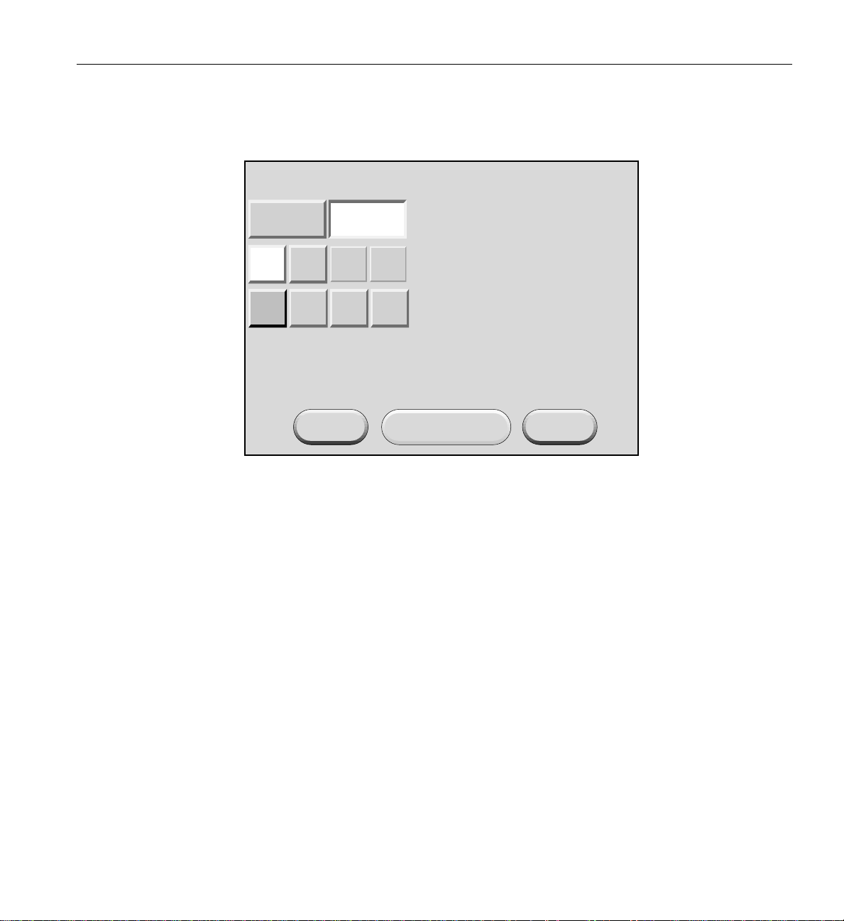
1. Touch the DEST: button in the home window and the destination selection window,
shown in Figure 1-7 appears. Use this window to select the bricks or partitions that
you want to power on.
PartitionRack/Slot
ALL
CLR
001
002 003 004
101
102
<<
>>
New DEST: r * s *
Apply
Figure 1-7 Destination Selection Window
ALL
CancelReset DEST
CLR
14 007-4653-001

Powering Server On and Off
2. The bricks are selected by their rack and slot/unit number, or by partition. Select
ALL in the display if you want to power on all the bricks in the server. You can also
select the bricks in all the slots of multiple racks, but you cannot select slots for
multiple racks.
If you want to power on individual bricks, select the rack that contains the bricks
that you want to power on from the Rack/Slot segment of the display. A box
appears that lists the slot numbers for all of the bricks in the selected rack (see
Figure 1-8).
ALL
CLR
002 003 004
001
101
102
PartitionRack/Slot
<<
>>
Slots:
007
023
ALL
011
015
027 031
CLR
019
035
New DEST: r 1 s 7, 15, 27, 35
Apply
Figure 1-8 Slots Section
CancelReset DEST
3. Select the slot number of each brick that you want to power on. (Figure 1-8 shows
slots 007, 015, 027, and 035 selected). The New DEST: field lists your selections.
After you complete your selections, select Apply.
007-4653-001 15
1: Operation Procedures
The home window shown in Figure 1-9 appears. The DEST: field of this window
indicates that you want to power on the bricks that reside in slots 07, 15, 27, and 35
of rack 001.
SGI L2 Controller, Firmware
L2-001 S/N
Lxxxxxxx [firestorm]
xx.xx.x
Power: OFF
Power UP
Power DOWN
RESET
NMI
DEST:
Figure 1-9 DEST Field on Home Window
r 1 s 7, 15, 27, 35 [ 4 Bricks ]
16 007-4653-001

Powering Server On and Off
4. If you want to power on a partition, select Partition from the destination selection
window. The partition selection window, shown in Figure 1-10, appears.
PartitionRack/Slot
ALL
CLR
001
002 003 004
<<
>>
New DEST: p *
Apply
Figure 1-10 Partition Selection Window
CancelReset DEST
007-4653-001 17

1: Operation Procedures
5. You can select all partitions by selecting ALL on the partition selection window, or
you can select a single partition or multiple partitions by selecting the individual
partition numbers. Figure 1-11 shows partition 001 selected.
PartitionRack/Slot
ALL
CLR
001
002 003 004
<<
>>
New DEST: p 1
Apply
Figure 1-11 Selecting Individual Partition
CancelReset DEST
18 007-4653-001
Powering Server On and Off
6. The New DEST: field shows p 1, which indicates that partition 001 was selected as
the new destination. If you select Apply, your selection is confirmed and the home
window, shown in Figure 1-12, appears. The DEST: field shows p 1 [2 Bricks], which
indicates that the bricks in partition 1 are the new destination.
SGI L2 Controller, Firmware
L2-001 S/N
Lxxxxxxx [firestorm]
xx.xx.x
Power: OFF
Power UP
Power DOWN
RESET
NMI
DEST:
Figure 1-12 Home Window with Partition Destination
p 1 [2 Bricks]
007-4653-001 19
1: Operation Procedures
7. After you have selected the destination of the bricks you want to power on, select
Power UP on the home window, and the power up confirmation window, shown in
Figure 1-13, appears. This window indicates which bricks will receive the Power UP
command. In this example, the window indicates that all slots (bricks) in all racks (r
*s*) will be powered on. If you select OK, the power-up operation is confirmed, and
the home window appears. Selecting Cancel stops the power-on operation, and the
home window appears.
SGI L2 Controller, Firmware xx.xx.x
L2-001 S/N Lxxxxxxx [firestorm]
Power: OFF
Press the "OK" button to issue the
"r * s * power up" command.
OK Cancel
Figure 1-13 Power Up Confirmation Window
20 007-4653-001
Powering On at System Console
To power on your server at the system console, follow these steps:
1. At your console, switch to L2 mode by pressing Ctrl+T.
2. From the L2 prompt (L2>), power on an individual brick by entering the following
command. (If you want to power on the entire server, proceed to step 3.)
L2> r <rack#> s <slot#> pwr u
For example, to power on a Cx-brick in rack 1, slot 07, enter the following:
L2> r 1 s 7 pwr u
The slot number is the lowest unit number that the brick occupies within a rack. For
example, in Figure 1-14, the lowest Cx-brick is identified as U07. The next lowest
Cx-brick is identified as U11, and so on.
39
38
37
36
35
34
33
32
31
30
29
28
27
26
25
24
23
22
21
20
19
18
17
16
15
14
13
12
11
10
9
8
7
6
5
4
3
2
1
Powering Server On and Off
IX-brick
Cx-brick
Cx-brick
Cx-brick
Cx-brick
Power bay
Power bay
Figure 1-14 Slot or Unit Number
007-4653-001 21

1: Operation Procedures
If you want to power on several selected bricks from a rack at the same time, you
must enter the rack number followed by the slot numbers of the bricks you want to
power on. For example, to power on bricks in slots 7 and 11 of rack 4, enter the
following command:
L2> r 4 s 7,11 pwr u
If you want to power on the bricks that reside in the same slot in multiple racks, you
must enter the number of the racks followed by the slot number of the bricks you
want to power on. For example, to power on the bricks in slot 11 of racks 3 and 4,
enter the following command:
L2> r 3, 4 s 11 pwr u
Note: To avoid problems with your server, do not try to power on multiple slots for
multiple racks at the same time.
3. If you want to power on the entire server, enter the following command:
L2> pwr u
(The default setting for the pwr u command is all racks and all slots.)
4. From the L2 prompt, display the system configuration by entering the following
command:
L2> config
This command lists the bricks in the server and each brick’s system controller
address.
22 007-4653-001

Powering On D-brick2
Powering Server On and Off
Before powering on the D-brick2, confirm that the following is true:
• Drives are seated in the correct bays and blank plates are fitted in any empty bays.
• Ambient temperature is within the specified range of 10 °Cto40°C (50 °Fto104°F).
• The rack power distribution unit (PDU) and power distribution strip (PDS) are on.
To power on the D-brick2, follow these steps:
1. Connect an AC power cord to each PSU/cooling module.
2. Connect the AC power cords to the PDS.
3. Turn the power switch on each PSU/cooling module to the “on” position (1 = on, 0
= off). The location of the power switch on the D-brick2 PSU/cooling module is
shown in Figure 1-15.
Power on/off switch
Figure 1-15 D-brick2 PSU/cooling Module Power Switch
(I = on)
AC power input
The green “PSU good” LED illuminates. Also, the “power on” LED on the ESI/ops panel
of each module turns green when AC power is present.
If the “power on” LED on the ESI/ops panel does not illuminate, or if the amber
“system/ESI fault” LED illuminates, verify that you followed all steps. For
troubleshooting tips, see the SGI Total Performance 9100 (2Gb TP9100) Storage System
User’s Guide or contact your service provider.
007-4653-001 23

1: Operation Procedures
Powering Off Server
Preparing to Power Down
You can power off individual bricks or your entire server from the L2 controller touch
display (located on the front door of rack 001) or from the system console, as explained
in the sections that follow.
Note: To verify that the power-off procedure is proceeding properly, make sure that the
On/Off LEDs andthe 48-VDC LEDs turn off and that your L1 controllers display that the
server is powering off for each segment of the procedure. If you have a problem while
powering off and an error message appears on your L2 controller touch display, your
console, or the L1 controller display, see your online log files and the information in “L1
Controller Error Messages” on page 232 to learn what the error message indicates and
how to resolve the problem.
If you are logged on to the server, log out.
If you are planning to power down a D-brick2 or an entire rack of D-brick2s, see
“Powering Off D-brick2” on page 34.
Powering Off at L2 Controller Touch Display
This section describes how to use the L2 controller touch display to power off individual
bricks or the entire server. If you have multiple racks whose L2 controllers are
interconnected at an Ethernet hub, you can power off any brick in those racks or the
entire server at the L2 controller touch display on the front door of rack 001.
For instructions on how to use the L2 controller touch display, see “L2 Controller” on
page 116.
24 007-4653-001

Powering Server On and Off
To power off selected bricks, a partition, or the entire server, follow these steps:
1. Select the DEST: button from the home window and the destination selection
window, shown in Figure 1-17, appears. Use this window to select the bricks or
partition you want to power off.
SGI L2 Controller, Firmware
L2-001 S/N
Lxxxxxxx [firestorm]
Power: OFF
Power UP
Power DOWN
RESET
NMI
DEST:
Figure 1-16 Home Window
r * s * [57 Bricks]
xx.xx.x
007-4653-001 25

1: Operation Procedures
2. The bricks are selected by their rack and slot/unit number, or by partition. Select All
in the display if you want to power off all the bricks in all the racks in the server.
You can also select the bricks in all the slots of multiple racks, but you cannot select
slots for multiple racks.
PartitionRack/Slot
ALL
CLR
001
002 003 004
101
102
<<
>>
New DEST: r * s *
Apply
Figure 1-17 Destination Selection Window
ALL
CancelReset DEST
CLR
26 007-4653-001

Powering Server On and Off
If you want to power off individual bricks, select the rack that contains the bricks
that you want to power off from the Rack/Slot segment of the display. A box
appears that lists the slot numbers for all of the bricks in the selected rack (see
Figure 1-18).
ALL
CLR
002 003 004
001
101
102
PartitionRack/Slot
<<
>>
Slots:
007
023
ALL
011
015
027 031
CLR
019
035
New DEST: r 1 s 7, 15, 27, 35
Apply
Figure 1-18 Slots Section
CancelReset DEST
3. Select the slot number of each brick that you want to power off. (Figure 1-18 shows
slots 007, 015, 027, and 035 selected). The New DEST: field lists your selections.
After you complete your selections, select Apply.
007-4653-001 27

1: Operation Procedures
The home window shown in Figure 1-19 appears. The DEST: field of this window
indicates that you want to power off the bricks that reside in slots 07, 15, 27, and 35
of rack 001.
SGI L2 Controller, Firmware
L2-001 S/N
Lxxxxxxx [firestorm]
xx.xx.x
Power: OFF
Power UP
Power DOWN
RESET
NMI
DEST:
Figure 1-19 DEST Field on Home Window
r 1 s 7, 15, 27, 35 [ 4 Bricks ]
28 007-4653-001
Powering Server On and Off
4. If you want to power off a partition, select Partition from the destination selection
window. The partition selection window, shown in Figure 1-20, appears.
PartitionRack/Slot
ALL
CLR
001
002 003 004
<<
>>
New DEST: p *
Apply
Figure 1-20 Partition Selection Window
CancelReset DEST
007-4653-001 29

1: Operation Procedures
5. You can select all partitions by selecting ALL on the partition selection window, or
you can select a single partition or multiple partitions by selecting the individual
partition numbers. Figure 1-21 shows partition 001 selected.
PartitionRack/Slot
ALL
CLR
001
002 003 004
<<
>>
New DEST: p 1
Apply
Figure 1-21 Selecting Individual Partition
CancelReset DEST
30 007-4653-001

Powering Server On and Off
6. The New DEST: field shows p 1, which indicates partition 001 was selected as the
new destination. If you select Apply, your selection is confirmed and the home
window, shown in Figure 1-22, appears. The DEST: field shows p 1 [2 Bricks], which
indicates that the two bricks in partition 1 are the new destination.
SGI L2 Controller, Firmware
L2-001 S/N
Lxxxxxxx [firestorm]
xx.xx.x
Power: OFF
Power UP
Power DOWN
RESET
NMI
DEST:
Figure 1-22 Home Window with Partition Destination
p 1 [2 Bricks]
007-4653-001 31

1: Operation Procedures
7. After you have selected the destination of the bricks you want to power off, select
Power DOWN from the home window; the power down confirmation window,
shown in Figure 1-23, appears. This window indicates which bricks will receive the
Power DOWN command. In this example, the window indicates that all slots
(bricks) in all racks (r * s*) will be powered off. If you select OK, the power-off
operation is confirmed and the home window appears. Selecting Cancel stops the
power-off operation and the home window appears.
SGI L2 Controller, Firmware xx.xx.x
L2-001 S/N Lxxxxxxx [firestorm]
Power: ON
Press the "OK" button to issue the
"r * s * power down" command.
OK Cancel
Figure 1-23 Power Down Confirmation Window
32 007-4653-001

Powering Off at System Console
To power off your server at the system console, follow these steps:
1. At your console, switch to L2 mode by pressing Ctrl+T.
2. From the L2 prompt (L2>), power off an individual brick by typing the following
command. (If you want to power off the entire server, proceed to the next step.)
L2> r <rack#> s <slot#> pwr d
For example, to power off a Cx-brick in rack 1, slot 07, type the following:
L2> r 1 s 7 pwr d
The slot number is the lowest unit number that the brick occupies within a rack (see
Figure 1-14 on page 21).
If you want to power off several bricks from a rack at the same time, you must type
the rack number followed by the slot numbers of the bricks you want to power off.
For example, to power off bricks in slots 7 and 11 of rack 4, type the following:
L2> r 4 s 7,11 pwr d
If you want to power off bricks that reside in the same location in multiple racks,
you must type the number of the racks followed by the slot number of the bricks
you want to power off for each rack. For example, to power off the bricks in slot 11
of racks 3 and 4, type the following:
L2> r 3, 4 s 11 pwr d
Powering Server On and Off
Caution: To avoid problems with your server, do not try to power off multiple slots
!
007-4653-001 33
for multiple racks at the same time.
3. If you want to power off all the bricks in all the racks, type the following command:
L2> pwr d
(The default setting for the pwr d command is all racks and all slots.)
4. From the L2 prompt, display the brick configuration information by typing the
following command:
L2> config
This command lists all the bricks in the server and each brick’s system controller
address.
1: Operation Procedures
Powering Off D-brick2
The L1 controller display for each brick should display Powered Down once the power
down procedure completes.
Before powering off the D-brick2, confirm that the following has occurred:
• All system users have been notified and are logged off.
• Disk data has been backed up as appropriate.
To power off a D-brick2 enclosure, follow these steps:
1. Move the power switch on the rear of each PSU/cooling module to the “off”
position (position I = on, O = off). The location of the power switch on the D-brick2
PSU/cooling module is shown in Figure 1-24.
Power on/off switch
Figure 1-24 D-brick2 PSU/cooling Module Power Switch
(I = on)
AC power input
2. Unplug the power cable from the PSU/cooling module(s) as appropriate. For
example, you would follow this step when you are replacing a module.
3. If you are shutting down all of the D-brick2s in a rack, you may want to move the
PDU breaker switch to the “off” position.
The LEDs on the back of the unit should turn dark a few seconds after you power off the
PSU/cooling module.
34 007-4653-001

Monitoring Server
Monitoring Server
You can monitor your SGI Origin 3900 server from the following sources:
• L1 controller display - All bricks (except the TP900 and D-brick2) contain an L1
controller display that displays information about the brick. For example, you can
see if the fans on a particular brick are operating properly.
• If your server has a system console, you can view the status and error messages
generated by the L1 and L2 controllers in your server. You can also use the system
console to input L1 and L2 commands to manage and monitor your server.
• If your server has SGIconsole, you can view the status and error messages
generated by the L1 and L2 controllers in your server and you can use various
software tools, such as VACM, Console Manager, and PCP, to manage and monitor
your server. See the SGIconsole Start Here guide for descriptions of these tools and
for references to other documents with information about these tools.
007-4653-001 35


Chapter 2
2. System Overview
This chapter provides an overview of the physical and architectural aspects of your
Origin 3900server. System configurations and components are described and illustrated.
This chapter includes the following sections:
• “Product Description” on page 38
• “Architecture” on page 40
• “Standard System Components” on page 42
• “Optional System Components” on page 44
• “System Configurations” on page 46
007-4653-001 37

2: System Overview
Product Description
The SGI Origin 3900 server is the latest model in the SGI Origin 3000 family of servers. It
can range from 4 MIPS processors and 1 GB of memory to 512 MIPS processors and 1024
GB of memory. Furthermore, the SGI Origin 3900 servers can be clustered to increase the
number of processors from 512 to thousands of processors.
Like all models of the Origin 3000 family of servers, this server is based on SGI
NUMAflex shared-memory architecture. The main differences between this server and
the other Origin 3000 series servers are as follows:
• The Origin 3900 server uses a new packaging scheme that offers four times the
• The Origin 3900 server uses an enhanced system topology (also referred to as a
processor/memory density over the other Origin 3000 series servers. The Origin
3900 can have up to 128 processors and 256 GB of memory in a single rack; thus,
enabling you to have a high-productivity supercomputer in a smaller footprint. For
example, a 512-processor Origin 3800 server requires 16 compute racks. An Origin
3900 server that has 512 processors requires only 4 compute racks and 2 router racks
(see Figure 2-1).
fat-tree topology) that provides two times the bandwidth capabilities over the
hypercube topology, which is the topology used by the other Origin 3000 series
servers.
The hardware of the Origin 3900 server is fully compatible with the existing Origin 3000
series servers; therefore, you can upgrade an existing Origin 3000 series server with the
new Origin3900 hardware. This upgradedoes require converting theexisting hypercube
topology to the enhanced topology.
38 007-4653-001

Product Description
Figure 2-1 512-processor Origin 3900 Server
007-4653-001 39

2: System Overview
Architecture
The Origin 3900 sever is based on SGI NUMAflex architecture: the third-generation
shared-memory system architecture that is the basis of SGI HPC servers and
supercomputers. The NUMAflex architecture is specifically engineered to provide
technical professionals with superior performance and scalability in a design that is easy
to deploy, program, and manage. It has the following features:
Shared access of processors, memory, and I/O -The NUMAflex architecture contains
two key components that enable applications to share the processors, memory, and I/O
devices: the Bedrock ASIC and the NUMAlink interconnect (see Figure 2-2).
• Each Bedrock ASIC in the system is an 8-input by 6-output crossbar that acts as the
memory controller between processors and memory in the system for both local
and remote memory accesses.
• The NUMAlink interconnect channels information between all the bricks in the
system to create a single contiguous system memory of up to 1 TB and enables
every processor in a system direct access to every I/O slot in the system.
Together, the Bedrock ASICs and the NUMAlink interconnect enable efficient access to
processors, local and remote memory, and I/O devices without the bottlenecks
associated with switches, backplanes, and other commodity interconnect technologies.
System scalability - The NUMAflex architecture incorporates a low-latency,
high-bandwidth interconnect that is designed to maintain performance as it scales in the
following dimensions: computing, I/O, and memory. For example, the computing
dimension can range from 4 to 512 processors in a single system image (SSI).
Efficient resource management--The NUMAflex architecture is designed to run complex
models, and because the entire memory space is shared, large models fit into memory
with no programming restrictions. Rather than waiting for all of the processors to
complete their assigned tasks, the system dynamically reallocates memory, resulting in
faster time to solution.
40 007-4653-001

Architecture
CPU
CPU
CPU
CPU
CPU
CPU
CPU
CPU
CPU
CPU
CPU
CPU
CPU
CPU
CPU
CPU
CPU
Memory
CPU
CPU
CPU
Bedrock
CPU
Memory
CPU
CPU
CPU
Bedrock
Compute brick
Memory
Memory
CPU
Memory
CPU
CPU
CPU
Bedrock
Compute brick
CPU
Memory
CPU
CPU
CPU
Bedrock
Bedrock
Bedrock
Memory
Memory
Bedrock
Bedrock
Router
Board
Router
ASIC
Router
ASIC
Router
Board
Figure 2-2 System Block Diagram
To I/O devices
NUMAlink
interconnect
To I/O devices
Router
Board
Router
ASIC
Router
ASIC
Router
Board
Compute brick
Memory
Memory
Bedrock
Bedrock
Compute brick
Memory
Memory
Bedrock
Bedrock
Memory
Bedrock
Memory
Bedrock
CPU
CPU
Memory
CPU
CPU
Bedrock
CPU
CPU
Memory
CPU
CPU
Bedrock
CPU
CPU
CPU
CPU
CPU
CPU
CPU
CPU
CPU
CPU
CPU
CPU
CPU
CPU
CPU
CPU
CPU
CPU
CPU
CPU
CPU
CPU
CPU
CPU
007-4653-001 41

2: System Overview
Standard System Components
The SGI Origin 3900 server features the following standard components (see Figure 2-4):
• Cx-brick - This compute brick contains 4, 8, 12, or 16 MIPS processors, 1 GB to 32 GB
of memory, and a router board. The Cx-brick is equivalent to four C-bricks and one
R-brick in one enclosure. For more information about the Cx-brick, see Chapter 3,
“Cx-brick”.
• IX-brick - This I/O brick is a Crosstalk-to-PCI-X based I/O expansion subsystem
that provides the base I/O functionality for the system. For more information about
the IX-brick, see Chapter 4, “IX-brick”.
• R-brick - This router brick transfers messages between the Cx-bricks via the
NUMAlink interconnect. The R-brick is required for systems that contain more than
four Cx-bricks. For more information about the R-brick, see Chapter 7, “R-brick”.
• L2 controller - This rack-level controller manages the bricks within a rack (not
shown in Figure 2-4). For more information about the L2 controller, see Chapter 8,
“System Control”.
• Power components - The power components of the Origin 3900 server consist of
power distribution units (PDUs) and power bays. The PDUs filter input power,
protect against over-current conditions, and remove power from the racks (not
shown in Figure 2-4). The power bay inputs AC voltage and outputs 48 VDC and 12
VDC standby voltage to the bricks within a rack. For more information about these
power components, see Chapter 9, “Power Components”.
• Rack - This industry-standard 19-inch rack contains 39 units (Us) of vertical space
that can seat bricks and power bays. (Each U is equivalent to 1.75 inches.) This rack
uses two parallel L-shaped mounting rails to support each brick within the rack.
L-shaped horizontal
mounting rails
19 in.
Figure 2-3 L-shaped Mounting Rails
42 007-4653-001

Standard System Components
The 39U rack, as shown in Figure 2-4, has front and rear doors that have keylocks to
prevent unauthorized accessto the system. The rack also hascable entry/exit areas at the
bottom of the rack and cable management hardware in the rear of the rack.
The 39U rack is mounted on four casters, two of which are swivel castors. The castors
enable the rack to be rolled out of a shipping crate and to its placement at the customer
site. The base of the rack has seismic tie-down attachment points and leveling pads. For
mechanical specificationsof the 39U rack, see Appendix A, “Technical Specifications and
Pinouts”.
IX-brick
Cx-brick
Power bay
Figure 2-4 Standard System Components
007-4653-001 43

2: System Overview
Optional System Components
The Origin 3900 server can contain the following optional components:
• System console - This console enables you to power on and power off the system,
monitor the system, and enter L1 controller and L2 controller commands.
• I/O bricks - The Origin 3900 server supports the following I/O bricks: IX-brick,
PX-brick, and X-brick. The IX- and PX-bricks are Crosstalk-to-PCI-X based I/O
expansion subsystems that can seat up to 12 PCI-X cards. The difference between
these two brick types is that the IX-brick has a DVD-ROM and one or two SCSI disk
drives. For more information about the IX-brick, see Chapter 4, “IX-brick”. For more
information about the PX-brick, see Chapter 5, “PX-brick”.
The X-brick provides up to four XIO slots for your SGI Origin 3900 server. For more
information about the X-brick, see Chapter 6, “X-brick”.
• Disk storage components - The Origin 3900 supports the following disk storage
components:
• For a Fibre Channel solution that supports JBOD (just a bunch of disks)
configurations, SGI offers the D-brick2. For more information about the
D-brick2, see Chapter 11, “D-brick2”.
• For a SCSI (small computer system interface) JBOD solution, SGI offers the SGI
Total Performance 900 (TP900) storage module. For more information about the
TP900, see Chapter 10, “SGI TP900 Storage Module”.
• For a Fibre Channel solution that supports both JBOD and RAID configurations,
SGI offers the SGI Total Performance 9100 [2Gb TP9100] storage system. For
more information about the 2Gb TP9100, see the SGI Total Performance 9100 (2Gb
TP9100) Storage System User's Guide (007-4522-00x).
• For a Fibre Channel RAID solution, SGI offers the SGI Total Performance 9400
(TP9400) storage system and the SGI Total Performance 9500 (TP9500) storage
system. For more information about the TP9400 and TP9500 storage systems,
see the SGI Total Performance 9400 and SGI Total Performance 9500 RAID User's
Guide (007-4304-00x).
44 007-4653-001

Optional System Components
• Tape storage components - The Origin 3900 server supports the following tape
drives:
• DLT 8000 - 8000 native (6-MB/s transfer rate, 40-GB storage capacity)
• DLT 8000 - 7000 emulation (5-MB/s transfer rate, 35-GB storage capacity)
• LTO (15-MB/s transfer rate, 100-GB storage capacity)
• SDLT220 (11-MB/s transfer rate, 110-GB storage capacity)
• SDLT320 (16-MB/s transfer rate, 160-GB storage capacity)
• T9840 (10-MB/s transfer rate, 20-GB storage capacity)
• T9840B (20-MB/s transfer rate, 20-GB storage capacity)
• T9940A (10-MB/s transfer rate, 60-GB storage capacity)
• T9940B (30-MB/s transfer rate, 200-GB storage capacity)
For detailed information on the supported tape drives, see the following website:
http://sales.corp.sgi.com/products/storage/stk/matrices.html
• Graphics components - The Origin 3900 server supports InfinitePerformance or
InfiniteReality graphics. The main components of the InfinitePerformance graphics
system are the VPro V12 graphics board, the V-brick, and the compositor (CBOB).
For more information about the InfinitePerformance graphics components, see
Chapter 12, “InfinitePerformance Graphics Components”. The main components of
the InfiniteReality graphics system are the G-brick and the N-brick, which are
discussed in detail in Chapter 13, “InfiniteReality Graphics Components”.
007-4653-001 45

2: System Overview
System Configurations
The Origin 3900 server supports a wide range of system configurations to serve your
computing needs (see Table 2-1). The Origin 3900 server scales in 4-processor increments
and in two Cx-brick increments. (The Cx-bricks do not have to be fully populated with
processors.) The Origin 3900 server also supports a memory-only Cx-brick that enables
you to increase the amount of memory without increasing the number of processors.
Table 2-1 Configuration Specifications
System Size Maximum Number
of Processors
1 Cx-brick 16 32 0 1
2 Cx-bricks 32 64 0 1
4 Cx-bricks 64 128 0 1
6 Cx-bricks 96 192 2 1 or 2
8 Cx-bricks 128 256 2 2
10 Cx-bricks 160 320 4 2 or 3
12 Cx-bricks 192 384 4 2 or 3
14 Cx-bricks 224 448 4 3 or 4
16 Cx-bricks 256 512 4 3 or 4
18 Cx-bricks 288 576 18 5 or 6
20 Cx-bricks 320 640 18 5 or 6
22 Cx-bricks 352 704 20 5 or 6
24 Cx-bricks 384 768 20 5 or 6
26 Cx-bricks 416 832 22 6
28 Cx-bricks 448 896 22 6
Maximum Amount
of Memory in GB
RequiredNumber
of Metarouters
RequiredNumber
of Racks*
30 Cx-bricks 480 960 24 6
32 Cx-bricks 512 1024 24 6
* This number does not include I/O and storage racks.
46 007-4653-001

System Configurations
The following configuration rules apply to the Origin 3900 servers:
• When the server contains more than four Cx-bricks, the server must be configured
with metarouters (also referred to as R-bricks). For example, servers that contain 6
or 8 Cx-bricks require two metarouters. The third column of Table 2-1 indicates the
number of required metarouters for the supported system sizes. The system
topology supports a 200 MB/s per processor bisection bandwidth from 32
processors to 512 processors.
• Each server or partition within the server must contain one system IX-brick that
provides the base I/O functionality.
• Each server supports up to eight I/O bricks.
• When the server contains a memory-only Cx-brick, the memory-only Cx-brick must
be paired with a Cx-brick that has at least four processors.
• You can configure your server as a single system, or you can divide it into partitions
that operate as separate systems. For example, you can configure an Origin 3900
server that has 512 processors as a single 512-processor system, or you can divide it
into as many as eight separate systems. The size of a partition can be configured to
match your job size. For more information about partitioning, see Partitioning for
Systems that Contain Cx-bricks (007-4426-00x).
• An Origin 3900 server is configured so that the server resides in the smallest
footprint possible and so that the Cx-bricks are placed low within the racks. The
number of compute racks is determined by the number of Cx-bricks, I/O bricks,
and storage bricks in the server. For example, the smallest footprint for a 10
Cx-brick system is two compute racks; however, if an additional rack is required to
house the I/O and storage bricks, a compute rack, rather than an I/O rack, is added
to the system. The Cx-bricks are placed low within the three compute racks and the
I/O and storage bricks are placed above the Cx-bricks (see Figure 2-5 and
Figure 2-6).
007-4653-001 47

2: System Overview
Cx-brick
Cx-brick
IX-brick
Cx-brick
Cx-brick
Cx-brick
Cx-brick
Power bay
Power bay
R-brick
R-brick
R-brick
R-brick
Cx-brick
Cx-brick
Cx-brick
Cx-brick
Power bay
Power bay
Figure 2-5 10 Cx-brick System in Two Racks
48 007-4653-001

PX-brick
IX-brick
Cx-brick
Cx-brick
Cx-brick
Cx-brick
Power bay
Power bay
PX-brick
R-brick
R-brick
Cx-brick
Cx-brick
Cx-brick
Cx-brick
Power bay
Power bay
D-brick2
D-brick2
R-brick
R-brick
D-brick2
PX-brick
Cx-brick
Cx-brick
Power bay
Power bay
System Configurations
s
g
i
s
g
i
s
g
i
s
g
i
s
g
i
s
g
i
s
g
i
s
g
i
s
g
i
s
g
i
s
s
g
g
i
i
s
g
i
s
g
i
s
g
i
s
s
g
g
i
i
s
g
i
s
g
i
s
g
i
s
s
g
g
i
i
s
g
i
s
g
i
s
g
i
s
g
i
s
g
i
s
g
i
s
g
i
s
g
i
s
g
i
s
g
i
s
g
i
s
g
i
s
g
i
s
g
i
s
g
i
s
g
i
s
g
i
s
g
i
s
g
i
s
g
i
s
g
i
s
g
i
s
g
i
s
g
i
s
g
i
s
g
i
Figure 2-6 10 Cx-brick System in Three Racks
007-4653-001 49


Chapter 3
3. Cx-brick
This chapter describes the function and physical components of the Cx-brick.
Specifically, it includes the following information:
• “Overview” on page 52
• “External Components” on page 58
• “Technical Specifications” on page 63
• “Product Options” on page 64
• “Important Notes” on page 64
007-4653-001 51

3: Cx-brick
Overview
The Cx-brick is a new brick type for the SGI Origin 3000 series product line; it is
equivalent to four Origin 3000 series C-bricks and one R-brick in one 4U-high enclosure
(see Figure 3-1).
The hardware that is equivalent to four C-bricks is contained on four IP53 node boards;
one IP53 node board is equal to one C-brick. The Cx-brick supports the following two
types of IP53 node boards:
• Four-processor node board that has 8 MB of L2 cache per processor and up to 8
DIMMs.
• Zero-processor node board that has up to 8 DIMMs (no L2 cache).
The hardware that is equivalent to the R-brick is contained on a single printed circuit
board (PCB). The key component on this PCB is the router ASIC, which is the same ASIC
used in the R-brick. This router ASIC enables the internal IP53 node boards to connect to
other Cx-bricks via the NUMAlink 3 interconnect. This PCB also transfers I/O and
system control signals between I/O devices and the IP53 node boards via XIO ports.
Front view
Rear view
Figure 3-1 Front and Rear Views of Cx-brick
52 007-4653-001

Overview
The Cx-brick has the same modular features of the current Origin 3000 series bricks and
is fully compatible with the 3000 series architecture. For example, the Cx-brick has the
following characteristics:
• Uses the same fans and L1 display as the Origin 3000 series bricks
• Is rack mountable in an Origin 3000 series rack
• Uses the same Bedrock and router ASICs
• Supports MIPS processors
Note: The Cx-brick does not support Intel processors.
• Receives power (48 VDC) from a power bay
• Uses the same control system (L1 and L2 controllers)
• Supports partitioning
• Is compatible with SGI’s current graphics product line offerings: InfiniteReality and
InfinitePerformance
• Uses the IRIX operating system (versions 6.5.18 or greater)
007-4653-001 53

3: Cx-brick
Table 3-1 lists some of the differences between the Cx-brick and the C- and R-bricks.
Table 3-1 Brick Comparison Chart
Characteristic Cx-brick C-brick R-brick
Processors 0 to 16 2 or 4 N/A
Processor boards 4 IP53 node boards 2 PIMMs N/A
Memory 1 GB to 32 GB 1 GB to 8 GB N/A
DIMMs 8 per node board 8 per brick N/A
NUMAlink ports 4 internal and 4 external 1 external 8 external
XIO ports 1 to 4 external (1 per IP53 node board) 1 0
The following sections provide more detail about the components that make up the
Cx-brick (see Figure 3-2):
• “IP53 Node Boards” on page 56
• “Router Board” on page 57
• “Power Entry Module” on page 57
Warning: To prevent personal injury, or damage to your system, only trained SGI
system support engineers (SSEs) can service the internal components of the Cx-brick.
54 007-4653-001

Overview
XIO connector
XIO connector
DIMM
DIMM
DIMM
DIMM
DIMM
DIMM
DIMM
DIMM
IP53 node board
L2 cache
L2 cache
Bedrock
ASIC
L2 cache
L2 cache
Processor D
Processor C
Processor B
Processor A
System control
NUMAlink 3
XIO
IP53
node
board
IP53
node
board
IP53
node
board
IP53
node
board
L1 display
MegArray
connectors
Router board
Router
ASIC
L1
controller
Power entry module
XIO connector
XIO connector
NUMAlink 3
connector
NUMAlink 3
connector
NUMAlink 3
connector
NUMAlink 3
connector
Console port
L1 port
Power connector
Figure 3-2 Cx-brick Block Diagram
007-4653-001 55

3: Cx-brick
IP53 Node Boards
The Cx-brick consists of one to four IP53 node boards. Each IP53 node board has the
following components:
• 1 Bedrock application-specific integrated circuit (ASIC) that enables communication
between the processors, memory, network, and I/O devices.
• 0 or 4 processors (labeled A, B, C, and D in Figure 3-2).
• 8 MB of L2 cache for each processor to reduce memory latency.
• 2 MegArray connectors (1 XIO and 1 NUMAlink 3) to connect the IP53 node board
to the router board.
• 2, 4, 6, or 8 dual-inline memory modules (DIMMs) that provide from 1 GB to 8 GB of
local memory. The Cx-brick supports 512 MB and 1 GB single DIMM sizes (see
Table 3-2).
Table 3-2 Memory DIMM Specifications
DDR SDRAM
Memory Kit Single DIMM Size
Technology
1 GB with premium integrated directory memory 512 MB 128 Mbits
2 GB with premium integrated directory memory 1 GB 256 Mbits
Your SGI support service engineer (SSE) can increase or decrease the size of
memory by adding or removing DIMM pairs.
56 007-4653-001

Router Board
Overview
The router board of the Cx-brick contains the following components:
• Router ASIC (same ASIC as used in the R-brick) that makes up the NUMAlink 3
interconnect. The NUMAlink 3 interconnect routes messages between the compute
nodes in the system.
• L1 controller that monitors and manages your Cx-brick, and generates status and
error messages that appear on the liquid crystal display (LCD) located on the
Cx-brick front panel (see Figure 3-3 on page 59).
• Four NUMAlink 3 connectors that connect to router boards in other Cx-bricks or to
R-bricks.
• Two internal XIO connectors. Each internal XIO connector connects to a separate
XIO jumper board that has two external XIO connectors. The two XIO jumper
boards provide a total of four external XIO connectors for the Cx-brick.
• Four sets of MegArray connectors (one set for each IP53 node board). Each set of
connectors consists of one XIO connector and one NUMAlink 3 connector.
• One 48V-to-2.5V converter for the router ASIC.
Power Entry Module
The Cx-brickcontains a power entry module (also known as theinlet board)that receives
48 VDC power from the power bay and converts it to 12 VDC (for the node boards). The
power entry module, which controls fan speed, also contains the following items:
• Four sets of 48V-to-12V converters (one set for each IP53 node board).
• Power switch to power on and power off the Cx-brick.
• Power connector to connect the Cx-brick to the power bay.
• Console serial port (DB-9 connector) for the system console connection.
• L1 port (USB connector) for the L1-to-L2 controller connection.
• Connector that connects the power entry module to the L1 display.
• Eight power LEDs (described in “External Components” on page 58).
007-4653-001 57

3: Cx-brick
External Components
The Cx-brick is a 4U-high brick that contains the following front-panel items (see
Figure 3-3):
• L1 display is a 2-line by 12-character liquid crystal display (LCD) that displays
status and error messages that the L1 controller generates.
• On/Off button with LED enables you to manually power on and power off the
Cx-brick.
• LEDs:
• On/Off button LED illuminates green when the internal components are
• Service required LED illuminates orange to indicate that an item is not
• Failure LED illuminates red to indicate that a failure has occurred and the
• Reset switch resets the Cx-brick internal processors and ASICs. This reset will cause
a memory loss. (See non-maskable interrupt [NMI] to perform a reset without
losing register data.)
powered on.
functioning properly (for example, a fan is off), but the Cx-brick is still
operating.
Cx-brick is down.
• NMI switch resets the Cx-brick internal processors and ASICs and writes the
contents of the registers and memory to a /var/adm/crash file. (This switch is not
used by the memory-only Cx-brick.)
• Three fans provide N+1 redundant cooling for the brick.
58 007-4653-001

External Components
Fans
Failure LED
Service required LED
L1 display
On/Off switch
with LED
Reset switch
NMI switch
Figure 3-3 Front View of Cx-brick
007-4653-001 59

3: Cx-brick
The Cx-brick has the following rear-panel items (see Figure 3-4):
• Four NUMAlink connectors connect the Cx-brick to other Cx-bricks and/or
R-bricks. NUMAlink 6 (port F) and NUMAlink 1 (port A) connect to another
Cx-brick. NUMAlink 7 (port G) and NUMAlink 8 (port H) connect to R-bricks.
Note: For a system that contains four Cx-bricks, all four NUMAlink ports connect to
Cx-bricks.
Each NUMAlink connector has two LEDs: one LED illuminates yellow to indicate
that the Cx-brick and the brick to which it is connected are powered on and the
other LED illuminates green to indicate that the link is established between the
Cx-brick and the brick to which it is connected.
• Four XIO connectors can connect the Cx-brick to IX-, PX-, and/or X-bricks. The XIO
connector numbers indicate the IP53 node board to which it connects; for example,
XIO0 connects to IP53 node board 0. XIO1 connects to IP53 node board 1, and so on.
Each XIO connector has two LEDs: one LED illuminates yellow to indicate that the
IP53 node board and the brick to which it is connected are powered on and the
other LED illuminates green to indicate that the link is established between the IP53
node board and the I/O brick to which it is connected.
• One power connector connects the Cx-brick to a power bay via a DC power cable.
• One power switch powers on the L1 controller when moved to the 1 position;
moving it to the 0 position powers off the L1 controller.
• One L1 port connects the Cx-brick’s L1 controller to the L2 controller.
• One Console port connects the Cx-brick’s L1 controller to a system console.
• Sixteen heartbeat LEDs: each IP53 node board has four LEDs that indicate
processor activity. (For example, N0 A is the LED for processor A of IP53 node board
0.)
• Four INT LINK LEDs indicate that the connections between the four Bedrock
ASICs and the router board are okay. (For example, INT LINK 0 is the LED for the
connection between the Bedrock ASIC on IP53 node board 0 and the router board.)
• Eight Power OK LEDs:
• One LED for 12-V power illuminates green when the power switch is in the On
(1) position and the power bay supplies 12 VDC to the brick.
• One LED for 48-V power illuminates green when the power bay supplies
48 VDC to the brick at the request of the L1 controller.
60 007-4653-001

External Components
13
3
2
1
0
N2INT LINK N1
D
C
B
A
N3
D
C
B
A
N0
• One LED for the router board indicates that the router board is receiving its
required power.
• One LED for the power inlet module (also referred to as the power entry
module) indicates that the inlet board is receiving its required power.
• Four LEDs, one for each IP53 node board, indicate that each IP53 node board is
receiving its required power.
NUMAlink LEDs XIO LEDs
One LED lights yellow,
the other lights green
48 VDC 34.0 A
Electrical
12 VDC 20 A
PWR
X
I
O
2
Rating
NUMAlink 1 Port A
Power OK O I ConsoleL1
Router
Inlet Brd
12 V
48 V
NODE 3
NODE 2
NODE 1
NODE 0
One LED lights yellow,
the other lights green
Port
X
X
I
I
O
O
3
1
D
C
B
A
NUMAlink 8 Port H NUMAlink 7 Port G NUMAlink 6 Port F
3
2
1
0
N2N3INT LINK N1
D
C
B
A
X
I
O
0
N0
Node board (N3)
INT LINK LEDs
heartbeat LEDs
007-4653-001 61
Figure 3-4 Rear View of Cx-brick
Node board (N2 and N1)
heartbeat LEDs
Node board (N0)
heartbeat LEDs

3: Cx-brick
The IP53 node boards have the following node address space identifier (NASID)
assignment (see Figure 3-5):
• IP53 node board 1 is NASID n
• IP53 node board 2 id NASID n+1
• IP53 node board 0 id NASID n+2
• IP53 node board 3 id NASID n+3
0l
PWR
X
X
I
I
O
XIO-2 NASID n+1 XIO-3 NASID n+3XIO-1 NASID n XIO-0 NASID n+2
D
C
NUMAlink 1 Port A
NUMAlink 8 Port H NUMAlink 7 Port G NUMAlink 6 Port F
B
A
O
1
3
DAD
3
2
1
0
A
D
C
B
A
X
I
O
0
Figure 3-5 NASID Assignment
62 007-4653-001

Technical Specifications
Table 3-3 lists the technical specifications of the Cx-brick.
Table 3-3 Cx-brick Technical Specifications
Characteristic Specification
Height 6.8 in. (172.72 mm)
Width 17.5 in. (444.5 mm)
Depth 27.5 in. (698.5 mm)
Weight 70 lb (31.75 kg)
DC input power +48 VDC (~1100 Watts DC)
Table 3-4 lists the specifications of the Cx-brick ports.
Table 3-4 Cx-brick Port Specifications
Technical Specifications
Port Quantity Specification
NUMAlink 3 4
XIO 4 1.2 GB/s each direction
007-4653-001 63
1.6 GB/s each direction

3: Cx-brick
Product Options
Important Notes
You can configure the Cx-brick to match your computational needs. Table 3-5 lists the
configurable components of the Cx-brick and the available options.
Table 3-5 Configurable Items of Cx-brick
Configurable Component Option
IP53 node board Number of boards per Cx-brick: 1, 2, 3, or 4
Number of processors per board: 0 or 4
Memory Number of DIMMs per IP53 node board: 2, 4, 6, or 8
Size of DIMMs: 512 MB or 1 GB
The following rules apply to the Cx-brick:
• The number of available XIO ports is equivalent to the number of IP53 node boards.
• The two DIMMs that compose a DIMM pair must be the same capacity; however,
each of the bank pairs can differ in memory capacity.
• The four processors contained on an IP53 node board must be the same speed;
however, the IP53 node boards within a Cx-brick can contain processors of varying
speeds.
• When the Cx-brick contains four 0-processor node boards, it is referred to as a
memory-only Cx-brick. This brick must have a direct connection via ports A and F
to another Cx-brick that contains at least four processors.
64 007-4653-001

Chapter 4
4. IX-brick
The IX-brick is an I/O expansion subsystem that connects I/O devices to your server by
using either the PCI or PCI-X protocol. The PCI-X protocol enables I/O devices to
operate at clock speeds of up to 133 MHz, or 1 GB/s. This protocol also enables I/O
devices to operate more efficiently, thereby providing a higher sustained bandwidth at
any clock frequency. By supporting this protocol, the IX-brick addresses the need for
increased bandwidth of PCI devices.
The IX-brick also has the components (SCSI disk drives and DVD-ROM) that are
required to install your operating system and other software applications.
This chapterdescribes the function and physical components of theIX-brick. Specifically,
it includes the following information:
• “Product Overview” on page 66
• “External Components” on page 70
• “PCI and PCI-X Card Configuration Guidelines” on page 74
• “Technical Specifications” on page 76
Note: Throughout this chapter, the term “PCI card” refers to cards with PCI or PCI-X
capabilities. When necessary, distinctions between the cards are noted.
Note: For information about installing or replacing a PCI card, see “Installing or
Replacing PCI or PCI-X Card” on page 202.
Note: For information about installing or replacing a SCSI disk drive, see “Installing or
Replacing Disk Drives in IX-brick” on page 211.
007-4653-001 65
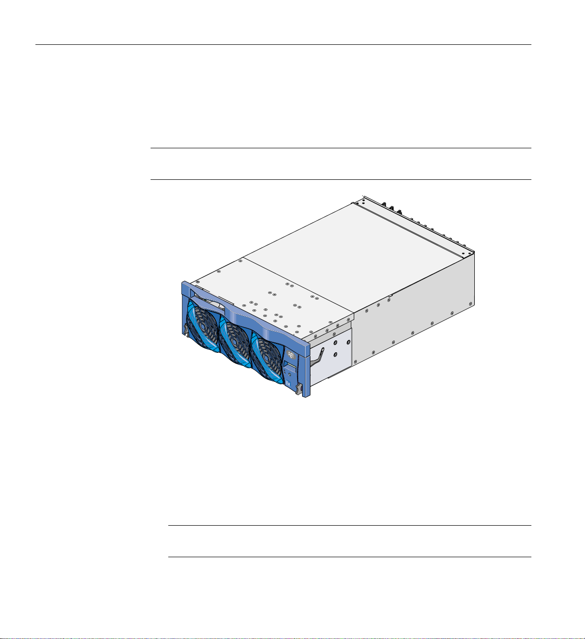
4: IX-brick
Product Overview
The 4U-high IX-brick, shown in Figure 4-1, provides 12 PCI-X slots that support up to 12
PCI or PCI-X cards. The 12 slots are configured as six 2-slot buses.
Note: You can install PCI cards in 11 of the 12 PCI slots. One slot (the leftmost slot) is
reserved for an IO9 PCI card. This card is required for the base I/O functions.
Figure 4-1 Front View of IX-brick
The IX-brick is the follow-on product of the I-brick. Compared to the I-brick, the IX-brick
offers the following enhancements:
• The IX-brick supports both PCI and PCI-X cards.
• The IX-brick can have two or four serial ports. The first two serial ports are standard
components of the IX-brick (similar to the I-brick). The third and fourth serial ports
reside on a daughtercard that you can purchase as an optional component.
Note: The serial-port daughtercard requires the space of one PCI-X slot, but it does
not connect to the PCI-X bus.
66 007-4653-001

Product Overview
Three PIC (PCI interface chip) ASICs are key components of the IX-brick architecture.
These ASICs support two 1200- or 800-MB/s Xtown2 XIO ports and six PCI-X buses (see
Figure 4-2). Each bus has two card slots in which you can install PCI cards. (Slot 1 of bus
1, however, seats the IO9 card.)
Bus 6 slot 2
Bus 6 slot 1
PIC
ASIC
Port F
Bus 5 slot 2
Port A
(XIO)
Port B
(XIO)
Port D (XIO)
Port D (XIO)
PIC
ASIC
Port C (XIO)
Port D (XIO)
PIC
ASIC
Port F
Port F
SCSI disk drives (2)
DVD-ROM
Bus 5 slot 1
Crosstown2 XIO port
Bus 4 slot 2
Bus 4 slot 1
Bus 3 slot 2
Bus 3 slot 1
Crosstown2 XIO port
Bus 2 slot 2
Bus 2 slot 1
Bus 1 slot 2
Bus 1 slot 1
IO9 PCI card
Ethernet port
SCSI port
RTI ports
Serial ports
Figure 4-2 IX-brick Block Diagram
007-4653-001 67

4: IX-brick
Also important to the IX-brick architecture is the IO9 PCI card. This card contains logic
that controls the DVD-ROM and internal SCSI disk drives, and it provides the following
connectors (see Figure 4-3):
• External VHDCI SCSI port connector.
• Internal SCSI port connector that connects to two SCSI disks.
• Gigabit Ethernet RJ45 connector.
• Two RT interrupt stereo jack connectors (one input connector labeled
RTI, and one
output connector labeled RTO).
• Two RS-232 DB-9 serial port connectors. (These two connectors are not located on
the IO9 PCI card; instead, they are located on the right side of the IX-brick rear
panel [see Figure 4-5 on page 73].)
• You can also add an optional daughtercard to the IO9 card that adds two additional
RS-232 DB-9 serial port connectors to the IX-brick.
68 007-4653-001

IO9 card
RS-232
RS-232
RS-232
RS-232
Ethernet 10MB/100MB/1G
SCSI 160MB/sec
DVD-ROM
SCSI
disk drives
IDE
interface
Internal
SCSI port
IOC4
FPGA
ASIC
Broadcom
BCM5701
ASIC
QLogic
ASIC
Figure 4-3 IO9 Card and Daughtercard Block Diagram
Standard
daughtercard
Optional
daughtercard
Product Overview
RS-232
Serial port
RS-232
Serial port
RS-232
Serial port
RS-232
Serial port
RT Interrupt
RT Interrupt
Ethernet port
SCSI port
007-4653-001 69

4: IX-brick
External Components
This section describes the external components that are located on the front and rear
panels of the IX-brick.
Front Panel Components
The IX-brick has the following front-panel components (see Figure 4-4):
• Two SCSI disk drives. These customer-removable, sled-mounted SCSI disk drives
are used to store your operating system and other application software. (See
“Installing or Replacing Disk Drives in IX-brick” on page 211) for instructions for
installing or removing the SCSI disk drives.
• DVD-ROM device. This device loads software onto your IX-brick. (It is used for
text reading only in CD-ROM mode.)
• L1 controller display. This liquid crystal display (LCD) displays status and error
messages that the L1 controller generates.
Note: For more information about the L1 controller, see the SGI L1 and L2 Controller
Software User’s Guide.
• On/Off switch with LED. Press this button to turn on the internal components of
the IX-brick. Alternatively, you can turn on the internal components at the L2
controller touch display or at a system console.
• LEDs:
– On/Off switch LED. This green LED illuminates when 48-VDC power is
applied to the internal components of the IX-brick.
– Service required LED. This LED illuminates yellow to indicate that a
component is broken or is not operating properly (for example, if a fan is off),
but the IX-brick is still operating.
– Failure LED. This LED illuminates red to indicate that a system failure has
occurred and the IX-brick is not operating.
• Fans. Three hot-swappable fans provide the required cooling for your IX-brick.
70 007-4653-001

Warning: To prevent personal injury, or damage to the IX-brick, the
hot-swappable fans can be installed only by a trained SGI system support
engineer (SSE).
SCSI disk
drives
DVD-ROM
Service required LED
Drive bay cover
External Components
Display
On/Off switch
with LED
Failure LED
Figure 4-4 Front Panel of IX-brick
007-4653-001 71

4: IX-brick
Rear Panel Components
The IX-brick has the following rear-panel components (see Figure 4-5):
• Power switch. Moving the power switch to the 1 position powers on the L1
• 12-VDC LED. The 12-VDC LED illuminates green when the L1 controller is
• 48-VDC LED. The power switch must be in the ON (1) position for this LED to
• PWR (power) connector. This connector connects to a power bay, which provides
• PCI-X slots. These slots seat the PCI cards. The card slots are numbered bus 1
• PCI-X slot LEDs. Each PCI-X slot has the following LEDs:
controller of the IX-brick, and moving it to the 0 position powers off the L1
controller.
powered on.
light. The 48-VDC LED illuminates green when the rest of the IX-brick internal
components are powered on.
power to the IX-brick.
through bus 6. Each bus has two slots, labeled 1 and 2, as shown in Figure 4-6.
– PWR (power) LED. This LED illuminates green when the PCI card is installed
securely and is getting power.
– Fault LED. This LED illuminates yellow when a fault occurs with the PCI card.
• XIO 10 and XIO 11 connectors. Each connector can connect the IX-brick to one IP53
node board. As an option, the second connector can connect to another IP53 node
board to create a dual-ported IX-brick, which provides greater bandwidth.
• XIO 10 and XIO 11 connector LEDs. Each XIO connector has two LEDs, as follows:
– The yellow LED illuminates to indicate that both the IX-brick and the IP53 node
board to which it is connected are powered on.
– The green LED illuminates when a link has been established between the
IX-brick and the IP53 node board to which it connects.
72 007-4653-001

External Components
The leftmost PCI-X slot (bus 1, slot 1) seats an IO9 card that has the following connectors:
• SCSI 68-pin VHDCI connector. This external SCSI port connects to SCSI devices.
• Ethernet RJ45 connector. This autonegotiating 10/100/1000BaseT Ethernet port
connects the system to an Ethernet network.
• RTO and RTI stereo jack connectors. RTO (output) enables a Cx-brick to interrupt
an external device. RTI (input) enables an external device to interrupt a Cx-brick.
The IO9 card also connects to a daughtercard (standard component) that has the
following connectors:
• Two DB-9 RS-232 serial port connectors. These ports can be used as COM ports to
connect to modems or other serial devices.
Note: An optional serial port daughtercard can be attached to your IO9 card by an SGI
system support engineer (SSE). This card adds two additional serial ports to the IX-brick.
One LED lights yellow,
the other lights green
XIO
Connectors
IO9 card
SCSI connector
Power switch
48/12VDC LEDs
Ethernet connector
RT0
RT1
48VDC
12VDC
PCI-X slot LEDs
XIO 10 XIO 11
Serial port
connector 1
Serial port
connector 0
Figure 4-5 Rear Panel of IX-brick
007-4653-001 73

4: IX-brick
PCI and PCI-X Card Configuration Guidelines
The PCI-X slots are numbered bus 1 through bus 6. Each bus has two slots, labeled 1 and
2, as shown in Figure 4-6. Separate buses enable the IX-brick to run cards of different
frequencies at the same time. For example, bus 1 can have one 133-MHz card, bus 2 can
have two 66-MHz cards, bus 3 can have two 33-MHz cards, and so on. Each PCI-X bus
supports 32-bit and 64-bit PCI or PCI-X cards at the same time.
For maximum bandwidth, PCI cards are distributed across all six buses when they are
integrated at the factory.
This section contains the following information:
• “Important Installation Considerations” on page 75
• “Supported PCI Cards” on page 75
• “PCI Card Carrier” on page 76
Bus 1 Bus 2
1 2
48VDC
12VDC
Slot
Slot
1 2
XIO 10 XIO 11
Bus 3 Bus 4
Slot
1 2
Slot
1 2
Figure 4-6 Numbering of IX-brick PCI-X Slots
Bus 5 Bus 6
Slot
1 2
Slot
1 2
74 007-4653-001
 Loading...