


Silicon Graphics® Octane2™ Duo
Installation Guide
007-4506-001

CONTRIBUTORS
Written by Eric Zamost
Illustrated by Dan Young
Production by Karen Jacobson
Contributions by Charles Alexander, Ben Drago, Matthew Humphries, Niaz Khan, and Jim Pagura
COPYRIGHT
© 2001 Silicon Graphics, Inc. All rights reserved; provided portions may be copyright in third parties, as indicated elsewhere herein. No
permission is granted to copy, distribute, or create derivative works from the contents of this electronic documentation in any manner, in whole
or in part, without the prior written permission of Silicon Graphics, Inc.
LIMITED RIGHTS LEGEND
The electronic (software) version of this document was developed at private expense; if acquired under an agreement with the USA government
or any contractor thereto, it is acquired as "commercial computer software" subject to the provisions of its applicable license agreement, as
specified in (a) 48 CFR 12.212 of the FAR; or, if acquired for Department of Defense units, (b) 48 CFR 227-7202 of the DoD FAR Supplement; or
sections succeeding thereto. Contractor/manufacturer is Silicon Graphics, Inc., 1600 Amphitheatre Parkway 2E, Mountain View, CA 94043-1351.
TRADEMARKS AND ATTRIBUTIONS
Silicon Graphics, IRIX, Octane, and OpenGL are registered trademarks and SGI, the SGI logo, IRIS GL, Octane2, XIO, and VPro are trademarks
of Silicon Graphics, Inc.
Envi-ro-tech and Techspray are trademarks of Techspray. Logitech is a registered trademark of Logitech. UNIX and the X device are registered
trademarks of the Open Group in the United States and other countries.
Cover Design By Sarah Bolles, Sarah Bolles Design, and Dany Galgani, SGI Technical Publications.

Record of Revision
Version Description
001 November 2001
Initial version
007-4506-001 iii


Contents
Figures . . . . . . . . . . . . . . . . . . . . . . . . . . ix
Tables . . . . . . . . . . . . . . . . . . . . . . . . . . xi
About This Guide. . . . . . . . . . . . . . . . . . . . . . .xiii
Related Publications . . . . . . . . . . . . . . . . . . . . . . xiv
Obtaining Publications . . . . . . . . . . . . . . . . . . . . . xiv
Conventions . . . . . . . . . . . . . . . . . . . . . . . . xiv
Reader Comments . . . . . . . . . . . . . . . . . . . . . . . xv
1. Octane2 Duo Overview . . . . . . . . . . . . . . . . . . . . . 1
Description of the Silicon Graphics Octane2 Duo Option. . . . . . . . . . . . 1
Octane2 Duo Upgrade Kit Contents. . . . . . . . . . . . . . . . . . 1
Octane2 Duo Upgrade System Requirements . . . . . . . . . . . . . . . 3
2. Duo Software Installation . . . . . . . . . . . . . . . . . . . . 5
Verifying Your IRIX Version . . . . . . . . . . . . . . . . . . . . 5
IRIX 6.5.13 or Earlier . . . . . . . . . . . . . . . . . . . . . 6
IRIX 6.5.14 . . . . . . . . . . . . . . . . . . . . . . . . 6
IRIX 6.5.15 or Later (When Available) . . . . . . . . . . . . . . . . 6
Performing a System Backup. . . . . . . . . . . . . . . . . . . . 6
Backing Up the Xserver File and Enabling Duo Software . . . . . . . . . . . 7
3. Octane2 Duo Upgrade Hardware Installation . . . . . . . . . . . . . . 9
Preparing the Workstation for the Upgrade . . . . . . . . . . . . . . . 9
Installing the Option Drive . . . . . . . . . . . . . . . . . . . . 10
Installing the Additional System Memory . . . . . . . . . . . . . . . . 11
Installing the PCI Module and PCI Card . . . . . . . . . . . . . . . . 13
Attaching the Regulatory Label . . . . . . . . . . . . . . . . . . . 15
007-4506-001 v

Contents
4. Connecting the Secondary Keyboard and Mouse. . . . . . . . . . . . . . 17
Connecting Cables to the System Module . . . . . . . . . . . . . . . . 17
Connecting Cables to the Graphics Boards . . . . . . . . . . . . . . . . 18
Connecting Cables to the PCI Module . . . . . . . . . . . . . . . . . 19
5. Configuring the System and Verifying Installation . . . . . . . . . . . . . 21
About the Option Drive . . . . . . . . . . . . . . . . . . . . . 22
Verifying an Internal Drive Installation . . . . . . . . . . . . . . . . . 22
Mounting the Second Drive . . . . . . . . . . . . . . . . . . . . 23
Adding Swap Space . . . . . . . . . . . . . . . . . . . . . . 24
Adding Users . . . . . . . . . . . . . . . . . . . . . . . . 26
Configuring Input Devices . . . . . . . . . . . . . . . . . . . . 28
Configuring a Serial Input Device for Head 1 . . . . . . . . . . . . . . 28
Configuring a Serial Input Device for Head 0 . . . . . . . . . . . . . . 29
Listing Serial Input Devices . . . . . . . . . . . . . . . . . . . 29
Verifying the Memory Installation . . . . . . . . . . . . . . . . . . 31
Verifying the PCI Card Installation . . . . . . . . . . . . . . . . . . 32
Selecting the Head on Which a Program Runs . . . . . . . . . . . . . . .33
Configuring a Duo System to Function as a Dual Head System . . . . . . . . . . 34
6. Using the Octane2 Duo System . . . . . . . . . . . . . . . . . . . 35
7. Troubleshooting the Duo Upgrade . . . . . . . . . . . . . . . . . . 39
Troubleshooting Tips . . . . . . . . . . . . . . . . . . . . . . 39
8. Removing the Duo Upgrade . . . . . . . . . . . . . . . . . . . . 41
Preparing the Workstation for the Removal. . . . . . . . . . . . . . . . 42
Removing the Option Drive . . . . . . . . . . . . . . . . . . . . 43
Removing the Additional System Memory . . . . . . . . . . . . . . . .44
Removing the PCI Module and PCI Card . . . . . . . . . . . . . . . . 46
A. Care and Cleaning of Compression Connectors . . . . . . . . . . . . . . 49
Guidelines for Storing and Handling Compression Connectors . . . . . . . . . . 50
Guidelines for Cleaning Compression Connectors . . . . . . . . . . . . . . 51
B. Choosing a Graphics Head (for Developers) . . . . . . . . . . . . . . . 55
Using Multiple Graphics Heads Under OpenGL, X, or Mixed-Model IRIS GL . . . . . . 55
vi 007-4506-001

Contents
Using Multiple Heads Under IRIS GL . . . . . . . . . . . . . . . . . 57
Specifying Screen Adjacency . . . . . . . . . . . . . . . . . . . . 57
C. Cabling and Configuring PCI Ethernet Boards . . . . . . . . . . . . . . 59
About the ioconfig.conf File. . . . . . . . . . . . . . . . . . . 59
Removing the ioconfig.conf File . . . . . . . . . . . . . . . . . 59
Mapping the Logical Controller Numbers to the Physical Port Locations . . . . . . . 60
Logical Controller Number Column . . . . . . . . . . . . . . . . 61
Hardware, Node, and Bus Type Columns . . . . . . . . . . . . . . . 61
Physical XIO Slot ID Column . . . . . . . . . . . . . . . . . . 62
Bus Type Column. . . . . . . . . . . . . . . . . . . . . . 63
Slot ID Column . . . . . . . . . . . . . . . . . . . . . . 64
Port Type Column . . . . . . . . . . . . . . . . . . . . . 65
Serial Port ID Column . . . . . . . . . . . . . . . . . . . . 65
After Installing the Board and Cables . . . . . . . . . . . . . . . . . 66
Index . . . . . . . . . . . . . . . . . . . . . . . . . . 67
007-4506-001 vii


Figures
Figure 1-1 Octane2 Duo Upgrade Kit Contents . . . . . . . . . . 2
Figure 3-1 Locating the System Label. . . . . . . . . . . . . 15
Figure 4-1 Connecting the Keyboard and Mouse Cables to the PCI Card . . 19
Figure A-1 Identifying the Bristled Pad of the Compression Connector . . . 49
Figure A-2 Spraying the Compression Connector . . . . . . . . . 52
Figure C-1 Physical XIO Identification Numbers and Software Designations . 62
Figure C-2 PCI Module Slot Numbers . . . . . . . . . . . . 64
007-4506-001 ix


Tables
Table 5-1 Serial Devices and Their Modular Names . . . . . . . . 30
Table 6-1 Tasks with Duo-Specific Instructions . . . . . . . . . 36
Table 7-1 Troubleshooting Tips . . . . . . . . . . . . . . 39
Table C-1 Identification of Information in the ioconfig.conf File . . . 60
Table C-2 XIO Slot ID Mapping . . . . . . . . . . . . . . 63
Table C-3 Port Type Abbreviations and Definitions . . . . . . . . 65
Table C-4 Determining Which Boards to Configure . . . . . . . . 66
007-4506-001 xi


About This Guide
This guide describes the installation, use, troubleshooting, and removal of the Duo
upgrade in an Octane2 workstation.
The Octane2 Duo upgrade allows a single Octane2 workstation to be simultaneously
used by two people.
The guide is organized as follows:
• This section provides additional hardware information, software and system
administration information, and product support information.
• Chapter 1 provides an overview of the Octane2 Duo option, describes the kit
contents, and lists the requirements for a system to be upgradable.
• Chapter 2 provides information about installing the software for the Duo upgrade.
• Chapter 3 provides information about installing the hardware for the Duo upgrade.
• Chapter 4 provides information about connecting the secondary keyboard and
mouse.
• Chapter 5 provides information about configuring the system and verifying the
installation.
• Chapter 6 provides information about using the Duo system.
• Chapter 7 provides troubleshooting information.
• Chapter 8 provides information about removing the Duo upgrade.
• Appendix A provides information about the care and cleaning of the compression
connectors.
• Appendix B provides information about choosing a graphics head (for software
developers).
• Appendix C provides information about cabling and configuring the PCI Ethernet
card.
• An Index completes this guide.
007-4506-001 xiii

About This Guide
Related Publications
The following documents contain additional information that may be helpful:
• Octane2 Workstation Owner's Guide
• Silicon Graphics Octane2 Dual Head Installation Guide
• Silicon Graphics Octane2 Workstation Dual Channel Display Installation Guide
• Personal System Administration Guide
Obtaining Publications
To obtain SGI documentation, go to the SGI Technical Publications Library at:
http://techpubs.sgi.com
Conventions
The following conventions are used throughout this document:
Convention Meaning
command This fixed-space font denotes literal items such as commands, files,
routines, path names,signals, messages, andprogramming language
structures.
variable Italic typeface denotes variable entries and words or concepts being
defined.
user input This bold, fixed-space font denotes literal items that the user enters
in interactive sessions. Output is shown in nonbold, fixed-space font.
[] Brackets enclose optional portions of a command or directive line.
... Ellipses indicate that a preceding element can be repeated.
GUI This font denotes the names of graphical user interface (GUI)
elements such as windows, screens, dialog boxes, menus, toolbars,
icons, buttons, boxes, fields, and lists
xiv 007-4506-001

Reader Comments
About This Guide
If you have comments about the technical accuracy, content, or organization of this
document, please tell us. Be sure to include thetitle anddocument numberof the manual
with your comments. (Online, the document number is located in the front matter of the
manual. In printed manuals, the document number is located at the bottom of each
page.)
You can contact us in any of the following ways:
• Send e-mail to the following address:
techpubs@sgi.com
• Use the Feedback option on the Technical Publications Library World Wide Web
page:
http://techpubs.sgi.com
• Contact your customer service representative and ask that an incident be filed in the
SGI incident tracking system.
• Send mail to the following address:
Technical Publications
SGI
1600 Ampitheatre Parkway, M/S 535
Mountain View, California 94043-1351
• Send a fax to the attention of “Technical Publications” at +1 650 932 0801.
We value your comments and will respond to them promptly.
007-4506-001 xv


Chapter 1
1. Octane2 Duo Overview
This chapter provides an overview of the Silicon Graphics Octane2 Duo option.
Description of the Silicon Graphics Octane2 Duo Option
The Silicon Graphics Octane2 Duo option allows the connection of a second keyboard
and a second mouse to an Octane2 workstation, thus allowing a Dual Head Octane2
workstation to be simultaneously used by two people.
In addition to adding connections for the keyboard and mouse, the upgrade kit also adds
more main memory and an additional hard disk drive.
Octane2 Duo Upgrade Kit Contents
The Octane2 Duo upgrade kit contains the following items (illustrated in Figure 1-1):
• The Silicon Graphics Octane2 Duo Installation Guide (this manual)
• Screwdriver
• Disposable wrist strap
• PCI module (PCI card cage)
• PCI card (with ports for keyboard, mouse, and Ethernet)
• Keyboard
• Mouse
• 24 foot (7.3 meter) extension cable for keyboard and mouse
• Additional system memory
• Additional internal hard disk drive (“option drive”)
007-4506-001 1

1: Octane2 Duo Overview
Documentation
Cap on
compression
connector
PCI Module
Reversible
screwdriver
PCI card
Wriststrap
Keyboard
Mouse
24 ft. (7.3m) extension cable
for keyboard and mouse
Memory
Figure 1-1 Octane2 Duo Upgrade Kit Contents
2 007-4506-001
Option drive

Octane2 Duo Upgrade System Requirements
To install the Octane2 Duo upgrade, your Silicon Graphics Octane2 workstation must
meet the following minimum requirements:
• It must have an Octane2 Dual Head VPro graphics option installed and fully
functional
• It must have at least two monitors (one on each graphics head)
• In must have two CPUs
• It must have IRIX version 6.5.14 installed with patch 4426, or any later version of
IRIX
Octane2 Duo Upgrade System Requirements
007-4506-001 3


Chapter 2
2. Duo Software Installation
You should install the software for your Silicon Graphics Octane2 Duo upgrade before
you install the hardware. After the software and hardware are installed, Chapter 5
provides system setup and verification instructions.
The software installation process for the Duo upgrade consists of the following steps:
• Verifying your IRIX version
• Performing a system backup
• Backing up the Xserver file and enabling the Duo software
Note: Read any release notes included with your upgrade kit before installing the
software to learn of any last minute changes.
Verifying Your IRIX Version
To verify the version of the IRIX operating system installed on your Octane2 system,
follow the instructions in this section.
From an IRIX command prompt, type:
1% uname -R
You will see output similar to the following:
6.5 6.5.13f
Depending on your version, go to one of these sections: “IRIX 6.5.13 or Earlier,” “IRIX
6.5.14,” or “IRIX 6.5.15 or Later (When Available).”
007-4506-001 5

2: Duo Software Installation
IRIX 6.5.13 or Earlier
IRIX 6.5.14
If you system has IRIX version 6.5.13 or earlier, you will need to upgrade your system to
IRIX 6.5.14 with patch 4426, or IRIX 6.5.15 (when available), before installing the Duo
hardware. Contact your SGI representative for more information.
If you system has IRIX version 6.5.14, you will need patch 4426 before installing the Duo
hardware.
To determine if you have patch 4426 installed, type the following at an IRIX command
prompt:
2% versions patchSG0004426
If the output of this command is simply the headings “Name,” “Date,” and
“Description” you do not have patch 4426 installed. This patch must be installed (or you
must upgrade your system to IRIX 6.5.15 or later, when released) before installing the
Duo hardware.
If the output of this command includes items below the Name-Date-Description
heading, you do have patch 4426 installed, and you may install the Duo hardware.
IRIX 6.5.15 or Later (When Available)
If your system has IRIX version 6.5.15 or later (when available), you may install the Duo
hardware.
Performing a System Backup
It is always a good idea to back up your system before installing any new hardware. If
you have not backed up your system recently, take this opportunity to do so. For
instructions on backing up your system, see the Personal System Administration Guide.
6 007-4506-001

Backing Up the Xserver File and Enabling Duo Software
Backing Up the Xserver File and Enabling Duo Software
After ensuring that you are running an appropriate version of IRIX, you must back up
the original Xserver file, enable the Duo software by installing a new Xserver file, and
replace the default login screen.
Follow these instructions:
1. From Toolchest > Desktop, select Open UNIX Shell.
2. Become superuser by typing su.
3. At the prompt, type:
cp /var/X11/xdm/Xserver /var/X11/xdm/Xserver.orig
4. At the prompt, type:
cp /var/X11/xdm/Xserver.2key /var/X11/xdm/Xserver
5. At the prompt, type:
chkconfig visuallogin off
6. Type exit to exit superuser mode.
7. Restart the system. The new login screen appears.
Proceed to Chapter 3, “Octane2 Duo Upgrade Hardware Installation” to begin installing
the hardware.
007-4506-001 7


Chapter 3
3. Octane2 Duo Upgrade Hardware Installation
This chapter describes the installation of the hardware portion of the Silicon Graphics
Octane2 Duo upgrade.
The upgrade consists of the following sections:
• “Preparing the Workstation for the Upgrade” on page 9
• “Installing the Option Drive” on page 10
• “Installing the Additional System Memory” on page 11
• “Installing the PCI Module and PCI Card” on page 13
• “Attaching the Regulatory Label” on page 15
This chapter relies heavily on your Octane2 Workstation Owner’s Guide. Make sure you
have it handy before proceeding with the upgrade.
Preparing the Workstation for the Upgrade
Before installing any new hardware in your workstation, you should first perform a
complete backup of your system.
After making a backup you should shut down the operating system and power off the
workstation.
The memory, PCI module, and PCI card upgrades require the use of the static dissipating
wrist strap that came with your upgrade kit.
007-4506-001 9

3: Octane2 Duo Upgrade Hardware Installation
Installing the Option Drive
The Octane2 Duo upgrade includes an additional internal hard disk drive (“option
drive”) for your Octane2. This provides the additional storage required in order for two
people to simultaneously use the system.
The instructions for installing the internal drive may be found in Chapter 7, “Installing
and Removing Internal Drives and Front Module Parts,” in your Octane2 Workstation
Owner’s Guide. The steps involved in the process are outlined below, along with
references to specific portions of Chapter 7 in your Octane2 Workstation Owner’s Guide.
To install the option drive, follow these steps:
1. Shut down and power off your workstation, as described on page 161 of your
Octane2 Workstation Owner’s Guide.
2. Remove the lock bar and the front bezel from your workstation, as described on
pages 162 through 164 of your Octane2 Workstation Owner’s Guide.
3. Install the internal drive into one of the empty drive bays (either the middle bay or
the upper bay), as described on pages 165 through 167 of your Octane2 Workstation
Owner’s Guide.
Note: The lower bay is used for the system drive, and will already be occupied.
4. Remove the appropriate blank panel (that is, the middle or upper one) from the
front bezel, as described on pages 168 and 169 of your Octane2 Workstation Owner’s
Guide. Save the blank panel for reinstallation in case you later remove the internal
drive.
5. Reinstall the front bezel and the lock bar, as described on pages 195 and 196 of your
Octane2 Workstation Owner’s Guide.
6. Power on your workstation, as described on page 197 of your Octane2 Workstation
Owner’s Guide.
7. Test the new internal option drive, as described on page 176 of your Octane2
Workstation Owner’s Guide.
Your additional hard disk drive is now installed.
10 007-4506-001

Installing the Additional System Memory
The Octane2 Duo upgrade includes additional system memory (RAM) for your Octane2.
This provides the additional main memory required when two people are
simultaneously using the Octane2 system.
The instructions for installing additional memory may be found in Chapter 2, “Installing
and Removing the CPU and Memory,” in your Octane2 Workstation Owner’s Guide. The
steps involved in the process are outlined below, along with references to specific
portions of Chapter 2 in your Octane2 Workstation Owner’s Guide.
To install the additional memory, follow these steps:
1. Shut down and power off your workstation, as described on page 32 of your
Octane2 Workstation Owner’s Guide.
2. Remove the lock bar from your workstation, as described on page 33 of your
Octane2 Workstation Owner’s Guide.
3. Remove the cables from your workstation system module, as described on page 34
of your Octane2 Workstation Owner’s Guide.
Installing the Additional System Memory
Note: Make a note of the location of each of the cables in order to facilitate their
reconnection.
4. Attach a wrist strap to your wrist and to a ground, as described on page 35 of your
Octane2 Workstation Owner’s Guide.
Caution: The components inside your workstation are extremely sensitive to static
electricity. Always wear a wrist strap when you replace parts inside your
workstation.
5. Remove the system module, as described on pages 36 through 40 of your Octane2
Workstation Owner’s Guide.
Caution: Be sure to place a cap over each of the two compression connectors on the
system module, as described on page 40 of your Octane2 Workstation Owner’s Guide.
For more information about compression connectors, refer to Appendix A, “Care
and Cleaning of Compression Connectors”, in this manual.
007-4506-001 11

3: Octane2 Duo Upgrade Hardware Installation
6. Install the additional memory into the system module, as described on pages 47
through 52 of your Octane2 Workstation Owner’s Guide.
7. Reinstall the system module into the workstation, as described on pages 53 through
56 of your Octane2 Workstation Owner’s Guide.
8. Reconnect the cables to the system module, as described on page 57 of your Octane2
Workstation Owner’s Guide.
9. Reinstall the lock bar, as described on page 59 of your Octane2 Workstation Owner’s
Guide.
10. Power on your workstation, as described on page 58 of your Octane2 Workstation
Owner’s Guide.
11. Verify the new memory, as described on page 60 of your Octane2 Workstation
Owner’s Guide.
Your additional system memory is now installed.
12 007-4506-001

Installing the PCI Module and PCI Card
The Octane2 normally has ports to connect one keyboard and one mouse. In order to
support an additional keyboard and an additional mouse, the Duo upgrade includes a
PCI card that has an additional keyboard port and an additional mouse port. This card
also includes an additional Ethernet port.
In order to accept a PCI card, the Octane2 requires a special PCI card cage (also called the
PCI module), which is included with the Octane2 Duo upgrade.
The instructions for installing the PCI card and PCI module may be found in Chapter 4,
“Installing and Removing PCI Boards,” in your Octane2 Workstation Owner’s Guide. The
steps involved in the process are outlined below, along with references to specific
portions of Chapter 4 in your Octane2 Workstation Owner’s Guide.
To install the PCI card and PCI module, follow these steps:
1. Shut down and power off your workstation, as described on page 72 of your
Octane2 Workstation Owner’s Guide.
2. Attach a wrist strap to your wrist and to a ground, as described on page 74 of your
Octane2 Workstation Owner’s Guide.
Installing the PCI Module and PCI Card
Caution: The components inside your workstation are extremely sensitive to static
electricity. Always wear a wrist strap when you replace parts inside your
workstation.
3. Open the PCI module, as described on page 78 of your Octane2 Workstation Owner’s
Guide.
4. Select a slot for the PCI board. Unless you intend to use slot 1 for some other
purpose, use slot 1 for the Duo PCI board. For slot location information, see page 79
of your Octane2 Workstation Owner’s Guide.
5. Install the PCI board into the PCI module, as described on pages 80 through 83 of
your Octane2 Workstation Owner’s Guide.
6. Install the PCI module into the workstation, as described on pages 100 through 103
of your Octane2 Workstation Owner’s Guide.
007-4506-001 13

3: Octane2 Duo Upgrade Hardware Installation
Note: Save the PCI blanking plate, as it will be required in case you ever decide to
remove the PCI module.
Note: Installation of the keyboard and mouse cables are covered in this book, in
Chapter 4, “Connecting the Secondary Keyboard and Mouse”.
7. Power on your workstation, as described on page 104 of your Octane2 Workstation
Owner’s Guide.
8. Verify the PCI module and PCI card installation, as described in “Verifying the PCI
Card Installation” on page 32 of this book.
Your PCI card and PCI module are now installed.
14 007-4506-001

Attaching the Regulatory Label
If you received a system upgrade label with your Duo kit, place it on the Octane2 system
label, as follows:
1. Face the back of the Octane2 workstation. The system label (containing the model
number/CMN number) is located at the top center of the back of the workstation,
as shown in Figure 3-1.
2. Place the upgrade label over the VCCI and CISPR 22 information.
Attaching the Regulatory Label
RL
In Out
2
1
System label
Figure 3-1 Locating the System Label
Proceed to Chapter 4 to connect the second keyboard and mouse.
007-4506-001 15


Chapter 4
4. Connecting the Secondary Keyboard and Mouse
This chapter describes the connection of the second keyboard and mouse to the newly
installed keyboard and mouse ports on the Duo PCI card in your Silicon Graphics
Octane2 workstation.
Connecting Cables to the System Module
If you have not already reconnected all the cables you removed from the system module,
do so now. These will typically include sound cables, Ethernet cable, and the primary
keyboard and mouse cables.
Note: The keyboard and mouse ports on the system module are interchangeable. Either
port will work for either device. However, you must connect both devices while the
system is powered off.
For a detailed explanation of the ports and cable connections on your Octane2
workstation, refer to your Octane2 Workstation Owner’s Guide.
007-4506-001 17

4: Connecting the Secondary Keyboard and Mouse
Connecting Cables to the Graphics Boards
If the monitor cables are not connected, connect them now.
In a typical Dual Head system (that is, one with no display option boards), the upper
connector is for the primary head and the lower connector is for the secondary head.
For more information about connecting monitors to Dual Head systems with no display
option boards, see the Silicon Graphics Octane2 Dual Head Installation Guide. Refer to
“Obtaining Publications” on page xiv for instructions about how to access this
document.
If the system has a single display option board (also called a dual channel board)
installed, the upper two DVI connectors are for the two monitors on the primary head.
If the system has two display option boards installed, the lower two DVI connectors are
for the two monitors on the secondary head.
For more information about connecting monitors to systems with display option
board(s), see the Silicon Graphics Octane2 Workstation Display Option Board Installation
Guide. Refer to “Obtaining Publications” on page xiv for instructions about how to access
this document.
18 007-4506-001

Connecting Cables to the PCI Module
Connect the new keyboard and mouse as follows:
1. Connect the keyboard and mouse extension cables to the keyboard and mouse ports
on the PCI card (see Figure 4-1).
Connecting Cables to the PCI Module
L
R
Keyboard
Mouse
Figure 4-1 Connecting the Keyboard and Mouse Cables to the PCI Card
007-4506-001 19

4: Connecting the Secondary Keyboard and Mouse
Note: Unlike the keyboard and mouse ports on the system module, the ports on the
PCI card are not interchangeable. Be sure to plug the keyboard cable into the
keyboard port (toward the left), and the mouse cable into the mouse port (toward the
right).
Tip: When plugging the keyboard and mouse cables into the ports on the PCI board,
push them in firmly, as they may be a tight fit.
2. Connect the other ends of the keyboard and mouse extension cables to the keyboard
and mouse at the secondary user locations.
Proceed to Chapter 5 to configure the system and verify the installation.
20 007-4506-001

Chapter 5
5. Configuring the System and Verifying Installation
This chapter describes how to install the software needed for the Duo configuration and
provides information on system setup and verifying various hardware installations.
The information in this chapter includes:
• “About the Option Drive” on page 22.
• “Verifying an Internal Drive Installation” on page 22.
• “Mounting the Second Drive” on page 23.
• “Adding Swap Space” on page 24.
• “Adding Users” on page 26.
• “Configuring Input Devices” on page 28.
• “Verifying the Memory Installation” on page 31.
• “Verifying the PCI Card Installation” on page 32.
• “Selecting the Head on Which a Program Runs” on page 33.
• “Configuring a Duo System to Function as a Dual Head System” on page 34.
007-4506-001 21

5: Configuring the System and Verifying Installation
About the Option Drive
Internal SCSI devices (drives) are automatically given an address whenthey are inserted.
Bus 0 (which contains the internal devices) has addresses such as 0-1, 0-2, 0-3.The system
drive (the lower drive) is SCSI ID 0-1 (bus0, device1), the option drive above it (the center
drive) is SCSI ID 0-2 (bus 0, device 2), and the option drive at the top of the workstation
is SCSI ID 0-3 (bus 0, device 3).
Tip: To determine the total capacity and remaining space available on your disks, go to
Toolchest > System > File System Manager and click the Get Info button.
Verifying an Internal Drive Installation
The workstation automatically sets up the system software for most internal devices you
install and places an icon on the desktop.
Once you install the drive, follow these steps to check that the system recognizes the new
drive.
1. Log in to the root account. For more information on logging in, refer to the Octane2
Workstation Owner’s Guide, “Logging In to the Octane2 Workstation,” on page 21.
2. If the device is installed correctly, you will see an icon for it on the desktop.
Double-click the icon to mount the drive.
3. You can also use the System Manager to check that the drive is shown correctly.
a. Go to Toolchest > System > System Manager > Hardware and Devices > Disk
Manager. You will see a list of installed disk drives.
b. Select the drive, and click the Get Info button.
Sometimes the Desktop does not display the icon. If the drive you installed does not
appear on the Desktop, try opening a UNIX shell and typing hinv. If the drive does not
appear tobe installed,power off the system and make sure the drive is completely seated
in the slot. Then restart the system and check the System Manager listing again.
22 007-4506-001

Mounting the Second Drive
For the second drive to be usable, it needs to be mounted. To mount the drive, follow
these steps:
1. Log in to the system as root.
2. Go to Toolchest > System > System Manager > Hardware and Devices > Disk
Manager. You will see a list of installed disk drives.
3. Select the drive you wish to mount, and click the Mount button.
4. Select a file system to mount (the default choice will usually be correct).
5. Click Next.
6. In the window that appears, type a mount point. For example, /disk2.
7. Click Next.
8. Check the box that says Let local users change filesystem contents.
9. Click Next.
10. Check the box that says Mount every time the system starts.
Mounting the Second Drive
11. Click Next.
12. Double check the settings, and, if they look correct, click OK.
Tip: The settings will include one that says Contents of existing directory will be
hidden. This refers to the contents of the directory on which the drive is being
mounted (/disk2, for example), and should be fine.
13. Click OK to close the window that reports successful completion.
14. Click Close to close the Disk Manager window.
15. Select File > Exit to exit the System Manager window.
The disk is now mounted.
007-4506-001 23

5: Configuring the System and Verifying Installation
Adding Swap Space
The following procedure is a recommendation for creating a swap file on the second
drive. Create more swap space only if you believe the swap space on the system disk is
insufficient and you know how much more swap space you want to add.
Note: The swap space on the system disk must have a different priority number than the
swap space on the second (option) disk.
To set up additional swap space,determine the amount of swapspace on the system disk,
and use that as a guideline to determine how much swap space to add.
1. Log in to the system as root.
2. Go to Toolchest > System > System Manager > System Performance > Swap
Manager.
3. When the Swap Manager window appears, note the amount of swap space
currently configured on the system disk (this information will be shown in the
Physical column).
4. Click Add.
5. Click Next.
The Add Real Swap Space dialog box appears. (Read all the information in every
dialog box.)
6. Type in your chosen amount of swap space. You may enter the same amount that
was on the system disk (typically 128 MB) or you can enter a different value.
7. Select the filesystem that represents the disk to which you have chosen to add the
swap file, for example, /dev/dsk/sks0d3s7.
Note: At this point you can choose to add additional swap space to either disk.
8. Click Next.
9. Click OK to confirm your settings.
10. Click OK to acknowledge completion.
11. Click Close to close the Swap Manager window.
24 007-4506-001

Adding Swap Space
You are finished adding swap space.
For additional information on adding swap space, go to Toolchest > Help > Online
Books > SGI Admin. See IRIX Admin: System Configuration and Operation (refer to
Chapter 6, “Configuring Disk and Swap Space”) and IRIX Admin: Disks and Filesystems.
007-4506-001 25

5: Configuring the System and Verifying Installation
Adding Users
It is recommended that you place all user accounts on the second (option) disk.
To add an additional user, follow these instructions:
1. Log in to the system as root.
2. Go to Toolchest > System > System Manager > Security and Access Control.
3. Click the Add a User Account icon.
The dialog box appears. Read the information in this and every dialog box before
proceeding.
4. Click Next.
5. Type a username for the new user.
6. Click Next.
7. Type the new user’s full name.
8. Click Next.
9. Press Next to accept the Local Account default.
10. Choose one of the Password options.
11. Click Next.
12. If you chose to add a password, enter it now (in both boxes), then click Next.
13. To accept the unique, automatically generated User ID (number), click Next.
14. To accept the default Primary Group for the new user, click Next.
15. In the Home Directory window, remove the default /usr/people/username
directory.
Because it is recommended that you place all users on the second (option) disk,
rather than the system disk, replace the default /usr/people/username
directory with the home directory of the new user on the option disk.
To do this, type the path to a location on the disk to which you wish to add the new
user. For example, /disk2/username.
16. Select Verify and create as needed.
17. Click Next.
26 007-4506-001

18. To accept the default shell program, csh, click Next.
19. Confirm that the settings are correct, and click OK.
You are finished adding the new user.
Adding Users
007-4506-001 27

5: Configuring the System and Verifying Installation
Configuring Input Devices
The IRIX operating system includes support for a number of input devices. Support for
additional devices can be added; see the input man page for details. This man page also
contains the most current listing of supported devices.
1. Choose the serial port (1 or 2) to which you will connect the serial device for head 1.
Tip: Configurethe serial device for head 1 (the secondary head) first. Then configure
the serial device for head 0 (the primary head).
2. Use head 0 (the primary head) to do the configuration. (All system administration
tasks should be done from head 0.)
Configuring a Serial Input Device for Head 1
1. Log in to the system on head 0 as root.
2. Go to Toolchest > System > System Manager > Hardware and Devices > Serial
Device Manager. Click the Add Other button.
3. Continue the installation by reading all the information in each dialog box that
appears and following the on-screen directions.
When you are done, you will have configured the device to head 0. The steps that
follow reconfigure the device to head 1.
4. Check Table 5-1 on page 30 for the module name of the serial device you have
configured.
5. From Toolchest > Desktop choose Open UNIX Shell.
6. At the prompt, type:
mv /dev/input/<module name> /dev/input1/<module name>
Example: mv /dev/input/sball /dev/input1/sball.
In this example, /input/ refers to head 0, /input1/ refers to head 1, and sball
to Spaceball.
7. Log out, and log in on the head for which the device was configured.
You are finished configuring a serial device to head 1.
28 007-4506-001

Configuring a Serial Input Device for Head 0
1. Log in to the system on head 0 as root.
2. Go to Toolchest > System > System Manager > Hardware and Devices > Serial
Device Manager. Click the Add Other button.
3. Continue the installation by reading all the information in each dialog box that
appears and following the on-screen directions.
When you are done, you will have configured the device to head 0.
4. Log out, and log in on head 0.
You are finished configuring a serial device to head 0.
Listing Serial Input Devices
To get a list of the devices configured to head 0 or head 1, follow these steps:
1. From Toolchest > Desktop, select Open UNIX Shell.
Configuring Input Devices
2. For devices configured for head 0 (the primary head) at the prompt type:
cd /dev/input/
For devices configured for head 1 (the secondary head) at the prompt type:
cd /dev/input1/
3. At the prompt type ls -l .
You will see something like:
keyboard -> /hw/input/keyboard
mouse -> /hw/input/mouse
sball -> /hw/ttys/ttyd1
Sball is the module name for Spaceball, in this example supported on head 0 (since this
was the listing for /dev/input/) and connected to serial port 1 (ttyd1).
007-4506-001 29

5: Configuring the System and Verifying Installation
See Table 5-1 for the module names of supported serial devices. See the inputman page
for the most current listing of supported devices.
Table 5-1 Serial Devices and Their Modular Names
Device Module Name
Calcomp tablet tablet
Hitachi HDG-J tablets hitachi
Other Hitachi tablets tablet
Wacom tablets wacom
Dial box dialbox
Button box dial
Dial and button box combination dial
Imp infra-red presentation mouse imp
Logitech Magellan 3D controller magellan
Spaceball sball
30 007-4506-001

Verifying the Memory Installation
1. Go to Toolchest > System > System Manager > About This System and check the
amount of memory listed after the Main Memory heading.
The amount of memory shown should be the total of the memory that was already
in the system and the additional amount you installed. For example, if the system
originally had 512 MB, and you installed two 512 MB DIMMs, the System Manager
should show that you now have 1536 MB of memory.
2. If the amount of memory is incorrect, follow the directions in “Installing the
Additional System Memory” on page 11 to power off your system and remove the
system module. Then check the installation as follows:
a. Check the angle of the DIMMs. They should be upright and completely seated.
b. Check that each bank is populated with two DIMMs and that they are the same
type. You must have an even number of DIMMs installed.
c. Check the color of the label on each DIMM. Both DIMMs in a bank must be of
the same size and type and must have the same colored label.
d. Continue following the directions on page 11 until the system module is
reinstalled and the system is powered back on.
Verifying the Memory Installation
3. After you have powered on the Octane2 workstation, check the amount of memory
again, as described in step 1. If the amount is still incorrect, see Chapter 7,
“Troubleshooting the Duo Upgrade.”
007-4506-001 31

5: Configuring the System and Verifying Installation
Verifying the PCI Card Installation
You can verify your PCI card installation by using the hinv command.
To verify that your PCI card is recognized, follow these instructions:
1. From Toolchest > Desktop select Open UNIX Shell.
2. At the prompt, type hinv.
3. In the hardware inventory that follows, look for two lines similar to the following:
Integral Fast Ethernet: ef0, version 1
Integral Fast Ethernet: ef1, version 1
The first line tells you that the Ethernet port on the system module is recognized. It
is designated ef0. The second line gives you confirmation that the PCI card
(containing the second Ethernet, keyboard, and mouse ports) is recognized. This is
the ef1 designation.
See Chapter 7, “Troubleshooting the Duo Upgrade,” if your Duo system is not operating
properly.
32 007-4506-001

Selecting the Head on Which a Program Runs
During an interactive session with the Window Manager, you can use the DISPLAY
environment variable to control the head on which newly started graphics programs run.
When DISPLAY is set to :0.0, programs you start run on head 0 (the primary head);
when it is set to :1.0, programs you start run on head 1 (the secondary head).
For convenience, the default startup files (.login, .profile) for root and guest
shells set DISPLAY to a reasonable initial value, if it is not already set. Each head has a
toolchest that can be used to invoke graphics programs. Each toolchest has the DISPLAY
variable in its environment set to the correct value for the head on which it appears, so
any application you invoke from a toolchest inherits this DISPLAY value, and thus
appears on the same head as the toolchest from which it was invoked.
Similarly, programs started by clicking an icon appear on the head from which you
invoked them.
Once a program has been launched, it is not possible to move it from one head to another
from the Window Manager.
Selecting the Head on Which a Program Runs
For more information on this topic, refer to Chapter 6, “Using the Octane2 Duo System,”
and read the information about using Duo. Also see Appendix B, “Choosing a Graphics
Head (for Developers)”.
007-4506-001 33

5: Configuring the System and Verifying Installation
Configuring a Duo System to Function as a Dual Head System
To configure your Duo system to function as a Dual Head system (that is, for both
monitors to be used simultaneously by one person), follow these instructions:
1. Log in to the system on head 0 as root.
2. From Toolchest > Desktop, select Open a UNIX Shell.
3. At the prompt, type:
cp /var/x11/xdm/Xserver.orig /var/x11/xdm/Xserver
4. Shut down the system.
5. Unplug the second keyboard and mouse.
6. Restart the system.
7. Refer to the Dual Head Installation Guide for information about the Dual Head
system. To access the online Technical Publications Library, open your Web browser
and enter http://techpubs.sgi.com/.
Proceed to Chapter 6 for information on using the Octane2 Duo system.
34 007-4506-001

Chapter 6
6. Using the Octane2 Duo System
This chapter provides information about using the Duo system. The Octane2
workstation was designed for a single user. This chapter helps you become aware of
some of the idiosyncrasies that arise when two people use the Octane2 workstation
simultaneously, and provides you with instructions for specific tasks.
Be sure you have read the README file on the Duo CD that directs you to the location of
the release notes. The release notes, in turn, direct you to the correct software and
patches, and any other information you may need to know before using the Duo system.
When using the Duo system, keep this information in mind:
• Simultaneous use of head 0 and head 1 by users in the same login account is not
supported.
• System start up, shut down, and warning messages appear only on the primary
head, as does the System Maintenance Menu.
• When using the Toolchest > Find menu, do not use File QuickFind or Host
QuickFind, as these appear simultaneously on both the primary and secondary
heads. Instead, use Toolchest > Find > Search For Files.
• If a System Administration tool launched from the desktop does not complete a
function, despite being supplied with the root password, the same application may
currently be running under a second account on the Duo system.
007-4506-001 35

6: Using the Octane2 Duo System
Table 6-1 lists more tasks with Duo-specific instructions.
Table 6-1 Tasks with Duo-Specific Instructions
Task Instruction
Determine the head on
which you are running
System administration
tasks
Logging in to a remote
system from the
secondary head (head 1)
From Toolchest > Desktop select Open UNIX Shell.
At the prompt, type printenv DISPLAY.
Look for the listing DISPLAY = 0.0 or DISPLAY = 1.0 .
Head 0 is the primary head.
Head 1 is the secondary head.
Use head 0.
In head 1 Toolchest > Desktop select Open UNIX Shell
Log in to the remote system. Type:
rlogin guest@
At the prompt, type: setenv DISPLAY localhost:1
(where
The remotely displayed information from the remote host will now
display to the secondary head (head 1). Without entering this
command, the remotely displayed information would display to the
primary head (head 0).
When using rsh, use:
rsh user@
(where
This command causes the output to appear on head 1.
localhost is the name of your Octane2 system).
localhost is the name of your Octane2 system).
remotehost
remotehost -display localhost:1
Using an icon to launch
an application
Changing a monitor
setting
36 007-4506-001
To run an application on a remote host and display it on head 1, use:
rsh remotehost
(where
localhost is the name of your Octane2 system and
applicationname -display localhost:1
applicationname is the application you are running).
Launch the application from the head you want to use. The icon
always appears on the head from which it was launched.
After changing the setting, always log out and then log back in.

Table 6-1 (continued) Tasks with Duo-Specific Instructions
Task Instruction
Hot plugging a mouse,
keyboard, Spaceball, etc.
Hot plugging any serial device is not supported. (Hot plugging is
attaching a device while the system is powered on.)
Configuring ef0and ef1 ef0 and ef1 cannot be configured with the same hostname and IP
address even though both interfaces are on the same system.
Using audio when the
Duo system is enabled
Using audio when the
Octane2 workstation is
Audio is not supported when the Duo system is enabled. Power off
the speakers when the Duo system is enabled.
Audio is supported when the Octane2 workstation is used as a single
seat, and the Duo system is disabled.
used as a single seat
For troubleshooting information about the Octane2 Duo system, see Chapter 7.
007-4506-001 37


Chapter 7
7. Troubleshooting the Duo Upgrade
This chapter provides you with troubleshooting information for the Silicon Graphics
Octane2 Duo system. See Table 7-1 for information about specific symptoms and
remedies.
Be sure you have installed any software that came with the shipment.
Troubleshooting Tips
Use the table below to help solve problems with your Octane2 Duo system.
Table 7-1 Troubleshooting Tips
Symptom Probable Cause Solution
System
won’t boot
007-4506-001 39
The system module is not fully
seated, orhas a dirtyor damaged
compression connector.
One or more main memory
DIMMs are not fullyseatedor are
not paired correctly.
One of the internal hard disk
drives is not fully seated.
See Chapter 2 in the Octane2 Workstation
Owner’s Guide for instructions on removing
and re-seating the system module and
checking the compression connectors.
See Chapter 2 in the Octane2 Workstation
Owner’s Guide for instructions on removing
and re-seating the memory DIMMs. Ensure
that each DIMM is fully seated and that each
populated bank has matched DIMMs.
See Chapter 7 in the Octane2 Workstation
Owner’s Guide for instructions on removing
and re-seating the internal hard disk drives.

7: Troubleshooting the Duo Upgrade
Table 7-1 (continued) Troubleshooting Tips
Symptom Probable Cause Solution
The PCI module is not
completely seated or has a dirty
or damaged compression
connector.
The power cord is notcompletely
attached.
See Chapter 4 in the Octane2 Workstation
Owner’s Guide for instructions on removing
and re-seating the PCI module and checking
the compression connectors.
Check the connections on the power cord.
If none of these suggestions solves your problem, refer to the documents listed in
“Related Publications” on page xiv, or contact your local SGI representative for further
assistance.
40 007-4506-001

Chapter 8
8. Removing the Duo Upgrade
This chapter describes the removal of the hardware portion of the Silicon Graphics
Octane2 Duo upgrade.
There is no need to remove the software portion of the Duo upgrade. It may easily be
deactivate, as described in “Configuring a Duo System to Function as a Dual Head
System” on page 34.
Note: If you simply wish to use a Duo system as a Dual Head, single-user system—
whether on a temporary or a long-term basis—there is no need to remove the hardware.
You may simply deactivate the Duosoftware, as describedin “Configuring a Duo System
to Function as a Dual Head System” on page 34, and disconnect the secondary keyboard
and mouse.
The removal process consists of the following sections:
• “Preparing the Workstation for the Removal” on page 42
• “Removing the Option Drive” on page 43
• “Removing the Additional System Memory” on page 44
• “Removing the PCI Module and PCI Card” on page 46
This chapter relies heavily on your Octane2 Workstation Owner’s Guide. Make sure you
have it handy before proceeding with the removal.
007-4506-001 41

8: Removing the Duo Upgrade
Preparing the Workstation for the Removal
Before installing or removing any hardware, you should first perform a complete backup
of your system.
After making a backup you should shut down the operating system and power off the
workstation.
The memory, PCI module, and PCI card removal require the use of the static dissipating
wrist strap that came with your upgrade kit.
42 007-4506-001

Removing the Option Drive
The instructions for removing an internal drive may be found in Chapter 7, “Installing
and Removing Internal Drives and Front Module Parts,” in your Octane2 Workstation
Owner’s Guide. The steps involved in the process are outlined below, along with
references to specific portions of Chapter 7 in your Octane2 Workstation Owner’s Guide.
Caution: If you added new users’ home directories, moved home directories of existing
users, or configured swap space to the option drive, or if you used the option drive for
any other purpose, removing it may make your system completely or partially unusable.
Note: You should unmount the option drive before removing it. Go to Toolchest >
System > System Manager > Hardware and Devices > Disk Manager. Select the drive
you wish to unmount, click the Unmount button, and follow the directions.
To remove the option drive, follow these steps:
Removing the Option Drive
1. Shut down and power off your workstation, as described on page 161 of your
Octane2 Workstation Owner’s Guide.
2. Remove the lock bar and the front bezel from your workstation, as described on
pages 162 through 164 of your Octane2 Workstation Owner’s Guide.
3. Remove the drive that was installed as part of the Duo upgrade (it will be in either
the middle bay or the upper bay), as described on pages 170 and 171 of your
Octane2 Workstation Owner’s Guide.
Note: The lower bay is used for the system drive, and should be left in place.
4. Reinstall the appropriate blank panel (that is, the middle or upper one) in the front
bezel, as described on pages 171 and 172 of your Octane2 Workstation Owner’s Guide.
5. Reinstall the front bezel and the lock bar, as described on pages 195 and 196 of your
Octane2 Workstation Owner’s Guide.
6. Power on your workstation, as described on page 197 of your Octane2 Workstation
Owner’s Guide.
Your additional hard disk drive is now removed.
007-4506-001 43

8: Removing the Duo Upgrade
Removing the Additional System Memory
The instructions for removing the additional systemmemory may be found in Chapter 2,
“Installing and Removing the CPU and Memory,” in your Octane2 Workstation Owner’s
Guide. The steps involved in the process are outlined below, along with references to
specific portions of Chapter 2 in your Octane2 Workstation Owner’s Guide.
To remove the additional memory, follow these steps:
1. Shut down and power off your workstation, as described on page 32 of your
Octane2 Workstation Owner’s Guide.
2. Remove the lock bar from your workstation, as described on page 33 of your
Octane2 Workstation Owner’s Guide.
3. Remove the cables from your workstation system module, as described on page 34
of your Octane2 Workstation Owner’s Guide.
Note: Make a note of the location of each of the cables in order to facilitate their
reconnection.
4. Attach a wrist strap to your wrist and to a ground, as described on page 35 of your
Octane2 Workstation Owner’s Guide.
Caution: The components inside your workstation are extremely sensitive to static
electricity. Always wear a wrist strap when you replace parts inside your
workstation.
5. Remove the system module, as described on pages 36 through 40 of your Octane2
Workstation Owner’s Guide.
Caution: Be sure to place a cap over each of the two compression connectors on the
system module, as described on page 40 of your Octane2 Workstation Owner’s Guide.
For more information about compression connectors, refer to Appendix A, “Care
and Cleaning of Compression Connectors”, in this manual.
6. Remove the memory that was installed as part of the Duo upgrade, as described on
pages 47 through 52 of your Octane2 Workstation Owner’s Guide.
44 007-4506-001

Removing the Additional System Memory
7. Reinstall the system module, as described on pages 53 through 56 of your Octane2
Workstation Owner’s Guide.
8. Reconnect the cables to the system module, as described on page 57 of your Octane2
Workstation Owner’s Guide.
9. Reinstall the lock bar, as described on page 59 of your Octane2 Workstation Owner’s
Guide.
10. Power on your workstation, as described on page 58 of your Octane2 Workstation
Owner’s Guide.
11. Verify the new (smaller) amount of memory, as described on page 60 of your
Octane2 Workstation Owner’s Guide.
Your additional system memory is now removed.
007-4506-001 45

8: Removing the Duo Upgrade
Removing the PCI Module and PCI Card
The instructions for installing the PCI card and PCI module may be found in Chapter 4,
“Installing and Removing PCI Boards,” in your Octane2 Workstation Owner’s Guide. The
steps involved in the process are outlined below, along with references to specific
portions of Chapter 4 in your Octane2 Workstation Owner’s Guide.
Note: In addition to the mouse and keyboard port, the Duo PCI card contains an
Ethernet port. If you were using the Ethernet port, removing the Duo PCI card could
affect your system connectivity and operation.
Note: Before removing the PCI module, you should verify that it does not contain any
PCI cards other than the Duo PCI card.
To remove the PCI card and PCI module, follow these steps:
1. Shut down and power off your workstation, as described on page 72 of your
Octane2 Workstation Owner’s Guide.
2. Attach a wrist strap to your wrist and to a ground, as described on page 74 of your
Octane2 Workstation Owner’s Guide.
Caution: The components inside your workstation are extremely sensitive to static
electricity. Always wear a wrist strap when you replace parts inside your
workstation.
3. Remove the PCI module from the Octane2 chassis, as described on pages 75 through
78 of your Octane2 Workstation Owner’s Guide.
Caution: Be sure to place a cap over the compression connector on the PCI module,
as described on page 77 of your Octane2 Workstation Owner’s Guide. For more
information about compression connectors, refer to Appendix A, “Care and
Cleaning of Compression Connectors”, in this manual.
4. Open the PCI module, as described on page 78 of your Octane2 Workstation Owner’s
Guide.
46 007-4506-001

Removing the PCI Module and PCI Card
5. Remove the PCI board, as described on pages 89 through 93 of your Octane2
Workstation Owner’s Guide.
Place the PCI board in a static bag for safe storage.
6. Install the PCI module blanking panel using the two screws that held the PCI
module in place.
7. Power on your workstation, as described on page 104 of your Octane2 Workstation
Owner’s Guide.
Your PCI card and PCI module are now removed.
007-4506-001 47


Appendix A
A. Care and Cleaning of Compression Connectors
The Silicon Graphics Octane2 workstation uses compression connectors to connect
several modules and boards to the frontplane.
A single compression connector is used in the Octane2 workstation:
• On the back of the PCI module
• On each XIO board on the XIO module
Two compression connectors are used on the system module.
The compression connector has 96 pads that enable passage of signals between the
system (via the frontplane) and the system module, PCI module, or XIO board.
The compression connector has two halves: One half is located on the frontplane of the
chassis; the other, on the system module, PCI module, or XIO board. Each pad on a
frontplane connector is a flat, gold-plated surface. Each pad on the system module, PCI
module, or XIO board is composed of hundreds of tiny bristles (dendrites), as shown in
Figure A-1. When a bristled pad is pressed into a gold-plated pad, a connection is created
for one signal.
Bristled pad
Figure A-1 Identifying the Bristled Pad of the Compression Connector
The bristled pads may attract and hold dust, lint, grease, powder, and dirt. The presence
of these substances clogs or damages the bristles and prevents them from making proper
contact with the gold-plated pads on the system’s frontplane. It is important to prevent
this.
007-4506-001 49

Appendix A: Care and Cleaning of Compression Connectors
Guidelines for Storing and Handling Compression Connectors
To avoid damaging a compression connector and to keep it in optimal working
condition, follow these guidelines whenever the board is not installed in the chassis.
Caution: Failure to follow these instructions can result in irreparable damage to the
surface of the connector’s pads, which may result in intermittent or complete failure of
the product.
• Do not wipe or touch the pads of the compression connector with anything (no
human fingers, no brushes, no cloth, no probes), except as specified in the cleaning
instructions. The bristles might be damaged.
• Whenever the module or board is not in the chassis, put the protective cap over the
compression connector and put the module or board in an antistatic bag. Make sure
to close (fold over) the open end of the bag to minimize exposure to dust and
atmospheric gases.
• Do not put anything (not even water) onto the pads, except as specified in the
cleaning instructions.
• Before laying the board on a surface, make sure that the surface is free of dust, lint,
powder, metal filings, oil, water, and so on.
• Do not blow dust, dirt, or powder anywhere near the board when it is not inside its
protective bag.
50 007-4506-001

Guidelines for Cleaning Compression Connectors
Guidelines for Cleaning Compression Connectors
A compression connector should never need to be cleaned if you keep the protective
cover on whenever the module or board is not in the chassis. However, if the connector
becomes dirty, follow the instructions below for removing pollutants.
Note: Some pollutants can irreversibly damage (corrode or chemically alter) the pad
surfaces. Although cleaning may remove the pollutant, it does not repair damage
incurred by this contact.
To remove pollutants, follow these instructions:
1. Obtain a can of dry compressed air or inert gas. The Envi-ro-tech Duster 1671
product manufactured by Techspray (telephone 806 372 8523) works extremely well
for this application.
Caution: Do not use a cleaning product that contains any of the following
ingredients: halogenated hydrocarbons, aromatic hydrocarbons, ethers, sulfur,
ketones, or solvents of any kind. These substances cause irreparable damage to the
connector’s surface.
2. Prepare the can for use, as instructed on the can. For example, if a tube is provided,
attach it to the can’s dispensing mechanism.
007-4506-001 51
Appendix A: Care and Cleaning of Compression Connectors
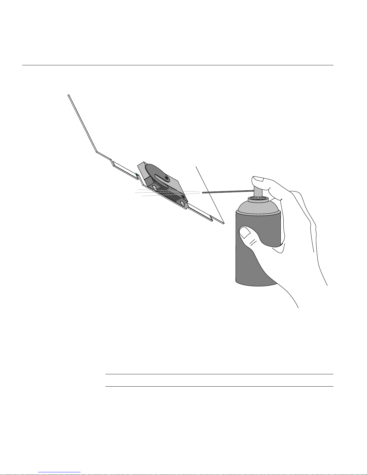
Figure A-2 Spraying the Compression Connector
3. Hold the can in a vertical position.
4. Place or hold the XIO board so that the rounded edge of the compression connector
faces up. Note that the rounded edge is completely closed, so that air cannot flow
into the connector, whereas the squared edge has an opening.
Caution: Spraying into the squared (open) edge of the connector can destroy it.
52 007-4506-001

Guidelines for Cleaning Compression Connectors
5. Position the XIO board at an angle to the can, so that the tip of the can’s applicator is
1 to 2 inches away from the first (topmost) row of pads. Do not allow the applicator
to touch the pads. When you spray, the air hits each pad and flows downward.
6. Start spraying. As you spray, move the spray along the length of the connector until
the entire length has been sprayed. Move down a few rows and again spray along
the entire length.
Note: Do not shake the can. Stop spraying if any visible material (for example, foam)
appears. This foam will blow away once you resume spraying just air.
7. Repeat until all the pads have been sprayed.
8. When you finish, cover the compression connector with its cap or immediately
install the board in an XIO slot.
007-4506-001 53


Appendix B
B. Choosing a Graphics Head (for Developers)
This appendix provides a brief overview of library routines that developers may need in
order to make applications work on a Dual Head system. Formore information about the
routines mentioned, see the appropriate man pages.
Note that once you open a window on a given head, the user cannot move it to the other
head via the window manager; if you want users to be able to move windows from one
head to another, your program must explicitly close the old window and open a new one
on the other head.
Using Multiple Graphics Heads Under OpenGL, X, or Mixed-Model IRIS GL
OpenGL, X, and mixed-model IRIS GL all use X calls to choose on which screen to
display; just pass the name of the desired display as the argument to
XOpenDisplay(3X11). (Pass NULL as the display name if you want to default to the
value of the DISPLAYenvironment variable.) You can then call RootWindow(3X11) with
the newly opened display, specifying whichever screen you want; then call
XCreateWindow(3X11) to create a window on the specified screen. After that, use the
usual OpenGL or X calls, as appropriate, to draw or display in the window.
This is the syntax for XOpenDisplay():
Display *XOpenDisplay(display_name)
char *display_name;
007-4506-001 55

B: Choosing a Graphics Head (for Developers)
For example, use the following code example to open a window on each head of a Dual
Head system:
#include <X11/Xlib.h>
#include <X11/Xutil.h>
#include <stdio.h>
void main(argc, argv)
int argc;
char **argv;
{
Display *display;
Window root0, root1, win0, win1;
/* Open the display specified in the DISPLAY variable. */
if ( (display = XOpenDisplay("")) == NULL )
fprintf(stderr, "%s: cannot connect to X server.\n",
/* Set up a root window for each screen. */
root0 = RootWindow(display, 0);
root1 = RootWindow(display, 1);
argv[0]);
/* Now create a window on each screen. */
win0 = XCreateSimpleWindow(display, root0, 0, 0, 100,
100, 0, 0, 0);
win1 = XCreateSimpleWindow(display, root1, 0, 0, 100,
100, 0, 0, 0);
/* Display the windows and flush the output buffer. */
XMapWindow(display, win0);
XMapWindow(display, win1);
XFlush(display);
/* Leave them up for ten seconds before exiting. */
sleep(10);
}
56 007-4506-001

Using Multiple Heads Under IRIS GL
Under IRIS GL, you select a head on which to run a window by using the
scrnselect(3G) function. If you do not call scrnselect()before opening a window
using winopen(3G), the window opens on whichever screen the user has specified in the
DISPLAY environment variable.
This is the syntax for scrnselect():
long scrnselect(gsnr)
long gsnr;
where gsnr is the screen number relative to the current server—that is, 0 for screen :0.0
or 1 for :1.0.
Specifying Screen Adjacency
If you include system configuration files such as /usr/lib/X11/xdm/Xservers with
your application, you may want to configure the layout of the heads, specifying which is
on the left and which on the right. For information on how to specify adjacency, see the
Xsgi man page, under the -hw option, or Chapter 2, “Duo Software Installation,” in this
guide.
Using Multiple Heads Under IRIS GL
007-4506-001 57


Appendix C
C. Cabling and Configuring PCI Ethernet Boards
This appendix provides information to help you configure PCI boards in your Octane or
Octane2 system and to determine how the ports on those boards will by identified by the
software. Configuration resources are provided in the last section of this appendix.
About the ioconfig.conf File
The ioconfig.conf file records and saves option board and port information after the
option board is installed in the Octane2 workstation. However, the file reserves the board
and port spaces if the option board is removed, and assigns new logical controller
numbers if the same type of board is inserted in a different PCI slot.
If you want a listing of only what is currently installed, remove the ioconfig.conf file
and restart your system. The file is rebuilt with information about the current hardware
configuration, reflecting what is currently installed.
Note: Rebuilding the ioconfig.conf file can change all of the maps between the
logical controller numbers and the physical portlocations, depending on whether option
boards have been moved to different slots or removed from the system.
Removing the ioconfig.conf File
If you need to place the PCI board (Ethernet/keyboard/mouse) in a different slot, move
the board to the new slot, and then remove the ioconfig.conf file. Removing the file
erases the record of the previous location so that the system does not think two boards of
the same type are installed. To remove the iconfig.conf file, follow these directions:
1. From Toolchest > Desktop, choose Open UNIX Shell.
2. Become superuser by typing su
007-4506-001 59

C: Cabling and Configuring PCI Ethernet Boards
3. Type: rm /etc/ioconfig.conf
4. Type: exit to exit superuser mode.
5. Restart the system. Restarting the system builds a new ioconfig.conf file.
Mapping the Logical Controller Numbers to the Physical Port Locations
Before you can connect cables, you need to map the logical port numbers to the physical
port locations. Follow these instructions:
1. From the Toolchest > Desktop, choose Open UNIX Shell.
2. At the prompt, type: cat /etc/ioconfig.conf
3. Read the following table, descriptions, and explanations to determine the correct
port location(s) for the cables you wish to connect.
You see a listing similar to the following example.
Table C-1 Identification of Information in the ioconfig.conf File
Logical
Controller #
2 /hw /node /xtalk /13 /pci /2 /scsi_ctlr
0 /hw /node /xtalk /13 /pci /1 /rns
2 /hw /node /xtalk /13 /pci /3 /pckb
2 /hw /node /xtalk /13 /pci /3 /pcms
1 /hw /node /xtalk /13 /pci /3 /ef
60 007-4506-001
Hard
ware Node
Bus
Type
Physical
XIO Slot ID Bus Type Slot ID
Port Type
(Abbreviation)
Serial
Port ID

Logical Controller Number Column
The Logical Controller Number is the number assigned to a port on an option board by
the operating system. The logical controller numbers assigned by the operating system
to a port on an option board always start higher than the last assigned port of the same
type on the system module. Ports of the same type are assigned incrementing port
numbers. For example, because there is one Ethernet port on the system module (which
is assigned logical number 0) logical number 1 is assigned to the first optional Ethernet
port that the software sees.
Hardware, Node, and Bus Type Columns
Ignore the Hardware,Node, and Bus Type columns containing XIO entries when looking
for information in this table. They appear in the ioconfig.conf file to report that
hardware is being probed, on one node, using XIO at one point and PCI at another within
the workstation.
Mapping the Logical Controller Numbers to the Physical Port Locations
007-4506-001 61

C: Cabling and Configuring PCI Ethernet Boards
Physical XIO Slot ID Column
XIO Slot ID (software)
SCSI
Ethernet
XIO Slot ID (software)
Serial ports
RL
In Out
2
System module
15
8
1
PCI ID #1
PCI ID #2
PCI ID #3
PCI module
13
A
12
D
10
B
11
C
9
XIO module
Quadrant ID (hardware)
XIO Slot ID (software)
XIO Slot ID (software)
Quadrant ID (hardware)
XIO Slot ID (software)
Figure C-1 Physical XIO Identification Numbers and Software Designations
Use Figure C-1 to determine the physical XIO Slot ID number. After the system module
itself, the PCI module is the first XIO module probed. Its number is 13.
In aVPro Octane2 system, the primary graphics head occupies physical quadrants A and
B, but only uses the XIO connector in slot B. Its location in software is therefore XIO Slot
ID 11.
62 007-4506-001

Mapping the Logical Controller Numbers to the Physical Port Locations
In a Dual Head VPro Octane2 system, the secondary graphics head occupies physical
quadrants C and D, but only uses the XIO connector in slot D. Its location in software is
therefore XIO Slot ID 10.
Note: Physical port numbers are assigned in XIO probing order, which starts at the
highest XIO Slot ID and descends. For example, the Ethernet port on the system module
(XIO Slot ID 15) will be assigned a logical number 0, before an Ethernet port on a board
in the PCI module (XIO Slot ID 13) is assigned logical number 1, because XIO Slot ID 15
is probed before XIO Slot ID 13.
Table C-2 shows the XIO Slot IDs in numeric order and the device or location to which
each is mapped.
Table C-2 XIO Slot ID Mapping
XIO Slot ID # Device or Location
8 System module (heart chip)
9 XIO Quadrant C (lower right of XIO module)
10 XIO Quadrant D (lower left of XIO module)
11 XIO Quadrant B (upper right of XIO module)
12 XIO Quadrant A (upper left of XIO module)
13 PCI module
14 (not assigned)
15 System module (bridge chip: I/O functions)
Bus Type Column
The column that contains PCI entries should be read only in conjunction with the
Physical XIO Slot ID column that comes before it. If the Physical XIO Slot ID number is
13, the board to which a logical controller number has been assigned is in the PCI
module.
007-4506-001 63

C: Cabling and Configuring PCI Ethernet Boards
Slot ID Column
The Slot ID column refers to the physical location of the option board in the PCI module.
Again referring to the example shown in Table C-1, we see that all entries in this table
have physical XIO Slot ID number 13, which means they are all in the PCI module.
We can see that the first listing is a board in PCI slot 2 (the Slot ID column contains a 2),
and that this board has one port, abbreviated scsi_ctrl (which means this is a SCSI
controller port).
The second listing is a board in PCI slot 1 (the Slot ID column contains a 1). This board
has one port, abbreviated rns (which, as we’ll see later, is an FDDI or CDDI port).
The third, fourth and fifth listings are a single board in PCI slot 3 (the Slot ID column for
all three entries contains a 3). This board has three ports, abbreviated pckb, pcms, and
ef (which, as we’ll see later, are keyboard, mouse, and Ethernet ports, respectively).
Figure C-2 shows the location of each of the slots in the PCI module.
ID #3
Figure C-2 PCI Module Slot Numbers
64 007-4506-001
ID #1
ID #2

Port Type Column
Serial Port ID Column
Mapping the Logical Controller Numbers to the Physical Port Locations
Table C-3 lists the port type abbreviations and their definitions.
Table C-3 Port Type Abbreviations and Definitions
Abbreviation Definition
ef Ethernet
rns FDDI or CDDI
pckb keyboard
pcms mouse
tty serial
scsi_ctlr SCSI controller
Because each pair of XIO serial ports share a bus, this column identifies which XIO serial
port is on which bus.
007-4506-001 65

C: Cabling and Configuring PCI Ethernet Boards
After Installing the Board and Cables
When the board is installed and connected and the Octane2 workstation is powered on,
use the following information for configuration.
Certain PCI boards require some configuration, others do not. Use the table below to
determine whether you need to configure the board.
Table C-4 Determining Which Boards to Configure
Configuration Needed Configuration Not Needed
All networking boards Mouse, keyboard, SCSI, Radical
Refer to the Personal System Administration Guide or IRIX Admin: Networking and Mail for
instructions on configuring software. Both documents are online and accessible from
Toolchest > Help > Online Books. The Personal System Administration Guide is underSGI
End User, and the IRIX Admin: Networking and Mail guide is under SGI Admin.
66 007-4506-001

Index
A
adding swap space, 24
adding users, 26
attachment
regulatory label, 15
B
back up
system, 6
C
cables
connecting
Ethernet, 17
monitor, 18
primary keyboard, 17
primary mouse, 17
secondary keyboard, 19
secondary mouse, 19
sound, 17
choosing a graphics head, 55
compression connectors
cleaning, 51
description, 49
handling instructions, 50
configuring
input devices, 28
serial input devices, 28
contents
Duo kit, 1
CPUs
minimum quantity required for Duo, 3
D
disk drive
installation, 10
removal, 43
Dual Head, enabling, 34
Duo
description, 1
kit contents, 1
requirements for upgrade, 3
F
File QuickFind, 35
G
graphics head
choosing, 55
007-4506-001 67

Index
H
handling instruction
compression connectors, 50
hard disk drive
mounting, 23
Host QuickFind
, 35
I
input devices
configuring
, 28
installation
disk drive, 10
PCI card, 13
PCI card cage, 13
PCI module, 13
RAM, 11
system memory, 11
internal drive installation
verifying, 22
ioconfig.conf file, 59
removing, 59
IRIX version
minimum for Duo, 5
verifying, 5
O
option drive, 22
installation, 10
mounting, 23
removal, 43
P
PCI board installation
verifying, 32
PCI card
installation, 13
removal, 46
PCI card cage
installation, 13
removal, 46
PCI module
installation, 13
removal, 46
port type abbreviations, 65
primary head
selecting, 33
R
M
memory installation
verifying, 31
minimum IRIX version, 5
mounting the option drive, 23
multiple graphics heads under OpenGL or
mixed-model GL, 55
multiple heads under IRIS GL, 57
68 007-4506-001
RAM
installation, 11
removal, 44
regulatory label attachment, 15
removal
disk drive, 43
PCI card, 46
PCI card cage, 46
PCI module, 46
RAM, 44
system memory, 44

Index
S
screen adjacency, specifying, 57
SCSI devices, 22
Search For Files
, 35
secondary head
selecting
, 33
selecting the primary or secondary head, 33
serial input devices
configuring
Slot ID
, 64
, 28
swap space
adding, 24
system backup, 6
system memory
installation, 11
removal, 44
T
troubleshooting problems with Duo, 39
X
XIO Slot IDs, 63
Xserver file, 7
U
upgrade requirements
Duo, 3
users
adding, 26
V
verifying
internal drive installation, 22
memory installation, 31
PCI board installation, 32
007-4506-001 69

 Loading...