

Page 1

Silicon Graphics® O2+™ Workstation
Hardware Reference Guide
Document Number 007-4486-001
Page 2

CONTRIBUTORS
Written by Judy Muchowski
Updated by Linda Rae Sande and Chrystie Danzer
Illustrated by Dany Galgani and Chrystie Danzer
Production by Chrystie Danzer and Karen Jacobson
Usability by Richard Wright
Engineering contributions by Charles Alexander, Bob Sanders, and Ian Yoch
COPYRIGHT
© 2002, Silicon Graphics, Inc. All rights reserved; provided portions may be copyright in third parties, as indicated elsewhere herein. No
permission is granted to copy, distribute, or create derivative works from the contents of this electronic documentation in any manner, in whole
or in part, without the prior written permission of Silicon Graphics, Inc.
RESTRICTED RIGHTS LEGEND
The electronic (software) version of this document was developed at private expense; if acquired under an agreement with the USA government
or any contractor thereto, it is acquired as "commercial computer software" subject to the provisions of its applicable license agreement, as
specified in (a) 48 CFR 12.212 of the FAR; or, if acquired for Department of Defense units, (b) 48 CFR 227-7202 of the DoD FAR Supplement; or
sections succeeding thereto. Contractor/manufacturer is Silicon Graphics, Inc., 1600 Amphitheatre Pkwy 2E, Mountain View, CA 94043-1351.
TRADEMARKS AND ATTRIBUTIONS
Silicon Graphics, the Silicon Graphics logo, and IRIX are registered trademarks, and SGI, O2+, and O2Cam are trademarks of Silicon Graphics,
Inc. Apple and Macintosh are registered trademarks of Apple Computer, Inc. Kensington is a registered trademark of Kensington Microware
Limited. Logitech is a trademark of Logitech. Spaceball is a registered trademark of Spaceball Spatial Systems, Inc.
Page 3

Record of Revision
Version Description
001 January 2002
Revised from O2 Workstation Hardware Reference Guide
007-4486-001 iii
Page 4

Page 5

Contents
Figures . . . . . . . . . . . . . . . . . . . . . . . . . . ix
Tables . . . . . . . . . . . . . . . . . . . . . . . . . . xv
Introduction . . . . . . . . . . . . . . . . . . . . . . . xvii
Related Publications . . . . . . . . . . . . . . . . . . . . . xvii
Conventions . . . . . . . . . . . . . . . . . . . . . . . xviii
Reader Comments . . . . . . . . . . . . . . . . . . . . . . xviii
1. Getting Started . . . . . . . . . . . . . . . . . . . . . . . 1
Overview . . . . . . . . . . . . . . . . . . . . . . . . . 1
Checking Your Shipment . . . . . . . . . . . . . . . . . . . . . 6
Setting Up the O2+ Workstation . . . . . . . . . . . . . . . . . . . 7
Ergonomics Information . . . . . . . . . . . . . . . . . . . . 11
Registering Your Workstation . . . . . . . . . . . . . . . . . . . 12
Other Sources of Information . . . . . . . . . . . . . . . . . . . 12
IRIS InSight Document Library . . . . . . . . . . . . . . . . . . 12
CD Installation . . . . . . . . . . . . . . . . . . . . . . 13
Quick Answers . . . . . . . . . . . . . . . . . . . . . . 14
InfoSearch . . . . . . . . . . . . . . . . . . . . . . . . 14
SGI Technical Publications Library . . . . . . . . . . . . . . . . . 14
Turning the Workstation On or Off . . . . . . . . . . . . . . . . . . 15
Setting Up the O2Cam Digital Video Camera . . . . . . . . . . . . . . .16
Securing the O2+ Workstation . . . . . . . . . . . . . . . . . . . 21
Removing the Lockbar . . . . . . . . . . . . . . . . . . . . 23
Locating Your Workstation’s Serial Number . . . . . . . . . . . . . . .23
2. Installing or Removing Memory and Option Boards . . . . . . . . . . . . 27
Removing the System Module . . . . . . . . . . . . . . . . . . . 27
Installing Memory Modules . . . . . . . . . . . . . . . . . . . . 32
007-4486-001 v
Page 6

Contents
Removing Memory Modules . . . . . . . . . . . . . . . . . . . . 36
Installing a PCI Board in an RM7000class Workstation . . . . . . . . . . . . 38
Removing a PCI Board in an RM7000class Workstation . . . . . . . . . . . . 44
Installing a PCI Board in an R12000class Workstation . . . . . . . . . . . . . 47
Removing a PCI Board in an R12000class Workstation . . . . . . . . . . . . 50
Installing an Option Board . . . . . . . . . . . . . . . . . . . . 51
Removing the PCI Tray in an RM7000class Workstation . . . . . . . . . . . 57
Removing the PCI Tray in an R12000class Workstation . . . . . . . . . . . 58
Reinstalling the PCI Tray in an RM7000class Workstation . . . . . . . . . . 60
Reinstalling the PCI Tray in an R12000class Workstation. . . . . . . . . . . 63
Removing an Option Board . . . . . . . . . . . . . . . . . . . . 66
Reinstalling the System Module . . . . . . . . . . . . . . . . . . . 69
Verifying the Hardware Installation . . . . . . . . . . . . . . . . . . 73
3. Installing or Removing Peripherals. . . . . . . . . . . . . . . . . . 75
Installing a Second Internal Hard Drive in an RM7000class Workstation . . . . . . . 75
Removing the Second Internal Hard Drive in an RM7000class workstation . . . . . . 87
Connecting External SCSI Devices . . . . . . . . . . . . . . . . . . 91
Choosing a SCSI Address for the External Device . . . . . . . . . . . . . 92
Setting the SCSI Address on the External Device . . . . . . . . . . . . . 93
Connecting One External SCSI Device . . . . . . . . . . . . . . . .93
Connecting More Than One External SCSI Device . . . . . . . . . . . . 95
Connecting Serial Devices . . . . . . . . . . . . . . . . . . . . . 99
Connecting Audio and Video Devices . . . . . . . . . . . . . . . . 100
Connecting Audio Devices . . . . . . . . . . . . . . . . . . 101
Connecting Video Devices . . . . . . . . . . . . . . . . . . 102
4. Troubleshooting . . . . . . . . . . . . . . . . . . . . . . 103
Diagnosing the Problem . . . . . . . . . . . . . . . . . . . . 103
Running Diagnostic Tests . . . . . . . . . . . . . . . . . . . . 106
Power-on Tests. . . . . . . . . . . . . . . . . . . . . . 106
Confidence Tests . . . . . . . . . . . . . . . . . . . . . 107
IDE Tests . . . . . . . . . . . . . . . . . . . . . . . 107
Recovering from System Crash . . . . . . . . . . . . . . . . . . 108
vi 007-4486-001
Page 7

Contents
Disabling the System Maintenance Password . . . . . . . . . . . . . . .111
Service and Support Information . . . . . . . . . . . . . . . . . .115
5. Ordering, Removing, Upgrading, Installing Replacement Parts . . . . . . . . .117
Ordering a Replacement Part . . . . . . . . . . . . . . . . . . .117
Replacing the System Module . . . . . . . . . . . . . . . . . . .119
Replacing the RM7000class CPU Module . . . . . . . . . . . . . . . .120
Replacing the R12000class CPU Module . . . . . . . . . . . . . . . .126
Replacing the System Drive . . . . . . . . . . . . . . . . . . . .137
Replacing the Audio-visual Module. . . . . . . . . . . . . . . . . .142
Replacing the Power Supply . . . . . . . . . . . . . . . . . . . .149
Replacing the CD-ROM Drive . . . . . . . . . . . . . . . . . . .158
Replacing the Chassis . . . . . . . . . . . . . . . . . . . . . .176
Replacing the PCB on the PCI Tray . . . . . . . . . . . . . . . . . .178
6. Safety and Regulatory Information . . . . . . . . . . . . . . . . .179
Regulatory Declarations . . . . . . . . . . . . . . . . . . . . .179
CMN Number. . . . . . . . . . . . . . . . . . . . . . .180
CE Notice and Manufacturer's Declaration of Conformity . . . . . . . . . .180
Electromagnetic Emissions . . . . . . . . . . . . . . . . . . .180
FCC Notice (USA Only) . . . . . . . . . . . . . . . . . . .180
Industry Canada Notice (Canada Only) . . . . . . . . . . . . . .181
VCCI Notice (Japan Only) . . . . . . . . . . . . . . . . . .182
Chinese Class A Regulatory Notice . . . . . . . . . . . . . . .182
Korean Class A Regulatory Notice. . . . . . . . . . . . . . . .182
Shielded Cables . . . . . . . . . . . . . . . . . . . . . .182
Electrostatic Discharge . . . . . . . . . . . . . . . . . . . .183
Laser Compliance Statement . . . . . . . . . . . . . . . . . .183
Lithium Battery Statement . . . . . . . . . . . . . . . . . . .183
Safety Instructions . . . . . . . . . . . . . . . . . . . . . . .183
Human Factors Guidelines for Setting Up Your O2+ Workstation . . . . . . . . .185
ANSI Standard for Visual Display Terminal Workstations . . . . . . . . . .185
CAD Operator Preferences . . . . . . . . . . . . . . . . . . .187
007-4486-001 vii
Page 8

Contents
A. Technical Specifications . . . . . . . . . . . . . . . . . . . . 189
Cable Pinout Assignments . . . . . . . . . . . . . . . . . . . 189
Serial . . . . . . . . . . . . . . . . . . . . . . . . 190
Parallel . . . . . . . . . . . . . . . . . . . . . . . . 190
Ethernet 10-Base T/100-Base T . . . . . . . . . . . . . . . . . 191
Keyboard and Mouse . . . . . . . . . . . . . . . . . . . . 192
SCSI . . . . . . . . . . . . . . . . . . . . . . . . . 192
Audio . . . . . . . . . . . . . . . . . . . . . . . . 194
Composite Video (Analog) In and Out . . . . . . . . . . . . . . . 195
S-Video (Analog) In and Out . . . . . . . . . . . . . . . . . . 196
Digital Video In and Out . . . . . . . . . . . . . . . . . . . 197
Monitor . . . . . . . . . . . . . . . . . . . . . . . . 198
Stereo View. . . . . . . . . . . . . . . . . . . . . . . 199
Presenter 1280 Flat Panel Adapter (Optional) . . . . . . . . . . . . . 200
Digital Video Option Port (Optional) . . . . . . . . . . . . . . . 201
Serial Cables and Converters . . . . . . . . . . . . . . . . . . . 202
Printer/Dumb Terminal Serial Cable . . . . . . . . . . . . . . . 202
PC Modem Serial Cable . . . . . . . . . . . . . . . . . . . 203
Serial Port Converters . . . . . . . . . . . . . . . . . . . . 204
RS-422 Converter (DB-9 Female) for Video Deck Control . . . . . . . . 205
Macintosh to MIDI Converter (DB-9 Female to MiniDIN-8 Female) . . . . . 206
O2 Camera Technical Specifications . . . . . . . . . . . . . . . . . 207
Physical Environment Specifications . . . . . . . . . . . . . . . . 208
Glossary . . . . . . . . . . . . . . . . . . . . . . . . . 209
Index. . . . . . . . . . . . . . . . . . . . . . . . . . 225
viii 007-4486-001
Page 9

Figures
Figure 1-1 Front View of the O2+ Workstation . . . . . . . . . . 2
Figure 1-2 Rear View of the O2+ RM7000class Workstation . . . . . . 3
Figure 1-3 Rear View of the O2+ R12000class Workstation . . . . . . 4
Figure 1-4 Side Panel Audio and Video Ports . . . . . . . . . . 5
Figure 1-5 O2+ Workstation Parts. . . . . . . . . . . . . . 6
Figure 1-6 Connecting the Keyboard and Mouse to the Workstation . . . . 7
Figure 1-7 Connecting the Network Cable and the Camera to the
Workstation . . . . . . . . . . . . . . . . . 8
Figure 1-8 Connecting the Monitor to the Workstation. . . . . . . . 9
Figure 1-9 Connecting the Power Cables to the Monitor and to the
Workstation . . . . . . . . . . . . . . . . . 10
Figure 1-10 Turning On the Monitor and the Workstation . . . . . . . 11
Figure 1-11 Insight Icon . . . . . . . . . . . . . . . . . 12
Figure 1-12 Toolchest . . . . . . . . . . . . . . . . . 14
Figure 1-13 Turning the Workstation On or Off . . . . . . . . . . 15
Figure 1-14 Power Off Message. . . . . . . . . . . . . . . 16
Figure 1-15 Connecting the O2Cam to the Workstation . . . . . . . . 17
Figure 1-16 Front View of the O2Cam . . . . . . . . . . . . . 18
Figure 1-17 Using the O2Cam’s Built-in Microphone . . . . . . . . 19
Figure 1-18 Setting Up the O2Cam on Your Monitor. . . . . . . . . 20
Figure 1-19 Attaching the Lockbar to the Workstation . . . . . . . . 21
Figure 1-20 Sliding the Lockbar. . . . . . . . . . . . . . . 22
Figure 1-21 Locking the O2+ Workstation. . . . . . . . . . . . 23
Figure 1-22 Locating the Serial Number On the Rear . . . . . . . . 24
Figure 1-23 Locating the Serial Number Inside the Workstation . . . . . 25
Figure 2-1 Turning Off the O2+ Workstation . . . . . . . . . . 28
Figure 2-2 Disconnecting the Power Cables . . . . . . . . . . . 29
007-4486-001 ix
Page 10

Figures
Figure 2-3 Pulling Down the Lever on the System Module . . . . . . . 30
Figure 2-4 Remove the System Module from the Chassis . . . . . . . 31
Figure 2-5 Laying the System Module on a Flat Surface. . . . . . . . 31
Figure 2-6 Attaching the Wrist Strap . . . . . . . . . . . . . 33
Figure 2-7 Locating the DIMM Banks . . . . . . . . . . . . . 34
Figure 2-8 Top View of the DIMM Banks . . . . . . . . . . . . 34
Figure 2-9 Installing the Memory Modules . . . . . . . . . . . 35
Figure 2-10 Checking the DIMM Installation . . . . . . . . . . . 36
Figure 2-11 Attaching the Wrist Strap . . . . . . . . . . . . . 37
Figure 2-12 Removing the Memory Module . . . . . . . . . . . 37
Figure 2-13 Releasing the PCI Tray . . . . . . . . . . . . . . 38
Figure 2-14 Removing the PCI Tray. . . . . . . . . . . . . . 39
Figure 2-15 Removing the Screw and Filler Panel . . . . . . . . . . 40
Figure 2-16 Installing the PCI Board . . . . . . . . . . . . . 41
Figure 2-17 Returning the Lever to Its Starting Position . . . . . . . . 42
Figure 2-18 Replacing the PCI Tray in the System Module . . . . . . . 43
Figure 2-19 PCI Tray Seated Correctly . . . . . . . . . . . . . 44
Figure 2-20 Releasing the PCI Tray . . . . . . . . . . . . . . 45
Figure 2-21 Removing the PCI Tray. . . . . . . . . . . . . . 45
Figure 2-22 Removing the Screw and the PCI Board . . . . . . . . . 46
Figure 2-23 Replacing the Filler Panel and Screw on the PCI Tray . . . . . 47
Figure 2-24 Removing the Screw and Filler Panel . . . . . . . . . . 48
Figure 2-25 Installing the PCI Board on the R12000class Workstation . . . . 49
Figure 2-26 Securing the PCI Board . . . . . . . . . . . . . . 49
Figure 2-27 Removing the Screw That Secures the PCI Board . . . . . . 50
Figure 2-28 Replacing the Filler Panel and Screw . . . . . . . . . . 51
Figure 2-29 Option Board . . . . . . . . . . . . . . . . 52
Figure 2-30 Attaching the Wrist Strap . . . . . . . . . . . . . 53
Figure 2-31 Removing the I/O Filler Panel. . . . . . . . . . . . 54
Figure 2-32 Positioning the Option Board . . . . . . . . . . . . 55
Figure 2-33 Aligning the Option Board . . . . . . . . . . . . . 55
Figure 2-34 Seating the Option Board Viewed from the Side . . . . . . 56
Figure 2-35 Installing the Two Screws . . . . . . . . . . . . . 56
x 007-4486-001
Page 11

Figures
Figure 2-36 Releasing the PCI Tray. . . . . . . . . . . . . . 57
Figure 2-37 Removing the PCI Tray . . . . . . . . . . . . . 58
Figure 2-38 Removing the Screws from the Faceplate . . . . . . . . 59
Figure 2-39 Removing the Faceplate from the System Module . . . . . . 59
Figure 2-40 Removing the PCI Tray from the R12000class System Module . . 60
Figure 2-41 Returning the Lever to Its Starting Position . . . . . . . . 61
Figure 2-42 Replacing the PCI Tray in the System Module . . . . . . . 62
Figure 2-43 PCI Tray Seated Correctly . . . . . . . . . . . . . 63
Figure 2-44 Replacing the R12000class PCI Tray in the System Module . . . 64
Figure 2-45 Replacing the Faceplate . . . . . . . . . . . . . 65
Figure 2-46 Replacing Two Screws on the Faceplate . . . . . . . . . 65
Figure 2-47 Replacing Five Screws on the Faceplate . . . . . . . . . 66
Figure 2-48 Attaching the Wrist Strap . . . . . . . . . . . . . 67
Figure 2-49 Removing the Option Board . . . . . . . . . . . . 68
Figure 2-50 Returning the System Module to Its Upright Position . . . . . 69
Figure 2-51 Reinstalling the System Module in the Chassis . . . . . . . 70
Figure 2-52 Securing the System Module in Place . . . . . . . . . 71
Figure 2-53 Connecting the Power Cable . . . . . . . . . . . . 72
Figure 2-54 Turning On the Workstation . . . . . . . . . . . . 73
Figure 2-55 The Toolchest . . . . . . . . . . . . . . . . 73
Figure 3-1 Turning Off the Workstation . . . . . . . . . . . . 76
Figure 3-2 Locating the Optional Drive Bay . . . . . . . . . . . 77
Figure 3-3 Disconnecting the Power Cable and Other Cables . . . . . . 78
Figure 3-4 Releasing the Audio-visual Module . . . . . . . . . . 79
Figure 3-5 Sliding Out the Audio-visual Module . . . . . . . . . 80
Figure 3-6 Removing the Panel from the Optional Drive bay . . . . . . 81
Figure 3-7 Installing the Second Hard Drive Module . . . . . . . . 82
Figure 3-8 Securing the Second Hard Drive Module . . . . . . . . 83
Figure 3-9 Reinstalling the Audio-visual Module in the Chassis . . . . . 84
Figure 3-10 Securing the Audio-visual Module . . . . . . . . . . 85
Figure 3-11 Connecting the Power Cable and Other Cables. . . . . . . 86
Figure 3-12 Turning On the Workstation . . . . . . . . . . . . 86
Figure 3-13 Turning Off the Workstation . . . . . . . . . . . . 87
007-4486-001 xi
Page 12

Figures
Figure 3-14 Releasing the Optional Drive Module . . . . . . . . . 88
Figure 3-15 Sliding the Second Hard Drive out of the Chassis . . . . . . 89
Figure 3-16 Replacing the Filler Panel . . . . . . . . . . . . . 90
Figure 3-17 Reconnecting the Cables . . . . . . . . . . . . . 91
Figure 3-18 Turning Off the Workstation . . . . . . . . . . . . 93
Figure 3-19 Connecting One External Device to the Workstation . . . . . 94
Figure 3-20 Turning Off the Workstation . . . . . . . . . . . . 96
Figure 3-21 Connecting More Than One Device in a Daisy-chain . . . . . 98
Figure 3-22 Locating the Serial Ports . . . . . . . . . . . . . 99
Figure 3-23 Audio and Video Ports . . . . . . . . . . . . . 101
Figure 4-1 Diagnostic Flow Chart #1 . . . . . . . . . . . . 104
Figure 4-2 Diagnostic Flow Chart #2 . . . . . . . . . . . . 105
Figure 4-3 System Diagnostic Tests . . . . . . . . . . . . 106
Figure 4-4 System Startup Message . . . . . . . . . . . . 107
Figure 4-5 Pressing the Reset Button . . . . . . . . . . . . 108
Figure 4-6 System Startup Message . . . . . . . . . . . . 109
Figure 4-7 System Recovery Menu. . . . . . . . . . . . . 109
Figure 4-8 Turning Off the Workstation . . . . . . . . . . . 112
Figure 4-9 Attaching the Wrist Strap . . . . . . . . . . . . 113
Figure 4-10 Removing the Jumper . . . . . . . . . . . . . 114
Figure 4-11 Installing the Jumper . . . . . . . . . . . . . 115
Figure 5-1 Releasing the PCI Tray on the RM7000class Workstation . . . 120
Figure 5-2 Removing the PCI Tray. . . . . . . . . . . . . 121
Figure 5-3 Attaching the Wrist Strap . . . . . . . . . . . . 121
Figure 5-4 Removing the Phillips Screws on the RM7000class CPU Module . 122
Figure 5-5 Removing the RM7000class CPU Module . . . . . . . 123
Figure 5-6 Installing the Replacement CPU Module . . . . . . . . 124
Figure 5-7 Replacing the PCI Tray in the System Module . . . . . . 125
Figure 5-8 PCI Tray Seated Correctly . . . . . . . . . . . . 126
Figure 5-9 Removing Seven Screws from the Faceplate . . . . . . . 127
Figure 5-10 Removing the Faceplate from the System Module . . . . . 128
Figure 5-11 Releasing the PCI Tray from the System Module . . . . . 129
Figure 5-12 Attaching the Wrist Strap . . . . . . . . . . . . 130
xii 007-4486-001
Page 13

Figures
Figure 5-13 Removing the Screws from the R12000class CPU Module. . . .131
Figure 5-14 Removing the R12000class CPU Module . . . . . . . .131
Figure 5-15 Securing the R12000class CPU Module . . . . . . . . .132
Figure 5-16 Replacing the PCI Tray in the R12000class System Module . . .133
Figure 5-17 Replacing the Faceplate . . . . . . . . . . . . .134
Figure 5-18 Replacing Two Screws on the Underside . . . . . . . .135
Figure 5-19 Replacing Five Screws on the Faceplate . . . . . . . . .136
Figure 5-20 Turning Off the Workstation . . . . . . . . . . . .137
Figure 5-21 Removing the Power Cables . . . . . . . . . . . .138
Figure 5-22 Releasing the Drive Tray . . . . . . . . . . . . .139
Figure 5-23 Removing the System Drive Module from the Chassis . . . .140
Figure 5-24 Installing the Replacement System Drive Module . . . . . .140
Figure 5-25 Securing the System Drive Module . . . . . . . . . .141
Figure 5-26 Reconnecting the Power Cable . . . . . . . . . . .142
Figure 5-27 Turning Off the Workstation . . . . . . . . . . . .143
Figure 5-28 Removing the Cables from the Audio-visual Module . . . . .144
Figure 5-29 Releasing the Audio-visual Module . . . . . . . . . .145
Figure 5-30 Removing the Audio-visual Module from the Chassis. . . . .146
Figure 5-31 Installing the Replacement Audio-visual Module . . . . . .147
Figure 5-32 Securing the Audio-visual Module . . . . . . . . . .147
Figure 5-33 Reconnecting the Audio-visual Cables . . . . . . . . .148
Figure 5-34 Turning on the Workstation . . . . . . . . . . . .148
Figure 5-35 Turning Off the Workstation . . . . . . . . . . . .149
Figure 5-36 Removing the Power Cable . . . . . . . . . . . .150
Figure 5-37 Removing the Bezel from the Power Supply . . . . . . .151
Figure 5-38 Releasing the Power Supply . . . . . . . . . . . .152
Figure 5-39 Removing the Power Supply from the Chassis . . . . . . .153
Figure 5-40 Installing the Replacement Power Supply . . . . . . . .154
Figure 5-41 Locking the Power Supply in Place . . . . . . . . . .155
Figure 5-42 Replacing the Bezel on the Power Supply . . . . . . . .156
Figure 5-43 Reconnecting the Power Cable . . . . . . . . . . .157
Figure 5-44 Opening the CD-ROM Drive . . . . . . . . . . . .158
Figure 5-45 Removing the CD-ROM Drive Faceplate . . . . . . . .159
007-4486-001 xiii
Page 14

Figures
Figure 5-46 Removing the Power Supply Bezel . . . . . . . . . 160
Figure 5-47 Removing the Top Cover of the CD-ROM Drive . . . . . 161
Figure 5-48 Removing the Two Phillips Screws . . . . . . . . . 162
Figure 5-49 Removing the Outer Cover. . . . . . . . . . . . 163
Figure 5-50 Removing the Screws from the CD-ROM Drive . . . . . . 164
Figure 5-51 Removing the CD-ROM Drive. . . . . . . . . . . 165
Figure 5-52 Disconnecting the SCSI and Power Cables . . . . . . . 166
Figure 5-53 Reconnecting the SCSI and Power Cables . . . . . . . 167
Figure 5-54 Installing the Replacement CD-ROM Drive . . . . . . . 168
Figure 5-55 Securing the CD-ROM Drive . . . . . . . . . . . 169
Figure 5-56 Replacing the Outer Cover . . . . . . . . . . . . 170
Figure 5-57 Securing the Outer Cover . . . . . . . . . . . . 171
Figure 5-58 Replacing the Top Cover of the CD-ROM Drive. . . . . . 172
Figure 5-59 Replacing the Power Supply Bezel . . . . . . . . . 173
Figure 5-60 Replacing the CD-ROM Faceplate. . . . . . . . . . 174
Figure 5-61 Reconnecting the Power Cable . . . . . . . . . . 175
Figure 5-62 Stripped-down Workstation Chassis . . . . . . . . . 177
Figure 6-1 VCCI Notice (Japan Only) . . . . . . . . . . . . 182
Figure 6-2 Chinese Class A Regulatory Notice . . . . . . . . . 182
Figure 6-3 Korean Class A Regulatory Notice . . . . . . . . . 182
Figure 6-4 Basic Parameters of VDT Workstation Adjustment . . . . . 186
Figure A-1 Audio Ports Pinout Assignments . . . . . . . . . . 195
Figure A-2 S-Video (Analog) Port Pinout Assignments . . . . . . . 196
xiv 007-4486-001
Page 15

Tables
Table 5-1 Information Needed for Support Call . . . . . . . . .118
Table 6-1 ANSI/HFS 100-1988 Guidelines for VDT Workplace Adjustment .186
Table 6-2 Workstation Adjustments Preferred by CAD User . . . . . .187
Table A-1 Serial Port Pinout Assignments . . . . . . . . . . .190
Table A-2 Parallel Port (IEEE 1284-C) Pinout Assignments . . . . . .190
Table A-3 Ethernet 10-Base T/100-Base T Port Pinout Assignments . . . .191
Table A-4 Keyboard and Mouse Ports (6-pin MiniDIN) Pinout Assignments .192
Table A-5 SCSI Port Pinout Assignments . . . . . . . . . . .192
Table A-6 Analog Composite Video Port Pinout Assignments . . . . .195
Table A-7 Digital Video Port for O2Cam . . . . . . . . . . .197
Table A-8 Monitor Port (DSUB15) Pinout Assignments . . . . . . .198
Table A-9 Optional Stereo View Port Pin Assignments . . . . . . .199
Table A-10 Presenter 1280 Monitor Port (Optional) . . . . . . . . .200
Table A-11 DB-9 Connector Pinout Assignments . . . . . . . . .201
Table A-12 Cable Pinout Assignments for Printer/Dumb Terminal Serial
Cable . . . . . . . . . . . . . . . . . . .203
Table A-13 Cable Pinout Assignments for PC Modem Cable . . . . . .204
Table A-14 RS-422 Converter (DB-9 Female): Workstation End . . . . .205
Table A-15 RS-422 Converter (DB-9 Female): Video Deck End . . . . . .205
Table A-16 Macintosh to MIDI Converter (DB-9 Female): Workstation End . .206
Table A-17 Macintosh to MIDI Converter (MiniDIN-8): MIDI Interface End . .206
Table A-18 O2Cam Technical Specifications . . . . . . . . . . .207
Table A-19 Physical Environment Specifications for the O2+ Workstation . .208
007-4486-001 xv
Page 16

Page 17

Introduction
Silicon Graphics O2+ Workstation Hardware Reference Guide is your guide to installing,
troubleshooting, and repairing your workstation. Specifically, it explains how to:
• Set up the workstation, including an overview of the hardware (Chapter 1, “Getting
Started”).
• Install and remove memory and option boards (Chapter 2, “Installing or Removing
Memory and Option Boards”).
• Install and remove internal and external peripheral devices (Chapter 3, “Installing
or Removing Peripherals”).
• Diagnose hardware problems (Chapter 4, “Troubleshooting”).
• Order and replace faulty parts (Chapter 5, “Ordering, Removing, Upgrading,
Installing Replacement Parts”).
• Create a safe and comfortable environment for your workstation and maintain the
system correctly (Chapter 6, “Safety and Regulatory Information”).
• Find technical specifications (Appendix A, “Technical Specifications”).
Related Publications
Silicon Graphics O2+ Workstation User’s Guide contains additional information that may be
helpful. For more information about related publications, see “Other Sources of
Information” in Chapter 1.
To obtain SGI documentation, see the SGI Technical Publications Library at
http://techpubs.sgi.com.
007-4486-001 xvii
Page 18

Introduction
Conventions
The following conventions are used throughout this document:
Convention Meaning
command This fixed-space font denotes literal items such as commands, files,
routines, path names,signals, messages, andprogramming language
structures.
variable Italic typeface denotes variable entries and words or concepts being
defined.
user input This bold, fixed-space font denotes literal items that the user enters
in interactive sessions. Output is shown in nonbold, fixed-space font.
[] Brackets enclose optional portions of a command or directive line.
... Ellipses indicate that a preceding element can be repeated.
manpage(x) Man page section identifiers appear in parentheses after man page
names.
Reader Comments
If you have comments about the technical accuracy, content, or organization of this
document, please contact SGI. Be sure to include the title and document number of the
manual with your comments. (Online, the document number is located in the front
matter of the manual. In printed manuals, the document number is located at the bottom
of each page.)
You can contact us in any of the following ways:
• Send e-mail to the following address:
techpubs@sgi.com
• Use the Feedback option on the Technical Publications Library Web page:
http://techpubs.sgi.com
• Contact your customer service representative and ask that an incident be filed in the
SGI incident tracking system.
xviii 007-4486-001
Page 19

• Send mail to the following address:
Technical Publications
SGI
1600 Amphitheatre Pkwy., M/S 535
Mountain View, California 94043-1351
• Send a fax to the attention of “Technical Publications” at +1 650 932 0801.
SGI values your comments and will respond to them promptly.
Introduction
007-4486-001 xix
Page 20

Page 21

Chapter 1
1. Getting Started
This chapter contains an overview of the exterior of the workstation and explains how to
connect the parts of your workstation. The following topics are covered:
• “Overview”
• “Checking Your Shipment”
• “Setting Up the O2+ Workstation”
• “Registering Your Workstation”
• “Other Sources of Information”
• “Turning the Workstation On or Off”
• “Setting Up the O2Cam Digital Video Camera”
• “Securing the O2+ Workstation”
• “Locating Your Workstation’s Serial Number”
Overview
Take a moment to familiarize yourself with your workstation. Note that some models do
not have video connectors on the side or rear panel.
To see an overview of the workstation, technical specifications, and ergonomic
information in a Web browser, see Hardware Central. Or, if you are viewing this on a
remote server, see Appendix A, “Technical Specifications”.
007-4486-001 1
Page 22

Chapter 1: Getting Started
Figure 1-1 shows the controls on the front of the workstation.
CD eject
button
Volume
down/up
LEDReset
Power button ( )
Figure 1-1 Front View of the O2+ Workstation
2 007-4486-001
Page 23

Figure 1-2 shows the rear view of the RM7000class workstation.
System
module
SCSI
Parallel
Display
adapter
option
PCI option
Monitor
Ethernet
10/100-Base T
Serial 1
Serial 2
1
2
Power connector
Camera/digital
video I/O*
Stereo audio out
Overview
Keyboard
* Not all models
Mouse
System disk
Optional drive
Figure 1-2 Rear View of the O2+ RM7000class Workstation
007-4486-001 3
Page 24

Chapter 1: Getting Started
Figure 1-3 shows the rear view of the R12000class workstation.
SCSI
Parallel
Display
adapter
option
PCI option
Monitor
Ethernet
10/100-Base T
Serial 1
Serial 2
1
2
Power connector
Camera/digital
video I/O*
Stereo audio out
Keyboard
* Not all models
Mouse
System
module
System disk
Figure 1-3 Rear View of the O2+ R12000class Workstation
4 007-4486-001
Page 25

Figure 1-4 shows the audio and video ports on the side panel.
Microphone in
IN
OUT
Overview
L
R
S-video*
Composite video*
*Not all models
S
Left
Audio
Right
Headphones out
Figure 1-4 Side Panel Audio and Video Ports
007-4486-001 5
Page 26

Chapter 1: Getting Started
Checking Your Shipment
1. Check that you received all the parts shown in Figure 1-5.
Monitor cable
Power cables
Keyboard
Monitor
O2+ Workstation
Lockbar
007-4511-0
01
Mouse
CDs
Documentation Start here guide
Figure 1-5 O2+ Workstation Parts
6 007-4486-001
Page 27

Setting Up the O2+ Workstation
Follow these steps to set up your workstation. The setup card that comes with the
workstation also contains this information.
1. Connect the keyboard and the mouse to the workstation (Figure 1-6).
Setting Up the O2+ Workstation
Figure 1-6 Connecting the Keyboard and Mouse to the Workstation
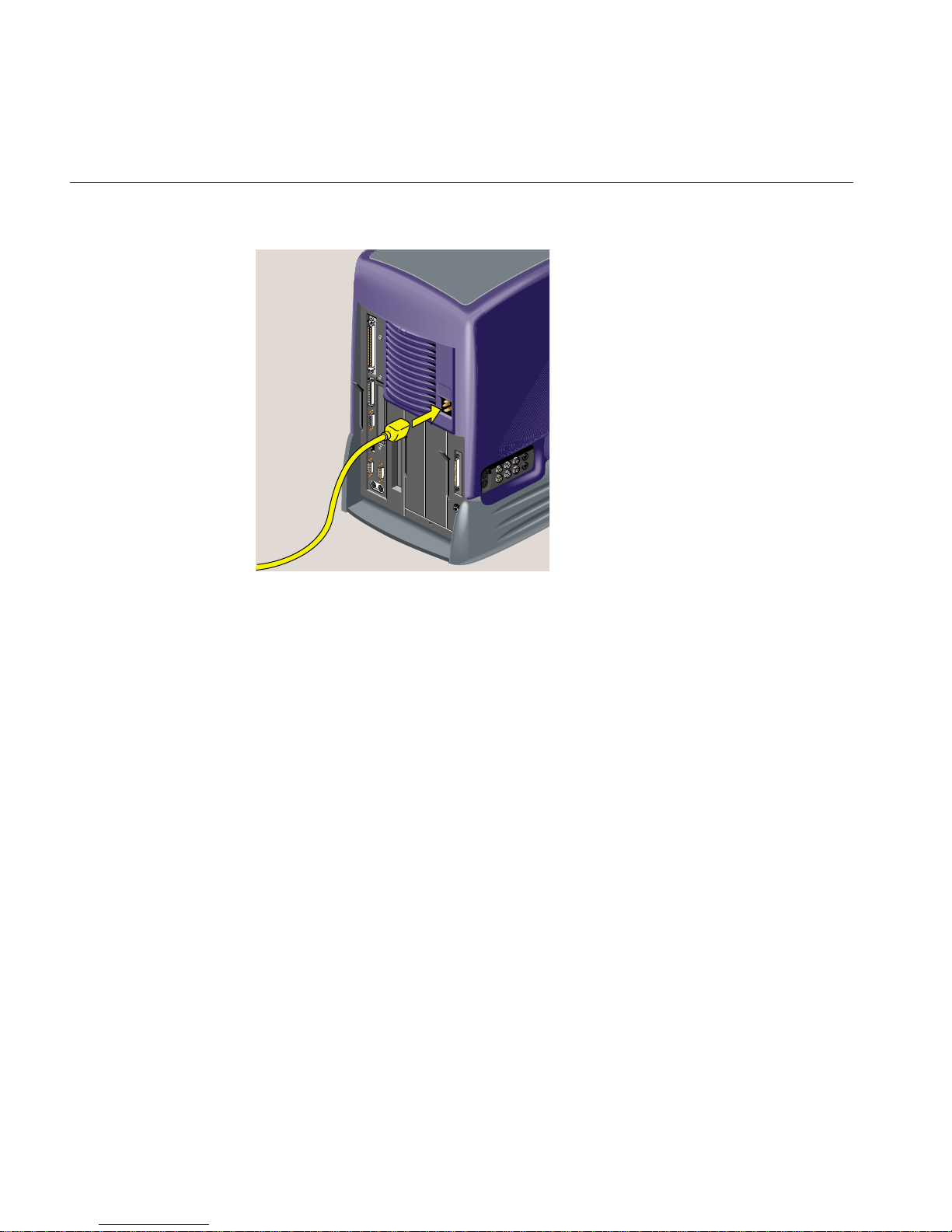
2. Connect the Ethernet 10-Base T or 100-Base T network cable to the Ethernet RJ45
connector on the rear of the workstation (Figure 1-7). If you do not have an Ethernet
connection in your office, check with your system administrator.
The O2+ workstation supports Ethernet 10-Base T and 100-Base T. For optional
networking PCI solutions supported on your workstation, contact your SGI service
provider.
007-4486-001 7
Page 28

Chapter 1: Getting Started
3. If you own an O2Cam, connect it to the workstation (Figure 1-7).
Figure 1-7 Connecting the Network Cable and the Camera to the Workstation
8 007-4486-001
Page 29

Setting Up the O2+ Workstation
4. Connect the monitor cable to the workstation and to the monitor (Figure 1-8).
(HD15)
1
R
G
1
(
H
D
1
5
)
B
2
(B
H
N
C
)
D
V
D
Figure 1-8 Connecting the Monitor to the Workstation
007-4486-001 9
Page 30

Chapter 1: Getting Started
5. Connect the power cables as follows (Figure 1-9).
• Connect one power cable to the monitor and to a working wall outlet.
• Connect the other power cable to the workstation and to a working wall outlet.
Caution: Always remove the power cable before removing the system module to
upgrade or replace parts.
!
CAUTION
Always disconnect
the power cable
before removing
the system module.
R
G
1
(
H
D
1
5
)
B
2
(B
H
N
C
)
D
V
D
Figure 1-9 Connecting the Power Cables to the Monitor and to the Workstation
10 007-4486-001
Page 31

6. Turn on the monitor and the workstation (Figure 1-10).
2
Setting Up the O2+ Workstation
1
Figure 1-10 Turning On the Monitor and the Workstation
Ergonomics Information
You can increase the comfort and safety of your work environment, and decrease your
chances of repetitive strain injuries, by following the human factors guidelines provided
in “Human Factors Guidelines for Setting Up Your O2+ Workstation” in Chapter 6.
007-4486-001 11
Page 32

Chapter 1: Getting Started
Registering Your Workstation
The Register&Win icon on your desktop or in your Applications Icon catalog provides
a quick and easy way to register your workstation online. You can return the information
via e-mail, the Internet, fax, or postal mail.
Registering your workstation ensures that you receive timely warranty coverage,
qualifies you for quarterly raffle prizes, and allows you to give SGI feedback.
Other Sources of Information
The printed Silicon Graphics O2+Workstation User’s Guide contains all the information you
need when your workstation is turned off and you cannot access online documentation.
Additional information such as a hardware overview with 3D animation, technical
specifications, cable pinout assignments, and regulatory statements are in this manual,
the Silicon Graphics O2+ Workstation Hardware Reference Guide.
This section provides information about five resources for obtaining other sources of
information, as follows:
• “IRIS InSight Document Library”
• “CD Installation”
• “Quick Answers”
• “InfoSearch”
• “SGI Technical Publications Library”
IRIS InSight Document Library
Online books are located in the IRIS InSight Document Library. From the Toolchest, select
Help > Online Books.
Figure 1-11 Insight Icon
12 007-4486-001
Page 33

CD Installation
Other Sources of Information
To locate the online version of this book, from the Toolchest on your desktop, select Help
> Online Books > SGI End User > Silicon Graphics O2+ Workstation Hardware Reference
Guide.
You can view the book online, or print the information you need. To print, select Print
from the Books menu in IRIS InSight.
If the online manual has been removed from your system disk, you can reinstall it from
the O2+ IRIX operating system CD that comes with upgrades. Follow these steps:
1. Place the “IRIX 6.5” CD in the CD-ROM drive and double-click the CD-ROM icon
on your desktop. The Software Manager window appears. Click the Dismiss
button.
2. Click Customize Installation.
3. When the Open Additional Distribution dialog box appears, click Done.
4. From the Selected menu, select Unmark All.
5. From the Selected menu, select Find.
6. When the dialog box appears, enter Hardware Reference Guide, and click Search.
Software Manager highlights the Silicon Graphics O2+ Workstation Hardware
Reference Guide in its Software Inventory window.
7. Click the Install check box to select the book for installation, and click Start to begin
the installation. When the installation is complete, you see this message:
“Installation and removals were successful. You may continue with installation or
quit now.” Click OK.
8. Exit Software Manager by selecting Exit from the File menu.
9. To locate the online books, from the Toolchest select Help > Online Books > SGI
End User > Silicon Graphics O2+ Workstation Hardware Reference Guide.
10. If the book does not appear on the End User Bookshelf, you may have to update the
InSight database. In a shell window (to become a super-user) at the prompt, enter:
su
(Also enter the root password if you are prompted for it.)
11. To update the InSight database, enter:
007-4486-001 13
Page 34

Chapter 1: Getting Started
Quick Answers
/usr/lib/infosearch/bin/booksAdmin -full -hwdi \
/usr/share/Insight/library/SGI_bookshelves
See “IRIS InSight Document Library” for instructions on viewing the book online.
Quick Answers provides quick answers about tasks and tools that are part of your
system’s end-user software environment. You will find answers in the form of short
“how to” descriptions, links that launch applications, and pointers to the information
you need.
To use Quick Answers, from the Toolchest, select Help > Quick Answers.
Figure 1-12 Toolchest
InfoSearch
InfoSearch lets you search or browse all online information on your desktop.
To use Infosearch, from the Toolchest, select Help > Infosearch.
SGI Technical Publications Library
If you have access to the Internet, you can view most manuals on the SGI Technical
Publications Library at http://techpubs.sgi.com/library
14 007-4486-001
Page 35

Turning the Workstation On or Off
To turn yourworkstation on or off, press the power button on the front(Figure 1-13). You
do not need to shut down the system software before turning it off.
Turning the Workstation On or Off
Figure 1-13 Turning the Workstation On or Off
You can also turn the workstation off from the Toolchest menu on the desktop, as follows:
1. From the Toolchest, select System > System Shutdown. If you have a root
password set, you are prompted to enter it.
2. As the system shuts down, you see a cautionary message warning you that all
running applications are stopped and remote users are logged off. Click OK to shut
down the system.
007-4486-001 15
Page 36

Chapter 1: Getting Started
3. You see a message that says the system is shutting down, and then another message
telling you it is okay to power off. You can then press and release the power button
on the front of the workstation. Or, to shut down and restart the system without
powering off, click Restart.
Figure 1-14 Power Off Message
Setting Up the O2Cam Digital Video Camera
Note: The O2Cam is not a standard item with O2+ workstations.
The O2Cam color digital video camera captures images and video recordings. It has a
built-in microphone that pointsin the same direction as the lens. When you record audio,
speak toward the front of the camera, not toward the microphone on the side.
Note: If you want to place the camera face down for snapshots of documents or objects
on the desktop, a desktop camera stand is available. To order one, contact your local SGI
service provider.
For information on software media tools that you can use with the camera, see “About
the Digital Media Tools User ’s Guide”.
For the camera’s technical specifications, see Hardware Central. (If your Web browser is
not loaded, it takes a few seconds to load.) Or, if you are viewing this on a remote server,
see “O2 Camera Technical Specifications” in Appendix A.
16 007-4486-001
Page 37

Setting Up the O2Cam Digital Video Camera
Figure 1-15 shows how to connect the O2Cam to the workstation. Connect the camera
before turning on workstation so that the system recognizes the device.
Figure 1-15 Connecting the O2Cam to the Workstation
007-4486-001 17
Page 38

Chapter 1: Getting Started
Figure 1-16 shows the features of the O2Cam.
Lens cover
Record button Focus ring
Tilt
hinge
LED activity
indicator
Directional
microphone
Figure 1-16 Front View of the O2Cam
18 007-4486-001
Page 39

Setting Up the O2Cam Digital Video Camera
Figure 1-17 shows how to use the microphone on the camera.
Figure 1-17 Using the O2Cam’s Built-in Microphone
007-4486-001 19
Page 40

Chapter 1: Getting Started
Figure 1-18 shows how to set up the O2Cam on your monitor.
Figure 1-18 Setting Up the O2Cam on Your Monitor
20 007-4486-001
Page 41

Securing the O2+ Workstation
Your workstation comes with a separate lockbar and a built-in slot for the Kensington
lock and cable. The lock and cable are not supplied bySGI. You purchase them separately
from a computer store. To secure the workstation, follow these steps:
1. Slide the feet of the lockbar into the holes on the rear of the workstation
(Figure 1-19).
Securing the O2+ Workstation
Figure 1-19 Attaching the Lockbar to the Workstation
007-4486-001 21
Page 42

Chapter 1: Getting Started
2. Slide the lockbar to the right (Figure 1-20).
Figure 1-20 Sliding the Lockbar
22 007-4486-001
Page 43

Locating Your Workstation’s Serial Number
3. Insert the Kensington lock into the built-in security connector on the workstation.
Push the key into the lock and turn it (Figure 1-21).
Figure 1-21 Locking the O2+ Workstation
Removing the Lockbar
To remove the lockbar, unlock and remove the security connector. Then slide the lockbar
to the left and lift it out.
Locating Your Workstation’s Serial Number
At times you may need to know your workstation’s serial number. This section lists
several ways that you can find it. The serial number is the one that begins with 08.
Note: The illustrations show an RM7000class workstation. The serial number is in the
same locations on an R12000class workstation.
007-4486-001 23
Page 44

Chapter 1: Getting Started
• On the rear of the workstation, the serial number is located on the bottom right
beneath the audio visual module (Figure 1-22).
Figure 1-22 Locating the Serial Number On the Rear
24 007-4486-001
Page 45

Locating Your Workstation’s Serial Number
• Inside the workstation, the serial number is on the connector of the PCI tray, which
is attached to the system module (Figure 1-23). (To remove the system module, see
“Removing the System Module” in Chapter 2).
Caution: The small, printed circuit board beneath the PCI tray contains a host chip
with important system information such as the serial number. Do not mix PCI trays
between workstations. To check if your workstation has its original PCI tray,
compare the serial number on the rear of the workstation with the serial number on
the PCI tray connector. The serial numbers should be the same.
Figure 1-23 Locating the Serial Number Inside the Workstation
• If your system is running, from a shell window, type:
sysinfo -vv
• From the Toolchest, select System > System Manager > About This System.
007-4486-001 25
Page 46

Page 47

Chapter 2
2. Installing or Removing Memory and Option Boards
This chapter explains how to install or remove DIMMs (double in-line memory
modules), PCI option boards, or a digital display option board. The following topics are
covered:
• “Removing the System Module”
• “Installing Memory Modules”
• “Removing Memory Modules”
• “Installing a PCI Board in an RM7000class Workstation”
• “Removing a PCI Board in an RM7000class Workstation”
• “Installing a PCI Board in an R12000class Workstation”
• “Removing a PCI Board in an R12000class Workstation”
• “Installing an Option Board”
• “Removing an Option Board”
• “Reinstalling the System Module”
• “Verifying the Hardware Installation”
Caution: Boards and DIMMs are extremely sensitive to static electricity. Handle the
!
boards carefully, and wear the wrist strap while installing the hardware.
Removing the System Module
Before installing memory or option boards, you must follow these steps:
007-4486-001 27
Page 48

Chapter 2: Installing or Removing Memory and Option Boards
Note: The illustrations show an O2+ RM7000class workstation. The process of installing
and removing the system module is the same for the O2+ R12000class workstation.
1. Turn off the workstation by pressing the power button on the front (Figure 2-1).
Figure 2-1 Turning Off the O2+ Workstation
2. Remove the power cable from the rear (Figure 2-2).
Caution: Always remove the power cable before removing the system module from
!
28 007-4486-001
the workstation.
When you walk quickly across a room, or sit down or stand up, you build up a lot of
static electricity. To perform any of the hardware tasks on the system module, you
should stand in one place until you have completed the task.
Page 49

Figure 2-2 Disconnecting the Power Cables
Removing the System Module
3. The system module is on the left as you face the rear. Pull down the lever on the left
side of the module to release it (Figure 2-3).
Note: You do not need to remove the cables from the system module, if you are
careful when handling it. But you may find it easier to work if the cables are
removed.
007-4486-001 29
Page 50

Chapter 2: Installing or Removing Memory and Option Boards
Figure 2-3 Pulling Down the Lever on the System Module
4. Slide the system module out of the chassis (Figure 2-4).
30 007-4486-001
Page 51

Figure 2-4 Remove the System Module from the Chassis
Removing the System Module
5. Lay the system module on a clean, flat surface, such as your desktop (Figure 2-5).
Figure 2-5 Laying the System Module on a Flat Surface
007-4486-001 31
Page 52

Chapter 2: Installing or Removing Memory and Option Boards
Now that you have removed the system module, you can perform the following
activities:
• To install memory, see “Installing Memory Modules.”
• To remove memory, see “Removing Memory Modules.”
• To install a PCI option board in an RM7000class workstation, see “Installing a PCI
Board in an RM7000class Workstation.”
• To remove a PCI option board in an RM7000class workstation, see “Removing a PCI
Board in an RM7000class Workstation.”
• To install a PCI option board in an R12000class workstation, see “Installing a PCI
Board in an R12000class Workstation.”
• To remove a PCI option board in an R12000class workstation, see “Removing the
PCI Tray in an R12000class Workstation.”
• To install a digital display option board, see “Installing an Option Board.”
• To remove a digital display option board, see “Removing an Option Board.”
Installing Memory Modules
To see a 3D animation of installing memory modules, see Hardware Central. When the
browser window opens, see “Hardware Overview” and then “Installing Memory
Modules.” (If your Web browser is not loaded, it takes a few seconds to load.) If you are
viewing this on a remote server, the 3D animation is not available.
Caution: The O2+ workstation uses DIMMs (Double Inline Memory Modules). DIMMs
!
32 007-4486-001
are extremely sensitive to static electricity. Handle the modules carefully, and wear the
wrist strap while installing them.
Note: The illustrations show an O2+ RM7000class workstation. The process of installing
and removing memory modules is the same for the O2+ R12000class workstation. Also
note that DIMMs cannot be installed on earlier workstations that used SIMMs.
Page 53

Installing Memory Modules
To install memory modules, follow these steps:
1. If you have not already done so, remove the power cable, and remove the system
module from the chassis. See “Removing the System Module.”
2. Components on the system module are extremely sensitive to static electricity.
Before touching any of the components, ground yourself to a metal part of the
chassis, as follows:
• Unwrap the first two folds of the wrist strap and wrap the exposed adhesive
side firmly around your wrist.
• Unroll the rest of the strap and peel the liner from the copper foil at the opposite
end.
• Attach the copper foil to the PCI tray. Attach the wrist strap to your wrist and to
the PCI tray (Figure 2-6).
Figure 2-6 Attaching the Wrist Strap
3. Familiarize yourself with the memory (DIMM) banks (Figure 2-7) and (Figure 2-8).
There are four banks comprised of eight sockets, numbered 1 through 8. Two
sockets form a bank.
The minimum configuration has 256 MB of memory—one 128-MB module installed
in slot 1 and one 128-MB module installed in slot 2.
007-4486-001 33
Page 54

Chapter 2: Installing or Removing Memory and Option Boards
Figure 2-7 Locating the DIMM Banks
DIMM banks
8
7
6
5
4
Banks
3
2
1
Figure 2-8 Top View of the DIMM Banks
4. Read the following guidelines and then proceed to the next step.
• Slots 1 and 2 must always be populated.
• High-density DIMMs must always be installed in the lowest slots, that is, slots 1
and 2.
34 007-4486-001
Page 55

Installing Memory Modules
• Install the DIMMs in groups of two, with DIMMs of the same capacity in each
bank of two. You cannot mix capacities in one bank.
• In a bank of two slots, both slots must have a DIMM or both slots must be
empty (except for slots 1 and 2, which must always be populated). For example,
you can install a 128-MB module in slot 3, a 128-MB module in slot 4, a 64-MB
module in slot 5 and a 64-MB module in slot 6. But you cannot install a 128-MB
module in slot 3 and a 64-MB module in slot 4.
Note: If you need to remove a DIMM, see “Removing Memory Modules.”
5. Install the DIMMs consecutively in groups of two, beginning with the lowest open
slot (Figure 2-9), as follows:
• Hold the DIMM over the socket without tilting it.
• Lower the DIMM, pushing it straight down into the socket gently but firmly.
You hear a click as it is seated and the latches on each side of the module snap
up.
Figure 2-9 Installing the Memory Modules
6. Check the DIMMs visually to make sure they are installed correctly (Figure 2-10), as
follows:
• The tops of the DIMMs of the same capacity should be even.
007-4486-001 35
Page 56

Chapter 2: Installing or Removing Memory and Option Boards
• The DIMMs should all be absolutely vertical (no leaning).
• The latches on the sides should fit snugly against each DIMM.
Figure 2-10 Checking the DIMM Installation
7. Remove the wrist strap and follow the steps in “Reinstalling the System Module.”
Removing Memory Modules
To remove memory modules, follow these steps:
1. If you have not already done so, remove the power cable, and remove the system
module from the chassis. See “Removing the System Module.”
2. Before touching any of the components, ground yourself to a metal part of the
chassis, as follows:
• Unwrap the first two folds of the wrist strap and wrap the exposed adhesive
side firmly around your wrist.
• Unroll the rest of the strap and peel the liner from the copper foil at the opposite
end.
• Attach the copper foil to the PCI tray. Attach the wrist strap to your wrist and to
the PCI tray (Figure 2-11).
36 007-4486-001
Page 57

Removing Memory Modules
Figure 2-11 Attaching the Wrist Strap
3. Remove the DIMM by pushing down the latches on both sides to release it. Pick up
the DIMM and set it aside (Figure 2-12).
Figure 2-12 Removing the Memory Module
4. If you want to install memory modules, see “Installing Memory Modules.” If not,
remove the wrist strap and follow the steps in “Reinstalling the System Module.”
007-4486-001 37
Page 58

Chapter 2: Installing or Removing Memory and Option Boards
Installing a PCI Board in an RM7000class Workstation
To install a PCI board in an RM7000class workstation, follow these steps:
Note: Check the documentation andsoftware release notes that comewith the PCI board
for instructions on installing the software. The software may include online software
guides.
1. If you have not already done so, remove the power cable, and remove the system
module from the chassis. (See “Removing the System Module.”)
Caution: The small, printed circuit board beneath the PCI tray contains a host chip
!
with important system information such as the serial number. Do not mix PCI trays
between workstations. If you remove the PCI tray, always replace it, or the
workstation will not operate correctly.
2. Release the PCI tray by pushing up the lever on the side (Figure 2-13). The tray pops
up.
Figure 2-13 Releasing the PCI Tray
3. Push down slightly on the rear of the PCI tray and remove it from the system
module (Figure 2-14).
38 007-4486-001
Page 59

Figure 2-14 Removing the PCI Tray
Installing a PCI Board in an RM7000class Workstation
4. Hold the PCI tray with one hand and remove the screw and the filler panel from the
tray (Figure 2-15). Keep the panel and screw. If you later remove the PCI board and
do not replace it, you must reinstall the filler panel.
007-4486-001 39
Page 60

Chapter 2: Installing or Removing Memory and Option Boards
Figure 2-15 Removing the Screw and Filler Panel
5. Slide the PCI board into the tray and push the PCI connector firmly into the slot
(Figure 2-16). Make sure it is completely seated. You should hear a click as it is
seated. You may have to use some pressure.
Note: PCI boards with extra long I/O connectors may be difficult to install. In this
case, slide the board into the tray at an angle, inserting the side with the I/O
connector first, and then rotate in the other side.
6. Replace the screw and tighten it (Figure 2-16).
40 007-4486-001
Page 61

Figure 2-16 Installing the PCI Board
Installing a PCI Board in an RM7000class Workstation
7. Push the lever to return it to its starting position (Figure 2-17).
007-4486-001 41
Page 62

Chapter 2: Installing or Removing Memory and Option Boards
Figure 2-17 Returning the Lever to Its Starting Position
8. Replace the tray in the system module (Figure 2-18), as follows:
• Engage the hinge on the PCI tray in the slot on the system module.
• Lower the tray, as you push toward the back of the system module.
• Look from the side and align the gold-colored PCI edge connector with the slot
on the system board.
42 007-4486-001
Page 63

Installing a PCI Board in an RM7000class Workstation
Figure 2-18 Replacing the PCI Tray in the System Module
9. Push the tray down firmly until it is completely seated. You hear a click as it seats.
Check that the lever returns to its starting position (Figure 2-19).
Caution: If the PCI tray is not completely seated, the system module will not slide
!
007-4486-001 43
back into the chassis.
Page 64

Chapter 2: Installing or Removing Memory and Option Boards
Figure 2-19 PCI Tray Seated Correctly
Note: If the option board you installed comes with a cable, remember to connect the
cable to the option board’s external port after you reinstall the system module.
10. Follow the steps in “Reinstalling the System Module.”
Removing a PCI Board in an RM7000class Workstation
To remove a PCI board in an RM7000class workstation, follow these steps:
1. If you have not already done so, remove the power cable and remove the system
module from the chassis. (See “Removing the System Module.”)
2. Release the PCI tray by pushing up the lever on the side (Figure 2-20). The tray pops
up.
44 007-4486-001
Page 65
Removing a PCI Board in an RM7000class Workstation
Figure 2-20 Releasing the PCI Tray
3. Push down slightly on the rear of the PCI tray and remove it from the system
module (Figure 2-21).
Figure 2-21 Removing the PCI Tray
4. Remove the screw that secures the board (Figure 2-22). Disconnect the PCI board
and slide it out of the tray. (It may be a little difficult to remove.)
007-4486-001 45
Page 66

Chapter 2: Installing or Removing Memory and Option Boards
Note: If the PCI board has an extra long I/O connector, pivot up the side of the board
without the long I/O connector first. Then slide out the side with the I/O connector.
Figure 2-22 Removing the Screw and the PCI Board
5. If you want to install another PCI board, see “Installing a PCI Board in an
RM7000class Workstation”. If not, replace the filler panel and screw (Figure 2-23).
(You removed the panel and screw when you installed the board.)
46 007-4486-001
Page 67

Installing a PCI Board in an R12000class Workstation
Figure 2-23 Replacing the Filler Panel and Screw on the PCI Tray
6. Follow the steps in “Reinstalling the System Module.”
Installing a PCI Board in an R12000class Workstation
To install a PCI board in an R12000class workstation, follow these steps:
Note: Check the documentation and software release notes that comes with the PCI
board for instructions on installing the software. The software may include online
software guides.
007-4486-001 47
Page 68
Chapter 2: Installing or Removing Memory and Option Boards
1. If you have not already done so, remove the power cable, and remove the system
module from the chassis. (See “Removing the System Module.”)
Caution: The small, printed circuit board beneath the PCI tray contains a host chip
!
with important system information such as the serial number. Do not mix PCI trays
between workstations. If you remove the PCI tray, always replace it, or the
workstation will not operate correctly.
2. Remove the screw and filler panel from the PCI tray.
Keep the panel. If you later remove the PCI board and do not replace it, you must
reinstall the filler panel and screw (Figure 2-24).
Figure 2-24 Removing the Screw and Filler Panel
Note: PCI boards with extra long I/O connectors may be difficult to install. In this case,
slide the board into the tray at an angle, inserting the side with the I/O connector first,
and then rotate in the other side.
3. Install the PCI board by sliding the PCI board into the tray and pushing the PCI
connector firmly into the slot. Make sure it is completely seated (Figure 2-25). You
may need to use some pressure to seat it all the way.
48 007-4486-001
Page 69

Installing a PCI Board in an R12000class Workstation
Figure 2-25 Installing the PCI Board on the R12000class Workstation
4. Insert and tighten the screw that secures the PCI board (Figure 2-26).
Figure 2-26 Securing the PCI Board
5. Follow the steps in “Reinstalling the System Module.”
007-4486-001 49
Page 70

Chapter 2: Installing or Removing Memory and Option Boards
Removing a PCI Board in an R12000class Workstation
To remove a PCI board in an R12000class workstation, follow these steps:
1. If you have not already done so, remove the power cable and remove the system
module from the chassis. (See “Removing the System Module.”)
2. Remove the screw that secures the PCI board (Figure 2-27).
3. Remove any external cables connected to the PCI board.
4. Disconnect the PCI board from the connector and slide it out of the tray. (It may be a
little difficult to remove.)
Note: If the PCI board has an extra long I/O connector, slide out the side opposite the
long I/O connector first. Then remove the side with the I/O connector.
Figure 2-27 Removing the Screw That Secures the PCI Board
5. If you want to install another PCI board, see “Installing a PCI Board in an
R12000class Workstation.” If not, replace the screw and filler panel (Figure 2-28).
(You removed the screw and panel when you first installed the board.)
50 007-4486-001
Page 71

Figure 2-28 Replacing the Filler Panel and Screw
6. Follow the steps in “Reinstalling the System Module.”
Installing an Option Board
Installing an Option Board
The figures in this section show an option board similar to the Dual Channel Display
Option Board (DCD), which enables two monitors to be plugged into an O2+
workstation (Figure 2-29).
The board you want to install may look different, but the installation steps are the same.
Review any documentation that comes with the option board.
Caution: Option boards are extremely sensitive to static electricity. Handle it carefully,
!
007-4486-001 51
and wear the wrist strap while installing the board.
Page 72

Chapter 2: Installing or Removing Memory and Option Boards
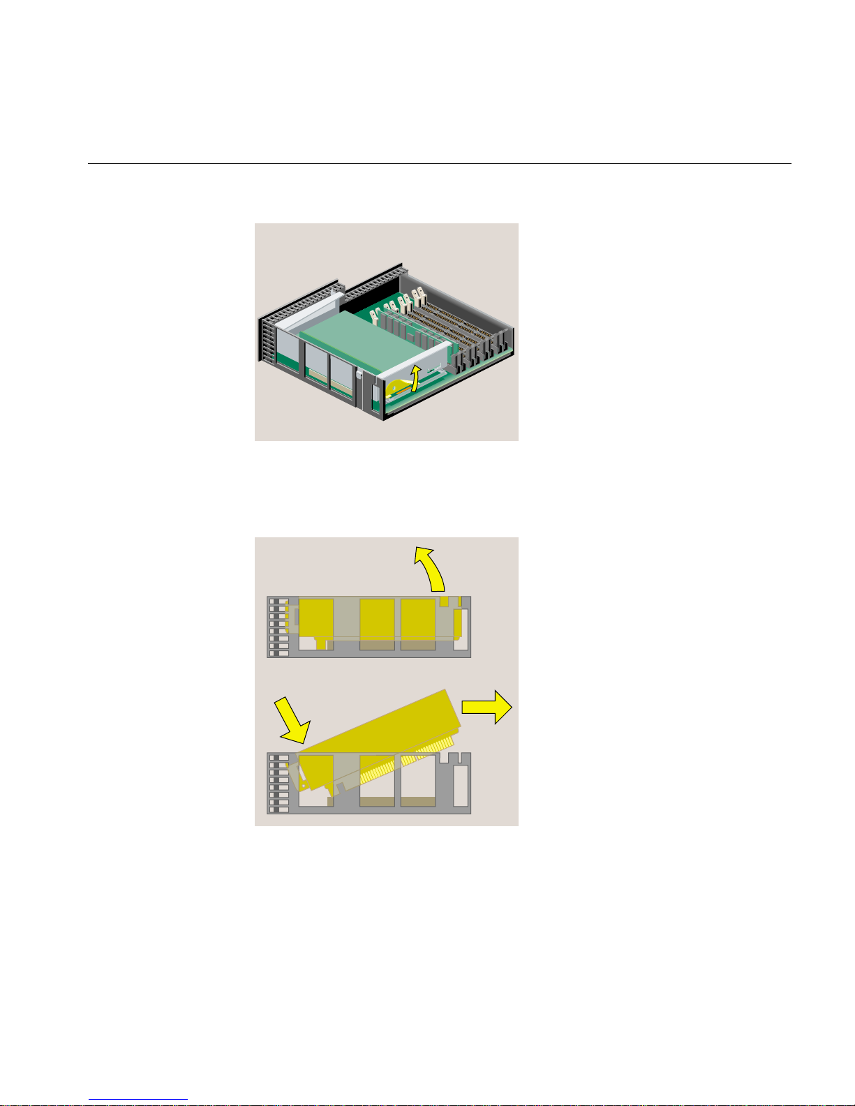
Figure 2-29 Option Board
The slot for the display option is on the system module.
To install an option board, follow these steps:
1. If you have not already done so, remove the power cable, and remove the system
module from the chassis. (See “Removing the System Module.”)
2. Remove the PCI tray as follows:
• If you have an RM7000class workstation, see “Removing a PCI Board in an
RM7000class Workstation.”
• If you have an R12000class workstation, see “Removing the PCI Tray in an
R12000class Workstation.”
Note: Most of the illustrations in this section show an RM7000class workstation. The
installation process is the same for an R12000class workstation.
3. Before touching any of the components, ground yourself to a metal part of the
chassis with a wrist strap (Figure 2-30), as follows:
• Wrap the first two folds of the strap around your wrist.
52 007-4486-001
Page 73
• Peel the liner from the copper foil at the opposite end.
• Attach the copper foil to the metal part of the chassis.
Installing an Option Board
Figure 2-30 Attaching the Wrist Strap
4. If there is a filler panel covering the I/O slot, remove the filler panel as follows:
• Use a Phillips screwdriver to remove the two screws that hold it (Figure 2-31).
• Push the filler panel inward.
• Remove the filler panel and save it. In the event that you remove the option
board and do not replace it, you must reinstall the panel.
007-4486-001 53
Page 74

Chapter 2: Installing or Removing Memory and Option Boards
Figure 2-31 Removing the I/O Filler Panel
5. Maneuver the board until its I/O connector is opposite the open slot in the rear of
the chassis and it is parallel to the system board (Figure 2-32). You may find this
installation difficult, especially on an R12000class workstation, because there is
limited space in which to work. Figure 2-32, Figure 2-33, and Figure 2-34 show an
R12000class O2+ workstation.
54 007-4486-001
Page 75

Installing an Option Board
Figure 2-32 Positioning the Option Board
6. Push the left side of the board toward the rear and then to the right side, until the
connector underneath is aligned over the socket on the system board. Remember to
keep the board parallel to the system board as you align it (Figure 2-33).
1
Figure 2-33 Aligning the Option Board
007-4486-001 55
2
Page 76

Chapter 2: Installing or Removing Memory and Option Boards
7. Push the board down into the socket firmly until it clicks and the connectors are
completely seated. Look from the side as shown in Figure 2-34.
Figure 2-34 Seating the Option Board Viewed from the Side
8. Insert and tighten two screws in the locations shown (Figure 2-35).
Figure 2-35 Installing the Two Screws
56 007-4486-001
Page 77

9. Remove the wrist strap.
10. Reinstall the PCI tray as follows:
• If you have an RM7000class workstation, see “Reinstalling the PCI Tray in an
RM7000class Workstation.”
• If you have an R12000class workstation, see “Reinstalling the PCI Tray in an
R12000class Workstation.”
Removing the PCI Tray in an RM7000class Workstation
To remove the PCI tray in an RM7000class workstation, follow these steps:
1. Push up the lever on the side of the PCI tray to release it (Figure 2-36). The tray pops
up.
Installing an Option Board
Figure 2-36 Releasing the PCI Tray
2. Push down slightly on the rear of the PCI tray and remove it from the system
module (Figure 2-37). Do not remove the PCI board from the tray, if one is installed.
007-4486-001 57
Page 78

Chapter 2: Installing or Removing Memory and Option Boards
Figure 2-37 Removing the PCI Tray
3. Follow the steps in “Installing an Option Board.”
Removing the PCI Tray in an R12000class Workstation
To remove the PCI tray in an R12000class workstation, follow these steps:
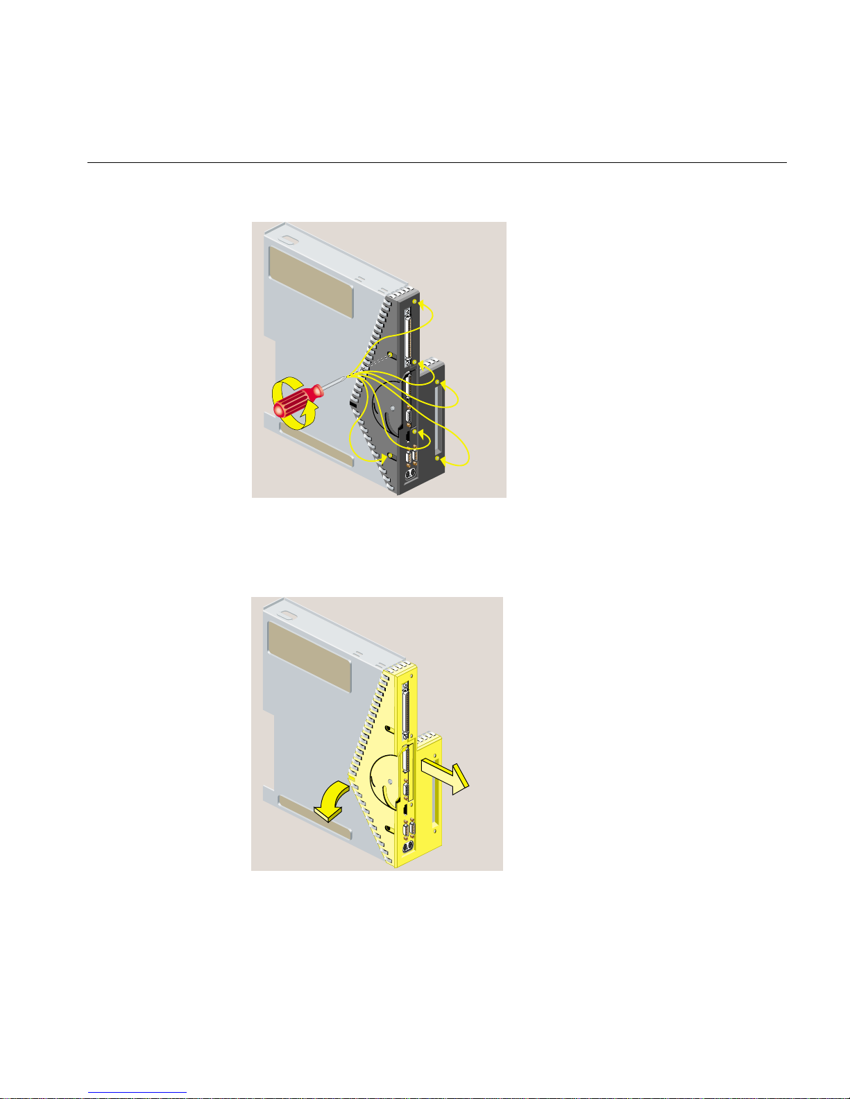
1. You must remove the plastic faceplate of the system module as follows:
• Use a Phillips screwdriver to remove five screws in the rear and two screws on
the underside, in the locations shown (Figure 2-38). Keep the two screws from
the underside separate. When reinstalling the faceplate you must use the same
screws.
Caution: On the underside, remove only two screws. Do not remove the third
!
58 007-4486-001
screw that attaches the lever to the faceplate.
Page 79
Installing an Option Board
Figure 2-38 Removing the Screws from the Faceplate
• Remove the faceplate by grasping it where the plastic comes to a “V” and
pulling it outward. (See Figure 2-39.) The filler panel covering the I/O port falls
away as you remove the faceplate.
Figure 2-39 Removing the Faceplate from the System Module
007-4486-001 59
Page 80

Chapter 2: Installing or Removing Memory and Option Boards
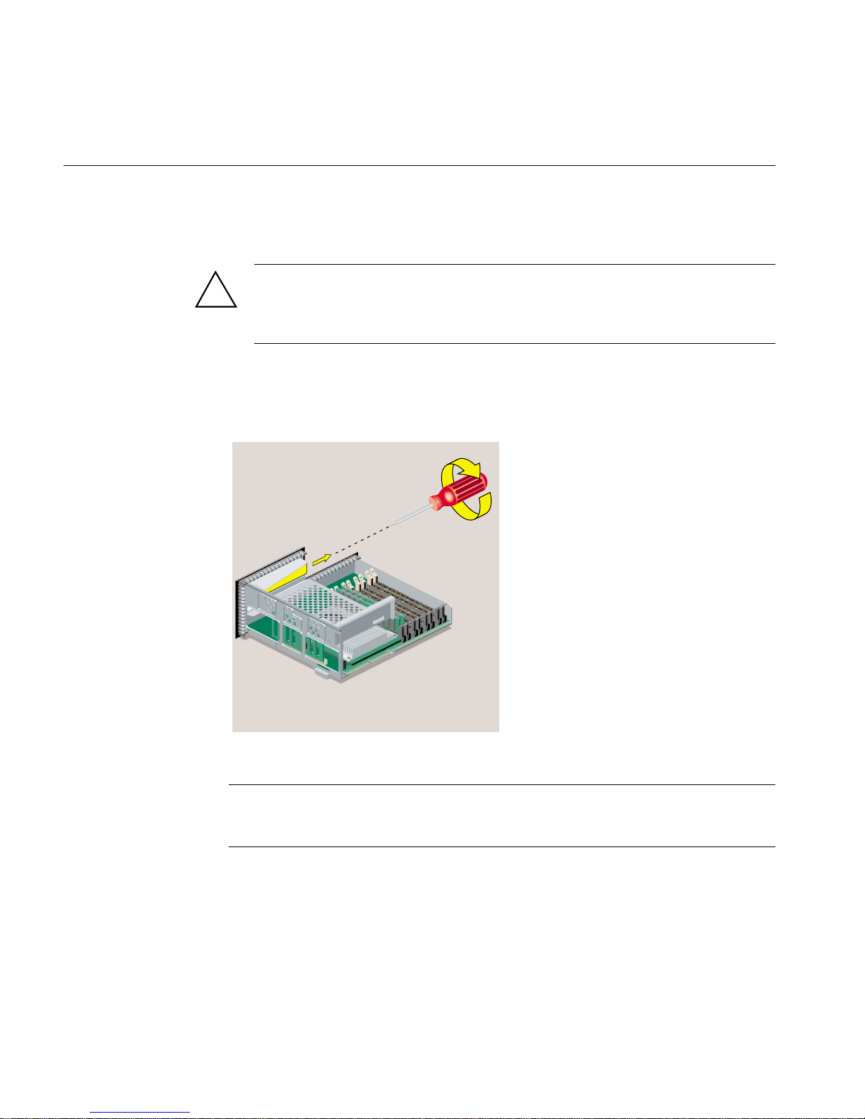
2. Remove the PCI tray from the system module, as follows. If a PCI board is installed in
the tray, do not remove it from the tray. However, you need to disconnect any cables
attached to the PCI board.
• Insert a screwdriver in the small opening shown (Figure 2-40). Use a twisting
motion first to release the PCI connector from the slot on the system module.
Then use an up and down motion to release the PCI tray.
• Pull the PCI tray straight up to remove it and set it aside.
Figure 2-40 Removing the PCI Tray from the R12000class System Module
3. Follow the steps in “Installing an Option Board.”
Reinstalling the PCI Tray in an RM7000class Workstation
To reinstall the PCI tray in an RM7000class workstation, follow these steps:
60 007-4486-001
Page 81

Installing an Option Board
1. Push the lever to return it to its starting position (Figure 2-41).
Figure 2-41 Returning the Lever to Its Starting Position
2. Reinstall the PCI tray in the system module (Figure 2-42), as follows:
• Engage the hinge on the PCI tray in the slot on the system module.
• Lower the tray as you push toward the back of the module.
• Align the gold-colored PCI edge connector with the slot on the system board.
007-4486-001 61
Page 82

Chapter 2: Installing or Removing Memory and Option Boards
Figure 2-42 Replacing the PCI Tray in the System Module
3. Push the tray down firmly until it is completely seated. You hear a click as it seats
(Figure 2-43).
Caution: If the PCI tray is not completely seated, the system module will not slide
!
62 007-4486-001
back into the chassis.
Page 83

Figure 2-43 PCI Tray Seated Correctly
4. Follow the steps in “Reinstalling the System Module.”
Installing an Option Board
Reinstalling the PCI Tray in an R12000class Workstation
To reinstall the PCI tray in an R12000class workstation, follow these steps:
1. Replace the PCI tray in the system module, as follows:
• Lower the PCI tray, engaging it on the tab on the side of the system module
(Figure 2-44).
• Insert the PCI connector beneath the tray into the slot on the system module.
• Once the connector is aligned, push down firmly until it is completely seated.
Note: If the PCI tray is not completely seated, the system module will not slide back
into the chassis.
007-4486-001 63
Page 84

Chapter 2: Installing or Removing Memory and Option Boards
Figure 2-44 Replacing the R12000class PCI Tray in the System Module
2. Replace the faceplate by sliding it onto the system module, while at the same time
lifting the plastic at the “V” to snap it in place. When properly seated, the underside
of the faceplate is flush to the module and the screw holes are aligned (Figure 2-45).
64 007-4486-001
Page 85

Installing an Option Board
Figure 2-45 Replacing the Faceplate
3. Align the screw holes on the faceplate with the screw holes on the system module.
Use a Phillips screwdriver to insert and tighten two screws on the underside in the
locations shown (Figure 2-46).
Figure 2-46 Replacing Two Screws on the Faceplate
007-4486-001 65
Page 86

Chapter 2: Installing or Removing Memory and Option Boards
4. Use a Phillips screwdriver to insert and tighten five screws on the rear in the
locations shown (Figure 2-47).
Figure 2-47 Replacing Five Screws on the Faceplate
5. Follow the steps in “Reinstalling the System Module.”
Removing an Option Board
To remove an option board, follow these steps:
1. If you have not already done so, remove the power cable, and remove the system
module from the chassis. (See “Removing the System Module.”)
2. To reach the option board, you must first remove the PCI tray, as follows:
• If you have an RM7000class workstation, see “Removing a PCI Board in an
RM7000class Workstation.”
• If you have an R12000class workstation, see “Removing the PCI Tray in an
R12000class Workstation.”
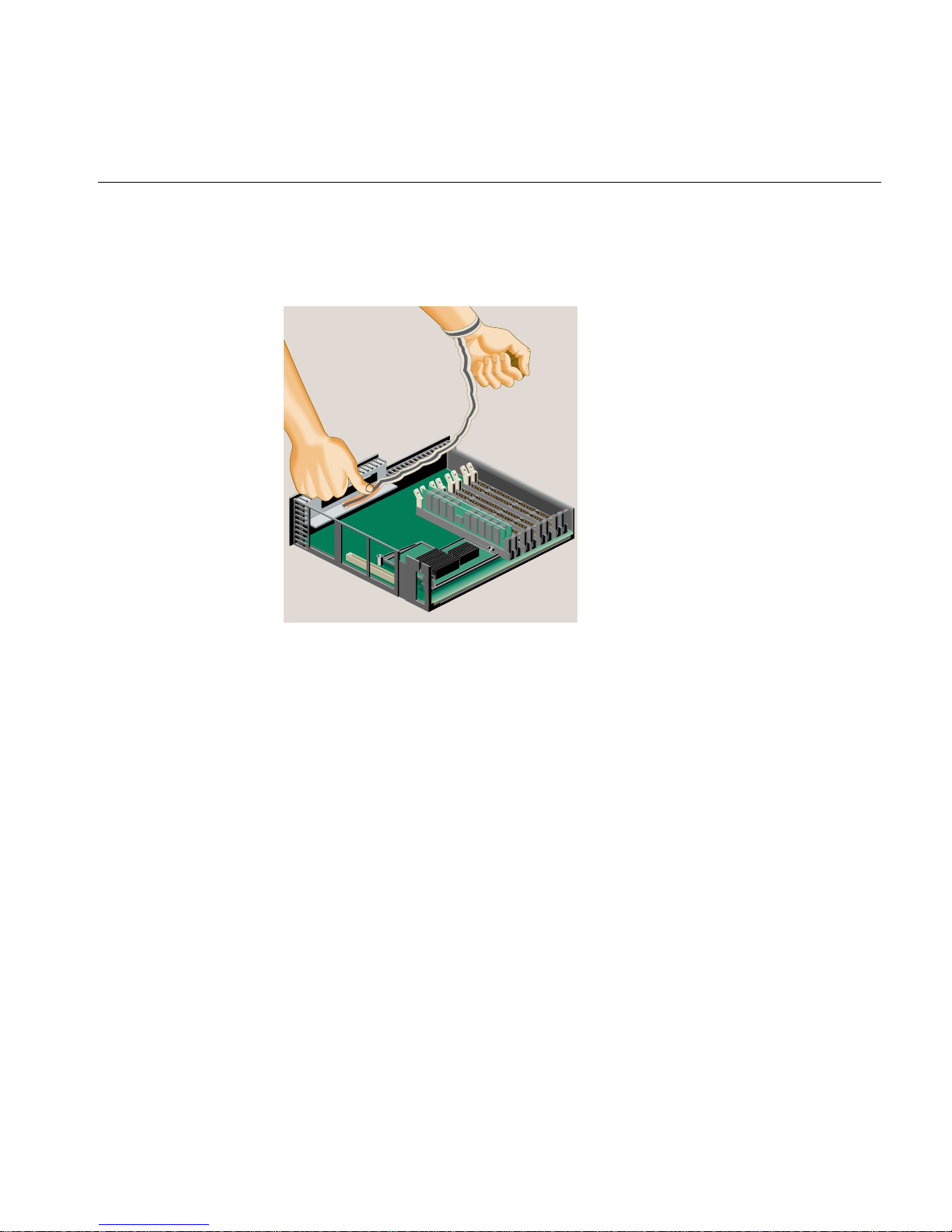
3. Before touching any of the components, ground yourself to a metal part of the
chassis with a wrist strap (Figure 2-48), as follows:
• Wrap the first two folds of the strap around your wrist.
66 007-4486-001
Page 87

• Peel the liner from the copper foil at the opposite end.
• Attach the copper foil to the metal part of the chassis.
Removing an Option Board
Figure 2-48 Attaching the Wrist Strap
4. Grasp the board on either side and gently rock it out until it disconnects from the
slot on the system board (Figure 2-49). Do not exaggerate the rocking motion,
because you should not bend the pins. You may find this difficult because there is
limited space in which to work.
007-4486-001 67
Page 88

Chapter 2: Installing or Removing Memory and Option Boards
Figure 2-49 Removing the Option Board
5. If you want to install another option board, see “Installing an Option Board.” If not,
replace the filler panel that you removed when you installed the first option board.
6. Remove the wrist strap.
7. Reinstall the PCI tray, as follows:
• If you have an RM7000class workstation, see “Reinstalling the PCI Tray in an
RM7000class Workstation.”
• If you have an R12000class workstation, see “Reinstalling the PCI Tray in an
R12000class Workstation.”
68 007-4486-001
Page 89

Reinstalling the System Module
To reinstall the system module, follow these steps:
Note: The illustrations show an RM7000class workstation. The process of installing the
system module is the same for an R12000class workstation.
1. Return the system module to its upright position (Figure 2-50).
Reinstalling the System Module
Figure 2-50 Returning the System Module to Its Upright Position
2. Slide the system module into the chassis until the lever engages (Figure 2-51).
007-4486-001 69
Page 90

Chapter 2: Installing or Removing Memory and Option Boards
Figure 2-51 Reinstalling the System Module in the Chassis
3. Push the lever up to lock the module in place (Figure 2-52). If installed correctly, the
lever is all the way up and the system module is flush with the system drive module
and other modules.
70 007-4486-001
Page 91

Figure 2-52 Securing the System Module in Place
Reinstalling the System Module
4. Remove the wrist strap from the chassis.
5. Reconnect the power cable and any other cables you removed (Figure 2-53).
6. If you installed an option board that has a cable, connect the cable to the I/O port on
the board you installed.
007-4486-001 71
Page 92
Chapter 2: Installing or Removing Memory and Option Boards
Figure 2-53 Connecting the Power Cable
7. Turn on the workstation by pressing the power button on the front (Figure 2-54).
8. If you have just installed memory modules or an option board, follow the steps in
“Verifying the Hardware Installation.”
72 007-4486-001
Page 93

Figure 2-54 Turning On the Workstation
Verifying the Hardware Installation
Verifying the Hardware Installation
Once you have installed memory modules or an option board, you should verify that the
system recognizes the new hardware, as follows:
1. Log in to your account.
2. From the Toolchest (Figure 2-55), select System > System Manager > About This
System.
Figure 2-55 The Toolchest
007-4486-001 73
Page 94

Chapter 2: Installing or Removing Memory and Option Boards
3. If you installed memory, look under the Hardware menu. Check the amount of
memory shown. It should equal the total amount that you installed.
For example, if you had 32 MB of memory when you started and you installed
another 64 MB, the total shown should be 96 MB.
If the system does not show the total amount of memory you installed, turn off the
workstation, remove the power cable, remove the system module, and make sure
all the DIMMs are installed correctly.
4. If you installed a PCI option board, from a shell window, enter:
hinv
This shows the hardware inventory for your workstation. Look for a line describing
the board you installed. For some option boards, the software must be installed
before the board is shown.
If it is now shown, turn off the workstation, and review the installation steps again
to make sure the board is seated correctly. (See “Installing a PCI Board in an
RM7000class Workstation,” or “Installing a PCI Board in an R12000class
Workstation.”)
74 007-4486-001
Page 95

Chapter 3
3. Installing or Removing Peripherals
This chapter tells you how to install or remove a second hard disk drive in your O2+
workstation and how to connect external peripherals. The following topics are covered:
• “Installing a Second Internal Hard Drive in an RM7000class Workstation”
• “Removing the Second Internal Hard Drive in an RM7000class workstation”
• “Connecting External SCSI Devices”
• “Connecting Serial Devices”
• “Connecting Audio and Video Devices”
Installing a Second Internal Hard Drive in an RM7000class Workstation
Note: The optional drive bay is not available on O2+ R12000class workstations.
After you have installed the second hard disk, see “Setting Up a New Hard Disk” in the
online Personal System Administration Guide for information on how to manage your disk
space.
007-4486-001 75
Page 96

Chapter 3: Installing or Removing Peripherals
1. Turn off the workstation by pressing the power button on the front (Figure 3-1).
Figure 3-1 Turning Off the Workstation
2. Locate the optional drive bay (Figure 3-2) where you will install the second internal
hard drive. The drive bay is covered with a blank panel that you must remove.
76 007-4486-001
Page 97

Installing a Second Internal Hard Drive in an RM7000class Workstation
Figure 3-2 Locating the Optional Drive Bay
3. To remove the panel over the optional drive bay, you must first remove the
audio-visual module located on the far right as you face the rear of the workstation.
First, remove the power cable from the rear and any audio-visual cables that are
connected to the side panel (Figure 3-3).
007-4486-001 77
Page 98

Chapter 3: Installing or Removing Peripherals
Figure 3-3 Disconnecting the Power Cable and Other Cables
4. Release the audio-visual module by pulling down the lever (Figure 3-4).
78 007-4486-001
Page 99

Installing a Second Internal Hard Drive in an RM7000class Workstation
Figure 3-4 Releasing the Audio-visual Module
5. Slide the audio-visual module out of the chassis and place it carefully on a clean,
flat, antistatic surface, such as your desktop (Figure 3-5).
007-4486-001 79
Page 100

Chapter 3: Installing or Removing Peripherals
Figure 3-5 Sliding Out the Audio-visual Module
6. With your fingers, pry off the front panel that covers the optional drive bay
(Figure 3-6).
Save the panel. If you remove the second drive and do not replace it, you must
reinstall the panel.
80 007-4486-001
 Loading...