

Page 1

IRIS Workstation Guide
Version 1.0
Silicon Graphics, Inc.
Mountain View
California 94043
Page 2

Documentation:
Daniel Sears
Marcia Allen
Robin Bristow
Diane Wilford
Drawings:
Annette Whelan
©
Copyright 1984, Silicon Graphics, Inc.
This document contains proprietary information of
Silicon Graphics, Inc., and is protected by Federal
copyright law. The information may not be
disclosed to third parties or copied or duplicated in
any form, in whole or in part, without prior written
consent of Silicon Graphics, Inc.
IRIS Workstation Guide Version 1.0
Document Number: 5001-092-001-0
Page 3

CONTENTS
1. Introduction 1
2. Unpacking the IRIS Workstation Components 3
3. IRIS Workstation Specifications 5
3.1 Hardware Components 5
3.2 Ethernet Equipment 5
3.3 Cables 7
3.4 Monitor 7
IRIS Control Panel 7
Monitor Control Panel 9
Monitor Back Panel 9
3.5 Cabinet 11
Power Switch 11
Cabinet I/O Panel 11
Cabinet Power Panel 13
Power Switch 13
3.6 Documentation 13
4. Hardware Installation 15
4.1 Keyboard to Monitor Connection 15
4.2 Mouse to Monitor Connection 15
4.3 Monitor to Cabinet Video Connections 15
4.4 Monitor to Cabinet Control Cable Connection 17
4.5 Monitor to Cabinet AC Power Cable Connection 17
4.6 IRIS Workstation to Serial Line Connection 17
Terminal Connection 17
Modem Connection 18
Printer Connection 18
4.7 IRIS Workstation to Ethernet Connection 18
4.8 Cabinet AC Power Connection 19
4.9 Cabinet to Dial and Switch Box Connection 19
5. Operation 21
5.1 Boot 21
5.2 Demonstration Programs 22
5.3 Monitor Adjustment 23
5.4 Network Software 24
5.6 Shutdown 25
6. System Administration 27
6.1 Startup 27
Automatic Disk Drive Boot 27
Automatic Tape Drive Boot 28
PROM Monitor 28
6.2 Boot Checkout Information 29
- i -
Page 4

6.3 UNIX Single-User Mode 29
File Systems and fsck(1M) 32
6.4 Configuring UNIX on an IRIS Workstation 32
6.5 Configuration Files 32
6.6 Naming an IRIS Workstation 34
6.7 Adding a New Account 34
6.8 Connecting an ASCII Terminal to the IRIS Workstation 36
6.9 Connecting a Modem to the IRIS Workstation 38
6.10 Connecting a Printer to the IRIS Workstation 39
6.11 Enabling a Network Connection to the IRIS Workstation 40
6.12 Tape Drive 41
6.13 Shutdown 41
6.14 Crash Recovery 42
Appendix A: Configuration Switches 45
Appendix B: Fs c k - The Un i x File System Check Program 1 47
Appendix C: Diagnostics 71
Appendix D: The C/FORTRAN Interface 75
Appendix E: IRIS Floating Point 89
Appendix F: Manual Pages 99
Appendix H: IRIS Workstation RS-232 Interface 127
Appendix I: UUCP Administration 131
Appendix J: OEM Kernel Generation for the IRIS Workstation 141
Appendix K: The IRIS Terminal Programming Environment 147
Appendix L: GL 1 and GL 1.9 Software Differences 155
- ii -
Page 5
1. Introduction
This document explains how to install, test and operate an IRIS Workstation.
It contains step-by-step procedures for installing the components that make up
an IRIS Workstation. This document should be read carefully before installing
an IRIS Workstation.
The IRIS Workstation components are delivered assembled and ready for
connection with cables provided in the delivery cartons. The basic outline of
the installation is as follows:
•PlanningandSiteSelection
• UnpackingtheIRISWorkstationComponents
•HardwareInstallation
•OperationandTesting
Silicon Graphics provides a comprehensive product support and maintenance
program for the IRIS Workstation. For further information, the toll-free
Geometry Hotline numbers for Silicon Graphics Customer Service are:
Silicon Graphics Customer Service
(800) 252-0222 North America (except California)
(800) 345-0222 California
Version 1.0
Page 6

2 IRIS WORKSTATION GUIDE
Version 1.0
Introduction
Page 7

2. Unpacking the IRIS Workstation Components
The IRIS Workstation system is shipped in two reinforced cardboard cartons.
One contains the Electronics Cabinet and the other contains the Monitor and
other components. Each component is delivered assembled and ready for
connection with the cables provided in the IRIS Workstation delivery cartons.
If additional equipment or spare parts are ordered, they will be shipped in
additional cartons.
Before installation, the delivery cartons should be inspected for damage. If any
of the cartons or their contents appear damaged, contact the carrier and Silicon
Graphics Customer Service (see Section 1). After inspection, move the cartons
to the installation site. See Table 2-1 for a list of guidelines for site selection.
Although site selection is the customer’s responsibility, Silicon Graphics
representatives will provide consulting services upon request.
1. Inspect the delivery cartons for damage.
WARNING: The delivery cartons should be moved on a pallet jack
or cart capable of supporting 200 lbs. If they must be lifted, two
strong people are needed.
WARNING: Do not turn the delivery cartons on edge.
2. Move the cartons to the installation site.
3. Cut the plastic straps on the brown carton.
4. Cut the tape that seals the top of the carton, open the carton and
remove the tray containing the Keyboard, Mouse, cables and other
equipment.
5. Remove the foam spacers covering the Monitor.
6. Remove the carton by lifting it up and off the base pallet.
7. The Monitor is shipped inside a large plastic bag. Remove the
Monitor from the bag and place it on the table where it will be used.
WARNING: Do not attempt to pick up the Monitor by the white
plastic inserts on the sides.
8. Check for damage to the Monitor.
Version 1.0
Page 8

4 IRIS WORKSTATION GUIDE
Version 1.0
Unpacking the IRIS Workstation Components
Category IRIS 1400
Temperature 50 — 86F° (operating)
40 — 176F° (non-operating)
Relative humidity 40 — 80%
Minimum clearance 3” all sides
Monitor desk space 36” width
30” length
Cabinet floor space 24” width
33” length
29” height
Power 115 volts
15 amps
60 hertz
single phase
two wires + ground
Power consumption 883 watts
1240 KVA
Heat dissipation 3012 BTU/hour
Card slots 20
Table 2-1: IRIS Workstation Environmental Specifications
9. Compare the equipment included in the tray with the list in Section
3. If any parts appear to be missing, contact Silicon Graphics
Customer Service (see Section 1).
10. Cut the plastic straps on the white carton.
11. Open the top of the carton and remove the foam cap.
12. Lift the carton off of the Cabinet.
13. Lift the Cabinet off the base pallet and set it on the floor.
14. Remove the foam spacers.
15. The Cabinet is shipped inside a large plastic bag. Remove the
Cabinet from the bag.
16. Check for damage to the Cabinet.
17. Remove the front panel from the Cabinet and check that the boards
inside are firmly attached.
18. The Cabinet has four castors on its base that allow it to be rolled
across a surface. Roll it to the location where it will be used.
Page 9
3. IRIS Workstation Specications
Component Height Width Length Weight
IRIS 1400 Cabinet
Monitor
Keyboard
Mouse
Transceiver
29.0”
18.0”
1.5”
1.0”
2.0”
18.0”
20.0”
19.0”
2.0”
7.0”
27.0”
21.0”
8.5”
3.0”
4.0”
200.0 lbs
97.0 lbs
5.0 lbs
0.5 lbs
0.8 lbs
Table 3-1: IRIS Workstation Component Specifications
3.1 Hardware Components
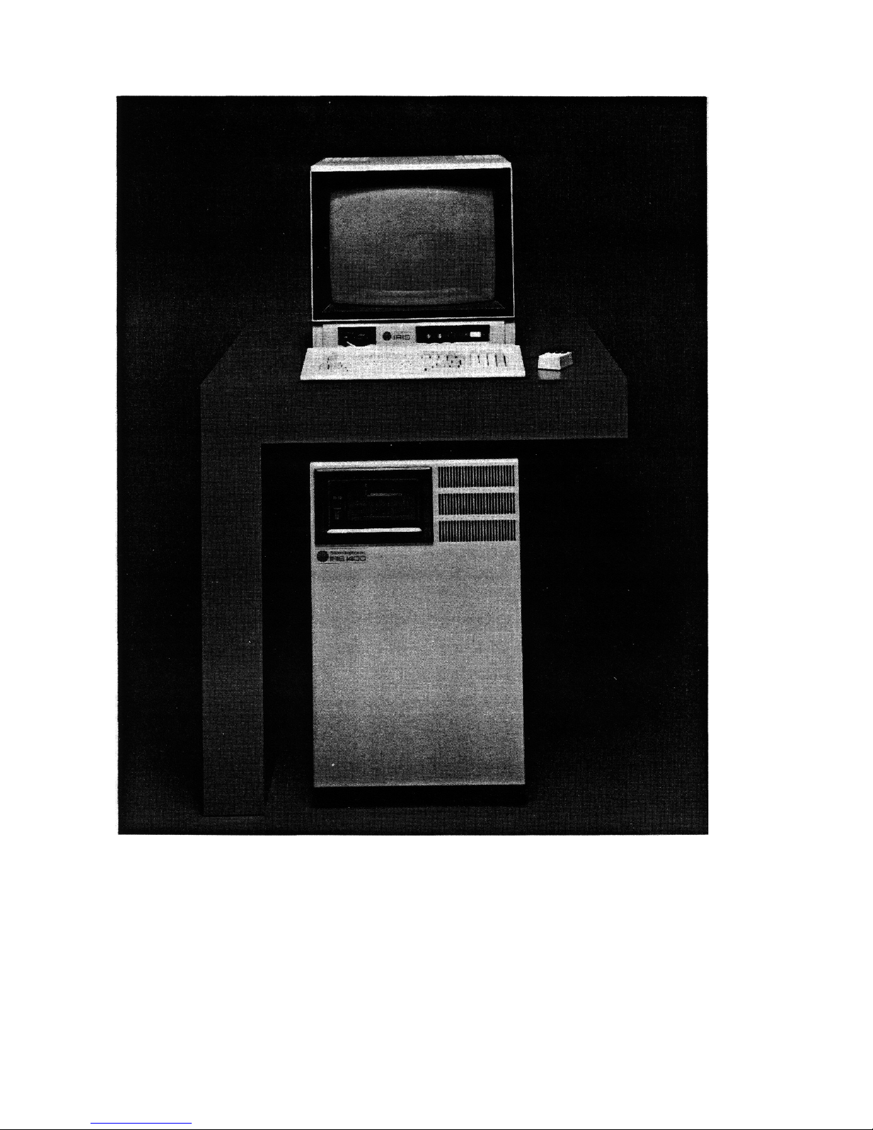
Each IRIS Workstation system has four hardware components (see Figure 3-1).
•TheElectronics Cabinet is a floor-standing unit with a 20-slot backplane
and a power supply. The Cabinet uses forced air cooling and is
mounted on casters.
•TheMonitor is a high-resolution 19-inch color monitor.
•TheKeyboard is an 83-key up-down encoded keyboard.
•TheMouse is a 3-button mouse.
•TheSwitch Box has 32 independently programmable switches and 32
independently programmable LED indicator lights. An 8 character
LED display gives status information for the Dial Box and the
Switch Box.
•TheDial Box (optional) has 8 independently programmable valuators
for sending analog information to an application program for the
IRIS Terminal.
3.2 Ethernet Equipment
The IRIS Workstation can be connected to an Ethernet local area network with
an Ethernet transceiver and drop cable.
•The Ethernet Transceiver connects the IRIS Workstation to the
Ethernet.
Version 1.0
Page 10
6 IRIS WORKSTATION GUIDE
Version 1.0
IRIS Workstation Specications
Figure 3-1: IRIS Workstation System
Page 11
Version 1.0
IRIS WORKSTATION GUIDE 7 IRIS Workstation Specications
•1 15-conductor drop cable connects the Cabinet to an Ethernet
transceiver.
3.3 Cables
Each IRIS Workstation is supplied with a cable set for connecting the IRIS
Workstation components.
•4 bundled, color-coded, coaxial video cables connect the video
output of the Cabinet to the Monitor.
• 1 25-conductor control cable connects the Cabinet to the Monitor.
This cable sends and receives signals between the Cabinet and the
Mouse, Keyboard and
Reset
button on the IRIS Control Panel.
• 210-foot,3-wire,groundedACpowercablesprovidepowerforthe
Monitor and Cabinet.
•137-pinflatcableconnectstheDialBoxtotheSwitchBox.
•19-pincableconnectstheSwitchBoxto
Port 4
on the Cabinet I/O
Panel.
•13-wireAC powercableprovidespowerforthe Dial Box andthe
Switch Box.
3.4 Monitor
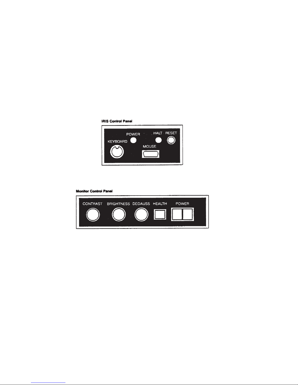
The Monitor has two control panels, the IRIS Control Panel on the front left
and the Monitor Control Panel on the front right. On the back of the Monitor
are several ports for receiving video signals, a power socket and a control cable
port.
IRIS Control Panel
The IRIS Control Panel has two ports for connecting the Keyboard and Mouse
to the Monitor, a
Reset
button and two indicator lights (see Figure 3-2).
•1DINsocketlabeled
Keyboard
is a port for connecting the Keyboard
to the Monitor.
•1slide-lockingDsocketlabeled
Mouse
is a port for connecting the
Mouse to the Monitor.
•1LEDlabeled
Power
indicates that power for the Cabinet is switched
on.
•1LEDlabeled
Halt
indicates that the processor is stopped.
•1
Reset
button is located on the IRIS Control Panel. Pressing this
button resets the processor which in turn resets the rest of the
system. After the
Reset
button has been pressed, the IRIS
Page 12
8 IRIS WORKSTATION GUIDE
Version 1.0
IRIS Workstation Specications
Figure 3-2: IRIS Control Panel and Monitor Control Panel
Page 13
Version 1.0
IRIS WORKSTATION GUIDE 9 IRIS Workstation Specications
Workstation must be rebooted. This switch and the
Halt
light
correspond to the
Reset
button and
Halt
light on the I/O Control
Panel on the Cabinet. Either button may be used.
WARNING: Do not press the
Reset
button
while the IRIS Workstation is running UNIX.
If the IRIS Workstation is not running UNIX
and is under control of the PROM Monitor,
then the
Reset
buttons or the
Power
switches
may be used. See the discussion on Crash
Recovery in Section 6.14.
Monitor Control Panel
The Monitor Control Panel has several features for adjusting the Monitor (see
Section 5.3) and a
Power
switch for the Monitor (see Figure 3-2).
•1knoblabeled
Brightness
adjusts the white and black levels equally.
Turning this knob clockwise increases the Monitor’s brightness.
•1knoblabeled
Contrast
adjusts the white levels. Turning this knob
clockwise increases the Monitor’s contrast.
•1buttonlabeled
Degauss
demagnetizes the Monitor screen.
•1 light labeled
Health
indicates that power for the Monitor is
switched on and most of the Monitor is operating properly.
•1switchlabeled
Power
controls power for the Monitor.
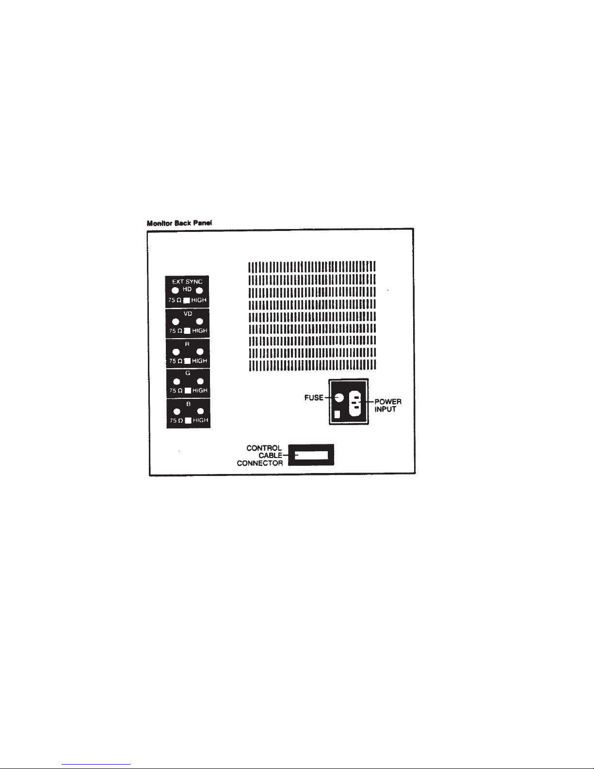
Monitor Back Panel
The Monitor Back Panel has several ports that connect the Monitor to the
Cabinet (see Figure 3-3).
•2 BNC sockets labeled
Ext Sync
are used for the video sync
connection from the Cabinet.
•2BNCsocketslabeled
V D
are not used.
•2 BNC sockets labeledR receive the red video signal from the
Cabinet.
•2 BNC sockets labeledG receive the green video signal from the
Cabinet.
•2 BNC sockets labeledB receive the blue video signal from the
Cabinet.
•15-ampfuse.
• 110-amp100/120voltpowerplugprovides powerfortheMonitor
from the Cabinet.
Page 14
10 IRIS WORKSTATION GUIDE
Version 1.0
IRIS Workstation Specications
Figure 3-3: Monitor Back Panel
Page 15
Version 1.0
IRIS WORKSTATION GUIDE 11 IRIS Workstation Specications
• 125-pinplugforconnectingacontrolcablefromtheCabinettothe
Monitor.
3.5 Cabinet
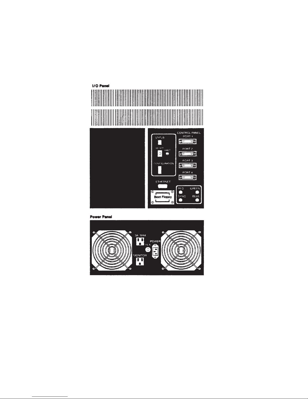
There are two control panels on the back of the IRIS 1400 Cabinet: an I/O Panel
and a Power Panel. A
Power
switch controls power for the IRIS Workstation
system.
Power Switch
The
Power
switch for the IRIS 1400 Workstation is located beside the tape drive
slot on the front upper-left corner of the Cabinet.
Cabinet I/O Panel
The Cabinet I/O Panel has ports for connecting the Cabinet to the Monitor and
a host computer (see Figure 3-4) and several control and indicator features.
•
Port 1
is the receptacle for the control cable that is connected
between the Monitor Back Panel and the Cabinet I/O Panel.
•
Port 2, Port 3
and
Port 4
are available for RS-232 or RS-423 serial
lines.
•115-pinDsocketlabeled
Ethernet
connects the IRIS Workstation to
an Ethernet drop cable.
•1 BNC socket labeled
Sync
is a port for the video sync cable
connecting the Cabinet and the Monitor.
•1BNCsocket labeled
Red
is a port for transmitting the red video
signal from the Cabinet to the Monitor through a coaxial cable.
•1BNCsocketlabeled
Green
is a port for transmitting the green video
signal from the Cabinet to the Monitor through a coaxial cable.
•1BNCsocketlabeled
Blue
is a port for transmitting the blue video
signal from the Cabinet to the Monitor through a coaxial cable.
•1
Reset
button is located on the Cabinet I/O Panel. Pressing this
button resets the processor which in turn resets the rest of the
system. After the
Reset
button has been pressed, the IRIS
Workstation must be rebooted. This switch and the
Halt
light
correspond to the
Reset
button and
Halt
light on the IRIS Control
Panel on the Monitor. Either button may be used.
Page 16
12 IRIS WORKSTATION GUIDE
Version 1.0
IRIS Workstation Specications
Figure 3-4: IRIS 1400 Cabinet Back Panel
Page 17

Version 1.0
IRIS WORKSTATION GUIDE 13 IRIS Workstation Specications
WARNING: Do not press the
Reset
button
while the IRIS Workstation is running UNIX.
If the IRIS Workstation is not running UNIX
and is under control of the PROM Monitor,
then the
Reset
buttons or the
Power
switches
may be used. See the discussion on Crash
Recovery in Section 6.14.
•1
Halt
LED indicates that the processor is stopped.
•1alphanumericdiagnosticLEDlabeled
Status
on the Cabinet I/O
Panel indicates system status and displays startup diagnostics.
•A series of nine DIP switches labeled
Configuration
is located on
the Cabinet I/O Panel. These switches control the IRIS Workstation’s
host serial line baud rate, startup diagnostics and boot environment
(see Appendix A).
Cabinet Power Panel
The Cabinet Power Panel has two power outlets and a power plug (see Figure
3-4).
•1male3-pininputpowerpluglabeled
Power
provides power for the
IRIS Workstation system.
•1switched2-amppoweroutletlabeled
Monitor
provides power for
the Monitor.
•1 unswitched 3-amp convenience outlet labeled
3A Max
provides
power for peripheral equipment.
•115-ampcircuitprotector(IRIS1400).
Power Switch
The
Power
switch located on the front of the Cabinet controls power for the
Cabinet and the Monitor. It does not control the power for any auxiliary
equipment connected to the Cabinet through the convenience outlet located on
the Cabinet Power Panel.
3.6 Documentation
The IRIS Workstation is delivered with a complete set of documentation.
•TheIRIS Workstation Guide (this booklet) explains how to install, test
and operate an IRIS Workstation.
•TheIRIS User’s Guide describes the IRIS Graphics Library and how to
write application programs for the IRIS Workstation and IRIS
Terminal.
Page 18

14 IRIS WORKSTATION GUIDE
Version 1.0
IRIS Workstation Specications
•TheCand FORTRANeditionsoftheIRIS Graphics Library are quick
reference cards with overviews of each command in the IRIS
Graphics Library.
•The UNIX Programmer’s Manual is a set of reference manuals and
tutorials for the UNIX System.
Page 19

4. Hardware Installation
This section describes how to install and connect the components that make up
an IRIS Workstation system (see Figure 4-1). Prior to installation, each
component should be unpacked and placed near its final location. Since the
IRIS Workstation components are delivered assembled, they only need to be
connected with the cables provided in the delivery cartons.
WARNING: Do not connect the IRIS Workstation to an
external power source until each cable has been
connected and checked.
4.1 Keyboard to Monitor Connection
The Keyboard cable is connected to the IRIS Control Panel located on the lower
left front of the Monitor (see Figure 3-2).
1. Connect the DIN plug on the Keyboard cable to the DIN socket
labeled
Keyboard
on the IRIS Control Panel.
4.2 Mouse to Monitor Connection
The Mouse cable is connected to the IRIS Control Panel located on the lower
left front of the Monitor (see Figure 3-2).
1. Connect the slide-locking D socket on the Mouse cable to the D plug
labeled
Mouse
on the IRIS Control Panel.
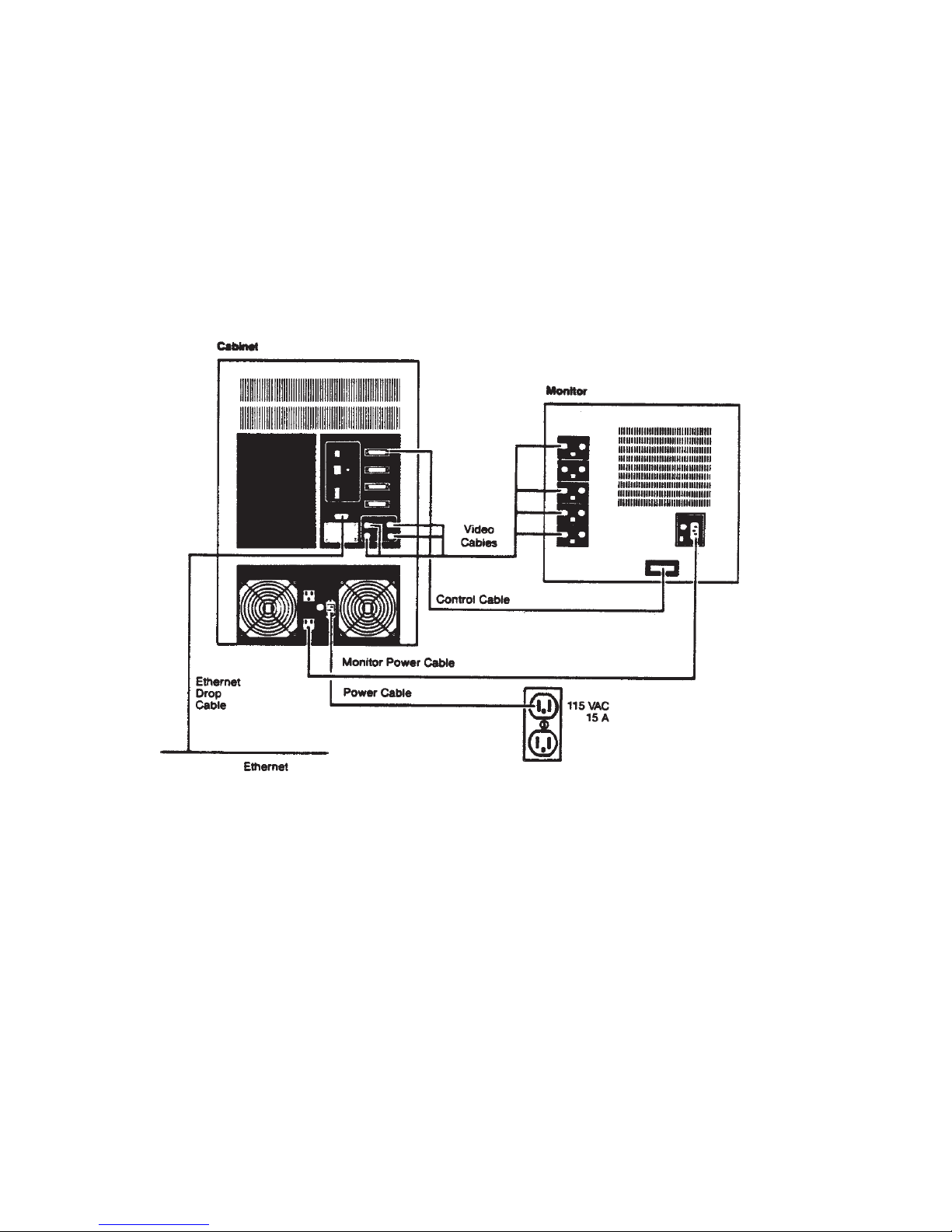
4.3 Monitor to Cabinet Video Connections
The color-coded bundle of coaxial video cables is connected between the
Cabinet I/O Panel and the Monitor Back Panel (see Figures 3-3, 3-4 and 4-1).
1. For single Monitor operation, set all of the input impedance switches
to the
75 Ω
position.
If several Monitors are connected in a series (daisy chain), set the
input impedance switches to the
High
position for all but the last
Monitor, which should be set to the
75 Ω
position.
2. Connect each cable end to an input socket on the Monitor Back
Panel. Since they are identical, either socket can be used.
Version 1.0
Page 20
16 IRIS WORKSTATION GUIDE
Version 1.0
Hardware Installation
Figure 4-1: IRIS 1400 Monitor to Cabinet Connections
Page 21

Version 1.0
IRIS WORKSTATION GUIDE 17 Hardware Installation
3. Push each cable into its connector and rotate its lock into place.
4. Connect the other end of each color-coded cable to the corresponding
output socket on the Cabinet I/O Panel.
5. Push the cable into the connector and rotate the lock into place.
4.4 Monitor to Cabinet Control Cable Connection
The Control Cable connects the Cabinet and the Monitor.
1. Connect the female end of the Control Cable to the 25-pin socket on
the Monitor Back Panel.
2. Connect the male end of the Control Cable to
Port 1
on the Cabinet
I/O Panel.
3. Fix the Control Cable into place by tightening the captive screws on
each side of both plugs.
4.5 Monitor to Cabinet AC Power Cable Connection
The Monitor power outlet is located on the Cabinet Power Panel (see Figure 34).
This switched AC outlet is controlled by the Cabinet
Power
switch.
1. Connect the female end of the AC power cable to the
Input
power
socket on the Monitor Back Panel.
2. Connect the male end of the Monitor power cable to the AC outlet
labeled
Monitor
on the Cabinet Power Panel.
4.6 IRIS Workstation to Serial Line Connection
The IRIS Workstation can be connected to a modem, a terminal or a printer
through a serial line attached to
Port 2, Port 3
or
Port 4
on the Cabinet I/O
Panel. The connection for each of these devices are slightly different. Each
physical device connection also has a corresponding UNIX software
configuration procedure. Sections 6.8, 6.9 and 6.10 describe these procedures.
Terminal Connection
1. Attach an RS-232 cable from the ASCII terminal to
Port 2, Port 3
or
Port 4
on the Cabinet I/O Panel. Appendix H has a description of
the RS-232 interface for the IRIS Workstation serial ports. These are
Data Terminal Equipment (DTE) type RS-232 ports. If the ASCII
terminal is also DTE type, then a null modem is required for the
connection. If the terminal is Data Communication/Circuit Terminating
Equipment (DCE) type, then a simple connection can be made
without a null modem. The manual for the ASCII terminal should
have a specification of its RS-232 interface.
Page 22

18 IRIS WORKSTATION GUIDE
Version 1.0
Hardware Installation
2. Turn on the power for the ASCII terminal.
3. See Section 6.8 for instructions on how to enable a serial port for
a terminal. This involves editing system configuration files and
resetting the software that enables the serial port on the IRIS
Workstation.
Modem Connection
1. Attach an RS-232 cable from the modem to
Port 2, Port 3
or
Port 4
on the Cabinet I/O Panel. Appendix H has a description of the RS232 interface for the IRIS Workstation serial ports.
2. Turn on the power for the modem.
3. See Section 6.9 for instructions on how to enable a serial port for
a modem. This involves editing system configuration files and
resetting the software that enables the serial port on the IRIS
Workstation.
Printer Connection
1. Attach an RS-232 cable from the printer to
Port 2, Port 3
or
Port 4
on the Cabinet I/O Panel. Appendix H has a description of the RS232 interface for the IRIS Workstation serial ports. The manual for
the printer should have a specification for its RS-232 interface.
2. Turn on the power for the printer.
3. See Section 6.10 for instructions on how to enable a serial port
for a printer. This involves editing system configuration files and
resetting the software that enables the serial port on the IRIS
Workstation.
4.7 IRIS Workstation to Ethernet Connection
The IRIS Workstation can communicate with other hosts and terminals through
an Ethernet local area network. The IRIS Workstation can be connected to an
Ethernet local area network while the network is operating.
1. Select an appropriate tap point on the Ethernet coaxial cable.
NOTE: Approved Ethernet coaxial cable is marked with rings at 8.2
foot intervals. Transceivers should be placed at these rings to
minimize the chance of transceiver reflections with phase angles that
add and cause transmission errors.
2. Tap into the Ethernet cable (instructions are included with each
transceiver).
Page 23

Version 1.0
IRIS WORKSTATION GUIDE 19 Hardware Installation
3. Connect the transceiver to the Ethernet cable.
4. Connect the male end of the drop cable to the Ethernet port on the
Cabinet I/O Panel.
5. Connect the female end of the drop cable to the transceiver.
4.8 Cabinet AC Power Connection
The Cabinet power socket is located on the Cabinet Power Panel.
CAUTION: Do not connect the IRIS Workstation to a
switched power outlet.
1. Connect the female end of the AC power cable to the power socket
on the Cabinet Power Panel (see Figure 3-4).
2. Connect the male end of the Cabinet power cable to an appropriate
outlet. See Table 2-1 for a specification of the power requirements
of the IRIS Workstation.
4.9 Cabinet to Dial and Switch Box Connection
The IRIS Workstation can be connected to an optional Dial and Switch Box for
sending information to an application program on the IRIS Workstation.
1. Connect the 37-pin flat cable from the port on the Dial Box to the
bottom left port on the Switch Box.
2. Connect the 9-pin cable from the top left port on the Switch Box to
Port 4
on the Cabinet I/O Panel. This RS-232 cable should be
enabled in the following way. Edit the file /etc/inittab. Each line
corresponds to a device file in /dev and contains four fields separated
by colons. Find the line for port d3 and put a x in the second field.
This prevents a getty process from being run on the port.
3. Plug the 3-wire AC power cable on the Switch Box into the
3A Max
convenience outlet on the Cabinet Power Panel.
Page 24

20 IRIS WORKSTATION GUIDE
Version 1.0
Hardware Installation
Page 25

5. Operation
The IRIS Workstation is a graphics-oriented micro-computer. To the user, it
looks like a standard System V UNIX computer. The sections that follow
outline the normal operation procedures used with the IRIS Workstation.
These include a simple boot procedure, login, compiling and running
demonstration programs, adjusting the Monitor, using the network software
and shutdown. Normally, the boot and shutdown procedures are handled by
the system administrator. They are covered here in outline form only.
The IRIS Workstation can be configured by the customer in many ways. These
include adding new accounts, new terminals and printers and connecting it to
a local area network. See Section 6 for an explanation of system administration
for the IRIS Workstation.
NOTE: The sections that follow assume that the reader
has some experience with the UNIX system as a user.
5.1 Boot
The IRIS Workstation can be booted in many different ways but the simplest
and most common is to boot off of a disk.
NOTE: UNIX single-user mode should be used only for
system maintenance. Normal operation should occur only
in multi-user mode.
1. Check the configuration switches on the I/O Panel on the rear of the
Cabinet (see Figure 3-4). Switches 4 through 7 should be in the
Closed
position. Switch 8 should be in the
Open
position.
2. Turn on the power for the IRIS Workstation.
3. These steps will boot the IRIS Workstation in single-user mode. A
UNIX prompt will appear.
#
4. The file system will be checked automatically during the boot
process to insure their integrity. fsck is mostly automatic. If fsck
finds anything out of the ordinary, it will prompt the user for a
decision. See Section 6 and Appendix B or consult with the system
administrator.
Version 1.0
Page 26

22 IRIS WORKSTATION GUIDE
Version 1.0
Operation
5. Start multi-user mode with the multi command.
# multi
...
6. Set the date.
CAUTION: It is important to accurately set
the date since many system programs depend
on the time. Also, several user programs like
make determine their actions based on the
relative dates of files. Accurate system time is
even more important for program development
distributed across a network.
The input format of the date command is “mmddhhmmyy” [month-
day-hour-minute-year(optional)]. For example,
Is the date Wed Mar 21 14:16:42 PST 1984? (y or n) n
Enter the correct date: 0322091484
Is the date Thu Mar 22 09:14:01 PST 1984? (y or n) y
...
If the time zone appears to be incorrect, see Section 6.5 and TZ(4).
A UNIX login prompt should then appear.
7. Log into a UNIX account. The IRIS Workstation is shipped with
three user accounts: rootcsh, root and guest. The rootcsh account is a
privileged account with a C Shell environment. The root account is
a privileged account with a Bourne Shell environment. The guest
account is a sample user account with a C Shell environment. New
accounts can be added by the system administrator (see Section 6.7).
login: guest
8. Accounts frequently have passwords for protection. Enter the
password.
password:
...
The password’s characters will not be echoed onto the terminal
screen. Note that the guest does not have a password. See passwd(1)
and Section 6.7 for information on how to add or change a password
for an account.
5.2 Demonstration Programs
After the IRIS Workstation has been booted, it can be tested by running the
demonstration programs included in the directory /usr/demos. These include
some simple programs like particles and some more sophisticated programs like
ight. To run any of these programs, simply type its name. For example,
Page 27

Version 1.0
IRIS WORKSTATION GUIDE 23 Operation
$ cd /usr/demos
$ particles 15
...
runs the particles program. In this demonstration program, 15 particles are set in
random motion in a cube. When one of the particles touches a boundary of the
cube, it emits a square bubble that inflates to a certain size and then pops.
Generally, these demonstration programs can be exited by typing
CONTROL
-c. To
clear the screen of graphics “leftovers”, type the command gclear.
The IRIS User’s Guide documents the IRIS Graphics Library, the software that a
programmer uses to write applications for the IRIS Workstation. In the second
section of that manual, the IRIS Graphics Library, there are a few sample
programs that illustrate how the graphics software is used. On page 2-57 of
that manual, there is a program listing for a program called track. This program
can be compiled and run on the IRIS Workstation. For example,
$ cc track.c -o track -Zg
See cc(1) for information on the C and FORTRAN compilers for the IRIS
Workstation.
After track has been compiled, it can be run.
$ track
A blue box will appear on the screen which can be moved around with the
Mouse. To exit track, press all three Mouse buttons or
CONTROL
-c.
5.3 Monitor Adjustment
The Monitor Control Panel on the right side of the Monitor has several knobs
for adjusting the brightness and contrast of the Monitor.
NOTE: Color rendering and stability may drift for the
first 45 minutes after startup.
1. After the Monitor has warmed up, adjust the
Brightness
control
knob until the gray raster is barely brighter than the black areas on
the edge of the screen. Lighter brightness settings will impair image
sharpness and color fidelity.
2. For optimum clarity, turn the
Contrast
control knob to the maximum
(clockwise) setting and then turn it back slightly.
3. If the color purity or convergence appear to be out of adjustment,
hold down the
Degauss
button on the Monitor Control Panel for
about 10 seconds and then release it. The image should then
improve noticeably.
Page 28

24 IRIS WORKSTATION GUIDE
Version 1.0
Operation
5.4 Network Software
The IRIS Workstation has three programs for using an Ethernet local area
network: xcp, xx and xlogin. These simple commands allow the user to copy
files from one host to another, run commands on a remote host and log into a
remote host.
Here is a brief explanation of certain terms associated with networks.
• A network is a collection of computers and terminals connected by
some means.
• Ahost is a computer on a network.
• Alocal host is the host that a person is using.
• A remote host is the opposite of a local host. That is, it is a machine
on a network that a person is not using. The difference between a
local and a remote host is the frame of reference one uses. The local
host is where the user is and remote host is “where” the user isn’t.
xcp copies file from one host (either local or remote) to another (also either local
or remote). Here are some examples:
$ xcp sqiral.c olympus:/oh4/doc/install/sqiral.c
$ xcp sting:/usr/include/stdio.h te
$ xcp puppy:temp_vi sting:temp_vi
NOTE: In each example, the user must have an account
with the same user name on each host.
The first example copies a file in the current directory of the remote machine
to the file sqiral.c in the directory /oh4/doc/install on the host named olympus. The
second example copies a file from the host olympus to the local machine. The
third example copies a file from one remote machine named puppy to another
named sting.
The second command xx is useful for running short commands on a remote
host. Again, this command assumes that the user has an account on the
remote machine with the same user name as on the local machine. For
example, it may be useful to find what the load average is on another
machine:
$ xx olympus uptime
1:51pm up 21:14. 30 users. load average: 12.14 11.34 10.25
The third command xlogin allows the user to login across a network on a remote
host. All that is needed is a host name. For example,
$ xlogin olympus
login:
...
For more information about the network software for the IRIS Workstation, see
the manual entries in Appendix F.
Page 29

Version 1.0
IRIS WORKSTATION GUIDE 25 Operation
5.5 Shutdown
The IRIS Workstation should not be left on indefinitely. However, since the
Monitor has a long warmup period, the IRIS Workstation should be left on
continuously during work hours.
WARNING: Do not press either
Reset
button or the
Power
switch while the IRIS Workstation is running
UNIX without first using the /etc/reboot -q command listed
below. If the IRIS Workstation is under the control of the
PROM Monitor, then the
Reset
buttons and the
Power
switch may be safely used.
1. To shut down UNIX, type the /etc/reboot -q command.
$ /etc/reboot -q
NOTE: /etc/reboot -q is a privileged command,
requiring super-user permission.
2. Set the
Power
switch on the Cabinet to the
Off
position.
Page 30

26 IRIS WORKSTATION GUIDE
Version 1.0
Operation
Page 31

6. System Administration
The system administrator is responsible for configuring the IRIS Workstation to
meet local requirements. The sections that follow explain how to boot the IRIS
Workstation, check the file system, configure UNIX, add new accounts, add
ASCII terminals and modems, make backups, shutdown the IRIS Workstation
and recover from a crash.
This document uses the standard UNIX convention for refering to entries in the
UNIX reference manual. The entry name is followed with a section number in
parentheses. For example, cc(1) refers to the cc manual entry in Section 1 in the
UNIX Programmer’s Manual.
6.1 Startup
Startup options can be selected by setting certain configuration switches on the
Cabinet Back Panel. These switches control the environment the IRIS
Workstation will be booted from and the display of checkout information about
the boot state (see Appendix A).
The IRIS Workstation can be booted from either a disk drive or a tape drive.
These devices can be used automatically or explicitly through the PROM
Monitor. Automatic boot procedures involve setting configuration switches
and turning on the system power. The PROM Monitor is a simple command
interpreter through which all boot environments can be accessed. The user
gives a PROM Monitor command that specifies the boot device.
NOTE: If a non-existent device is specified as a boot
environment, then the IRIS Workstation will ignore the request
and wait to be reset.
Automatic Disk Drive Boot
If the
Boot Environment
configuration switches are set to “00001”, the IRIS
Workstation will search for and read a boot file named defaultboot in the root file
system after the system power is turned on.
1. Set the
Boot Environment
configuration switches (switches 4 through
8) to “00001” where “0” means
Closed
and “1” means
Open
. See
Appendix A.
Version 1.0
Page 32

28 IRIS WORKSTATION GUIDE
Version 1.0
System Administration
2. Set the
Power
switch on the Cabinet to the On position.
A variation of this boot procedure can be used explicitly through the PROM
Monitor. See the entries for the PROM Monitor d command in Table 6-1.
Automatic Tape Drive Boot
If the
Boot Environment
configuration switches are set to “10000”, the IRIS
Workstation will search for and read a boot file named defaultboot from the tape
drive. The IRIS Workstation will be booted automatically after the system
power is turned on.
NOTE: If the IRIS Workstation is to be booted from a
tape drive, the tape must be in cpio(1) format.
1. Set the
Boot Environment
configuration switches (switches 4 through
8) to “10000” where “0” means
Closed
and “1” means
Open
. See
Appendix A.
2. Set the
Power
switch on the Cabinet to the On position.
A variation of this boot procedure can be used explicitly through the PROM
Monitor. See the entries for the PROM Monitor tb command in Table 6-1.
PROM Monitor
The PROM Monitor is a simple command interpreter through which each IRIS
Workstation boot environment can be accessed. If the
Boot Environment
configuration switches are set to “01000”, the IRIS Workstation will be under
the control of the PROM Monitor when the system power is turned on.
1. Set the
Boot Environment
configuration switches (switches 4 through
8) to “01000” where “0” means
Closed
and “1” means
Open
. See
Appendix A.
2. Set the
Power
switch on the Cabinet to the On position.
3. The PROM Monitor prompt should appear on the IRIS Monitor
screen. If it doesn’t, press the
Halt
button on either the IRIS
Control Panel on the front of the Monitor or the I/O Panel on the
back of the Cabinet.
iris>
4. Boot the UNIX kernel.
iris> d
...
This command causes the IRIS Workstation to search for and read a
boot file named defaultboot in the root file system.
Page 33

Version 1.0
IRIS WORKSTATION GUIDE 29 System Administration
Since the IRIS Workstation can be booted from different environments (hard
disks, tape drives, etc.) it may be useful to find the names of the files on a tape
or disk before booting the IRIS Workstation. This information can be found
with the PROM Monitor. For example,
iris> d *
bin etc stand unix1
defaultboot lib tmp usr
dev lost+found unix version
iris>
searches the root file system and lists its contents. After locating a file, it can be
booted explicitly with the d command. For example,
iris> d unix
...
See Table 6-1 for a list of the commands available through the PROM Monitor.
6.2 Boot Checkout Information
If the
Checkout
configuration switch (switch 3) is set to the
Open
position, the
IRIS Workstation will display additional information during system startup.
• Scanprocessormemory.An“X”isdisplayedforeachhalfmegabyte
of memory and a “.” is displayed for each non-existent half megabyte
of memory.
•Clearprocessormemory.
•Mapprocessormemory.
•Displayconfigurationswitchvalues.
This information is intended for diagnostic purposes only. Normally the
Checkout
configuration switch should be set to the
Closed
position.
6.3 UNIX Single-User Mode
After the IRIS Workstation has been booted, it will display some system
information. See Figure 6-1 for an example. This includes information about the
software release, memory size, hardware configuration and the file system.
NOTE: UNIX single-user mode should be used only for
system maintenance. Normal operation should occur
only in multi-user mode.
Initially the IRIS Workstation is booted in UNIX single-user mode. The
following procedure starts multi-user mode and sets the date. The important
file for starting multi-user mode is /etc/rc. It contains commands for starting
daemons and mounting file systems. See brc(1).
Page 34

30 IRIS WORKSTATION GUIDE
Version 1.0
System Administration
Command Description
h
Display a list of PROM Monitor commands.
t
Enter serial interface to host.
n [le] Boot le over a network.
d
Boot defaultboot from a disk. Similar to the Disk Drive
Boot procedure.
d [le] Boot le from a disk.
d [pathname]/* List the contents of directory pathname.
tb
Boot defaultboot from a tape drive. The file must be in cpio
format. Similar to the Tape Drive Boot procedure.
tb [le] Boot le from a tape drive. The file must be in cpio
format.
tb *
List the contents of a tape in cpio format.
r
Restart the PROM Monitor.
Table 6-1: PROM Monitor Commands
1. Start multi-user mode.
# multi
2. Set the date. The input format of the date command is
“mmddhhmmyy” [month-day-hour-minute-year(optional)]. For
example,
Is the date Wed Mar 21 14:16:42 PST 1984? (y or n) n
Enter the correct date: 0322091484
Is the date Thu Mar 22 09:14:01 PST 1984? (y or n) y
...
A UNIX login prompt will then appear.
3. Log into a UNIX account. The IRIS Workstation is shipped with
three user accounts: rootcsh, root and guest. The rootcsh account is a
privileged account with a C Shell environment. The root account is
a privileged account with a Bourne Shell environment. The guest
account is a sample user account with a C Shell environment. New
accounts may be added by the system administrator (see Section
6.7).
login:
...
Page 35

Version 1.0
IRIS WORKSTATION GUIDE 31 System Administration
Kernel Number:
SYSTEM 5 UNIX #135: [Fri May 4 11:15:09 PST 1984]
Release ID:
Release: Beta-1.5
(C) Copyright 1983 - UniSoft Corporation
(C) Copyright 1983 - Silicon Graphics Inc.
Kernel Size:
kmem = 290816
Approximate Available Memory:
avail = 1282048
Hardware Conguration:
dsd at mbio 0x1f00 ipl 1
qic0 (QIC Quarter Inch Cartridge Tape) slave 0
md0 (Vertex V170 Name: XORN drive 0) slave 0
md1 (Vertex V170 Name: Beta Version 1.2 (4/10/84) slave 1
mf0 not installed
nx0 at mbio 0x0010 ipl 2
ge0 at mbio 0x1400 ipl 4
fbc0 at mbio 0x1c00 ipl 3
Root File System Device Name:
root on md0a
Swap Space Device Name and Size:
swap on md0b (8865K of swap space)
Single-User Mode Banner:
INIT: SINGLE USER MODE
Silicon Graphics Inc.
IRIS 1400 Workstation
Single-User Prompt:
#
Figure 6-1: IRIS Workstation Boot Information
Page 36

32 IRIS WORKSTATION GUIDE
Version 1.0
System Administration
File Systems and fsck(1M)
The disk drive on an IRIS Workstation has several partitions that are
represented by device files in the /dev directory. Three of them are of interest
to the user: the root file system (/dev/md0a), the swap space (/dev/swap) and the
/usr file system (/dev/md0c). The root file system is always mounted when
UNIX is running. The /usr file system is unmounted in single-user mode.
These file systems should be checked with fsck before multi-user mode is
started and the other file systems are mounted. fsck is an interactive file system
check and repair program. Generally, fsck prompts for a yes or a no reply
before altering a corrupted file system. The most common problem that fsck
discovers is a bad i-node count resulting from an improper shutdown. For
more information on fsck, see Appendix B.
The files /.login and /.prole contain a command line for running fsck during
system startup. The file /etc/rc contains a command line for mounting the /usr
file system.
6.4 Conguring UNIX on an IRIS Workstation
One of the strengths of the UNIX operating system is its flexibility. A given
UNIX system can be configured in a variety of ways. Choices include
hardware configurations, like the amount of memory a system has, and
software configurations, like where a program is located and who has
permission to use it.
On the user level, there are even more choices. For example, each user can
choose how the system finds commands, whether other people can use his or
her files and whether or not to override certain system defaults. Each user can
establish an environment that he or she feels comfortable with.
The IRIS Workstation is shipped with a minimum set of non-standard system
defaults. Each system administrator can then configure the IRIS Workstation to
suit the needs of the local user community and each user can then fine tune his
or her personal environment.
NOTE: The discussion that follows assumes that the
reader understands UNIX system administration. For
more information, see the UNIX Programmer’s Manual.
The sections that follow contain instructions for common system administration
tasks for the IRIS Workstation.
6.5 Conguration Files
There are several files in the directories /etc and /usr that may or should be
edited by the IRIS Workstation system administrator.
Page 37

Version 1.0
IRIS WORKSTATION GUIDE 33 System Administration
/etc/TZ This file contains an entry for the time zone. Several
different utilities determine their time zone from this
file. There are three fields in /etc/TZ:
1) standard heading for time zone,
2) offset from Greenwich Mean Time,
3) optional daylight savings time zone.
For example, the IRIS Workstation is shipped with the
time zone set for Pacific Standard Time.
PST8PDT
For more information, see TZ(4).
/etc/checklist Thislecontainsalistoflesystemsprocessedbyfsck
/etc/cshrc This file is read at login by accounts that specify the C
Shell as the login shell. See csh(1).
/etc/gettydefs This file contains entries for line speeds and terminal
settings used by getty(1M) when it initializes a device.
In addition, each line has a field that is displayed
when its corresponding port is used to login. See
Sections 6.8 and gettydefs(4).
/etc/group This file contains information about groups. See
Section 6.7 and group(4).
/etc/inittab This file contains an entry for each device that init(1)
will initialize. See Sections 6.8, 6.9, 6.10, 6.11,
inittab(4) and telinit(1M).
/etc/motd This file contains the message of the day. It is
displayed each time a user logs into an IRIS
Workstation.
/etc/passwd This file contains information about people who have
accounts on an IRIS Workstation. See Section 6.7 and
passwd(4).
/etc/profile This file is read at login by accounts that specify the
Bourne Shell as the login shell. See sh(1).
/etc/rc This command file is read by init(1) at the
start of multi-user mode. Typically, it is used to start
daemons and run other commands at system startup.
See brc(1).
/etc/sys_id This file contains the name of the system. See Section
6.6, hostname(1) and sys_id(4).
/etc/termcap This file contains entries for different terminal types.
See Section 6.8 and termcap(4).
Page 38

34 IRIS WORKSTATION GUIDE
Version 1.0
System Administration
/etc/ttytype This file maps terminal types to devices attached to an
IRIS Workstation. See Sections 6.8, 6.11, tset(1) and
ttytype(4).
/usr/lib/crontab This file contains entries for commands to be run at
xedintervalsbythecron(1M) daemon. See cron(1M).
/usr/lib/uucp/L-devices This file contains line speed entries for each port used
by uucp(1). See Section 6.9.
/usr/lib/uucp/L.sys This file contains information about sites that uucp(1)
can communicate with. See Section 6.9.
6.6 Naming an IRIS Workstation
Each IRIS Workstation is shipped with the name IRIS. To change this, edit the
file /etc/sys_id, insert a new name and reboot the system. Be sure that there are
no blanks in the name and that it is fewer than 14 characters long.
6.7 Adding a New Account
New accounts can be created on the IRIS Workstation by adding a line to the
file /etc/passwd. Additionally, the system administrator can set up the new user’s
environment with startup files, home directories, etc. These are largely matters
of personal taste and will not be covered here except in outline form.
1. Edit the file /etc/passwd. This file contains a line for each account on a
UNIX system. Each line has seven fields separated by colons (:). See
passwd(4).
1) Account Name
2) Encrypted User Password
3) User Number
4) Group Number
5) Name
6) Home Directory (default /)
7) Login Shell (default /bin/sh)
Figure 6-2 contains an example /etc/passwd file.
Add a line for the new account. Be sure that it contains a group
number and a unique account name and user number. The home
directory should be specified in the sixth field. The login shell
should be specified in the seventh field. For example, to add an
account for a user named peter the following line might be inserted:
peter::10:20:Peter Broadwell:/usr/staff/peter:/bin/csh
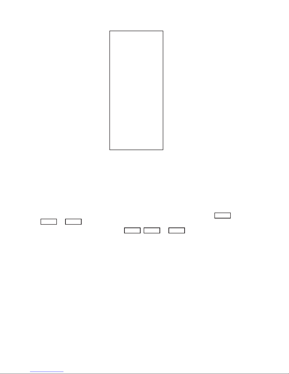
2. Edit the file /etc/group to include the new user in any additional
groups. Entries to this file are optional. See group(4). Figure 6-3
contains an example /etc/group file. Each line corresponds to a
Page 39

Version 1.0
IRIS WORKSTATION GUIDE 35 System Administration
root::0:0:Superuser:/:/bin/csh
rootcsh::0:0:Superuser:/:/bin/csh
rootsh::0:0:Superuser:/:/bin/sh
daemon:*:1:1::/:
bin:*:2:2:Binary Files:/:
uucp:*:3:5:UUCP Login Account:/usr/spool/uucpPublic:/usr/lib/uucp/uucico
adm:*:5:3:Administration:/usr/adm:
uucpadm:*:8:8:UUCP Administration:/usr/lib/uucp:
lp:*:9:9:Line Printer:/:
guest::998:998::/usr/people/guest:/bin/csh
Figure 6-2: Sample /etc/passwd File
group. There are four fields to a line. The asterisk in the second
field indicates that there is no group password.
1) Group Name
2) Encrypted Group Password
3) Group Number
4) Group Members
If the new user wishes to be included in the group adm, then the
system administrator can append the user ’s name to the line for the
group adm. User names in this field are separated by commas.
adm:*:3:henry,peter
3. Make a home directory for the new user. The ownership, file and group
protections should also be set for the new directory. For example,
$ mkdir /usr/staff/peter
$ chgrp user /usr/staff/peter
$ chmod 755 /usr/staff/peter
$ chown peter /usr/staff/peter
mkdir(1) makes the home directory for the new user. chgrp(1)
changes the group of the new directory. The chmod(1) command is
used to set the protection parameters on a file or directory. These
parameters can also be set by the owner of the file or directory.
chown(1) is a privileged command that changes the ownership of the
directory.
4. The new user can create a password with the passwd command
when he or she first logs in.
$ passwd
New password:
Re-enter new password:
$
5. The final step is to add startup files like .cshrc, .login and .prole in
the new user’s home directory. This is largely a matter of personal
Page 40
36 IRIS WORKSTATION GUIDE
Version 1.0
System Administration
sys:*:0:
system:*:0:
daemon:*:1:
bin:*:2:
adm:*:3:
sgi_use:*:4:
uucp:*:5:uucp
sgi_use:*:6:
sgi_use:*:1:
uucpadm:*:8:uucp
lp:*:9:
sgi_use:*:10:
sgi_use:*:11:
sgi_use:*:12:
sgi_use:*:13:
sgi_use:*:14:
sgi_use:*:15:
sgi_use:*:16:
sgi_use:*:11:
sgi_use:*:18:
sgi_use:*:19:
guest:*:998:
games:*:999:
user:*:20:
Figure 6-3: Sample /etc/group File
taste. For examples, see the files in /usr/guest. Copy these files into the
new home directory and edit them to suit the needs of the new user.
See csh(1) and sh(1).
6.8 Connecting an ASCII Terminal to the IRIS Workstation
ASCII terminals can be connected to the IRIS Workstation through
Port 2
,
Port 3
or
Port 4
on the Cabinet I/O Panel (see Figure 3-4).
1. Connect a serial line to
Port 2, Port 3
or
Port 4
. See Section 4.6 for
instructions on how to physically connect the IRIS Workstation to a
terminal with an RS-232 serial line.
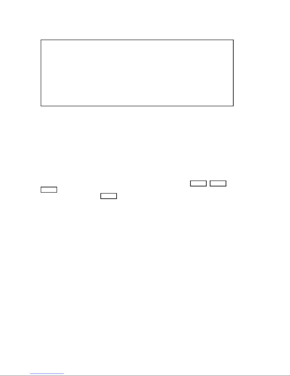
2. Edit the file /etc/inittab. Each line corresponds to a device file in /dev
and contains four fields separated by colons. See Table 6-2 for a list
of the correspondences between device files and physical ports on
the Cabinet I/O Panel. Find the line in /etc/inittab for the selected
port and delete the x in the second field. Figure 6-4 contains an
example /etc/inittab file. See inittab(4) for more information.
3. init must be informed of the change to the /etc/inittab file.
$ /etc/telinit -q
This causes init to read /etc/inittab and start getty processes on each
Page 41

Version 1.0
IRIS WORKSTATION GUIDE 37 System Administration
File Description
console
oppy
kmem
md0a
md0c
md1a
md1c
mem
mt1
nrtape
null
rmd0a
rmd0c
rmd1a
rmd1c
rmt1
rqic
swap
syscon
systty
tty
ttyd1
ttyd2
ttyd3
ttyn*
EXOS/*
Console terminal.
Optional floppy disk drive.
Kernel memory (used by ps(1)). See mem(7).
Disk zero root (/) file system.
Disk zero usr (/usr) file system.
Optional disk one first file system.
Optional disk one second file system.
Memory (used by ps(1)). See mem(7).
Cartridge magnetic tape.
Cartridge magnetic tape (no rewind on open or close).
Null device (zero length on input, data sink on output).
See null(7).
Disk zero root (/) file system (raw device).
Disk zero usr (/usr) file system (raw device).
Optional disk one first file system (raw device).
Optional disk one second file system (raw device).
Cartridge magnetic tape (treated as a blocked device).
Cartridge magnetic tape (treated as a blocked device).
Swap device (used by ps(l)).
System console (linked to /dev/console).
System console (linked to /dev/console).
A synonym for the tty device associated with a process.
See termio(7) and tty(7).
Port 2 on Cabinet I/O Panel.
Port 3 on Cabinet I/O Panel
Port 4 on Cabinet I/O Panel.
Network ports.
IP/TCP for future releases.
Table 6-2: Special Device Files in /dev
port selected in /etc/inittab.
4. If the default speed set in /etc/inittab is incorrect, the user can select
another speed by pressing the
BREAK
key. The line speed choices for
each port are set in the file /etc/gettydefs. See gettydefs(4). Figure 6-5
contains an example /etc/gettydefs file.
5. Edit the file /etc/ttytype. This file maps a terminal type to each
device. Figure 6-6 contains an example /etc/ttytype file. Each port is
mapped to a device as in Table 6-2.
Each user’s Shell startup file should have tset commands that read
/etc/ttytype and set the terminal type. See Table 6-3 for example
commands. These should be included in each C Shell (csh (1)) user’s
.login file and each Bourne Shell (sh (1)) user’s .prole file. See
Page 42
38 IRIS WORKSTATION GUIDE
Version 1.0
System Administration
is:s:initdefault:
fp::sysinit:/etc/fload >/dev/console 2>&1
bl::bootwait:/etc/bcheckrc </dev/console >/dev/console 2>&1 #bootlog
bc::bootwait:/etc/brc 1>/dev/console 2>&1 #bootrun command
sl::wait:(rm -f /dev/syscon;ln /dev/systty /dev/syscon;) 1>/dev/console 2>&1
rc::wait:/etc/rc 1>/dev/console 2>&1 #run com
pf::powerfail:/etc/powerfail 1>/dev/console 2>&1 #power fail routines
co::respawn:/etc/getty console co_9600
d1:x:respawn:/etc/getty ttyd1 dx_9600
d2:x:respawn:/etc/getty ttyd2 dx_9600
d3:x:respawn:/etc/getty ttyd3 dx_9600
n1:x:respawn:/etc/getty ttyn1 dx_9600
n2:x:respawn:/etc/getty ttyn2 dx_9600
Figure 6-4: Sample /etc/inittab File
tset(1) and ttytype(4).
6. If necessary, edit the file /etc/termcap to contain entries for terminals
not described there. See termcap(4).
7. Login on the ASCII Terminal.
6.9 Connecting a Modem to the IRIS Workstation
A modem can be connected to the IRIS Workstation through
Port 2, Port 3
or
Port 4
on the Cabinet I/O Panel. This modem can then be used by the UNIX
utilities cu and uucp.
Port 3
should be used first since the serial line
configuration files are prepared for it. To attach a modem to any of the other
ports requires modification of the serial line configuration files.
1. See Section 4.6 for instructions on how to physically connect the
IRIS Workstation to a modem with an RS-232 serial line.
2. Edit the file /etc/inittab. Each line corresponds to a device file in /dev
and contains four fields separated by colons. See Table 6-2 for a list
of the correspondences between device files and physical ports.
Find the line for the selected port and put an x in the second field.
This prevents a getty process from being started on the port. See
inittab(4).
3. init must be informed of the change to the /etc/inittab file.
$ /etc/telinit -q
This causes init to read /etc/inittab and enable ports for modem use.
4. Edit the file /usr/lib/uucp/L-devices. This file contains line speed entries
for each port. See Section 1.3 for a description of the fields in each
line of /usr/lib/uucp/L-devices.
5. Edit the file /usr/lib/uucp/L.sys. This file contains information about
sites that uucp can communicate with. See Section 1.3 for a
Page 43

Version 1.0
IRIS WORKSTATION GUIDE 39 System Administration
co_9600# B9600 # B9600 SANE TAB3 #\r\n\nIRIS login: #co_4800
co_4800# B4800 # B4800 SANE TAB3 #\r\n\nIRIS login: #co_2400
co_2400# B2400 # B2400 SANE TAB3 #\r\n\nIRIS login: #co_1200
co_1200# B1200 # B1200 SANE TAB3 #\r\n\nIRIS login: #co_300
co_300# B300 # B300 SANE TAB3 #\r\n\nIRIS login: #co_9600
dx_9600# B9600 # B9600 SANE TAB3 #\r\n\nIRIS login: #dx_9600
dx_4800# B4800 # B4800 SANE TAB3 #\r\n\nIRIS login: #dx_4800
dx_1200# B1200 # B1200 SANE TAB3 #\r\n\nIRIS login: #dx_1200
du_1200# B1200 # B1200 SANE TAB3 #\r\n\nIRIS login: #du_300
du_300# B300 # B300 SANE TAB3 #\r\n\nIRIS login: #du_1200
Figure 6-5: Sample /etc/gettydefs File
description of the fields in each line of /usr/lib/uucp/L.sys.
6. Test the serial line with cu(1C), the UNIX terminal emulator.
$ cu -s1200 -lttyd3 9603515
7. Test the serial line with uucp(1C), the UNIX serial line file transfer
program. See Appendix I for an explanation of UUCP system
administration.
The procedure above is intended for a dial-out modem. To connect a modem
to the IRIS Workstation for dial-in use, a getty must be started on the
appropriate port. To do this, edit /etc/inittab and delete the x in the second
field of the line corresponding to the selected port. Then run telinit -q to have
init reread /etc/inittab.
6.10 Connecting a Printer to the IRIS Workstation
A printer can be connected to the IRIS Workstation through
Port 2, Port 3
or
Port 4
on the Cabinet I/O Panel.
1. See Section 4.6 for instructions on how to physically connect the
IRIS Workstation to a printer with an RS-232 serial line.
2. Edit the file /etc/inittab. Each line corresponds to a device file in /dev
and contains four fields separated by colons. See Table 6-2 for a list
of the correspondences between device files and physical ports.
Find the line for the selected port and put an x in the second field.
This prevents a getty process from being run on the port. See
inittab(4).
Page 44

40 IRIS WORKSTATION GUIDE
Version 1.0
System Administration
iris systty
iris console
iris syscon
v50am ttyd2
du ttyd3
du ttyd4
v50am ttyn1
v50am ttyn2
Figure 6-6: Sample /etc/ttytype File
3. Link the device file for the printer port to /dev/lp. For example, to
link the device file for
Port 3
,
# ln /dev/ttyd3 /dev/lp
4. Make the printer port writable to every user.
# chmod 666 /dev/lp
5. If the printer has XON/XOFF capabilities, initialize the port with
stty. See stty(1). For example,
# (stty -ixon ; sleep 100000) < /dev/lp
This line should then be added to the system startup file /etc/rc.
6. init must be informed of the change to the /etc/inittab file.
$ /etc/telinit -q
This causes init to read /etc/inittab and enable a port for the line
printer.
7. Test the line printer.
# cat /etc/passwd > /dev/lp
# lpr /etc/passwd
# pr -f -l66 /etc/rc | lpr
6.11 Enabling a Network Connection to the IRIS Workstation
The IRIS Workstation can be connected to an Ethernet local area network.
1. See Section 4.7 for instructions on how to physically connect the
IRIS Workstation to an Ethernet local area network network.
2. Edit the file /etc/inittab. Each line corresponds to a device file in /dev
and contains four fields separated by colons. See Table 6-2 for a list
of the correspondences between device files and physical ports.
Find the line for the selected port and delete the x in the second
field. See inittab(4) for more information.
3. init must be informed of the change to the /etc/inittab file.
Page 45

Version 1.0
IRIS WORKSTATION GUIDE 41 System Administration
C Shell (.login) Bourne Shell (.prole)
set noglob
set temp=(‘tset -Q -S’)
setenv TERM $temp[1]
setenv TERMCAP “$temp[2]”
unset temp
unset noglob
eval ‘tset -Q -s’
Table 6-3: tset Commands for Startup Files
$ /etc/telinit -q
This causes init to read /etc/inittab and enable ports for network
login.
4. Edit the file /etc/ttytype. This file maps each device to a terminal type.
See Figure 6-6 for an example /etc/ttytype file. Each network port is
mapped to a device as in Table 6-2.
Each user’s Shell startup file should have tset commands that read
/etc/ttytype and set the terminal type. See Table 6-3 for example
commands. These should be included in each C Shell (csh (1)) user’s
.login file and each Bourne Shell (sh (1)) user’s .prole file. See
tset(1) and ttytype(4).
5. Login through the network to another host.
6.12 Tape Drive
The IRIS Workstation has an optional tape drive for backing up file systems on
the disks and for reading new software distributions. See Table 6-4 for a list of
tape drive specifications. In addition, the IRIS Workstation can be booted from
the tape drive in case the root file system is damaged beyond repair (see
Section 6.1).
The tape drive can be used with either tar(1) or cpio(1), the standard UNIX
archiving tools. cpio is slightly favored. The tape boot procedure mentioned in
Section 6.1 requires a tape in cpio format. Keep a copy of the root file system
on tape to ensure that there is a reliable copy in the event of a bad crash. See
Table 6-5 for some UNIX commands for using the tape drive. See tar(1) and
cpio(1).
6.13 Shutdown
The IRIS Workstation should not be left on indefinitely. However, since the
Monitor has a long warmup period, the IRIS Workstation should be left on
continuously during work hours.
Page 46
42 IRIS WORKSTATION GUIDE
Version 1.0
System Administration
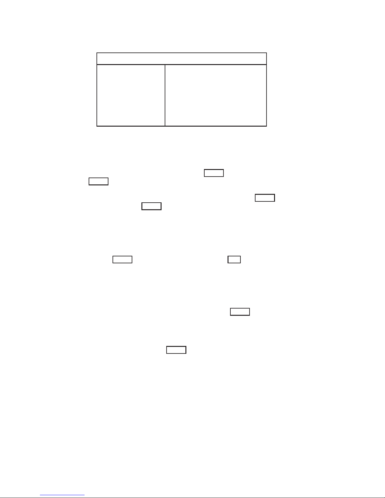
Tape Drive Specifications
Device Name:
Density:
Speed:
Tape Lengths:
Suppliers:
/dev/rmt1
10,000 flux changes per inch
l00K per foot
90 inches per second
300 and 450 feet
3M/Scotch
Data Electronics, Inc.
Table 6-4: Tape Drive Specifications
WARNING: Do not press either
Reset
button or the
Power
switch while UNIX is running without first using
the /etc/reboot -q command. If the IRIS Workstation is
under the control of the PROM Monitor, then the
Reset
buttons and the
Power
switch may be safely used.
1. To shut down UNIX, type /etc/reboot -q.
$ /etc/reboot -q
NOTE: /etc/reboot -q is a privileged command
requiring super-user permission.
2. Set the
Power
switch on the Cabinet to the
Off
position.
6.14 Crash Recovery
This section is necessarily incomplete. See Appendix C for a list of error
messages and probable causes. If the IRIS Workstation stops running for some
reason, first try to reboot it without hitting the
Reset
button. Use the
/etc/reboot -q command.
$ /etc/reboot -q
If keystrokes are not echoed, or for some other reason it is not possible to shut
down the system gently, press the
Reset
button and hope that the file systems
aren’t damaged.
The next step is to boot the system with the normal boot procedure. During
the boot procedure, the file check program fsck will be run and will display
information about the state of the file system. (Appendix B explains how to use
fsck; crash(8) is a manual entry with advice on recovering from a crash.)
Page 47

Version 1.0
IRIS WORKSTATION GUIDE 43 System Administration
Tape Drive Procedures
Backup
$ cpio -oha1 .
$ tar -cv .
Incremental Backup
$ find . -mtime -7 -print | cpio -oha1
$ find . -mtime -7 -print | tar -cv -
Read Tape
$ cpio -ihum1
$ tar -xv
List Tape Contents
$ cpio -iht1
$ cpio -ihtv1
$ tar -tv
Table 6-5: Tape Drive Procedures
Page 48

44 IRIS WORKSTATION GUIDE
Version 1.0
System Administration
Page 49

Appendix A: Conguration Switches
Switch Name Position Meaning
1-2 Serial line 00
1
01
10
11
300 baud
19,200 baud
1200 baud
9600 baud
3 Checkout 0
1
No additional testing.
Additional testing (time-consuming).
4-8 Boot environment 00000
00001
00100
01000
01100
10000
all others
Floppy disk boot.
Disk boot.
Network boot.
PROM Monitor.
Serial line boot.
Tape boot.
Undefined.
Table A-1: IRIS Workstation Configuration Switches
1. 0 means
Closed
and 1 means
Open
.
Version 1.0
Page 50

46 IRIS WORKSTATION GUIDE
Version 1.0
Appendix A:
Page 51

Appendix B: Fs c k -The Un i x File System Check Program
1
B.1 Introduction
When a Un i x operating system is brought up, a consistency check of the file
systems should always be performed. This precautionary measure helps to
insure a reliable environment for file storage on disk. If an inconsistency is
discovered, corrective action must be taken. No changes are made to any file
system by fsck without prior operator approval.
The purpose of this memo is to dispel the mystique surrounding file system
inconsistencies. It first describes the updating of the file system (the calm
before the storm) and then describes file system corruption (the storm).
Finally, the set of heuristically sound corrective actions used by fsck (the Coast
Guard to the rescue) is presented.
B.2 Update of the File System
Every working day hundreds of files are created, modified, and removed.
Every time a file is modified, the Un i x operating system performs a series of
file system updates. These updates, when written on disk, yield a consistent
file system. To understand what happens in the event of a permanent
interruption in this sequence, it is important to understand the order in which
the update requests were probably being honored. Knowing which pieces of
information were probably written to the file system first, heuristic procedures
can be developed to repair a corrupted file system.
There are five types of file system updates. These involve the super-block,
inodes, indirect blocks, data blocks (directories and files), and free-list blocks.
Super-Block
The super-block contains information about the size of the file system, the size
of the inode list, part of the free-block list, the count of free blocks, the count
1.ThisappendixismodiedfromapaperwiththesamenamebyT.J.Kowalski.
Version 1.0
Page 52

48 IRIS WORKSTATION GUIDE
Version 1.0
Appendix B:
of free inodes, and part of the free-inode list.
The super-block of a mounted file system (the root file system is always
mounted) is written to the file system whenever the file system is unmounted
or a sync command is issued.
Inodes
An inode contains information about the type of inode (directory, data, or
special), the number of directory entries linked to the inode, the list of blocks
claimed by the inode, and the size of the inode.
An inode is written to the file system upon closure1 of the file associated with
the inode.
Indirect Blocks
There are three types of indirect blocks: single-indirect, double-indirect and
triple-indirect. A single-indirect block contains a list of some of the block
numbers claimed by an inode. Each one of the 256 entries in an indirect block
is a data-block number. A double-indirect block contains a list of singleindirect block numbers. A triple-indirect block contains a list of double-indirect
block numbers.
Indirect blocks are written to the file system whenever they have been
modified and released2 by the operating system.
Data Blocks
A data block may contain file information or directory entries. Each directory
entry consists of a file name and an inode number.
Data blocks are written to the file system whenever they have been modified
and released by the operating system.
First Free-List Block
The super-block contains the first free-list block. The free-list blocks are a list
of all blocks that are not allocated to the super-block, inodes, indirect blocks, or
data blocks. Each free-list block contains a count of the number of entries in
this free-list block, a pointer to the next free-list block, and a partial list of free
blocks in the file system.
1. Allincoreblocksarealsowrittentothelesystemuponissueofasync system call.
2. More precisely, they are queued for eventual writing. Physical I/O is deferred until the
buffer is needed by UNIX or a sync command is issued.
Page 53

Version 1.0
IRIS WORKSTATION GUIDE 49 Appendix B:
Free-list blocks are written to the file system whenever they have been
modified and released by the operating system.
B.3 Corruption of the File System
A file system can become corrupted in a variety of ways. The most common of
these ways are improper shutdown procedures and hardware failures.
Improper System Shutdown and Startup
File systems may become cormpted when proper shutdown procedures are not
observed, e.g., forgetting to sync the system prior to halting the CPU, not
using the /etc/reboot -q command, physically write-protecting a mounted file
system, or taking a mounted file system off-line.
File systems may become further corrupted if proper startup procedures are not
observed, e.g., not checking a file system for inconsistencies, and not repairing
inconsistencies. Allowing a corrupted file system to be used (and, thus, to be
modified further) can be disastrous.
Hardware Failure
Any piece of hardware can fail at any time. Failures can be as subtle as a bad
block on a disk pack, or as blatant as a non-functional disk-controller.
B.4 Detection and Correction of Corruption
A quiescent3 file system may be checked for structural integrity by performing
consistency checks on the redundant data intrinsic to a file system. The
redundant data is either read from the file system or computed from other
known values. A quiescent state is important during the checking of a file
system because of the multi-pass nature of the fsck program.
When an inconsistency is discovered fsck reports the inconsistency for the
operator to choose a corrective action.
This section tells how to discover inconsistencies and possible corrective actions
for the super-block, the inodes, the indirect blocks, the data blocks containing
directory entries, and the free-list blocks. These corrective actions can be
performed interactively by the fsck command under control of the operator.
3. i.e., unmounted and not being written on.
Page 54

50 IRIS WORKSTATION GUIDE
Version 1.0
Appendix B:
Super-Block
One of the most common corrupted items is the super-block. The super-block
is prone to corruption because every change to the file system’s blocks or
inodes modifies the super-block.
The super-block and its associated parts are most often corrupted when the
computer is halted and the last command involving output to the file system
was not a sync command.
The super-block can be checked for inconsistencies involving file-system size,
inode-list size, free-block list, free-block count, and the free-inode count.
File-System Size and Inode-List Size.
The file-system size must be larger than the number of blocks used by the
super-block and the number of blocks used by the list of inodes. The number
of inodes must be less than 65,535. The file-system size and inode-list size are
critical pieces of information to the fsck program. While there is no way to
actually check these sizes, fsck can check for them being within reasonable
bounds. All other checks of the file system depend on the correctness of these
sizes.
Free-Block List.
The free-block list starts in the super-block and continues through the free-list
blocks of the file system. Each free-list block can be checked for a list count out
of range, for block numbers out of range, and for blocks already allocated
within the file system. A check is made to see that all the blocks in the file
system were found.
The first free-block list is in the super-block. Fsck checks the list count for a
value of less than zero or greater than fifty. It also checks each block number
for a value of less than the first data block in the file system or greater than the
last block in the file system. Then it compares each block number to a list of
already allocated blocks. If the free-list block pointer is non-zero, the next
free-list block is read in and the process is repeated.
When all the blocks have been accounted for, a check is made to see if the
number of blocks used by the free-block list plus the number of blocks claimed
by the inodes equals the total number of blocks in the file system.
If anything is wrong with the free-block list, then fsck may rebuild it, excluding
all blocks in the list of allocated blocks.
Free-Block Count.
The super-block contains a count of the total number of free blocks within
the file system. Fsck compares this count to the number of blocks it found free
Page 55

Version 1.0
IRIS WORKSTATION GUIDE 51 Appendix B:
within the file system. If they don’t agree, then fsck may replace the count in
the super-block by the actual free-block count.
Free-Inode Count.
The super-block contains a count of the total number of free inodes within
the file system. Fsck compares this count to the number of inodes it found free
within the file system. If they don’t agree, then fsck may replace the count in
the super-block by the actual free-inode count.
Inodes
An individual inode is not as likely to be corrupted as the super-block.
However, because of the great number of active inodes, there is almost as
likely a chance for corruption in the inode list as in the super-block.
The list of inodes is checked sequentially starting with inode 1 (there is no
inode 0) and going to the last inode in the file system. Each inode can be
checked for inconsistencies involving format and type, link count, duplicate
blocks, bad blocks, and inode size.
Format and Type.
Each inode contains a mode word. This mode word describes the type and
state of the inode. Inodes may be one of four types: regular inode, directory
inode, special block inode, and special character inode. If an inode is not one
of these types, then the inode has an illegal type. Inodes may be found in one
of three states: unallocated, allocated, and neither unallocated nor allocated.
This last state indicates an incorrectly formatted inode. An inode can get in
this state if bad data is written into the inode list through, for example, a
hardware failure. The only possible corrective action is for fsck is to clear the
inode.
Link Count.
Contained in each inode is a count of the total number of directory entries
linked to the inode.
Fsck verifies the link count of each inode by traversing down the total directory
structure, starting from the root directory, calculating an actual link count for
each inode.
If the stored link count is non-zero and the actual link count is zero, it means
that no directory entry appears for the inode. If the stored and actual link
counts are non-zero and unequal, a directory entry may have been added or
removed without the inode being updated.
Page 56

52 IRIS WORKSTATION GUIDE
Version 1.0
Appendix B:
If the stored link count is non-zero and the actual link count is zero, fsck may
link the disconnected file to the lost+found directory. If the stored and actual link
counts are non-zero and unequal, fsck may replace the stored link count by the
actual link count.
Duplicate Blocks.
Contained in each inode is a list or pointers to lists (indirect blocks) of all the
blocks claimed by the inode.
Fsck compares each block number claimed by an inode to a list of already
allocated blocks. If a block number is already claimed by another inode, the
block number is added to a list of duplicate blocks. Otherwise, the list of
allocated blocks is updated to include the block number. If there are any
duplicate blocks, fsck will make a partial second pass of the inode list to find
the inode of the duplicated block, because without examining the files
associated with these inodes for correct content, there is not enough
information available to decide which inode is corrupted and should be
cleared. Most times, the inode with the earliest modify time is incorrect, and
should be cleared.
This condition can occur by using a file system with blocks claimed by both the
free-block list and by other parts of the file system.
If there is a large number of duplicate blocks in an inode, this may be due to
an indirect block not being written to the file system.
Fsck will prompt the operator to clear both inodes.
Bad Blocks.
Contained in each inode is a list or pointer to lists of all the blocks claimed by
the inode.
Fsck checks each block number claimed by an inode for a value lower than that
of the first data block, or greater than the last block in the file system. If the
block number is outside this range, the block number is a bad block number.
If there is a large number of bad blocks in an inode, this may be due to an
indirect block not being written to the file system.
Fsck will prompt the operator to clear both inodes.
Size Checks.
Each inode contains a thirty-two bit (four-byte) size field. This size indicates
the number of characters in. the file associated with the inode. This size can
be checked for inconsistencies, e.g., directory sizes that are not a multiple of
sixteen characters, or the number of blocks actually used not matching that
indicated by the inode size.
Page 57

Version 1.0
IRIS WORKSTATION GUIDE 53 Appendix B:
A directory inode within the Un i x file system has the directory bit on in the
inode mode word. The directory size must be a multiple of sixteen because a
directory entry contains sixteen bytes of information (two bytes for the inode
number and fourteen bytes for the file or directory name).
Fsck will warn of such directory misalignment. This is only a warning because
not enough information can be gathered to correct the misalignment.
A rough check of the consistency of the size field of an inode can be performed
by computing from the size field the number of blocks that should be
associated with the inode and comparing it to the actual number of blocks
claimed by the inode.
Fsck calculates the number of blocks that there should be in an inode by
dividing the number of characters in a inode by the number of characters
per block (1024) and rounding up. Fsck adds one block for each indirect block
associated with the inode. If the actual number of blocks does not match the
computed number of blocks, fsck will warn of a possible file-size error. This is
only a warning because Un i x does not fill in blocks in files created in random
order.
Indirect Blocks
Indirect blocks are owned by an inode. Therefore, inconsistencies in indirect
blocks directly affect the inode that owns it.
Inconsistencies that can be checked are blocks already claimed by another
inode and block numbers outside the range of the file system.
For a discussion of detection and correction of the inconsistencies associated
with indirect blocks, apply iteratively Sections 4.2.3 and 4.2.4 to each level of
indirect blocks.
Data Blocks
The two types of data blocks are plain data blocks and directory data blocks.
Plain data blocks contain the information stored in a file. Directory data blocks
contain directory entries. Fsck does not attempt to check the validity of the
contents of a plain data block.
Each directory data block can be checked for inconsistencies involving directory
inode numbers pointing to unallocated inodes, directory inode numbers greater
than the number of inodes in the file system, incorrect directory inode numbers
for “.” and “..”, and directories which are disconnected from the file system.
If a directory entry inode number points to an unallocated inode, then fsck may
remove that directory entry. This condition probably occurred because the data
blocks containing the directory entries were modified and written to the file
system while the inode was not yet written out.
Page 58

54 IRIS WORKSTATION GUIDE
Version 1.0
Appendix B:
If a directory entry inode number is pointing beyond the end of the inode list,
fsck may remove that directory entry. This condition occurs if bad data is
written into a directory data block.
The directory inode number entry for “.” should be the first entry in the
directory data block. Its value should be equal to the inode number for the
directory data block.
The directory inode number entry for “..” should be the second entry in the
directory data block. Its value should be equal to the inode number for the
parent of the directory entry (or the inode number of the directory data block if
the directory is the root directory).
If the directory inode numbers are incorrect, fsck may replace them by the
correct values.
Fsck checks the general connectivity of the file system. If directories are found
not to be linked into the file system, fsck will link the directory back into the
file system in the lost+found directory. This condition can be caused by inodes
being written to the file system with the corresponding directory data blocks
not being written to the file system.
Free-List Blocks
Free-list blocks are owned by the super-block. Therefore, inconsistencies in
free-list blocks directly affect the super-block.
Inconsistencies that can be checked are a list count outside of range, block
numbers outside of range, and blocks already associated with the file system.
For a discussion of detection and correction of the inconsistencies associated
with free-list blocks see Section 4.1.2.
B.5 FSCK Error Conditions
Conventions
Fsck is a multi-pass file system check program. Each file system pass invokes a
different Phase of the fsck program. After the initial setup, fsck performs
successive Phases over each file system, checking blocks and sizes, path-names,
connectivity, reference counts, and the free-block list (possibly rebuilding it),
and performs some cleanup.
When an inconsistency is detected, fsck reports the error condition to the
operator. If a response is required, fsck prints a prompt message and waits for
a response. This appendix explains the meaning of each error condition, the
possible responses, and the related error conditions.
The error conditions are organized by the Phase of the fsck program in which they
can occur. The error conditions that may occur in more than one Phase
Page 59

Version 1.0
IRIS WORKSTATION GUIDE 55 Appendix B:
will be discussed in initialization.
Initialization
Before a file system check can be performed, certain tables have to be set up
and certain files opened. This section concerns itself with the opening of files
and the initialization of tables. This section lists error conditions resulting from
command line options, memory requests, opening of files, status of files, file
system size checks, and creation of the scratch file.
C option?
C is not a legal option to fsck; legal options are -y, -n, -s, -S, and -t. Fsck
terminates on this error condition. See the fsck(1M) manual entry for further
detail.
Bad -t option
The -t option is not followed by a file name. Fsck terminates on this error
condition. See the fsck(1M) manual entry for further detail.
Invalid -s argument, defaults assumed
The -s option is not suffixed by 3, 4, or blocks-per-cylinder:blocks-to-skip. Fsck
assumes a default value of 400 blocks-per-cylinder and 9 blocks-to-skip. See
the fsck(1M) manual entry for more details.
Incompatible options: -n and -s
It is not possible to salvage the free-block list without modifying the file system.
Fsck terminates on this error condition. See the fsck(1M) manual entry for further
detail.
Can’t get memory
Fsck’s request for memory for its virtual memory tables failed. This should
never happen. Fsck terminates on this error condition. See a guru.
Can’t open checklist le: F
Page 60

56 IRIS WORKSTATION GUIDE
Version 1.0
Appendix B:
The default file system checklist file F (usually /etc/checklist) can not be opened
for reading. Fsck terminates on this error condition. Check access modes of F.
Can’t stat root
Fsck’s request for statistics about the root directory “/” failed. This should never
happen. Fsck terminates on this error condition. See a guru.
Can’t stat F
Fsck’s request for statistics about the file system F failed. It ignores this file
system and continues checking the next file system given. Check access modes
of F.
F is not a block or character device
You have given fsck a regular file name by mistake. It ignores this file system
and continues checking the next file system given. Check file type of F.
Can’t open F
The file system F can not be opened for reading. It ignores this file system and
continues checking the next file system given. Check access modes of F.
Size check: fsize X isize Y
More blocks are used for the inode list Y than there are blocks in the file
system X, or there are more than 65,535 inodes in the file system. It ignores
this file system and continues checking the next file system given. See Section
4.1.1.
Can’t create F
Fsck’s request to create a scratch file F failed. It ignores this file system and
continues checking the next file system given. Check access modes of F.
CAN NOT SEEK: BLK B (CONTINUE)
Fsck’s request for moving to a specified block number B in the file system
Page 61

Version 1.0
IRIS WORKSTATION GUIDE 57 Appendix B:
failed. This should never happen. See a guru.
Possible responses to the CONTINUE prompt are:
YES attempt to continue to run the file system check. Often, however
the problem will persist. This error condition will not allow a
complete check of the file system. A second run of fsck should be
made to re-check this file system. If the block was part of the virtual
memory buffer cache, fsck will terminate with the message “Fatal I/O
error” .
NO terminate the program.
CAN NOT READ: BLK B (CONTINUE)
Fsck’s request for reading a specified block number B in the file system failed.
This should never happen. See a guru.
Possible responses to the CONTINUE prompt are:
YES attempt to continue to run the file system check. Often, however
the problem will persist. This error condition will not allow a
complete check of the file system. A second run of fsck should be
made to re-check this file system. If the block was part of the virtual
memory buffer cache, fsck will terminate with the message “Fatal I/O
error” .
NO terminate the program.
CAN NOT WRITE: BLK B (CONTINUE)
Fsck’s request for writing a specified block number B in the file system failed.
The disk is write-protected. See a guru.
Possible responses to the CONTINUE prompt are:
YES attempt to continue to run the file system check. Often, however
the problem will persist. This error condition will not allow a
complete check of the file system. A second run of fsck should be
made to re-check this file system. If the block was part of the virtual
memory buffer cache, fsck will terminate with the message “Fatal I/O
error” .
NO terminate the program.
Phase 1: Check Blocks and Sizes
This phase concerns itself with the inode list. This section lists error conditions
resulting from checking inode types, setting up the zero-link-count table,
examining inode block numbers for bad or duplicate blocks, checking inode
Page 62

58 IRIS WORKSTATION GUIDE
Version 1.0
Appendix B:
size, and checking inode format.
UNKNOWN FILE TYPE I=I (CLEAR)
The mode word of the inode I indicates that the inode is not a special character
inode, special character inode, regular inode, or directory inode. See Section
4.2.1.
Possible responses to the CLEAR prompt are:
YES de-allocate inode I by zeroing its contents. This will always invoke
the UNALLOCATED error condition in Phase 2 for each directory
entry pointing to this inode.
NO ignore this error condition.
LINK COUNT TABLE OVERFLOW (CONTINUE)
An internal table for fsck containing allocated inodes with a link count of zero
has no more room. Recompile fsck with a larger value of MAXLNCNT.
Possible responses to the CONTINUE prompt are:
YES continue with the program. This error condition will not allow a
complete check of the file system. A second run of fsck should be
made to re-check this file system. If another allocated inode with a
zero link count is found, this error condition is repeated.
NO terminate the program.
B BAD I=I
Inode I contains block number B with a number lower than the number of the
first data block in the file system or greater than the number of the last block in
the file system. This error condition may invoke the EXCESSIVE BAD BLKS
error condition in Phase 1 if inode I has too many block numbers outside the
file system range. This error condition will always invoke the BAD/DUP error
condition in Phase 2 and Phase 4. See Section 4.2.4.
EXCESSIVE BAD BLKS I=I (CONTINUE)
There is more than a tolerable number (usually 10) of blocks with a number
lower than the number of the first data block in the file system or greater than
the number of the last block in the file system associated with inode I. See
Section 4.2.4.
Page 63

Version 1.0
IRIS WORKSTATION GUIDE 59 Appendix B:
Possible responses to the CONTINUE prompt are:
YES ignore the rest of the blocks in this inode and continue checking with
the next inode in the file system. This error condition will not allow
a complete check of the file system. A second run of fsck should be
made to re-check this file system.
NO terminate the program.
B DUP I=I
Inode I contains block number B which is already claimed by another inode.
This error condition may invoke the EXCESSIVE DUP BLKS error condition in
Phase 1 if inode I has too many block numbers claimed by other inodes. This
error condition will always invoke Phase 1b and the BAD/DUP error condition
in Phase 2 and Phase 4. See Section 4.2.3.
EXCESSIVE DUP BLKS I=I (CONTINUE)
There is more than a tolerable number (usually 10) of blocks claimed by other
inodes. See Section 4.2.3.
Possible responses to the CONTINUE prompt are:
YES ignore the rest of the blocks in this inode and continue checking
with the next inode in the file system. This error condition will not
allow a complete check of the file system. A second run of fsck
should be made to re-check this file system.
NO terminate the program.
DUP TABLE OVERFLOW (CONTINUE)
An internal table in fsck containing duplicate block numbers has no more room.
Recompile fsck with a larger value of DUPTBLSIZE.
Possible responses to the CONTINUE prompt are:
YES continue with the program. This error condition will not allow a
complete check of the file system. A second run of fsck should be
made to re-check this file system. If another duplicate block is
found, this error condition will repeat.
NO terminate the program.
POSSIBLE FILE SIZE ERROR I=I
The inode I size does not match the actual number of blocks used by the
Page 64

60 IRIS WORKSTATION GUIDE
Version 1.0
Appendix B:
inode. This is only a warning. See Section 4.2.5.
DIRECTORY MISALIGNED I=I
The size of a directory inode is not a multiple of the size of a directory entry
(usually 16). This is only a warning. See Section 4.2.5.
PARTIALLY ALLOCATED INODE I=I (CLEAR)
Inode I is neither allocated nor unallocated. See Section 4.2.1.
Possible responses to the CLEAR prompt are:
YES de-allocate inode I by zeroing its contents.
NO ignore this error condition.
Phase 1B: Rescan for More DUPS
When a duplicate block is found in the file system, the file system is rescanned
to find the inode which previously claimed that block. This section lists the
error condition when the duplicate block is found.
B DUP I=I
Inode I contains block number B which is already claimed by another inode.
This error condition will always invoke the BAD/DUP error condition in Phase
2. You can determine which inodes have overlapping blocks by examining this
error condition and the DUP error condition in Phase 1. See Section 4.2.3.
Phase 2: Check Pathnames
This phase concerns itself with removing directory entries pointing to error
conditioned inodes from Phase 1 and Phase 1b. This section lists error
conditions resulting from root inode mode and status, directory inode pointers
in range, and directory entries pointing to bad inodes.
ROOT INODE UNALLOCATED. TERMINATING.
The root inode (usually inode number 2) has no allocate mode bits. This
should never happen. The program will terminate. See Section 4.2.1.
ROOT INODE NOT DIRECTORY (FIX)
Page 65

Version 1.0
IRIS WORKSTATION GUIDE 61 Appendix B:
The root inode (usually inode number 2) is not directory inode type. See
Section 4.2.1.
Possible responses to the FIX prompt are:
YES replace the root inode’s type to be a directory. If the root inode’s
data blocks are not directory blocks, a VERY large number of error
conditions will be produced.
NO terminate the program.
DUPS/BAD IN ROOT INODE (CONTINUE)
Phase 1 or Phase 1b have found duplicate blocks or bad blocks in the root
inode (usually inode number 2) for the file system. See Section 4.2.3 and 4.2.4.
Possible responses to the CONTINUE prompt are:
YES ignore the DUPS/BAD error condition in the root inode and attempt
to continue to run the file system check. If the root inode is not
correct, then this may result in a large number of other error
conditions.
NO terminate the program.
I OUT OF RANGE I=I NAME=F (REMOVE)
A directory entry F has an inode number I which is greater than the end of the
inode list. See Section 4.4.
Possible responses to the REMOVE prompt are:
YES the directory entry F is removed.
NO ignore this error condition.
UNALLOCATED I=I OWNER=O MODE=M SIZE=S MTIME=T
NAME=F (REMOVE)
A directory entry F has an inode I without allocate mode bits. The owner O,
mode M, size S, modify time T, and file name F are printed. See Section 4.4.
Possible responses to the REMOVE prompt are:
YES the directory entry F is removed.
NO ignore this error condition.
DUP/BAD I=I OWNER=O MODE=M SIZE=S MTIME=T DlR=F
(REMOVE)
Page 66

62 IRIS WORKSTATION GUIDE
Version 1.0
Appendix B:
Phase 1 or Phase 1b have found duplicate blocks or bad blocks associated with
directory entry F, directory inode I. The owner O, mode M, size S, modify
time T, and directory name F are printed. See Section 4.2.3 and 4.2.4.
Possible responses to the REMOVE prompt are:
YES the directory entry F is removed.
NO ignore this error condition.
DUP/BAD I=I OWNER=O MODE=M SIZE=S MTIME=T FILE=F
(REMOVE)
Phase 1 or Phase 1b have found duplicate blocks or bad blocks associated with
directory entry F, inode I. The owner O, mode M, size S, modify time T, and
file name F are printed. See Section 4.2.3 and 4.2.4.
Possible responses to the REMOVE prompt are:
YES the directory entry F is removed.
NO ignore this error condition.
Phase 3: Check Connectivity
This phase concerns itself with the directory connectivity seen in Phase 2. This
section lists error conditions resulting from unreferenced directories, and
missing or full lost+found directories.
UNREF DIR I=I OWNER=O MODE=M SIZE=S MTIME=T
(RECONNECT)
The directory inode I was not connected to a directory entry when the file
system was traversed. The owner O, mode M, size S, and modify time T of
directory inode I are printed. See Section 4.4 and 4.2.2.
Possible responses to the RECONNECT prompt are: .
YES reconnect directory inode I to the file system in the directory for lost
files (usually lost+found). This may invoke the lost+found error
condition in Phase 3 if there are problems connecting directory
inode I to lost+found. This may also invoke the CONNECTED error
condition in Phase 3 if the link was successful.
NO ignore this error condition. This will always invoke the UNREF
error condition in Phase 4.
SORRY. NO lost+found DIRECTORY
Page 67

Version 1.0
IRIS WORKSTATION GUIDE 63 Appendix B:
There is no lost+found directory in the root directory of the file system; fsck
ignores the request to link a directory in lost+found. This will always invoke
the UNREF error condition in Phase 4. Check access modes of lost+found. See
fsck(1M) manual entry for further detail.
SORRY. NO SPACE IN lost+found DIRECTORY
There is no space to add another entry to the lost+found directory in the root
directory of the file system; fsck ignores the request to link a directory in
lost+found. This will always invoke the UNREF error condition in Phase 4.
Clean out unnecessary entries in lost+found or make lost+found larger. See fsck(1M)
manual entry for further detail.
DIR I=I1 CONNECTED. PARENT WAS I=I2
This is an advisory message indicating a directory inode I1 was successfully
connected to the lost+found directory. The parent inode I2 of the directory
inode I1 is replaced by the inode number of the lost+found directory. See
Section 4.4 and 4.2.2.
Phase 4: Check Reference Counts
This phase concerns itself with the link count information seen in Phase 2 and
Phase 3. This section lists error conditions resulting from unreferenced files,
missing or full lost+found directory, incorrect link counts for files, directories, or
special files, unreferenced files and directories, bad and duplicate blocks in files
and directories, and incorrect total free-inode counts.
UNREF FILE I=I OWNER=O MODE=M SIZE=S MTIME=T
(RECONNECT)
Inode I was not connected to a directory entry when the file system was
traversed. The owner O, mode M, size S, and modify time T of inode I are
printed. See Section 4.2.2.
Possible responses to the RECONNECT prompt are:
YES reconnect inode I to the file system in the directory for lost files
(usually lost+found). This may invoke the lost+found error
condition in Phase 4 if there are problems connecting inode I to
lost+found.
NO ignore this error condition. This will always invoke the CLEAR
error condition in Phase 4.
Page 68

64 IRIS WORKSTATION GUIDE
Version 1.0
Appendix B:
SORRY. NO lost+found DIRECTORY
There is no lost+found directory in the root directory of the file system; fsck ignores
the request to link a file in lost+found. This will always invoke the CLEAR error
condition in Phase 4. Check access modes of lost+found.
SORRY. NO SPACE IN lost+found DIRECTORY
There is no space to add another entry to the lost+found directory in the root
directory of the file system; fsck ignores the request to link a file in lost+found.
This will alwavs invoke the CLEAR error condition in Phase 4. Check size and
contents of lost+found.
(CLEAR)
The inode mentioned in the immediately previous error condition can not be
reconnected. See Section 4.2.2.
Possible responses to the CLEAR prompt are:
YES de-allocate the inode mentioned in the immediately previous error
condition by zeroing its contents.
NO ignore this error condition.
LINK COUNT FILE I=I OWNER=O MODE=M SIZE=S MTIME=T
COUNT=X SHOULD BE Y (ADJUST)
The link count for inode I which is a file, is X but should be Y. The owner O,
mode M, size S, and modify time T are printed. See Section 4.2.2.
Possible responses to the ADJUST prompt are:
YES replace the link count of file inode I with Y.
NO ignore this error condition.
LINK COUNT DIR I=I OWNER=O MODE=M SIZE=S MTIME=T
COUNT=X SHOULD BE Y (ADJUST)
The link count for inode I which is a directory, is X but should be Y. The owner
O, mode M, size S, and modify time T of directory inode I are printed. See
Section 4.2.2.
Possible responses to the ADJUST prompt are:
YES replace the link count of directory inode I with Y.
Page 69

Version 1.0
IRIS WORKSTATION GUIDE 65 Appendix B:
NO ignore this error condition.
LINK COUNT F I=I OWNER=O MODE=M SIZE=S MTIME=T
COUNT=X SHOULD BE Y (ADJUST)
The link count for F inode I is X but should be Y. The name F, owner O,
mode M, size S, and modify time T are printed. See Section 4.2.2.
Possible responses to the ADJUST prompt are:
YES replace the link count of inode I with Y.
NO ignore this error condition.
UNREF FILE I=I OWNER=O MODE=M SIZE=S MTIME= T (CLEAR)
Inode I which is a file, was not connected to a directory entry when the file
system was traversed. The owner O, mode M, size S, and modify time T of
inode I are printed. See Section 4.2.2 and 4.4.
Possible responses to the CLEAR prompt are:
YES de-allocate inode I by zeroing its contents.
NO ignore this error condition.
UNREF DIR I=I OWNER=O MODE=M SIZE=S MTIME=T (CLEAR)
Inode I which is a directory, was not connected to a directory entry when the
file system was traversed. The owner O, mode M, size S, and modify time T
of inode I are printed. See Section 4.2.2 and 4.4.
Possible responses to the CLEAR prompt are:
YES de-allocate inode I by zeroing its contents.
NO ignore this error condition.
BAD/DUP FILE I=I OWNER=O MODE=M SIZE=S MTIME=T (CLEAR)
Phase 1 or Phase 1b have found duplicate blocks or bad blocks associated with
file inode I. The owner O, mode M, size S, and modify time T of inode I are
printed. See Section 4.2.3 and 4.2.4.
Possible responses to the CLEAR prompt are:
YES de-allocate inode I by zeroing its contents.
NO ignore this error condition.
Page 70

66 IRIS WORKSTATION GUIDE
Version 1.0
Appendix B:
BAD/DUP DIR I=I OWNER=O MODE=M SIZE=S MTIME= T (CLEAR)
Phase 1 or Phase 1b have found duplicate blocks or bad blocks associated with
directory inode I. The owner O, mode M, size S, and modify time T of inode I
are printed. See Section 4.2.3 and 4.2.4.
Possible responses to the CLEAR prompt are:
YES de-allocate inode I by zeroing its contents.
NO ignore this error condition.
FREE INODE COUNT WRONG IN SUPERBLK (FIX)
The actual count of the free inodes does not match the count in the super-block
of the file system. See Section 4.1.4.
Possible responses to the FIX prompt are:
YES replace the count in the super-block by the actual count.
NO ignore this error condition.
Phase 5: Check Free List
This phase concerns itself with the free-block list. This section lists error
conditions resulting from bad blocks in the free-block list, bad free-blocks
count, duplicate blocks in the free-block list, unused blocks from the file system
not in the free-block list, and the total free-block count incorrect.
EXCESSIVE BAD BLKS IN FREE LIST (CONTINUE)
The free-block list contains more than a tolerable number (usually 10) of blocks
with a value less than the first data block in the file system or greater than the
last block in the file system. See Section 4.1.2 and 4.2.4.
Possible responses to the CONTINUE prompt are:
YES ignore the rest of the free-block list and continue the execution
of fsck. This error condition will alwavs invoke the BAD BLKS IN
FREE LIST error condition in Phase 5.
NO terminate the program.
EXCESSIVE DUP BLKS IN FREE LIST (CONTINUE)
The free-block list contains more than a tolerable number (usually 10) of blocks
claimed by inodes or earlier parts of the free-block list. See Section 4.1.2 and
4.2.3.
Page 71

Version 1.0
IRIS WORKSTATION GUIDE 67 Appendix B:
Possible responses to the CONTINUE prompt are:
YES ignore the rest of the free-block list and continue the execution of
fsck. This error condition will always invoke the DUP BLKS IN
FREE LIST error condition in Phase 5.
NO terminate the program.
BAD FREEBLK COUNT
The count of free blocks in a free-list block is greater than 50 or less than zero.
This error condition will always invoke the BAD FREE LIST condition in Phase
5. See Section 4.1.2.
X BAD BLKS IN FREE LIST
X blocks in the free-block list have a block number lower than the first data
block in the file system or greater than the last block in the file system. This
error condition will always invoke the BAD FREE LIST condition in Phase 5.
See Section 4.1.2 and 4.2.4.
X DUP BLKS IN FREE LIST
X blocks claimed by inodes or earlier parts of the free-list block were found in
the free-block list. This error condition will always invoke the BAD FREE LIST
condition in Phase 5. See Section.4.1.2 and 4.2.3.
X BLK(S) MISSING
X blocks unused by the file system were not found in the free-block list. This
error condition will always invoke the BAD FREE LIST condition in Phase 5.
See Section 4.1.2.
FREE BLK COUNT WRONG IN SUPERBLOCK (FIX)
The actual count of free blocks does not match the count in the super-block of
the file system. See Section 4.1.3.
Possible responses to the FIX prompt are:
YES replace the count in the super-block by the actual count.
NO ignore this error condition.
Page 72

68 IRIS WORKSTATION GUIDE
Version 1.0
Appendix B:
BAD FREE LIST (SALVAGE)
Phase 5 has found bad blocks in the free-block list, duplicate blocks in the
free-block list, or blocks missing from the file system. See Section 4.1.2, 4.2.3,
and 4.2.4.
Possible responses to the SALVAGE prompt are:
YES replace the actual free-block list with a new free-block list. The new
free-block list will be ordered to reduce time spent by the disk
waiting for the disk to rotate into position.
NO ignore this error condition.
Phase 6: Salvage Free List
This phase concerns itself with the free-block list reconstruction. This section
lists error conditions resulting from the blocks-to-skip and blocks-per-cylinder
values.
Default free-block list spacing assumed
This is an advisory message indicating the blocks-to-skip is greater than the
blocks-per-cylinder, the blocks-to-skip is less than one, the blocks-per-cylinder
is less than one, or the blocks-per-cylinder is greater than 500. The default
yalues of 9 blocks-to-skip and 400 blocks-per-cylinder are used. See the
fsck(1M) manual entry for further detail.
Cleanup
Once a file system has been checked, a few cleanup functions are performed.
This section lists advisory messages about the file system and modify status of
the file system.
X les Y blocks Z free
This is an advisory message indicating that the file system checked contained X
files using Y blocks leaving Z blocks free in the file system.
***** REBOOTING UNIX . . . *****
This is an advisory message indicating that a mounted file system or the root
file system has been modified by fsck. UNIX will be rebooted automatically.
Page 73

Version 1.0
IRIS WORKSTATION GUIDE 69 Appendix B:
***** FILE SYSTEM WAS MODIFIED *****
This is an advisory message indicating that the current file system was
modified by fsck. If this file system is mounted or is the current root file
system, fsck should be halted and UNIX rebooted. If UNIX is not rebooted
immediately, the work done by fsck may be undone by the in-core copies of
tables UNIX keeps.
B.6 References
[1] Ritchie, D. M., and Thompson, K., The UNIX Time-Sharing System,
The Bell System Technical Journal 57, 6 (July-August 1978, Part 2), pp.
1905-29.
[2] Dolotta, T. A., and Olsson, S. B. eds., UNIX User’s Manual, Edition
1.1 (January 1978).
[3] Thompson, K., UNIX Implementation, The Bell System Technical Journal
57, 6 (July-August 1978, Part 2), pp. 1931-46.
Page 74

70 IRIS WORKSTATION GUIDE
Version 1.0
Appendix B:
Page 75

Appendix C: Diagnostics
I. HARDWARE DIAGNOSTICS
A. default_intr. An interrupt has occurred for which there is no
device driver.
B. I/O err in swap. While swapping a user process, a hard error
occurred on the swap disk.
C. parity error. A parity error occurred somewhere in the onboard
memory. A message will precede this diagnostic to indicate where
in physical memory the error occurred. Unfortunately, UNIX can’t
diagnose the memory failure. If the error persists, the memory
diagnostic should be used.
D. iinit. The system was not able to read the root file system. This
could either be a hardware or a software problem, but it most likely
means that either the disk drive is damaged or the root file system
on the disk drive is damaged.
E. The following diagnostics indicate that something is wrong with the
disk controller:
a. dsd: couldn’t start!
b. qicstart: couldn’t start!
c. dsd: no status posted
d. dsdstatus
e. dsdstart unknown type
II. SYSTEM SOFTWARE DIAGNOSTICS
A. getmajor. While attempting to boot, the system configured a disk
drive which had no entry in the bdevsw[] array (the array of block
devices). The system was incorrectly configured.
B. out of memory during boot. The system is too large to run in the
given memory.
C. The following diagnostics indicate that something is wrong with the
buffer cache / inode tables:
Version 1.0
Page 76

72 IRIS WORKSTATION GUIDE
Version 1.0
Appendix C:
a. devtab
b. bflush: bad free list
c. no fs
d. no imt
e. dsdattach: geteblk() failed
D. swap error: swapping beyond process. Something is wrong with
the user memory management code.
E. timeout table overflow. The system attempted to put a time driven
event on a queue, and there was no room in the queue. If this
happens often, then the system has been incorrectly configured.
F. no procs. The system decided that it had a process slot available
for a fork, and then redecided that it didn’t. If this happens often,
then the system has been incorrectly configured.
G. init died!. The init process was killed. If done with a user program
or the Shell kill command, then nothing is wrong. If this happens
during the boot procedure, then something is wrong with the root
file system.
H. out of swap space. Too many processes for the given swap space.
Try running a more modest number of processes.
I. The following diagnostics indicate problems with the kernel:
a. trap
b. kernel address error
c. kernel bus error
J. The following diagnostics indicate problems with the Ethernet
hardware or software:
a. nxpresent: cleared
b. xns_ttstart
K. panic recursion. The system got a panic message while trying to
inform the console of a panic.
L. The following diagnostics indicate problems with the graphics
hardware or software:
a. grkillproc: wacko graphics
b. grkillproc: SIGKILL failed
c. kernel gr reset failed
d. kernel gr error
Page 77

Version 1.0
IRIS WORKSTATION GUIDE 73 Appendix C:
e. random gr error
f. wnrepaint
Page 78

74 IRIS WORKSTATION GUIDE
Version 1.0
Appendix C:
Page 79

Appendix D: The C/FORTRAN Interface
The FORTRAN 77 compiler on the IRIS Workstation uses a procedure calling
convention that is incompatible with C. To intermix C and FORTRAN
routines, special interface modules (called wrappers) are used to transform calling
sequences. The first section of this appendix outlines the differences between
C and FORTRAN. The second section describes a set of programs and shell
scripts that automate the generation of wrappers. The third section defines the
interface between FORTRAN and the IRIS Graphics Library. The fourth section
contains advice about FORTRAN types. The last section has a brief description
of Hollerith for FORTRAN 77.
D.1 Noteworthy Differences Between C and FORTRAN 77
There are significant differences between the type conventions of C and
FORTRAN 77.
•AsdescribedintheIRIS User’s Guide, arrays in C are stored in rowmajor order (last subscript varies fastest) while FORTRAN stores
them in column-major order.
• Arrays in C are zero-based. Arrays in FORTRAN can have their
subscript base specified, but default to one.
• WhenanintegerexpressionispassedasaparameterinC,theresult
is always a 32-bit object. This is the case with the FORTRAN 77
compiler unless the $INT2 option is used. Using this option, integer
expressions are evaluated into 16-bit objects. Use of the $INT2
option is not recommended when interfacing FORTRAN to C.
• Astring(charactervariable)inFORTRAN77hasanassociatedstatic
length that accompanies it when it is passed as a parameter. Strings
in C are null-terminated to determine the length. There are two
syntax constructs used during wrapper generation that specify how
to pass strings from FORTRAN to C. The first specifies that the
FORTRAN string being passed should be copied and null-terminated.
The second specifies that the wrapper should pass the address of
the (non-null-terminated) FORTRAN string.
• RoutinenamesinCareprecededbyanunderscoreandareofmixed
case and arbitrary length. Routine names in FORTRAN are not
Version 1.0
Page 80

76 IRIS WORKSTATION GUIDE
Version 1.0
Appendix D:
preceded by an underscore, are entirely in upper case, and are a
maximum of six characters. FORTRAN does not allow underscores in
identifiers! This is important to note when porting C routines
written to interface to VAX FORTRAN 77 programs. The VAX
FORTRAN 77 compiler appends an underscore to external function
names it generates to distinguish them from C function entry points.
C routines that expect to be called from the FORTRAN 77 compiler
on the VAX will often have this underscore affixed.
In addition to the problem discussed above with passing strings, there are
differences between the parameter passing conventions of C and FORTRAN 77.
These include:
•adifferentorderofplacingparametersonthestack,
•adifferentsetofregisterssavedacrosscalls,
•whethercaller or callee removes the parameters from the stack,
•the FORTRAN 77 limitation to passing parameters by reference
(address). Parameters in C may be passed either by value or by
address.
For the applications programmer, this last difference is the most important.
FORTRAN does not have value parameters. Any time a FORTRAN subroutine
alters one of its parameters, the alteration affects the caller. This may not be
the case when the interface has been modified by a wrapper. Both caller and
callee must agree on that data objects are common.
Wrappers help alleviate these system-level differences by relying on the more
flexible type specifications available in C. By using procedure headers coded in
C, greater semantic meaning can be specified than is possible with FORTRAN
types.
D.2 Generating C/FORTRAN Interface Routines
Assembly-language wrapper files are generated by giving a copy of a C
function to one of the programs mkf2c or mkc2f. Both programs use C type
declarations for the parameters to generate the correct assembly-language
interface. To generate a FORTRAN entry point for an existing C function, the
function is simply passed through mkf2c. To generate a C entry point for an
existing FORTRAN routine, the FORTRAN routine declaration and parameter
list must be coded as if it were a C function and passed through mkc2f.
Each function given to mkf2c or mkc2f must have the standard C function syntax.
The function body must exist but may be empty. Function names will be
transformed as necessary in the output.
The simplest case of a function used as input to mkf2c or mkc2f would be
Page 81

Version 1.0
IRIS WORKSTATION GUIDE 77 Appendix D:
Func()
{}
Here, the function Func has no parameters. If mkf2c is used to produce a
FORTRAN-to-C wrapper, the FORTRAN entry would be FUNC. FUNC would
transform the stack for C and call the C routine Func(). If mkc2f is used to
produce a C-to-FORTRAN wrapper, the entry would be _Func, that would call
the FORTRAN entry FUNC.
simplefunc(a)
int a;
{}
In this example, the function simplefunc has one argument, a, that is of type int.
mkf2c would produce a FORTRAN entry SIMPLE for this function, that would
call the C routine simplefunc(). mkc2f would produce a C entry _simplefunc, that
would call the FORTRAN routine SIMPLE().
NOTE: Underscores are valid characters in C function
names. This is not true in FORTRAN. The wrapper
generators mkc2f and mkf2c will remove such characters
from the FORTRAN entry points they generate, with a
warning message. The use of underscores in function
names is not advised when generating FORTRAN entry
points.
FORTRAN Character Variables as Parameters
The user may specify the length of a character variable passed as a parameter
to FORTRAN either at compilation or at run time. This is determined by the
declaration of the parameter in the FORTRAN routine. If the declaration
contains a length, as in
character*10 string
the passed length must match the declaration1. If, however, the declaration is
character*(*) string
the passed length will be used when performing operations on the variable
inside the routine. This length can be retrieved by use of the FORTRAN
intrinsic function LEN. Substring operations may cause FORTRAN run time
errors if they do not check this passed length.
1.It is dened as an error condition by the ANSI standard if the passed length and the
declared length of a character variable parameter do not agree. The supported FORTRAN
compiler will resolve this condition by ignoring the passed length.
Page 82

78 IRIS WORKSTATION GUIDE
Version 1.0
Appendix D:
Arrays of character variables are treated by FORTRAN as simple byte-arrays,
with no alignment of elements. If the array sarray() is declared as
character*(*) sarray()
the length of the individual elements will be determined by the length passed
at run time. This length is important for doing indexing into the array.
mkf2c and mkc2f have special constructs for dealing with the lengths of FORTRAN
character variables.
Parameter Reductions
mkf2c and mkc2f reduce each parameter to one of the following simple objects:
•32-bit value. When C is calling FORTRAN, mkc2f will pass
FORTRAN the address of the data value on the stack. When
FORTRAN is calling C, mkf2c will use the address on the stack to
retrieve a 32-bit data value. This data value is passed to C. The
C types int, oat, double and long are reduced to 32-bit values. Any
parameter whose type is unspecified is assumed to be int.
•64-bit value. The quantity is loaded indirectly from the address on
the stack and passed when calling C from FORTRAN. The address
of the value on the stack is passed when calling FORTRAN from C.
Only the C type long oat is reduced to a 64-bit data value.
•16-bit value. When calling FORTRAN from C, the address of
the value found on the stack is passed. When calling C from
FORTRAN, a 16-bit value is loaded using the address on the stack.
The value is either extended or masked depending on whether its
type in the function parameter list is specified as signed or unsigned,
and passed to C. The C type short is reduced to a 16-bit value.
•8-bit data. The char type in C corresponds to the character*1 type in
FORTRAN 77, and the parameter is altered accordingly. There is
no way to have a small integer value in FORTRAN 77 (i.e. integer*1)
passed as a value to C. A pointer to the value can be passed by
declaring the parameter as int *.
•character string. When calling C from FORTRAN, a COPY is made of
the string, is null-terminated, and passed as a character pointer to
C. Any modifications that C makes to the string will not affect
FORTRAN. When calling FORTRAN from C, the length of the
string. (as determined by strlen) and its address is passed to
FORTRAN. Any modifications that FORTRAN makes to the string
will affect C. The C type char * is reduced to this type.
•character array. When calling C from FORTRAN, the address of the
character variable is passed. This character array can be modified
by C. It is not guaranteed to be null-terminated. The length of the
Page 83

Version 1.0
IRIS WORKSTATION GUIDE 79 Appendix D:
FORTRAN character variable is treated specially (as discussed in
the next section). When calling FORTRAN from C, the address of
the string and a length is passed. The length defaults to one. In this
case, the FORTRAN declaration for the parameter carray[] will be
effectively
character*1 carray()
and the FORTRAN routine must access characters of the array
individually. If an array length is given in the parameter list, mkc2f
will pass this length to FORTRAN. If the parameter list entry for
carray above is
char carray[20];
FORTRAN will treat the passed character array as if its individual
elements were of the FORTRAN type
character*20
The C type char array is treated in this fashion.
•pointer. The value found on the stack is treated as a pointer, and is
passed without alteration. Any array or pointer that is not of char
type, any multiply indirect object, or any indirect array is assumed
to be of pointer type. If the type of a parameter is specified, but is
not one of the standard C types, mkf2c and mkc2f assume it to be a
pointer.
test(i,s,c,ptr1,ptr2,ar1,u,f,d,d1,str1,str2,str3)
short s;
unsigned char c;
int *ptr1;
char *ptr2[];
short ar1[];
sometype u;
float f;
long float d,*d1;
char *str1;
char str2[],str3[30];
{
/* The C function body may go here. Nothing
except the opening and closing braces are necessary.
*/
}
The above would be an example of a C specification for a function. If this were
a function passed to mkf2c, the parameters would be transformed as follows:
•ptrl, ptr2, arl, d1 and u would be passed as simple pointers. mkf2c
will complain about not understanding the type sometype, but will
use its default rule of reducing unknown types to pointers.
•s, f, d, and c would be passed as values of length 16, 32, 64, and 8,
respectively. Since the type of i is not specified, it is assumed to be
Page 84

80 IRIS WORKSTATION GUIDE
Version 1.0
Appendix D:
int and will also be passed as a 32-bit value. Storing into any of these
parameters will not have any effect on the original FORTRAN data.
•A copy of the character string whose address is str1 would be
passed. C may store into this freely without affecting FORTRAN.
The character string will be null-terminated.
•Apointertoeachofthecharacterarraysstr2 and str3 will be passed
to C. These character arrays will not be null-terminated, and storing
into them will affect the original FORTRAN data.
If this was a function passed to mkc2f, calling FORTRAN from C would cause
all of the parameters to be transformed to reference parameters but storing into
the parameters s, c, f, or d would not affect the original C variables. FORTRAN
would be passed one as the length of elements of the array str2, and thirty as the
length of elements of the array str3.
Lengths of FORTRAN Character Arrays
When FORTRAN is calling C, a character string that is specified as char * in the
C parameter list is copied and null-terminated. C may thus determine the
length of the string by use of the standard C function strlen. If a character
variable is specified as a character array in the C parameter list, it may be
impossible for C to determine its length, as it is not null-terminated. When the
call occurs, the wrapper code receives this length from FORTRAN. For those C
functions that need this information, the wrapper will pass it by extending the
C parameter list. For example, if the C function header is specified as:
func1(str1,i,cptr,j,str2)
char str1[],*cptr,str2[];
int i,j;
{}
mkf2c will pass a total of seven parameters to C. The sixth parameter will be the
length of the FORTRAN character variable corresponding to str1, and the
seventh will be the length str2. The C function func1() must index off of the
stack to retrieve these hidden parameters. In the case above, the length of strl as
passed by FORTRAN could be copied into str1_len by
char **s;
int str1_1en;
s = &(char *)str2; str1_1en = (int)(*(s+1))
Similarly, the length of the array str2 can be accessed by
(int)(*(s+2))
Page 85

Version 1.0
IRIS WORKSTATION GUIDE 81 Appendix D:
Invoking mkf2c and mkc2f
mkc2f and mkf2c are invoked by a command line as
mkc2f <input file> <output file>
The output file contains assembly language routines that must be assembled
and linked with the FORTRAN and C routines.
Input for mkf2c and mkc2f
mkf2c and mkc2f understand common C syntax for function entry points, will
ignore C style comments, and will pass over function bodies. They cannot
understand constructs such as typedefs or external function definitions. It is
necessary to exclude these constructs from the wrapper input. This can be
accomplished by placing special comments in the code to designate those
functions for which FORTRAN-to-C wrappers are to be generated. The code is
then passed through the program extcentry(1). extcentry will place in its output file
only those portions of its input that are surrounded by the special C comments
/* CENTRY */ and /* ENDCENTRY */.
extcentry is invoked simply by typing
extcentry <input file> <output file>
The following C file foo.c contains the function foo that is to be made
FORTRAN-callable.
typedef unsigned short grunt[4];
struct {
long l,l1;
char *str;
} bar;
main ()
{
int kappa=7;
foo(kappa,bar,str);
}
/* CENTRY */
foo (integer,cstring)
int integer;
char *cstring;
{
if (integer == 1) printf(“%s”,cstring);
}
/* ENDCENTRY */
Page 86

82 IRIS WORKSTATION GUIDE
Version 1.0
Appendix D:
To generate the assembly-language wrapper foowrp.s from the above file foo.c,
the following set of commands should be used:
extcentry foo.c foowrp.fc
mkf2c foowrp.fc foowrp.s
C-to-FORTRAN wrappers must be generated by coding a dummy C function
to describe the interface. This dummy function is then run through mkc2f to
generate the assembly language wrapper.
The following FORTRAN subroutine is to be made C-callable:
subroutine doit(i,j,c,str,a)
integer i,j
character*(*) c
character*(*) str
real a()
....
This is done by coding a dummy C function (doit.c) as follows:
doit(i,j,c,str,a)
char *str;
char c;
float a[] ;
{}
The command
mkc2f doit.c doitwrp.s
would then create the assembly-language wrapper.
Several things should be noted in the example above:
•Cwillpassthecharacterc to FORTRAN. This character value will be
transformed to a character*1 by the wrapper. If FORTRAN modifies
this variable, the C routine will be unaffected. This is not the case
with the string str.
• Notethatthebracesforafunctionbodymustbeincludedintheinput
to mkc2f. mkc2f will ignore anything found between these braces.
Makele Considerations
It is relatively simple to add automatic control of wrappers to a general makele.
The makefile below contains the rules necessary for creating an executable from
the files main.f (a FORTRAN main program), callf.f, and callc.c. In this
program, main calls a C routine in callc.c, that calls a FORTRAN routine in
callf.f. The extensions .cf and .fc have been adopted for C-to-call-FORTRAN
wrappers and FORTRAN-to-call-C wrappers, respectively. As the creation of
the C-to-call-FORTRAN wrappers cannot be automated, dummy C entries for
the routines in callf.f have been coded and placed in callf.cf. The FORTRAN-to-
Page 87

Version 1.0
IRIS WORKSTATION GUIDE 83 Appendix D:
call-C wrapper callc.fc is automatically created from callc.c when the C source file
changes. This is caused by the dependency of callc.o on callc.fc. (The programmer is
responsible for placing the special comments for extcentry(1) in the C source.)
.SUFFIXES :
.SUFFIXES: .o .j .fc .cf .f .c
test: main.j callf.o callf.j callc.o
cc -o test main.j callf.o callf.j callc.o
callc.o: callc.fc
.c.fc:
extcentry $*.c $*.fc
.cf.o:
mkc2f $< $*.s
as -o $*.o $*.s
.fc.o:
cc $(CFLAGS) -c $*.c
mkf2c $< $*.s
as -o $*.wo $*.s
ld -r $*.o $*.wo
mv a.out $*.o
.f.j:
f77 -c *<
clean:
rm -f *.[osj] test *.fc *.wo
Using a makele like this one, additional modules may be added to the
executable by one of the following steps:
1. If the file is a native C file whose routines are only to be called by
other C routines, simply add the .o to the specification of the final
make target.
2. If the file is a native FORTRAN file whose routines are only to be
called by other FORTRAN routines, simply add the .j to the
specification of the final make target.
3. If the file is a FORTRAN file containing routines that must be called
from C, dummy entries for those routines must be hand-coded in C
into a file with the extension .cf. In this case, a .o and a .j
specification must be added to the make target. (Thus, if the file
is newf.f, the entries must be coded and placed in newf.cf, and both
newf.o and newf.j must be added to lines four and five of the makele.)
Page 88

84 IRIS WORKSTATION GUIDE
Version 1.0
Appendix D:
4. If the file is a C file containing routines to be called from FORTRAN,
the comments for extcentry(1) must be placed in the C source, and
the .o file placed in the target list. In addition, the dependency of
the .o file on the .fc file must be placed in the makefile in the same
way as callf.o depends on callf.fc in the example above (line seven).
The programs mkc2f, mkf2c, and extcentry are found in the directory /usr/bin on
the IRIS Workstation.
D.3 Interfacing to the IRIS Graphics Library
The IRIS Graphics Library is written in C. As described in the previous
sections, its routines cannot be called directly from FORTRAN. The wrappers
for these routines have been written, and are contained in the library
/usr/lib/libfgl.a. This library is searched automatically by f77(1) if the -Zg switch
(discussed below) is used.
In addition, the FORTRAN equivalent of the standard graphics include files
have been written. The first, /usr/lib/include/fgl.h is the equivalent of the C include
file gl.h. It contains the types and declarations of the graphics routines for
FORTRAN, and the declaration of a common block named GL containing the
most commonly used constants in the IRIS Graphics Library.
NOTE: This include file must be included by each
FORTRAN routine that must use the IRIS Graphics Library.
The second include file, /usr/include/fdevice.h, is the equivalent of device.h for
FORTRAN routines. It contains the definition of a common block named
DEVICE, that contains such constants as colors, mouse buttons, etc. It must be
included by each FORTRAN routine that needs these constants. As an
example, a FORTRAN routine that is to use the IRIS Graphics Library would
contain the line
$INCLUDE /usr/include/fgl.h
in its declaration section. The ‘$’ of $INCLUDE is in column 1.
The FORTRAN 77 compiler on the IRIS Workstation supports the special
switch -Zg, that should be used whenever an executable file using graphics is
created. This switch causes the program to be loaded with the IRIS Graphics
Library -lgl, the graphics FORTRAN interface library -lfgl, and the math library,
-lm. Additionally, the program is loaded with the essential FORTRAN binary
/usr/bin/fgldat.j, which is a block data routine (named GLDATA) that initializes
the common blocks GL and DEVICE. (The -Zg switch also does the appropriate
things for C programs that use the IRIS Graphics Library. In this case, only the
C version of the IRIS Graphics Library (libgl.a) and the math library (libm.a) are
searched.)
FORTRAN binary files (referred to as les in the FORTRAN Reference Manual),
are named with .j sufxes on the IRIS Workstation. If you expect to make these les and
Page 89

Version 1.0
IRIS WORKSTATION GUIDE 85 Appendix D:
keep them around (rather than compiling source directly to an executable each time), you
must add rules to your makele’s to treat them correctly. The makele example in Section D.2
contains the correct rules. Note also that the .j sufx must be included on the” .SUFFIXES:”
line.
D.4 Warnings on Using FORTRAN Types
Calls to the IRIS Graphics Library often use small numbers as parameters (i.e.,
one- or two-byte integers). When calling the IRIS Graphics Library from C,
such parameters are converted automatically when the call is made. This is not
true in FORTRAN, as the data is passed as a pointer (reference parameter),
rather than as a value. Thus, it is imperative that the caller specify the correct
type for each parameter in each call to a graphics routine from FORTRAN.
Commonly used constants have been placed in the common blocks GL and
DEVICE in the include files described previously, and initialized correctly (in the
block data routine GLDATA in the file fgldat.j) for convenience. Care must be
exercised when using user-defined variables as parameters to graphics routines,
so that the parameter types are correct.
A particularly troublesome case is the use of numeric constants as parameters.
For example, it is tempting to call a routine such as curveit ( CURVEI in FORTRAN)
with a numeric constant:
call curvei (4)
This will not produce the desired result. The definition for CURVEI in
FORTRAN is
subroutine curvei(count)
integer*2 count
The numeric constant ’4’ will be passed by FORTRAN as an integer*4 , and the
IRIS Graphics Library will receive the constant zero (0), not 4. In cases like this,
the user must place the constant 4 in a variable of type integer*2. The following
code sequence gives the desired result:
integer*2 s4
data s4/4/
...
call curvei (s4)
...
One further confusing situation occurs when using the type logical. The IRIS
Graphics Library expects this type to occupy a single byte of storage, and when
it returns such a value, only the least significant byte of the result is valid. The
FORTRAN compiler expects a function of type logical to return a four-byte
quantity. The definitions of graphics routines of type logical have been altered
in the include file /usr/include/fgl.h to be of type logical*1 to alleviate this
problem. So long as this include file is used, the problem should not occur.
Page 90

86 IRIS WORKSTATION GUIDE
Version 1.0
Appendix D:
NOTE: It is tempting to use the PARAMETER statement
in FORTRAN to define constants for passing to the IRIS
Graphics Library. The user is forewarned that any
constants defined in a FORTRAN PARAMETER statement
are of type integer*4. Specifically declaring these
constants to be of another type has no effect!
This set of problems changes if the $INT2 option to the FORTRAN compiler is
used. Refer to this option in the FORTRAN Reference manual for more
information.
D.5 FORTRAN 77 Revision Notes
In order to ease the task of porting FORTRAN 66 programs to FORTRAN 77,
Hollerith is now supported in the following contexts.
• Hollerith in DATA Statement - Values may now be expressed in
Hollerith notation (nHxxxx). Each Hollerith value initializes a single
data item. If the number of bytes required to fill the data item
exceeds the number of characters in the Hollerith data value, the
lengths are matched by padding the Hollerith value with blanks on
the right. If the Hollerith value is longer that the required number of
bytes, trailing bytes of the value are discarded. If non-character data
items are initialized using Hollerith notation, the $CHAREQU option
must be set.
•HollerithinSUBROUTINE and FUNCTION calls - Actual arguments
may be expressed in Hollerith for user subroutine and function calls.
The address of a “read only” temporary that is initialized to an array
of characters as specified in the actual argument is passed to the
subprogram. Hollerith actual parameters are considered numeric or
logical, corresponding to formal parameters typed INTEGER, REAL,
DOUBLE PRECISION, COMPLEX, or LOGICAL (any length, array
or non-array). Formal parameters that are of a CHARACTER type
should not be used with actual parameters expressed in Hollerith.
The $CHAREQU option must be set in order to use Hollerith in
actual argument lists.
•Hollerith in Assignment Statements - Assignment statements in
which the expression on the right hand side is a Hollerith value are
accepted. If the type of the left hand side is CHARACTER, the Hollerith
notation is considered the same as a quoted character string. In all
other cases, the $CHAREQU option must be set and assignment uses
the same conventions as data initialization (as described above).
•Usingarrays as FORMAT specifiers - The system accepts an array
name as a format specifier. Thus, the following example
Page 91

Version 1.0
IRIS WORKSTATION GUIDE 87 Appendix D:
$CHAREQU
INTEGER IA (4)
DATA IA/4H(2F1, 4H2.4,, 4H3X, I, 4H8) /
WRITE(*,IA) iolist
is equivalent to
WRITE(*,’(2F12.4,3X,I8)’) iolist
This corresponds to conventions commonly used in FORTRAN 66
dialects.
NOTE: The use of Hollerith strings in new
programs is strongly discouraged since it is not
part of the FORTRAN 77 standard.
Page 92

88 IRIS WORKSTATION GUIDE
Version 1.0
Appendix D:
Page 93

Appendix E: IRIS Floating Point
E.1 Introduction
This paper outlines the implementation of floating point in the C language on
the IRIS Workstation. Floating point formats, precision conventions, exception
handling, non-standard, language semantics, and internal compiler
enhancements are discussed.
E.2 Floating Point Formats
The IRIS Workstation uses the IEEE floating point format. The IRIS
implementation offers single- and double-precision floating point in the basic
format as outlined in the draft standard.
1
The IEEE standard is considerably more complex and more precise than most
other floating point standards because of the way the standard deals with
boundary conditions:
• In most floating point formats, when the exponent of the number
decreases to zero, the number itself becomes zero or a trap
specifying underflow is signaled. In the IEEE format, the number
remains valid and is termed denormalized. Denormalized number
arithmetic proceeds by expanding the exponent and normalizing the
number. Underflow is signaled only when the result of the
operation cannot be represented even by denormalizing.
• In most floating point formats, when the exponent of the number
increases past its maximum, a fairly simple trap occurs. In the IEEE
standard, however. a number with its exponent equal to the maximum
may either be (signed) infinity (if the mantissa is zero) or a special
encoding called not-a-number ( NaN). The standard provides for several
user-selectable modes of operation to deal with these numbers.
1. “A Proposed Standard for Binary Floating Point Arithmetic”, Computer, March. 1981.
Version 1.0
Page 94

90 IRIS WORKSTATION GUIDE
Version 1.0
Appendix E:
In addition, the standard specifies that the user should have control over how
rounding is to occur. The user may opt to round toward nearest, toward zero,
toward+∞ortoward-∞.
Because of the user-control provided, the IEEE standard is quite difficult to
implement and can suffer from unnecessary inefficiency due to the large
number of special cases. The IRIS implementation provides user-control only
over exception conditions. The other modes specified as user-selectable are
implemented as follows:
•Afne mapping for infinities is used. In this mode, -∞ < any
number < +∞. (The default specified in the standard is projective,
in which infinities compare equal regardless of sign, and do not
compare to other numbers.)
•Normalizing mode is used for arithmetic. In this mode,
denormalized numbers are normalized (in extended precision) before
operations are performed on them. The default specified in the
IEEE standard is warning mode, in which NaN is generated when a
denormalized number is used in an arithmetic operation. Warning
mode is not implemented.
•Rounding to nearest is implemented using at least seven guard bits.
No sticky bit is used. Directed rounding modes are not
implemented.
The implementation of exception handling is treated in Section E.3.
E.3 The C Floating Point Implementation
IRIS Floating Point Types
The C language specification2 includes two types for floating point - oat
(single-precision floating point) and double. It specifies that both of these types
must be implemented, although they may be synonymous. In some floating
point formats (notably IEEE), conversion between these types is simple,
involving only the addition or removal of mantissa bits. Such conversion can
easily be done in software with in-line code. In the IEEE floating point format,
however, conversion between these types is expensive, as their formats differ
considerably.
Numbers of type oat in C are perhaps best thought of as abbreviated forms of
the true floating point format—double. This is seen in the following two rules:
2. Kernighan, B. W. and Ritchie. D.M. The C Programming Language, Prentice-Hall, 1978.
Page 95

Version 1.0
IRIS WORKSTATION GUIDE 91 Appendix E:
• When a float is passed as an argument to a function, it must be
extended to double.
•An arithmetic operation performed on oat’s is done by first
extending the operands to double’s. After the operation is
performed, the result is truncated to oat.
The implementation of floating point in C on the IRIS Workstation defines the
C types double and oat to be the same precision - that of single precision. This
decision was made on the following basis:
•ManyoftheoperationsperformedontheIRISWorkstationprovide
results destined for the Geometry Engine pipeline. Since the
precision of Geometry Engine format floating point is somewhat less
than that of IEEE floating point single precision, it is inefficient to
perform all floating point operations in double precision.
• There are many calculations in which double precision is not
needed.
• Sinceconversionbetweensingle and doubleprecisionisexpensive
in IEEE format, passing oat’s between routines is inefficient if they
must be extended to double precision. This problem is amplified
when the receiving routine does not want the added precision and
converts the incoming value back to oat.
All floating point numbers that are declared as either double or oat will be
single precision on the IRIS Workstation. All operations on them will also be
single precision. This includes most calls to the standard set of math routines -
sin, cos, sqrt, etc. See Section 3 of the UNIX Programmer’s Manual for an exact list.
The special type combination long oat can be used to specify double precision
where it is needed. This implementation differs from the C standard since the
types long oat and double are not synonymous.
NOTE: to write portable code with double-precision floating point, use the
type long float instead of double.
This implementation has several nice properties:
•CurrentCprogramsthatuseoat’s and double’s will compile without
alteration, although double will be single precision.
• C programs will execute correctly under other implementations,
since long oat is usually synonymous with double, so long as double’s
and long oat’s are not intermixed.
•Single-precision math routines (exp, sin, etc.) can now be used.
These offer significant speed improvements over the doubleprecision versions for those applications that do not require the extra
precision.
Page 96

92 IRIS WORKSTATION GUIDE
Version 1.0
Appendix E:
•Whenparametersarepassedorexpressionsarecalculated,oat’s do
not require a conversion. It is the user’s responsibility to guarantee
that the caller and callee agree when intermixing oat (or double) and
long oat.
Long oats should be used only in instances needing the extra precision.
To aid in the transition from double to long oat, the verbose switch (-v) may be
used with cc. When this switch is used, the C compiler gives a diagnostic
message when it sees the type double.
Function Return Values
Functions in the C language specification always return their declared type.
This is the case in the current implementation. The user should exercise
caution when using functions returning floating point values. When IEEE format
is used, mismatching oat and long oat between external and actual declarations
will cause an incorrect result. This mismatch may have gone undetected if a
floating point format was previously used in which the two precisions differed
only in the size of the mantissa (as in IEEE format).
Standard C Library Floating Point Routines
Additions have been provided to some standard C library routines to support
this implementation:
•Theusualformats,%f, %g, and %e, assume single-precision floating
point. The additional formats %lf, %lg, and %le have been added
for use with long float quantities.
•Theusualset ofmathroutinesexpect(andreturn)single-precision
floating point quantities. There is an additional set of math routines
that expects double-precision floating point quantities. In most
instances, these routines are named by prefixing the name of the
standard routine with _l. Thus, _lsin is the double-precision
counterpart of sin, etc. The user is urged to include the definitions
file math.h in any C program that must use these routines.
Floating Point Exception Handling
With respect to the draft standard, this implementation has the following
characteristics:
•Allnot-a-numbersaretrapping not-a-numbers.
• All exceptions as outlined in section 8 of the draft standard are
implemented for single-precision floating point numbers. None of
these exceptions are currently implemented for double-precision
floating point numbers.
Page 97

Version 1.0
IRIS WORKSTATION GUIDE 93 Appendix E:
• A set of facilities is outlined below which provide the user with
control over floating point exception handling.
• Anexceptionistriggeredineitherprecisionifanattemptismadeto
print a not-a-number or infinity.
• Thedefaulthandlingofallfloatingpointexceptionsistoabortwith
a core dump.
User control over floating point exceptions is provided by the C library
routine fpsigset(), and the global exception data structure _fperror. This structure
contains a floating point value and information about the circumstances
surrounding the exception. When a floating point exception is triggered, the
following events occur:
• The global structure is filled in with the exception type, the
operation in progress, and the precision of the operation. Unless
the operation is MATH, the data value in _fperror is set to zero.
•ThestandardUNIXexceptionSIGFPE is raised. This will abort with
a core dump unless a call has been made to fpsigset() (see below), or
the user has otherwise arranged for catching the signal.
•IftheSIGFPE is caught and the exception is returned from, the data
value found in _fperror is returned to the routine which raised the
exception. In the case of floating point compare, this value replaces
the erroneous operand and the comparison is retried. In all other
cases (such as add, subtract, etc.), this value will become the result
of the operation, if one is needed.
User control over floating point exception processing consists of calling fpsigset().
fpsigset() takes two arguments. The first is a pointer to a user handler function,
or NULL if none. The second is a flag word in which individual bits indicate:
• whether an error message should be printed on stderr concerning
the exception.
•whether the process should abort at the end of processing the
exception.
•if the process is to abort, whether or not it should make a core
dump.
The file /usr/include/fperr.h contains the definitions for the various bits in this flag
word, as well as the definition for the _fperror structure.
fpsigset() sets a routine to catch the SIGFPE signal. When this routine gains
control, it will do the following:
•Ifauserhandlerwasspecifiedinthelastcalltofpsigset(), it will be
called. The user routine may diagnose the error by examining the
structure _fperror and alter the value for the result, if so desired. If
Page 98

94 IRIS WORKSTATION GUIDE
Version 1.0
Appendix E:
no handler is specified, the data value in _fperror is set to zero except
in the special case of the operation MATH and the type
PARTIAL_SLOSS.
•Iferrormessageprintinghasnotbeendisabledbyacalltofpsigset(), an
error message concerning the exception will be printed on stderr. In
the case of exceptions arising from the math routines, this error
message may contain the erroneous operand. In the case of
PARTIAL_SLOSS, it will contain the possibly erroneous result.
•Unless the call to fpsigset() has opted to continue after exceptions,
the program will abort, taking the optional (again specified by the
call to fpsigset()) core dump.
The following example is a call to fpsigset() that will disable error messages,
continue after exceptions, and not specify a user exception handler. The result
of any operation triggering an exception will be set to zero.
fpsigset(0,INHIBIT_FPMESSAGE|CONTINUE_AFTER_FPERROR);
To abort on a signal with a message and no core dump, INHIBIT_DUMP could be
used as the second argument in the above call to fpsigset.
As mentioned previously, the circumstances surrounding a floating point
exception are recorded in the global data structure _fperror. This structure
definition is contained in /usr/include/fperr.h:
struct {
union {
float fval;
long float dval;
} val;
unsigned char operation,precision;
unsigned short type;
} _fperror;
A description of the information contained in these fields is given below. The
definitions are contained in fperr.h.
•Theprecision field contains SINGLE, DOUBLE, or UNKNOWN as the
precision of the operation causing the error. This field is used to
decide whether the dval or fval field must be used to set the result.
•The operation field contains the operation code. This is one of
ADD, SUB, MUL, DIV, FIX, PRECISION, MOD, CMP, CONVERT, or
MATH. This operation was in progress when the error occurred:
a. FIX denotes oat to integer conversion. The source precision is
given in the precision field.
b. PRECISION denotes a precision change. The source precision is
given in the precision field,
Page 99

Version 1.0
IRIS WORKSTATION GUIDE 95 Appendix E:
c. CONVERT denotes an interpretation of a floating point
number was in progress. This occurs when a number is
being printed, when an ascii string is being interpreted
as a floating point number (using atof or _latof), or when a
floating point number is being assembled or disassembled
(ldexp, _lldexp, frexp, _lfrexp).
d. MATH indicates that the error originated in the math
library. The global _mathfunc_id is set to indicate the
routine causing the error.3 In this case, the data value of
_fperror is set to the argument that caused the problem
unless the type of the exception _fperror.type) is
PARTIAL_SLOSS. In this case, a result has been
calculated, but has probably suffered from a partial loss
of significance. This result is left in the _fperror structure
and will eventually become the result of the operation
unless altered.
•Thetype field indicates the exact nature of the error. The following
exception types are listed in the draft standard. Type codes with
alphanumeric suffixes correspond to the exception number provided
in that document.
a. INVALID_OP_A. An operand was a NaN, and no other
exception was raised.
b. INVALID_OP_B2. Magnitude subtraction of infinities
(+∞+-∞).
c. INVALID_OP_C.Multiplication0×∞.
d. Division. One of:
1. INVALID_OP_D1. (0/0).
2. INVALID_OP_D2.(∞/∞).
e. Taking a remainder. Two errors can occur during x REM y:
a. INVALID_OP_E1. y is zero.
b. INVALID_OP_E2.xis∞.
f. INVALID_OP_F2.Theoperandwas∞,whichisillegalinthe
indicated context.
g. INVALID_OP_G. Conversion of a floating point number
whenthenumberis∞,NaNortoolargetobe
3. The possible values are contained in fperr.h.
Page 100

96 IRIS WORKSTATION GUIDE
Version 1.0
Appendix E:
represented.
h. INVALID_OP_H. A comparison was performed when
one of the operands was NaN.
i. OVERFL. The operation did or will overflow.
j. DIVZERO. Division by zero has occurred (not 0/0).
k. UNDERFLOW_A. After the operation was performed,
the result could not be represented in the target format
except by denormalizing.
l. CONVERT_INFINITY.Anattemptwasmadetoprint∞,orto
disassemble it using frexp().
Thefollowingtypecodesareforusespecicallybythemathlibrary:
1. UNDERFL. The operands provided for the operation will
cause underflow.
2. DOMAIN_ERROR. The operands provided were illegal. (e.g.,
sqrt(-1))
3. CANT_REDUCE_RANGE. In a call to a transcendental
function, the argument was so large as to lose
significance upon range reduction.
4. PARTIAL_SLOSS. The algorithm used for the function does
not behave nicely in the range of the argument, although the
result will not overflow or underflow.
A code is placed in the global int _mathfunc_id to indicate the math
function that raised the exception. This code is valid whenever
_fperror.type is MATH. The possible codes are SIN, COS, TAN,
LOG, EXP, SQRT, POW, ASIN, ACOS, SINH, COSH, ATAN2, ATAN,
UP_I, GAMMA, HYPOT, J0, J1, Y0, Y1, YN, LOG10, TANH, and JN.
Examination of this code together with the precision found in
_fperror completely identify the function raising the exception.
E.4 Compiler Enhancements
The IRIS Workstation contains a hardware floating point option. This option
currently uses a multibus board from Sky Computer. The C compiler on the
IRIS Workstation has been quite heavily optimized for floating point operations
in both hardware and software floating point mode.
4
4. Hardware or softwareoatingpointmodeisdeterminedatcompiletimebyuseofthe-Zf
switch to cc.
 Loading...