


Dual Channel Display Guide for Silicon
Graphics Octane2™ and Silicon Graphics
Fuel™ Workstations
007-4209-003

CONTRIBUTORS
Written by Alan Stein and Eric Zamost
Illustrated by Dan Young
Production by Karen Jacobson
Contributions by Darren Au, Marc Hannah, Matt Hoy, Matt Humphreys, Niaz Khan, Jim Pagura, Ken Williams, and Zao Yang
COPYRIGHT
© 2002, Silicon Graphics, Inc. All rights reserved; provided portions may be copyright in third parties, as indicated elsewhere herein. No
permission is granted to copy, distribute, or create derivative works from the contents of this electronic documentation in any manner, in whole
or in part, without the prior written permission of Silicon Graphics, Inc.
LIMITED RIGHTS LEGEND
The electronic (software) version of this document was developed at private expense; if acquired under an agreement with the USA government
or any contractor thereto, it is acquired as "commercial computer software" subject to the provisions of its applicable license agreement, as
specified in (a) 48 CFR 12.212 of the FAR; or, if acquired for Department of Defense units, (b) 48 CFR 227-7202 of the DoD FAR Supplement; or
sections succeeding thereto. Contractor/manufacturer is Silicon Graphics, Inc., 1600 Amphitheatre Parkway 2E, Mountain View, CA 94043-1351.
TRADEMARKS AND ATTRIBUTIONS
Silicon Graphics, SGI, the SGI logo, Octane, and IRIX are registered trademarks, and Silicon Graphics Fuel, Octane2, and VPro are trademarks,
of SiliconGraphics, Inc. UNIXis a registered trademarkof The OpenGroupin the UnitedStates and othercountries. Envi-Ro-Tech is a trademark
of Tech Spray, L.P.
For regulatory and compliance information, see your Octane or Octane2 Workstation Owner’s Guide.

New Features in This Guide
This revision of the Dual Channel Display Guide for Silicon Graphics Octane2 and Silicon
Graphics Fuel Workstations adds instructions for operating and troubleshooting the Dual
Channel Display in a Silicon Graphics Fuel workstation.
Installation information for the Silicon Graphics Fuel workstation is not included
because installation must be performed by an SGI-trained technician, therefore the title
of the book was changed from Silicon Graphics Octane2 Workstation Dual Channel Display
Installation Guide to Dual Channel Display Guide for Silicon Graphics Octane2 and Silicon
Graphics Fuel Workstations.
Chapter 3, “Connecting Monitors to the DCD”, now includes instructions to connect to a
Dual Channel Display in a Silicon Graphics Fuel workstation.
Chapter 5, “Troubleshooting and Technical Specifications”, now includes instructions to
troubleshoot a Dual Channel Display in a Silicon Graphics Fuel workstation.
007-4209-003 iii


Record of Revision
Version Description
001 October 2000
Initial version
002 November 2001
Added instructions to install the Dual Channel Display in Silicon Graphics
Octane2 Dual Head systems.
003 September 2002
Added operating and troubleshooting information for the Dual Channel
Display in Silicon Graphics Fuel workstations.
007-4209-003 v


Contents
Figures . . . . . . . . . . . . . . . . . . . . . . . . . . ix
Tables . . . . . . . . . . . . . . . . . . . . . . . . . . xiii
About This Guide. . . . . . . . . . . . . . . . . . . . . . . xv
Related Publications . . . . . . . . . . . . . . . . . . . . . . xvi
Product Support . . . . . . . . . . . . . . . . . . . . . . . xvi
Conventions . . . . . . . . . . . . . . . . . . . . . . . . xvi
Reader Comments . . . . . . . . . . . . . . . . . . . . . . xvii
1. Installing the DCD in a Single Head Octane2 . . . . . . . . . . . . . . 1
Checking Your Shipment . . . . . . . . . . . . . . . . . . . . . 2
Checking Your Graphics Board . . . . . . . . . . . . . . . . . . . 3
Determining Your IRIX Version . . . . . . . . . . . . . . . . . . . 4
Preparing Your Workstation . . . . . . . . . . . . . . . . . . . . 5
Removing the Cables from the XIO Tri-Module . . . . . . . . . . . . . 6
Attaching the Wrist Strap . . . . . . . . . . . . . . . . . . . 7
Removing the XIO Tri-Module . . . . . . . . . . . . . . . . . . 8
Compression Connector Caution . . . . . . . . . . . . . . . . . 11
Connecting the DCD . . . . . . . . . . . . . . . . . . . . . . 12
Reinstalling the XIO Tri-Module. . . . . . . . . . . . . . . . . . . 25
Removing the DCD . . . . . . . . . . . . . . . . . . . . . . 28
2. Installing the DCD in a Dual Head Octane2 . . . . . . . . . . . . . . . 33
Checking Your Shipment . . . . . . . . . . . . . . . . . . . . . 34
Checking Your Graphics Board . . . . . . . . . . . . . . . . . . . 35
Preparing Your Workstation . . . . . . . . . . . . . . . . . . . . 36
Powering Off Your Workstation . . . . . . . . . . . . . . . . . 37
Removing the Cables from the Dual Head XIO Module . . . . . . . . . . . 38
Attaching the Wrist Strap . . . . . . . . . . . . . . . . . . . 39
007-4209-003 vii

Contents
Removing the Dual Head XIO Module . . . . . . . . . . . . . . . . . 40
Compression Connector Caution . . . . . . . . . . . . . . . . . 43
Connecting the DCD . . . . . . . . . . . . . . . . . . . . . . 44
Installing a Second DCD . . . . . . . . . . . . . . . . . . . . . 64
Reinstalling the Dual Head XIO Module . . . . . . . . . . . . . . . . 66
Removing the DCD . . . . . . . . . . . . . . . . . . . . . . 71
3. Connecting Monitors to the DCD . . . . . . . . . . . . . . . . . . 89
Connecting the Monitor Cables to the Monitors . . . . . . . . . . . . . .90
Connecting the Monitor Cables to the DCD (Single Head Octane System) . . . . . . . 92
Connecting the Monitor Cables to the DCD (Dual Head Octane System) . . . . . . . 94
Connecting to a DCD on the Primary (Upper) Graphics Head . . . . . . . . . 94
Connecting to a DCD on the Secondary (Lower) Graphics Head . . . . . . . . 96
Connecting the Monitor Cables to the DCD (Silicon Graphics Fuel Workstation) . . . . . 98
Connecting the Monitor Power Cables and Powering On Your Workstation . . . . . 100
Verifying the Installation . . . . . . . . . . . . . . . . . . . . 101
4. Configuring the DCD . . . . . . . . . . . . . . . . . . . . . 103
Enabling and Disabling the DCD Setting . . . . . . . . . . . . . . . 104
Selecting the Buffer Settings . . . . . . . . . . . . . . . . . . . 107
Specifying the Maximum Size of a Window . . . . . . . . . . . . . . 109
Resetting Window Positions . . . . . . . . . . . . . . . . . . . 110
Moving Windows between Monitors . . . . . . . . . . . . . . . . 111
5. Troubleshooting and Technical Specifications . . . . . . . . . . . . . 113
Troubleshooting . . . . . . . . . . . . . . . . . . . . . . 113
If Both Monitors are Blank . . . . . . . . . . . . . . . . . . 114
Returning Parts . . . . . . . . . . . . . . . . . . . . . . . 115
Technical Specifications . . . . . . . . . . . . . . . . . . . . 116
A. Care and Cleaning of Compression Connectors . . . . . . . . . . . . . 117
Storing and Handling Compression Connectors . . . . . . . . . . . . . 118
Cleaning Compression Connectors . . . . . . . . . . . . . . . . . 119
Index. . . . . . . . . . . . . . . . . . . . . . . . . . 123
viii 007-4209-003

Figures
Figure 1-1 DCD Shipment Components . . . . . . . . . . . . 2
Figure 1-2 Powering Off Your Workstation . . . . . . . . . . . 5
Figure 1-3 Removing the Monitor Cable . . . . . . . . . . . . 6
Figure 1-4 Attaching the Wrist Strap . . . . . . . . . . . . . 7
Figure 1-5 Loosening the XIO Tri-Module Screws . . . . . . . . . 8
Figure 1-6 Releasing the XIO Tri-Module . . . . . . . . . . . 9
Figure 1-7 Removing the XIO Tri-Module . . . . . . . . . . . 10
Figure 1-8 Identifying the Compression Connector . . . . . . . . . 11
Figure 1-9 Placing the XIO Tri-Module on Its Side . . . . . . . . . 12
Figure 1-10 Placing a Cap on the XIO Compression Connector. . . . . . 13
Figure 1-11 Removing the Screws from the VPro Graphics Board Blank Panel . 14
Figure 1-12 Removing the VPro Graphics Board Blank Panel . . . . . . 15
Figure 1-13 Installing the Standoff . . . . . . . . . . . . . . 16
Figure 1-14 Positioning the DCD . . . . . . . . . . . . . . 17
Figure 1-15 Seating the DCD On the VPro Graphics Board (front view) . . . 18
Figure 1-16 Seating the DCD On the VPro Graphics Board (side view) . . . 19
Figure 1-17 VPro Locator Tabs Protrude through DCD Locator Slots . . . . 20
Figure 1-18 Securing the DCD to the VPro Graphics Board . . . . . . . 21
Figure 1-19 Securing the DCD to the Standoff . . . . . . . . . . 22
Figure 1-20 Placing the 13W3 Cover over the VPro Graphics Board Monitor
Port . . . . . . . . . . . . . . . . . . . 23
Figure 1-21 Installing the 13W3 Cover . . . . . . . . . . . . . 24
Figure 1-22 Inserting the XIO Tri-Module . . . . . . . . . . . . 26
Figure 1-23 Tightening the XIO Tri-Module Screws . . . . . . . . . 27
Figure 1-24 Removing the DCD . . . . . . . . . . . . . . 29
Figure 1-25 Reinstalling the VPro graphics board Blank Panel . . . . . . 30
Figure 1-26 Removing the 13W3 Cover . . . . . . . . . . . . 31
007-4209-003 ix

Figures
Figure 1-27 Connecting a Monitor to the VPro graphics board . . . . . . 32
Figure 2-1 DCD Shipment Components . . . . . . . . . . . . 34
Figure 2-2 Powering Off Your Workstation . . . . . . . . . . . 37
Figure 2-3 Removing the Monitor Cables . . . . . . . . . . . . 38
Figure 2-4 Attaching the Wrist Strap . . . . . . . . . . . . . 39
Figure 2-5 Loosening the Dual Head XIO Module Screws . . . . . . . 40
Figure 2-6 Releasing the Dual Head XIO Module . . . . . . . . . 41
Figure 2-7 Removing the Dual Head XIO Module . . . . . . . . . 42
Figure 2-8 Identifying the Compression Connector . . . . . . . . . 43
Figure 2-9 Placing the Dual Head XIO Module on Its Side . . . . . . . 44
Figure 2-10 Placing a Cap on the XIO Compression Connector . . . . . . 45
Figure 2-11 Loosening the Center Plastic Knob Clamping Screw . . . . . 46
Figure 2-12 Removing the Center Plastic Knob Retaining Screw . . . . . 47
Figure 2-13 Removing the Nuts and Lock Washers from the Graphics Board
I/O Panel. . . . . . . . . . . . . . . . . . 48
Figure 2-14 Removing the Jackscrews from the Graphics Board I/O Panel . . 49
Figure 2-15 Loosening the Heat-Sink Stabilizer Bracket Retaining Screws on
the Graphics Board I/O Panel . . . . . . . . . . . . 50
Figure 2-16 Removing the Dual Head XIO Module I/O Panel . . . . . . 51
Figure 2-17 Removing the DCD Blanking Panel . . . . . . . . . . 52
Figure 2-18 Installing the Nylon Standoff . . . . . . . . . . . . 53
Figure 2-19 Positioning the DCD . . . . . . . . . . . . . . 54
Figure 2-20 Securing the DCD to the Nylon Standoff . . . . . . . . . 55
Figure 2-21 Installing the Dual Head XIO Module I/O Panel . . . . . . 56
Figure 2-22 Installing the Nuts and Lock Washers on the Graphics Board I/O
Panel . . . . . . . . . . . . . . . . . . . 57
Figure 2-23 Installing the Jackscrews on the Graphics Board I/O Panel . . . 58
Figure 2-24 Installing the Center Plastic Knob Retaining Screw . . . . . . 59
Figure 2-25 Tightening the Center Plastic Knob Clamping Screw . . . . . 60
Figure 2-26 Placing the 13W3 Cover over the VPro Graphics Board Monitor
Port . . . . . . . . . . . . . . . . . . . 62
Figure 2-27 Installing the 13W3 Cover . . . . . . . . . . . . . 63
Figure 2-28 Placing the Primary Head Graphics Boards toward the Top of the
Workstation . . . . . . . . . . . . . . . . . 67
x 007-4209-003

Figures
Figure 2-29 Inserting the Dual Head Module with DCD . . . . . . . 68
Figure 2-30 Latching the Dual Head XIO Module . . . . . . . . . 69
Figure 2-31 Replacing the Dual Head XIO Module Screws . . . . . . . 70
Figure 2-32 Removing the 13W3 Cover . . . . . . . . . . . . 71
Figure 2-33 Loosening the Center Plastic Knob Clamping Screw . . . . . 72
Figure 2-34 Removing the Center Plastic Knob Retaining Screw . . . . . 73
Figure 2-35 Removing the Nuts and Lock Washers from the Graphics Board
I/O Panel . . . . . . . . . . . . . . . . . 74
Figure 2-36 Removing the Jackscrews from the Graphics Board I/O Panel . . 75
Figure 2-37 Loosening the Heat-Sink Stabilizer Bracket Retaining Screws on
the Graphics Board I/O Panel . . . . . . . . . . . 76
Figure 2-38 Removing the Dual Head XIO Module I/O Panel . . . . . . 77
Figure 2-39 Removing the DCD Retaining Screw. . . . . . . . . . 78
Figure 2-40 Removing the DCD . . . . . . . . . . . . . . 79
Figure 2-41 Removing the Nylon Standoff . . . . . . . . . . . 80
Figure 2-42 Installing the Mounting Screw . . . . . . . . . . . 81
Figure 2-43 Installing the DCD Blanking Panel . . . . . . . . . . 82
Figure 2-44 Installing the Dual Head XIO Module I/O Panel . . . . . . 83
Figure 2-45 Installing the Nuts and Lock Washers on the Graphics Board I/O
Panel . . . . . . . . . . . . . . . . . . . 84
Figure 2-46 Installing the Jackscrews on the Graphics Board I/O Panel . . . 85
Figure 2-47 Installing the Center Plastic Knob Retaining Screw . . . . . 86
Figure 2-48 Tightening the Center Plastic Knob Clamping Screw . . . . . 87
Figure 2-49 Connecting Monitors to the VPro Dual Head Graphics Boards . . 88
Figure 3-1 Connecting the Monitor Signal Cables to the Monitors . . . . 91
Figure 3-2 Connecting the Monitor Signal Cables to the DCD in a Single
Head Octane System . . . . . . . . . . . . . . 93
Figure 3-3 Connecting the Monitor Signal Cables to an Upper DCD in a Dual
Head Octane System . . . . . . . . . . . . . . 95
Figure 3-4 Connecting the Monitor Cables to a Lower DCD in a Dual Head
Octane System . . . . . . . . . . . . . . . . 97
Figure 3-5 Connecting the Monitor Signal Cables to the DCD in a Silicon
Graphics Fuel Workstation . . . . . . . . . . . . 99
Figure 3-6 Connecting the Power Cables . . . . . . . . . . . .100
007-4209-003 xi

Figures
Figure 3-7 Hardware Inventory List after Installing the DCD . . . . . 101
Figure 4-1 Graphics Back End Control Window . . . . . . . . . 104
Figure 4-2 Load Confirmation Dialog Box . . . . . . . . . . 105
Figure 4-3 Power-On Default Dialog Box . . . . . . . . . . . 106
Figure 4-4 Frame Buffer Confirmation Dialog Box . . . . . . . . 107
Figure 4-5 Log Out Dialog Box . . . . . . . . . . . . . . 107
Figure 4-6 Accumulation Buffer Confirmation Dialog Box . . . . . . 108
Figure 4-7 Overlapping Windows . . . . . . . . . . . . . 110
Figure 4-8 Moving a Window between Monitors . . . . . . . . 111
Figure A-1 Identifying the Bristled Pad of the Compression Connector . . 117
Figure A-2 Spraying the Compression Connector . . . . . . . . 120
xii 007-4209-003

Tables
Table 5-1 DCD Troubleshooting Tips . . . . . . . . . . . .114
Table 5-2 DCD Pinout Assignment . . . . . . . . . . . . .116
007-4209-003 xiii


About This Guide
With the Silicon Graphics Dual Channel Display (hereinafter referred to as “DCD”) you
can expand your viewing area by displaying graphics and text output from one graphics
card to two monitors. You can also use the Dual Channel Display to connect a single
monitor.
This guide shows you how to install the Dual Channel Display in Silicon Graphics
Octane2 workstations, and how to configure and troubleshoot the DCD board in both
Silicon Graphics Octane2 and Silicon Graphics Fuel workstations.
Note: Installation of the Dual Channel Display in a Silicon Graphics Fuel workstation
involves procedures that should only be performed by an SGI-trained technician. This
guide therefore does not describe installation in a Silicon Graphics Fuel workstation, but
does include operating and troubleshooting information for the DCD in a Silicon
Graphics Fuel workstation.
The guide is organized as follows:
Chapter 1, “Installing the DCD in a Single Head Octane2,” shows you how to install the
Octane2 Dual Channel Display in a Single Head Octane2.
Chapter 2, “Installing the DCD in a Dual Head Octane2,” shows you how to install the
Octane2 Dual Channel Display in a Dual Head Octane2.
Chapter 3, “Connecting Monitors to the DCD,” shows you how to connect two monitors
to the DCD once it is installed in an Octane2 or Silicon Graphics Fuel workstation.
Chapter 4, “Configuring the DCD,” explains how to configure the DCD.
Chapter 5, “Troubleshooting and Technical Specifications,” provides troubleshooting
information and technical specifications.
007-4209-003 xv

About This Guide
Appendix A, “Care and Cleaning of Compression Connectors”, provides information
useful to anyone who works with compression connectors.
Related Publications
The following documents contain additional information that may be helpful:
• Octane2 Workstation Owner's Guide
• Silicon Graphics Fuel Visual Workstation Hardware User’s Guide
• Silicon Graphics Octane2 Dual Head Installation Guide
• Personal System Administration Guide
A copy of this guide and other SGI technical publications are accessible in the SGI
Technical Publications Library. To access the library, see the following website:
http://techpubs.sgi.com/library/.
Product Support
SGI provides a comprehensive range of product support for its products. If you are in
North America and would like support for your SGI supported products, contact the
Technical Assistance Center at +1 800 800 4SGI or your authorized service provider. If
you are outside North America, contact the SGI subsidiary or authorized distributor in
your country.
Conventions
The following conventions are used throughout this document:
Convention Meaning
command This fixed-space font denotes literal items such as commands, files,
routines, path names,signals, messages, andprogramming language
structures.
variable Italic typeface denotes variable entries and words or concepts being
defined.
xvi 007-4209-003

Reader Comments
About This Guide
Convention Meaning
user input This bold, fixed-space font denotes literal items that the user enters
in interactive sessions. Output is shown in nonbold, fixed-space font.
[] Brackets enclose optional portions of a command or directive line.
... Ellipses indicate that a preceding element can be repeated.
GUI This font denotes the names of graphical user interface (GUI)
elements such as windows, screens, dialog boxes, menus, toolbars,
icons, buttons, boxes, fields, and lists.
If you have comments about the technical accuracy, content, or organization of this
document, send them to SGI. Be sure to include the title and document number of the
manual with your comments. (Online, the document number is located in the front
matter of the manual. In printed manuals, you can find the document number on the
back cover.)
You can contact SGI in any of the following ways:
• Send e-mail to the following address:
techpubs@sgi.com
• Use the Feedback option on the Technical Publications Library World Wide Web
page:
http://techpubs.sgi.com
• Contact your customer service representative and ask that an incident be filed in the
SGI incident tracking system.
• Send mail to the following address:
Technical Publications
SGI
1600 Amphitheatre Parkway., M/S 535
Mountain View, California 94043-1351
• Send a fax to the attention of “Technical Publications” at +1 650 932 0801.
SGI values your comments and will respond to them promptly.
007-4209-003 xvii


Chapter 1
1. Installing the DCD in a Single Head Octane2
This chapter shows you how to install the DCD in your Octane or Octane2 workstation
with Single Head VPro graphics. The following topics are covered:
• “Checking Your Shipment” on page 2
• “Checking Your Graphics Board” on page 3
• “Determining Your IRIX Version” on page 4
• “Preparing Your Workstation” on page 5
• “Connecting the DCD” on page 12
• “Reinstalling the XIO Tri-Module” on page 25
• “Removing the DCD” on page 28
007-4209-003 1

1: Installing the DCD in a Single Head Octane2
Checking Your Shipment
Make sure your shipment contains the items shown in Figure 1-1.
Wrist strap
Documentation
Bag of parts
(13W3 cover, screws,
and standoff)
Figure 1-1 DCD Shipment Components
DCD board
Reversible
screwdriver
DVI/VGA monitor cables
2 007-4209-003

Checking Your Graphics Board
To use the DCD, your workstation must have a VPro V12 graphics board installed. If you
have a Dual Head workstation, see Chapter 2, “Installing the DCD in a Dual Head
Octane2”.
To verify that your system contains a VPro V12 graphics board, follow these steps:
1. Open a UNIX shell.
2. At the prompt, enter hinv
You will see output similar to the following:
2 250 MHZ IP30 Processors
CPU: MIPS R10000 Processor Chip Revision: 3.4
FPU: MIPS R10010 Floating Point Chip Revision: 0.0
Main memory size: 512 Mbytes
Xbow ASIC: Revision 1.4
Instruction cache size: 32 Kbytes
Data cache size: 32 Kbytes
Secondary unified instruction/data cache size: 1 Mbyte
Integral SCSI controller 0: Version QL1040B (rev. 2), single ended
Disk drive: unit 1 on SCSI controller 0
Integral SCSI controller 1: Version QL1040B (rev. 2), single ended
IOC3 serial port: tty1
IOC3 serial port: tty2
IOC3 parallel port: plp-1
Graphics board: V12
Integral Fast Ethernet: ef0, version 1, pci 2
Iris Audio Processor: version RAD revision 12.0, number 1
Checking Your Graphics Board
3. Look for the following line describing your graphics board:
Graphics board: V12
If your graphics board is not listed as V12, you cannot use the DCD. For more
information, contact your authorized SGI sales representative.
007-4209-003 3

1: Installing the DCD in a Single Head Octane2
Determining Your IRIX Version
If your Octane or Octane2 workstation has IRIX 6.5.14, you must also have a software
patch installed before you can install the DCD.
To determine the version of the IRIX operating system installed on your Octane or
Octane2 system, follow the instructions in this section.
From an IRIX command prompt, type:
1% uname -R
You will see output similar to the following:
6.5 6.5.13f
If your system is running IRIX version 6.5.14, you need patch 4426 before you install the
DCD. To determine if you have patch 4426 installed, type the following at an IRIX
command prompt:
2% versions patchSG0004426
If the output of this command shows nothing under the headings “Name,” “Date,” and
“Description,” you do not have patch 4426 installed. You must install this patch (or you
must upgrade your system to IRIX 6.5.15 or later, when released) before installing the
DCD.
If the output of this command includes items below the Name-Date-Description
headings, you do have patch 4426 installed.
4 007-4209-003

Preparing Your Workstation
To install the DCD, you must remove your workstation’s XIO Tri-Module. Before you
begin this operation, follow these steps:
1. Open the cover and press the power button to power off your workstation (see A in
Figure 1-2).
2. Unplug the power cord (B).
3. Press the monitor power switch to power off your monitor (C).
4. Wait 5 minutes before removing the XIO Tri-Module.
B
Power cable
A
Power button
Preparing Your Workstation
C
Power switch
Figure 1-2 Powering Off Your Workstation
Warning: The heat sinks on the XIO boards get very hot. Wait 5 minutes after
powering off your workstation before you remove the XIO Tri-Module. Test the
temperature of the heatsinks before handling any of the XIO boards.
007-4209-003 5

1: Installing the DCD in a Single Head Octane2
Removing the Cables from the XIO Tri-Module
1. Remove all the cables from the XIO Tri-Module (only the monitor cable on the VPro
graphics board is shown in Figure 1-3).
Note: The following illustrations show a workstation with a PCI module installed.
Your workstation may not have a PCI module, but the DCD installation is the same.
To monitor
Figure 1-3 Removing the Monitor Cable
6 007-4209-003

Attaching the Wrist Strap
Caution: The internal components are extremely sensitive to static electricity; always
!
wear the wrist strap when you handle parts inside your workstation.
To attach the wrist strap, follow these steps:
1. Unroll the first two folds of the band (see A in Figure 1-4).
2. Wrap the exposed adhesive side firmly around your wrist, unroll the rest of the
3. Attach the copper foil to any exposed electrical ground, such as a metal part of the
Preparing Your Workstation
band, then peel the liner from the copper foil at the opposite end (B).
workstation (C).
A
Unroll
B
C
Figure 1-4 Attaching the Wrist Strap
007-4209-003 7

1: Installing the DCD in a Single Head Octane2
Removing the XIO Tri-Module
You must remove your workstation’s XIO Tri-Module so you can connect the DCD to the
daughterboard slot on the VPro graphics board. Before removing the XIO Tri-Module,
you must power off your workstation, wait 5 minutes to allow the heat sinks to cool, and
attach the wrist strap, as described in the previous sections.
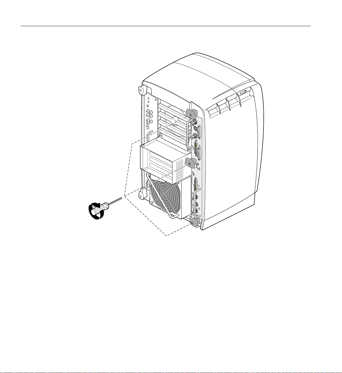
To remove the XIO Tri-Module, follow these steps:
1. Loosen the two captive screws in the XIO Tri-Module handles with the supplied
Phillips screwdriver until the screws are disconnected from the chassis (see
Figure 1-5).
Figure 1-5 Loosening the XIO Tri-Module Screws
8 007-4209-003

Preparing Your Workstation
Warning: The heat sinks on the XIO boards get very hot. Wait 5 minutes after
powering off your workstation before you remove the XIO Tri-Module. Test the
temperature of the heatsinks before handling any of the XIO boards.
2. Grasp the sliding handles and pull until the sliding portion of the XIO Tri-Module
protrudes about an inch from the chassis, as shown in Figure 1-6.
The sliding handles and XIO Tri-Module move out about one inch before the I/O
panels move.
Figure 1-6 Releasing the XIO Tri-Module
007-4209-003 9

1: Installing the DCD in a Single Head Octane2
3. Grasp the XIO Tri-Module by the immovable handle, and support the base of the
module as you remove it from the chassis, as shown in Figure 1-7.
Caution: Do not push on the sliding handles after you remove the XIO Tri-Module.
!
Later when you reinsert the Tri-Module, the sliding handles must protrude.
Figure 1-7 Removing the XIO Tri-Module
10 007-4209-003

Compression Connector Caution
Caution: The compression connector on the XIO Tri-Module is very delicate and easily
damaged. Do not touch or bump the gold bristled pad (see Figure 1-8). The connector is
!
on the side opposite the handle, as shown in Figure 1-9. Do not grab the back of the XIO
Tri-Module when you remove it, or the compression connector may be damaged.
Always place a cap on the compression connector after removing the XIO Tri-Module
(caps are included with your workstation). Before reinstalling the XIO Tri-Module in
your workstation, remove the cap from the compression connector.
Before you remove the XIO Tri-Module, read “Care and Cleaning of the Compression
Connector” in the Appendix section of your owner’s guide.
Preparing Your Workstation
Bristled pad
Figure 1-8 Identifying the Compression Connector
007-4209-003 11

1: Installing the DCD in a Single Head Octane2
Connecting the DCD
The DCD connects to the daughterboard slot on the XIO Tri-Module VPro graphics
board.
Caution: The following steps include detailed instructions for aligning the board. You
must follow these specific instructions to avoid damaging the connector pins. If you
!
attempt to connect the board before properly aligning it, the connector pins will likely be
damaged.
1. Place the XIO Tri-Module on a flat, antistatic surface with the VPro graphics board
I/O panel on the left side, as shown in Figure 1-9. An empty antistatic bag on your
desk works well.
When the XIO Tri-Module is out of the chassis, the sliding handles must protrude.
A label identifies each XIO slot (B on one side, C on the other). Slot B is the
daughterboard slot where you connect the DCD, as described later in this chapter.
Place cap
on compression connector
VPro Graphics Board
I/O panel
Daughterboard slot
Figure 1-9 Placing the XIO Tri-Module on Its Side
12 007-4209-003

Connecting the DCD
2. Place a cap on the XIO Tri-Module compression connector, as shown in Figure 1-9
and Figure 1-10.
Caps are included with your workstation.
Caution: To prevent damage to the connector, do not touch or bump the gold (front)
!
surface.
Caution - Do not touch
Figure 1-10 Placing a Cap on the XIO Compression Connector
007-4209-003 13

1: Installing the DCD in a Single Head Octane2
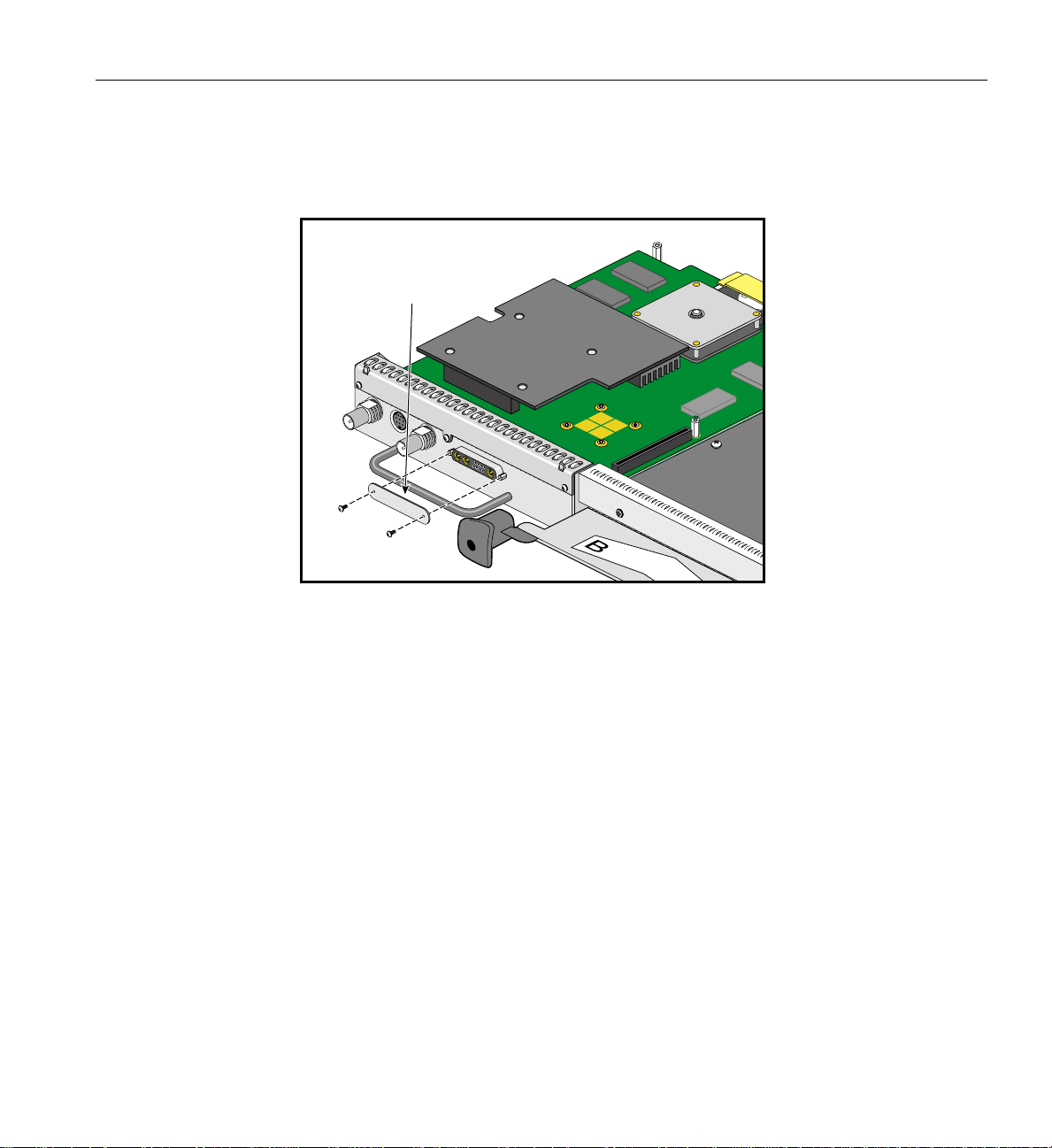
3. Remove the three screws from the VPro graphics board blank panel, as shown in
Figure 1-11. Save the screws for later in the installation.
Figure 1-11 Removing the Screws from the VPro Graphics Board Blank Panel
14 007-4209-003

Connecting the DCD
4. Remove the blank panel from the VPro graphics board, as shown in Figure 1-12.
Store the blank panel in a safe place. If you remove the DCD, you need to reinstall
the VPro graphics board blank panel.
Figure 1-12 Removing the VPro Graphics Board Blank Panel
5. Remove the nylon standoff from the bag of parts and install it as follows:
■ Remove the screw that is located behind the daughterboard connector on the
VPro graphics board (see A in Figure 1-13), and save it for later in the
installation.
■ Insert the nylon standoff into the hole from which you removed the screw (B).
■ Seat the nylon standoff by turning it clockwise (C), but do not overtighten.
007-4209-003 15

1: Installing the DCD in a Single Head Octane2
Standoff
Screw
Standoff
A
B
C
Figure 1-13 Installing the Standoff
6. Remove the DCD from its antistatic bag.
16 007-4209-003

Connecting the DCD
Caution: The following steps include detailed instructions for aligning the board. You
must follow these specific instructions to avoid damaging the connector pins. If you
!
attempt to connect the board before properly aligning it, the connector pins will likely be
damaged.
7. Align the DCD I/O panel with the VPro graphics board I/O panel as follows:
■ Line up the DCD’s two outside holes with the two outside holes on the VPro
graphics board (see A in Figure 1-14).
■ Place the DCD on top of the VPro graphics board.
■ Line up the two locator slots on the outside of the DCD with the locator tabs on
the outside of the VPro graphics board (B).
A
Align outside holes
Figure 1-14 Positioning the DCD
B
Place locator slots over locator tabs
8. Seat the DCD connector in the VPro graphics board daughterboard slot, as follows:
a. Push the top edge of the DCD I/O panel against the VPro graphics board I/O
panel (see A in Figure 1-15).
007-4209-003 17

1: Installing the DCD in a Single Head Octane2
Note: As you push the board forward, the connectors move into alignment and
partially seat without the assistance of downward pressure.
b. Press down on the top of the DCD I/O panel to fully seat its locator slots over
the VPro graphics board locator tabs (B).
c. Press down gently on the area above the DCD connector to make sure it is fully
seated (C). See Figure 1-16 for a side view seating of the board.
A
B
C
Figure 1-15 Seating the DCD On the VPro Graphics Board (front view)
Figure 1-16 shows a side view seating of the board.
18 007-4209-003

Connecting the DCD
Board not yet seated
Figure 1-16 Seating the DCD On the VPro Graphics Board (side view)
Board fully seated
Not seated
Partially seated
Fully seated
007-4209-003 19

1: Installing the DCD in a Single Head Octane2
Note: After you complete step 8, make sure the locator tabs at each end of the VPro
graphics board I/O panel protrude through the locator slots on each end of the DCD
I/O panel, as shown in Figure 1-17.
VPro Graphics Board locator tabs
Figure 1-17 VPro Locator Tabs Protrude through DCD Locator Slots
20 007-4209-003

Connecting the DCD
9. Secure the DCD to the VPro graphics board with the three screws you removed
from the blank panel, as shown in Figure 1-18.
Install the two outside screws first, then install the middle screw.
Note: Turn the screws until they are snug, but do not overtighten them.
Figure 1-18 Securing the DCD to the VPro Graphics Board
007-4209-003 21

1: Installing the DCD in a Single Head Octane2
10. Place the screw you removed from the VPro graphics board into the hole behind the
DCD connector (above the standoff), then tighten the screw by turning it clockwise,
as shown in Figure 1-19.
The DCD is now securely connected to the VPro graphics board.
Standoff screw
Figure 1-19 Securing the DCD to the Standoff
22 007-4209-003

Connecting the DCD
11. Remove the 13W3 cover and the two screws from the bag of parts.
12. Place the 13W3 cover over the VPro graphics board monitor port, with the padded
side of the cover facing the monitor port, as shown in Figure 1-20.
When a monitor is not connected to the VPro graphics board monitor port, you
must install the 13W3 cover to ensure that the system complies with local and
international EMC regulations.
13. Align the two outside holes of the 13W3 cover with the two thumbscrew holes on
the sides of the VPro graphics board monitor port.
13W3 cover
13W3 pad
VPro Graphics Board monitor port
Figure 1-20 Placing the 13W3 Cover over the VPro Graphics Board Monitor Port
007-4209-003 23

1: Installing the DCD in a Single Head Octane2
14. Insert a screw in each hole of the 13W3 cover, then tighten each screw to secure the
cover to the VPro graphics board, as shown in Figure 1-21.
Figure 1-21 Installing the 13W3 Cover
13W3 pad
24 007-4209-003

Reinstalling the XIO Tri-Module
Caution: To prevent damage to your workstation, reinstall the XIO Tri-Module with the
!
Graphics Board I/O panel aligned with the top of the workstation.
Follow these steps to reinstall the XIO Tri-Module:
1. Remove the cap from the XIO Tri-Module compression connector.
2. Slide the XIO Tri-Module into the guides on the top and bottom of the workstation.
3. Before you insert the XIO Tri-Module, make sure the sliding handles protrude in a
locked position from the I/O panels, as shown in Figure 1-22.
If the sliding handles are flush with the I/O panels, the XIO Tri-Module will stop
during insertion. Pull out the sliding handles until the sliding portion of the XIO
Tri-Module looks like Figure 1-22.
4. Grasp the immovable handle area with one hand while supporting the XIO
Tri-Module with the other, and slide the module into the chassis.
Use the immovable handle to push the XIO Tri-Module into a locked position. The
I/O panels are nearly flush with the workstation when properly inserted, but there
is a slight variation in the depth of the boards.
Reinstalling the XIO Tri-Module
5. Push the sliding handles until the sliding portion of the module is flush with the
workstation.
007-4209-003 25

1: Installing the DCD in a Single Head Octane2
Figure 1-22 Inserting the XIO Tri-Module
26 007-4209-003

Reinstalling the XIO Tri-Module
6. Tighten the captive screws in the sliding handles, as shown in Figure 1-23.
Figure 1-23 Tightening the XIO Tri-Module Screws
7. Remove the wrist strap.
8. Reconnect all cables to the XIO Tri-Module, except for the monitor cable.
You are finished installing your DCD.
Now go to Chapter 2 for instructions on connecting two monitors to the DCD.
007-4209-003 27

1: Installing the DCD in a Single Head Octane2
Removing the DCD
If you want to remove the DCD and connect a monitor to the VPro graphics board
monitor port, follow these steps:
1. Power off and prepare your workstation, as described earlier in this chapter.
2. Remove the XIO Tri-Module, as described earlier in this chapter.
3. Remove the DCD as follows (see Figure 1-24):
a. Remove the three screws that secure the DCD I/O panel to the VPro graphics
board I/0 panel.
b. Remove the standoff screw.
c. Remove the DCD and store it in an antistatic bag.
Note: As you remove the DCD, make sure its locator slots are completely detached
from the VPro graphics board locator tabs.
28 007-4209-003

Front screws
Removing the DCD
Standoff screw
Figure 1-24 Removing the DCD
4. Reinstall the VPro graphics board blank panel, as shown in Figure 1-25.
007-4209-003 29

1: Installing the DCD in a Single Head Octane2
Front screws
Figure 1-25 Reinstalling the VPro graphics board Blank Panel
30 007-4209-003
Removing the DCD
5. Remove the two screws securing the 13W3 cover to the VPro graphics board, then
remove the cover, as shown in Figure 1-26.
Remove
13W3 cover
Figure 1-26 Removing the 13W3 Cover
007-4209-003 31

1: Installing the DCD in a Single Head Octane2
6. Reinstall the XIO Tri-Module, as described earlier in this chapter.
7. Connect a monitor to the VPro graphics board monitor port, as shown in
Figure 1-27.
8. Connect one end of the monitor power cable to your workstation and the other end
to a 3-prong grounded electrical outlet.
9. Reconnect your workstation’s power cable.
10. Power on your workstation and monitor.
To monitor
Figure 1-27 Connecting a Monitor to the VPro graphics board
32 007-4209-003

Chapter 2
2. Installing the DCD in a Dual Head Octane2
This chapter shows you howto install the DCD inyour Silicon Graphics Octane orSilicon
Graphics Octane2 workstation containing Dual Head VPro graphics.
The instructions in this chapter focus on the installation of one DCD. To install a second
DCD, see “Installing a Second DCD” on page 64.
The following topics are covered:
• “Checking Your Shipment” on page 34
• “Checking Your Graphics Board” on page 35
• “Preparing Your Workstation” on page 36
• “Removing the Dual Head XIO Module” on page 40
• “Connecting the DCD” on page 44
• “Installing a Second DCD” on page 64
• “Reinstalling the Dual Head XIO Module” on page 66
• “Removing the DCD” on page 71
007-4209-003 33

2: Installing the DCD in a Dual Head Octane2
Checking Your Shipment
Make sure your shipment contains the items shown in Figure 2-1.
Wrist strap
Documentation
Bag of parts
(13W3 cover, screws,
and standoff)
Figure 2-1 DCD Shipment Components
DCD board
Reversible
screwdriver
DVI/VGA monitor cables
34 007-4209-003

Checking Your Graphics Board
To use the DCD, your Dual Head workstation must have VPro V12 graphics boards
installed. If you have a Single Head workstation, see Chapter 1, “Installing the DCD in a
Single Head Octane2”. Properly installed VPro V12 graphics boards ensure that you are
running the correct version of IRIX.
To verify that your system has VPro V12 graphics boards, follow these steps:
1. Open a UNIX shell.
2. At the prompt, enter hinv
You will see output similar to the following:
2 250 MHZ IP30 Processors
CPU: MIPS R10000 Processor Chip Revision: 3.4
FPU: MIPS R10010 Floating Point Chip Revision: 0.0
Main memory size: 512 Mbytes
Xbow ASIC: Revision 1.4
Instruction cache size: 32 Kbytes
Data cache size: 32 Kbytes
Secondary unified instruction/data cache size: 1 Mbyte
Integral SCSI controller 0: Version QL1040B (rev. 2), single ended
Disk drive: unit 1 on SCSI controller 0
Integral SCSI controller 1: Version QL1040B (rev. 2), single ended
IOC3 serial port: tty1
IOC3 serial port: tty2
IOC3 parallel port: plp-1
Graphics board: V12
Graphics board: V12
Integral Fast Ethernet: ef0, version 1, pci 2
Iris Audio Processor: version RAD revision 12.0, number 1
Checking Your Graphics Board
3. Look for the following two lines describing your graphics boards:
Graphics board: V12
Graphics board: V12
If only one graphics board is listed, you may have a Single Head system. In that
case, see Chapter 1, “Installing the DCD in a Single Head Octane2”.
If two boards are shown, but they are not listed as V12, you cannot use the DCD.
For more information, contact your authorized SGI sales representative.
007-4209-003 35

2: Installing the DCD in a Dual Head Octane2
Preparing Your Workstation
This section describes preparing your workstation for the removal of the Dual Head XIO
Module. This preparation consists of:
• “Powering Off Your Workstation” on page 37
• “Removing the Cables from the Dual Head XIO Module” on page 38
• “Attaching the Wrist Strap” on page 39
36 007-4209-003

Powering Off Your Workstation
To power off your workstation, follow these steps:
1. Open the cover and press the power button to power off your workstation (see A in
Figure 2-2).
2. Unplug the power cable (B).
3. Press the monitor power switch to power off your monitor (C).
4. Wait 5 minutes before removing the Dual Head XIO Module.
Power cable
Preparing Your Workstation
A
B
Power button
C
Power switch
Figure 2-2 Powering Off Your Workstation
Warning: The heat sinks on the XIO boards get very hot. Wait 5 minutes after
powering off your workstation before you remove the Dual Head XIO Module. Test
the temperature of the heatsinks before handling any of the XIO boards.
007-4209-003 37

2: Installing the DCD in a Dual Head Octane2
R
R
L
L
UNLATCH
LATCH
Swap
Ready
Swap
Ready
Removing the Cables from the Dual Head XIO Module
Remove all the cables from the Dual Head XIO Module. Only the monitor cables on the
VPro graphics boards are shown in Figure 2-3.
Note: The following illustrations show a workstation with a PCI module installed. Your
workstation may not have a PCI module, but the DCD installation is the same.
G
e
n
lo
c
k
S
w
a
p
R
e
L
a
d
y
R
L
A
T
C
H
U
N
L
A
T
C
H
R
L
S
w
a
p
R
e
a
d
y
G
e
n
lo
c
k
Primary
monitor
Secondary
monitor
Figure 2-3 Removing the Monitor Cables
38 007-4209-003

Attaching the Wrist Strap
Caution: The internal components are extremely sensitive to static electricity; always
!
wear the wrist strap when you handle parts inside your workstation.
To attach the wrist strap, follow these steps:
1. Unroll the first two folds of the band (see A in Figure 2-4).
2. Wrap the exposed adhesive side firmly around your wrist, unroll the rest of the
3. Attach the copper foil to any exposed electrical ground, such as a metal part of the
Preparing Your Workstation
band, and then peel the liner from the copper foil at the opposite end (B).
workstation (C).
Unroll
A
Genlock
Swap
L
Ready
R
B
LATCH
UNLATCH
R
C
L
Swap
Ready
Genlock
Figure 2-4 Attaching the Wrist Strap
007-4209-003 39

2: Installing the DCD in a Dual Head Octane2
Removing the Dual Head XIO Module
You must remove your workstation’s Dual Head XIO Module so you can connect the
DCD to the daughterboard slot on the VPro graphics board. Before removing the Dual
Head XIO Module, you must power off your workstation, wait 5 minutes to allow the
heat sinks to cool, and attach the wrist strap, as described in the previous sections.
To remove the Dual Head XIO Module, follow these steps:
1. Loosen the two captive screws in the Dual Head XIO Module handles with the
supplied Phillips screwdriver until the screws are disconnected from the chassis
(see Figure 2-5).
Genlock
Swap
Ready
L
R
LATCH
UNLATCH
R
L
Swap
Ready
Genlock
Figure 2-5 Loosening the Dual Head XIO Module Screws
40 007-4209-003

Removing the Dual Head XIO Module
Warning: The heat sinks on the XIO boards get very hot. Wait 5 minutes after
powering off your workstation before you remove the Dual Head XIO Module. Test
the temperature of the heat sinks before handling any of the XIO boards.
2. Grasp the center plastic knob and pull until the knob protrudes about an inch (2.5
cm) from the chassis, as shown in Figure 2-6.
The knob moves out about an inch (2.5 cm) before the I/O panel moves.
Genlock
Swap
Ready
L
R
LATCH
UNLATCH
R
L
Swap
Ready
Genlock
Figure 2-6 Releasing the Dual Head XIO Module
007-4209-003 41

2: Installing the DCD in a Dual Head Octane2
3. Grasp the handles on the Dual Head XIO Module and slide the module out of the
chassis, as shown in Figure 2-7. You may also want to support the bottom of the
module while sliding it out.
The center plastic knob protrudes when the Dual Head XIO Module is out of the
chassis.
Note: Do not push on the knob after you have removed the Dual Head XIO Module
from the chassis. The module locks to the workstation only if the knob is protruding.
4. Place the Dual Head XIO Module on a flat, antistatic surface. An empty antistatic
bag on your desk works well.
Genlock
Swap
Ready
L
R
LATCH
UNLATCH
R
L
Swap
Ready
Genlock
Figure 2-7 Removing the Dual Head XIO Module
42 007-4209-003

Compression Connector Caution
Caution: The compression connector on the Dual Head XIO Module is very delicate and
!
easily damaged. Do not touch or bump the gold bristled pad (see Figure 2-8). The
connector ison the side opposite the handle, as shown in Figure 2-9. Do not grab the back
of the Dual Head XIO Module when you remove it, or the compression connector may
be damaged.
Always place a cap on the compression connector after removing the Dual Head XIO
Module. Caps are included with your workstation. Before reinstalling the Dual Head
XIO Module in your workstation, remove the cap from the compression connector.
Before you remove the Dual Head XIO Module, read Appendix A, “Care and Cleaning
of Compression Connectors”.
Removing the Dual Head XIO Module
Bristled pad
Figure 2-8 Identifying the Compression Connector
007-4209-003 43

2: Installing the DCD in a Dual Head Octane2
Connecting the DCD
The DCD connects to the daughterboard slot on one of the Dual Head XIO Module VPro
graphics boards.
1. Place the Dual Head XIO Module on a flat, antistatic surface, as shown in
Figure 2-9. An empty antistatic bag on your desk works well.
When the Dual Head XIO Module is out of the chassis, the center plastic knob must
protrude.
Place caps on
compression connectors
Figure 2-9 Placing the Dual Head XIO Module on Its Side
44 007-4209-003

Connecting the DCD
2. Place caps on the Dual Head XIO Module compression connectors, as shown in
Figure 2-9 and Figure 2-10. Spare compression connector caps are included with
your workstation.
Caution: To prevent damage to the connector, do not touch or bump the gold (front)
!
surface.
Caution - Do not touch
Figure 2-10 Placing a Cap on the XIO Compression Connector
007-4209-003 45

2: Installing the DCD in a Dual Head Octane2
3. Loosen the center plastic knob clamping screw, as shown in Figure 2-11. There is no
need to remove this screw—loosening it about one turn is sufficient.
Figure 2-11 Loosening the Center Plastic Knob Clamping Screw
Clamping screw
location
46 007-4209-003

Connecting the DCD
4. Turn the Dual Head XIO Module over and remove the center plastic knob retaining
screw, as shown in Figure 2-12. Save the retaining screw for later in the installation.
Note: You may need to push the knob in slightly to be able to reach the screw with the
screwdriver.
Retaining screw
location
Figure 2-12 Removing the Center Plastic Knob Retaining Screw
5. Turn the Dual Head XIO Module back over, remove the center plastic knob, and
save it for later in the installation.
007-4209-003 47

2: Installing the DCD in a Dual Head Octane2
6. Remove the four nuts and lock washers from the BNC connectors, as shown in
Figure 2-13. Save the nuts and lock washers for later in the installation.
Note: These nuts are most easily removed using a socket wrench with a deep 9/16-inch
socket.
Figure 2-13 Removing the Nuts and Lock Washers from the Graphics Board I/O Panel
48 007-4209-003

Connecting the DCD
7. Using a 3/16-inch wrench, remove the four jackscrews from the 13W3 connectors,
as shown in Figure 2-14. Save the jackscrews for later in the installation.
Figure 2-14 Removing the Jackscrews from the Graphics Board I/O Panel
007-4209-003 49

2: Installing the DCD in a Dual Head Octane2
8. Loosen (but do not remove) the four Phillips-head screws (items A, B, C, and D in
Figure 2-15) that hold the two plastic heat-sink stabilizer brackets.
A
B
C
D
Figure 2-15 Loosening the Heat-Sink Stabilizer Bracket Retaining Screws on the Graphics
Board I/O Panel
50 007-4209-003

Connecting the DCD
9. Using your index finger, lift the upper-right plastic heat-sink stabilizing bracket
away from the heat sink. This is the bracket held in by screws C and D in
Figure 2-15.
10. While holding the bracket up, gently remove the I/O panel from the Dual Head XIO
Module, as shown in Figure 2-16.
Figure 2-16 Removing the Dual Head XIO Module I/O Panel
11. As you remove the I/O panel, be careful not to lose the rubber gaskets located
between the I/O panel and the VPro graphics boards. Save the gaskets for later in
the installation.
007-4209-003 51

2: Installing the DCD in a Dual Head Octane2
12. Remove the screw holding the DCD blanking panel to the Dual Head XIO Module
I/O panel, as shown in Figure 2-17, and remove the blanking panel.
Figure 2-17 Removing the DCD Blanking Panel
13. Remove the male-to-female nylon standoff from the bag of parts. If the kit includes a
female-to-female nylon standoff, it will not be used in this installation. Install the
standoff as follows:
a. Remove the screw that is located behind the daughterboard connector on the
VPro graphics board (see A in Figure 2-18), and save it for later in the
installation.
b. Insert the nylon standoff into the hole from which you removed the screw (B in
Figure 2-18).
c. Seat the nylon standoff by turning it clockwise (C in Figure 2-18), but do not
over-tighten it to avoid stripping the delicate plastic threads.
52 007-4209-003

Connecting the DCD
Screw
Standoff
A
B
C
Figure 2-18 Installing the Nylon Standoff
007-4209-003 53

2: Installing the DCD in a Dual Head Octane2
14. Remove the DCD from its antistatic bag.
15. Align the DCD over the VPro graphics board, as shown in Figure 2-19.
Figure 2-19 Positioning the DCD
16. Making sure that the connectors are properly aligned, gently press the DCD down
onto the connector on the VPro graphics board.
54 007-4209-003

Connecting the DCD
17. Place the screw you removed from the VPro graphics board into the hole behind the
DCD connector (above the nylon standoff), and then gently tighten the screw by
turning it clockwise, as shown in Figure 2-20. When the screw begins to get tight,
unscrew it about two turns, leaving the DCD slightly loose (you will tighten it the
rest of the way later).
Standoff screw
Figure 2-20 Securing the DCD to the Nylon Standoff
18. If you will install a second DCD at this time, skip to the instructions in “Installing a
Second DCD” on page 64.
007-4209-003 55

2: Installing the DCD in a Dual Head Octane2
19. Place the two rubber gaskets over the VPro graphics board connectors, as shown in
Figure 2-21.
20. Place the two new rubber gaskets over the two DCD connectors, as shown in
Figure 2-21.
21. Using your index finger, lift the upper-right plastic heat-sink stabilizing bracket.
This is the bracket held in by screws C and D in Figure 2-15.
22. While holding the bracket up, gently install the I/O panel on the Dual Head XIO
Module, as shown in Figure 2-21. Make sure that the I/O panel is installed in the
correct orientation.
Figure 2-21 Installing the Dual Head XIO Module I/O Panel
56 007-4209-003

Connecting the DCD
23. Install the four nuts and lock washers on the BNC connectors, as shown in
Figure 2-22, but do not tighten them yet.
Note: These nuts are most easily installed using a socket wrench with a deep 9/16-inch
socket.
Figure 2-22 Installing the Nuts and Lock Washers on the Graphics Board I/O Panel
007-4209-003 57

2: Installing the DCD in a Dual Head Octane2
24. Install the four jackscrews on the 13W3 connectors, as shown in Figure 2-23, but do
not tighten them yet.
25. Install the four new jackscrews on the DCD DVI connectors, as shown in
Figure 2-23, but do not tighten them yet.
Figure 2-23 Installing the Jackscrews on the Graphics Board I/O Panel
58 007-4209-003

Connecting the DCD
26. Turn the Dual Head Module over and insert the center plastic knob into the I/O
panel, as shown in Figure 2-24. Make sure that the knob is installed in the correct
orientation. One way of ensuring this is to make sure the spring-loaded screw in the
center plastic knob is aligned over the threaded hole in the I/O panel.
27. Install and tighten the center plastic knob retaining screw, as shown in Figure 2-24.
Retaining screw
location
Figure 2-24 Installing the Center Plastic Knob Retaining Screw
007-4209-003 59

2: Installing the DCD in a Dual Head Octane2
28. Turn the Dual Head XIO Module back over and tighten the center plastic knob
clamping screw, as shown in Figure 2-25.
29. Pull the center plastic knob to make sure it is fully extended. You may have had to
push it in slightly in order to reach the retaining screw, but you should pull it back
out now.
Clamping screw
location
Figure 2-25 Tightening the Center Plastic Knob Clamping Screw
60 007-4209-003

Connecting the DCD
30. Tighten the four Phillips-head screws holding the two plastic heat-sink stabilizer
brackets, as shown in Figure 2-15 (items A, B, C, and D).
31. Tighten the four jackscrews on the 13W3 connectors.
32. Tighten the four jackscrews on the DCD DVI connectors.
33. Tighten the four nuts on the BNC connectors.
34. Gently tighten the screw in the hole behind the DCD connector (above the nylon
standoff), as shown in Figure 2-20.
007-4209-003 61

2: Installing the DCD in a Dual Head Octane2
35. Remove the 13W3 cover and the two screws from the bag of parts.
36. Place the 13W3 cover over the VPro graphics board monitor port, with the padded
side of the cover facing the monitor port, as shown in Figure 2-26.
When a monitor is not connected to the VPro graphics board monitor port, you
must install the 13W3 cover to ensure that the system complies with local and
international EMC regulations.
37. Align the two outside holes of the 13W3 cover with the two thumbscrew holes on
the sides of the VPro graphics board monitor port.
13W3 cover
13W3 pad
VPro graphics board monitor port
Figure 2-26 Placing the 13W3 Cover over the VPro Graphics Board Monitor Port
62 007-4209-003

Connecting the DCD
38. Insert a screw in each hole of the 13W3 cover, and then tighten each screw to secure
the cover to the VPro graphics board, as shown in Figure 2-27.
13W3 pad
Figure 2-27 Installing the 13W3 Cover
007-4209-003 63

2: Installing the DCD in a Dual Head Octane2
Installing a Second DCD
An Octane2 workstation with Dual Head V12 VPro graphicsmay be upgraded to contain
either one or two DCDs. The installation of the first DCD is described in the preceding
sections of this chapter. The installation of a second DCD is described in this section.
A Dual Head system with one DCD allows the connection of a total of three monitors:
two on the primary graphics head (the one toward the top of the system), and one on the
secondary graphics head (the one toward the bottom of the system).
A Dual Head system with two DCDs allows the connection of a total of four monitors:
two on the primary graphics head (the one toward the top of the system), and two on the
secondary graphics head (the one toward the bottom of the system).
To install a second DCD, follow these steps:
If youwill install a second DCD at the same time as the first DCD, and thus have the Dual
Head XIO Module out of the Octane2 chassis and have the I/O panel removed, skip to
step 4.
1. Prepare the workstation as described in “Preparing Your Workstation” on page 36.
2. Remove the Dual Head XIO Module, as described in “Removing the Dual Head XIO
Module” on page 40.
3. Remove the I/O panel, as described in steps 1 through 11 (on page 44 through
page 51).
Before performing step 7 (on page 49), you will first need to remove the two screws
that hold a cover over the 13W3 connector. After performing step 7, you will then
also remove the four jackscrews on the first DCD.
In step 11 (on page 51), also remove the two rubber gaskets on DVI connectors, and
save them for later.
4. Turn the Dual Head XIO Module over, exposing the VPro graphics board on which
there is not yet a DCD installed.
5. Install the DCD as described in steps 13 through 17 (on page 52 through page 55).
6. Reinstall the I/O panel as described in steps 19 through 34 (on page 56 through
page 61).
Because at this point both VPro graphics boards have DCDs attached, it no longer
matters which board ends up at the top, as described in step 21 (on page 56).
64 007-4209-003

Installing a Second DCD
In step 25 (on page 58), you will install eight new jackscrews on the DVI connectors.
Steps 27 and 28 (on page 59 and page 60) will be reversed. Tighten the clamping
screw first, and then turn the module over and install and tighten the retaining
screw.
7. Install covers over both 13W3 connectors, as described in steps 35 through 38 (on
page 62 through page 63).
8. Reinstall the Dual Head XIO Module, as described in “Reinstalling the Dual Head
XIO Module” on page 66.
007-4209-003 65

2: Installing the DCD in a Dual Head Octane2
Reinstalling the Dual Head XIO Module
Follow the steps in this section to reinstall the Dual Head XIO Module.
66 007-4209-003

Swap
Ready
Reinstalling the Dual Head XIO Module
Dual Head XIO module
Genlock
L
Slots A & B - primary head
R
LATCH
UNLATCH
L
Swap
Ready
R
Genlock
XIO Module center knob
Slots C & D - secondary head
Octane2 Dual Head with Dual Channel
Figure 2-28 Placing the Primary Head Graphics Boards toward the Top of the Workstation
Note: Be sure to install the Dual Head XIO Module in the orientation shown in
Figure 2-28. This orientation can be confirmed by ensuring that the silk-screened labels
on the I/O panel are right-side up, and that the center plastic knob is in the orientation
shown in Figure 2-28.
007-4209-003 67

2: Installing the DCD in a Dual Head Octane2
1. Remove the cap from the Dual Head XIO Module compression connectors.
2. Slide the Dual Head XIO Module into the guides on the top and bottom of the
workstation, as shown in Figure 2-29. Be sure the module is oriented correctly, as
shown in Figure 2-28.
Before you insert the Dual Head XIO Module, make sure the center plastic knob
protrudes from the I/O panel, as shown in Figure 2-29.
If the center plastic knob is flush with the I/O panel, the Dual Head XIO Module
will stop before it is fully inserted. If this happens, pull the entire assembly out of
the slot about an inch (2.5 cm), pull out the center knob, and then continue inserting
the Dual Head XIO Module into the chassis.
Figure 2-29 Inserting the Dual Head Module with DCD
68 007-4209-003

Reinstalling the Dual Head XIO Module
Genlock
Swap
Ready
L
R
LATCH
UNLATCH
R
L
Swap
Ready
Genlock
Figure 2-30 Latching the Dual Head XIO Module
3. Grasp the center plastic knob, as shown in Figure 2-30, and push it into place
against the I/O panel.
007-4209-003 69
2: Installing the DCD in a Dual Head Octane2
Genlock
Swap
Ready
L
R
LATCH
UNLATCH
R
L
Swap
Ready
Genlock
Figure 2-31 Replacing the Dual Head XIO Module Screws
4. Gently tighten each of the three captive screws in the plastic knobs, as shown in
Figure 2-31. Be careful not to cross-thread these screws and do not over-tighten
them.
5. Remove the wrist strap.
You have finished installing your DCD.
Proceed to Chapter 3, “Connecting Monitors to the DCD,” for instructions on connecting
two monitors to the DCD.
70 007-4209-003

Removing the DCD
If you want to remove the DCD and connect a monitor to the VPro graphics board
monitor port, follow these steps:
1. Prepare your workstation, as described in “Preparing Your Workstation” on
2. Remove the Dual Head XIO Module, as described in “Removing the Dual Head XIO
3. Remove the two screws securing the 13W3 cover to the VPro graphics board, and
Removing the DCD
page 36.
Module” on page 40.
then remove the cover, as shown in Figure 2-32.
13W3 cover
13W3 pad
VPro graphics board monitor port
Figure 2-32 Removing the 13W3 Cover
007-4209-003 71

2: Installing the DCD in a Dual Head Octane2
4. Loosen the center plastic knob clamping screw, as shown in Figure 2-33. There is no
need to remove this screw—loosening it about one turn is sufficient.
Figure 2-33 Loosening the Center Plastic Knob Clamping Screw
Clamping screw
location
72 007-4209-003
Removing the DCD
5. Turn the Dual Head XIO Module over and remove the center plastic knob retaining
screw, as shown in Figure 2-34. Save the retaining screw for later in the installation.
Note: You may need to push in the knob slightly to be able to reach the screw with the
screwdriver.
Retaining screw
location
Figure 2-34 Removing the Center Plastic Knob Retaining Screw
6. Turn the Dual Head XIO Module back over, remove the center plastic knob, and
save it for later in the installation.
007-4209-003 73

2: Installing the DCD in a Dual Head Octane2
7. Remove the four nuts and lock washers from the BNC connectors, as shown in
Figure 2-35. Save the nuts and lock washers for later in the installation.
Note: These nuts are most easily removed using a socket wrench with a deep 9/16-inch
socket.
Figure 2-35 Removing the Nuts and Lock Washers from the Graphics Board I/O Panel
74 007-4209-003

Removing the DCD
8. Remove the four jackscrews from the 13W3 connectors, as shown in Figure 2-36.
Save the jackscrews for later in the installation.
Figure 2-36 Removing the Jackscrews from the Graphics Board I/O Panel
007-4209-003 75

2: Installing the DCD in a Dual Head Octane2
9. Loosen (but do not remove) the four Phillips-head screws (items A, B, C, and D in
Figure 2-37) that hold the two plastic heat-sink stabilizer brackets.
A
B
C
D
Figure 2-37 Loosening the Heat-Sink Stabilizer Bracket Retaining Screws on the Graphics
Board I/O Panel
76 007-4209-003

Removing the DCD
10. While lifting the plastic heat-sink stabilizing brackets, gently remove the I/O panel
from the Dual Head XIO Module, as shown in Figure 2-38.
Figure 2-38 Removing the Dual Head XIO Module I/O Panel
11. As you remove the I/O panel, make sure not to lose the rubber gaskets located
between the I/O panel and the VPro graphics boards. Save the two large gaskets for
later in the installation. Store the two small gaskets in the antistatic bag in which
you will be placing the DCD.
007-4209-003 77

2: Installing the DCD in a Dual Head Octane2
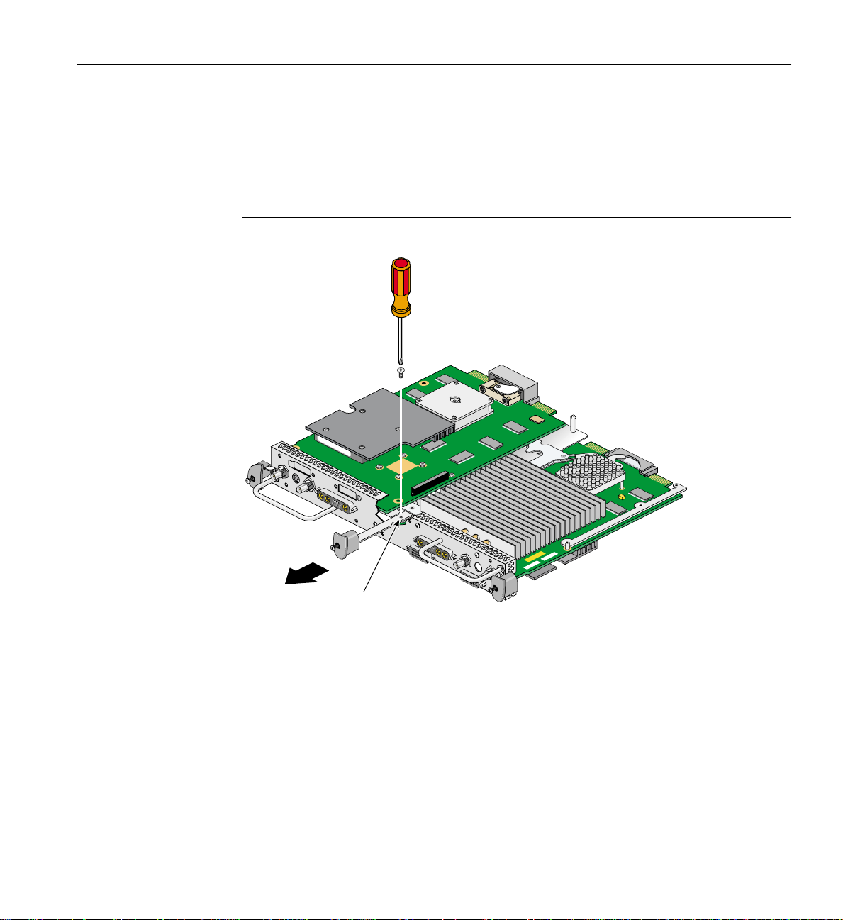
12. Remove the screw holding the DCD to the nylon standoff, as shown in Figure 2-39.
Save the screw for later in the installation.
Standoff screw
Figure 2-39 Removing the DCD Retaining Screw
78 007-4209-003

Removing the DCD
13. Lift the DCD straight up from the VPro graphics board, as shown in Figure 2-40.
14. Place the DCD on an antistatic bag.
Figure 2-40 Removing the DCD
007-4209-003 79

2: Installing the DCD in a Dual Head Octane2
15. Remove the nylon standoff that is located behind the daughterboard connector on
the VPro graphics board (see Figure 2-41), and store it with the DCD.
Standoff
Figure 2-41 Removing the Nylon Standoff
80 007-4209-003

Removing the DCD
16. Install the screw you removed in step 12 into the hole just vacated by the nylon
standoff, as shown in Figure 2-42.
Screw
Figure 2-42 Installing the Mounting Screw
007-4209-003 81

2: Installing the DCD in a Dual Head Octane2
17. Retrieve the DCD blanking panel that was removed when the DCD was installed,
and place it in the Dual Head XIO Module I/O board, as shown in Figure 2-43.
18. Install the blanking panel retaining screw, as shown in Figure 2-43.
Figure 2-43 Installing the DCD Blanking Panel
82 007-4209-003
 Loading...