


SGI® Altix® XE320 System User’s Guide
007-5466-001

COPYRIGHT
© 2008 SGI. All rights reserved; provided portions may be cop yright in third parties, as indicated elsewhere herein. No permission is granted to copy , distribute,
or create derivative works from the contents of this electronic documentation in any manner, in whole or in part, without the prior written permission of SGI.
LIMITED RIGHTS LEGEND
The software described in this document is “commercial computer software” provided with restricted rights (except as to included open/free source) as specified
in the F AR 52.227-19 and/or the DFAR 227.7202, or successive sections. Use beyond license provisions is a violation of worldwide intellectual property laws,
treaties and conventions. This document is provided with limited rights as defined in 52.227-14.
The electronic (software) version of this document was developed at private expense; if acquired under an agreement with the USA government or any
contractor thereto, it is acquired as “commercial computer software” subject to the provisions of its applicable license agreement, as specified in (a) 48 CFR
12.212 of the FAR; or, if acquired for Department of Defense units, (b) 48 CFR 227-7202 of the DoD FAR Supplement; or sections succeeding thereto.
Contractor/manufacturer is SGI, 1140 E. Arques Avenue, Sunnyvale, CA 94085.
TRADEMARKS AND ATTRIBUTIONS
Altix, SGI, and the SGI logo are registered trademarks and SGI ProPack is a trademark of SGI in the United States and/or other countries worldwide.
InfiniBand is a registered trademark of the InfiniBand Trade Association. Intel, Itanium, and Xeon are trademarks or registered trademarks of Intel Corporation
or its subsidiaries in the United States and other countries. Internet Explorer is a registered trademark of Microsoft
Corporation. Java and Java Virtual Machine
are trademarks or registered trademarks of Sun Microsystems, Inc. Linux is a registered trademark of Linus Torvalds, used with permission by SGI. LSI Logic
is a registered trademark of LSI Logic Corporation. Novell and Novell Netware are registered trademarks of Novell Inc. Phoenix and PhoenixBIOS are
registered trademarks of Phoenix Technologies Ltd. Red Hat and all Red Hat-based trademarks are trademarks or registered trademarks of Red Hat, Inc. in the
United States and other countries. SUSE LINUX and the SUSE logo are registered trademarks of Novell, Inc. UNIX is a registered trademark in the
United
States and other countries, licensed exclusively through X/Open Company, Ltd.
All other trademarks mentioned herein are the property of their respective owners.
Adaptec, HostRAID, and the Adaptec logo are registered trademarks of Adaptec Inc.

Record of Revision
Version Description
001 February 2008
Initial publication.
007-5466-001 iii


Contents
Contents
About This Guide . . . . . . . . . . . . . . . . . . . . . . xxiii
Audience. . . . . . . . . . . . . . . . . . . . . . . . . xxiii
Important Information . . . . . . . . . . . . . . . . . . . . . xxiii
Chapter Descriptions . . . . . . . . . . . . . . . . . . . . . xxiv
Related Publications. . . . . . . . . . . . . . . . . . . . . . .xxv
Conventions . . . . . . . . . . . . . . . . . . . . . . . . xxvi
Product Support . . . . . . . . . . . . . . . . . . . . . . . xxvi
Reader Comments . . . . . . . . . . . . . . . . . . . . . . xxvii
1 Introduction . . . . . . . . . . . . . . . . . . . . . . . . 1
Node Board Features . . . . . . . . . . . . . . . . . . . . . . 4
Processors . . . . . . . . . . . . . . . . . . . . . . . . 4
Memory. . . . . . . . . . . . . . . . . . . . . . . . . 4
Serial ATA (SATA) . . . . . . . . . . . . . . . . . . . . . 4
Serial Attached SCSI (SAS) and RAID Support . . . . . . . . . . . . . . 6
PCIe Expansion Slots . . . . . . . . . . . . . . . . . . . . . 6
Ethernet Ports . . . . . . . . . . . . . . . . . . . . . . . 6
Onboard Controllers/Ports . . . . . . . . . . . . . . . . . . . . 6
ATI Graphics Controller . . . . . . . . . . . . . . . . . . . . 6
Other Features . . . . . . . . . . . . . . . . . . . . . . . 6
Server Chassis Features . . . . . . . . . . . . . . . . . . . . . . 7
System Power . . . . . . . . . . . . . . . . . . . . . . . 7
SATA/SAS Backplane/Drives . . . . . . . . . . . . . . . . . . . 7
Control Panel . . . . . . . . . . . . . . . . . . . . . . . 7
Rear I/O Panel . . . . . . . . . . . . . . . . . . . . . . . 8
Cooling System. . . . . . . . . . . . . . . . . . . . . . . 8
007-5466-001 v

Contents
System Security and Pre-Installed Linux Operating Systems . . . . . . . . . . . . 8
2 Server Installation . . . . . . . . . . . . . . . . . . . . . . . 9
Unpack the System . . . . . . . . . . . . . . . . . . . . . . . 9
Prepare for Setup . . . . . . . . . . . . . . . . . . . . . . 9
Choose a Setup Location . . . . . . . . . . . . . . . . . . . . 9
Warnings and Precautions . . . . . . . . . . . . . . . . . . . . . 10
Rack Precautions . . . . . . . . . . . . . . . . . . . . . . 10
Server Precautions . . . . . . . . . . . . . . . . . . . . . . 11
Rack Mounting Considerations . . . . . . . . . . . . . . . . . . . . 11
Ambient Operating Temperature . . . . . . . . . . . . . . . . . . 11
Reduced Airflow . . . . . . . . . . . . . . . . . . . . . . 11
Mechanical Loading. . . . . . . . . . . . . . . . . . . . . . 11
Circuit Overloading . . . . . . . . . . . . . . . . . . . . . . 12
Reliable Ground . . . . . . . . . . . . . . . . . . . . . . . 12
Install the System into a Rack . . . . . . . . . . . . . . . . . . . . 12
Identify the Sections of the Rack Rails . . . . . . . . . . . . . . . . . 12
Install the Rails . . . . . . . . . . . . . . . . . . . . . . . 13
Locking Tabs . . . . . . . . . . . . . . . . . . . . . . . 16
Install the Server in a Rack . . . . . . . . . . . . . . . . . . . . 16
Install the Server in a Third-party Rack. . . . . . . . . . . . . . . . . 18
Check the Node Board Setup. . . . . . . . . . . . . . . . . . . . . 21
Access the Inside of the Chassis. . . . . . . . . . . . . . . . . . . 21
Check the CPUs (processors) . . . . . . . . . . . . . . . . . . . 22
Check the System Memory . . . . . . . . . . . . . . . . . . . . 22
Install Expansion PCIe Cards . . . . . . . . . . . . . . . . . . . 23
Check all Cable Connections and Airflow . . . . . . . . . . . . . . . . 23
Check the Drive Bay Setup . . . . . . . . . . . . . . . . . . . . 23
Check the SATA/SAS Drives . . . . . . . . . . . . . . . . . . 23
Check the Airflow . . . . . . . . . . . . . . . . . . . . . 23
Supply Power to the System . . . . . . . . . . . . . . . . . . 23
3 Controls and Indicators . . . . . . . . . . . . . . . . . . . . . 25
Controls . . . . . . . . . . . . . . . . . . . . . . . . . . 25
vi 007-5466-001

Contents
Indicators . . . . . . . . . . . . . . . . . . . . . . . . . 26
Drive Carrier Indicators . . . . . . . . . . . . . . . . . . . . 27
4 Advanced Node Board Setup . . . . . . . . . . . . . . . . . . . . 29
Handling the Node Board . . . . . . . . . . . . . . . . . . . . . 29
ESD Precautions . . . . . . . . . . . . . . . . . . . . . . 30
Unpacking . . . . . . . . . . . . . . . . . . . . . . . . 30
Node Board Installation . . . . . . . . . . . . . . . . . . . . . . 31
Connect the Power Cables . . . . . . . . . . . . . . . . . . . . 32
Connecting the Control Panel . . . . . . . . . . . . . . . . . . . 34
I/O Ports . . . . . . . . . . . . . . . . . . . . . . . . . . 35
Processor and Heatsink Installation and Removal . . . . . . . . . . . . . . . 35
Install a Processor . . . . . . . . . . . . . . . . . . . . . . 36
Install a Heatsink . . . . . . . . . . . . . . . . . . . . . . 40
Remove the Heatsink . . . . . . . . . . . . . . . . . . . . . 41
Replace the Thermal Interface Material . . . . . . . . . . . . . . . . 42
Removing TIM from a Processor . . . . . . . . . . . . . . . . . 42
Removing TIM from a Heatsink . . . . . . . . . . . . . . . . . 46
Remove the Processor . . . . . . . . . . . . . . . . . . . . . 48
Install Memory . . . . . . . . . . . . . . . . . . . . . . . . 50
Memory Layout. . . . . . . . . . . . . . . . . . . . . . . 50
Constraints for DIMM Pairs . . . . . . . . . . . . . . . . . . . 51
Performance Optimization . . . . . . . . . . . . . . . . . . . . 52
Memory Sparing Mode . . . . . . . . . . . . . . . . . . . . . 53
Memory Mirroring Mode . . . . . . . . . . . . . . . . . . . . 53
Mirroring Mode Upgrade . . . . . . . . . . . . . . . . . . . . 54
Install DIMMs . . . . . . . . . . . . . . . . . . . . . . . 54
Install or Remove the Air Shroud . . . . . . . . . . . . . . . . . . . 57
Node Board Component Locations . . . . . . . . . . . . . . . . . . . 58
Add PCIe Expansion Cards . . . . . . . . . . . . . . . . . . . . . 59
Install a PCIe Expansion Card . . . . . . . . . . . . . . . . . . . 59
Node Board Jumpers and Connectors . . . . . . . . . . . . . . . . . . 61
Node Board Connector Pin Definitions . . . . . . . . . . . . . . . . . . 63
ATX Power Connector Pin Definitions . . . . . . . . . . . . . . . . 64
007-5466-001 vii

Contents
Auxiliary Power Connector Pin Definitions (JP10). . . . . . . . . . . . . . 64
PW_ON Switch Pin Definitions (JF1) . . . . . . . . . . . . . . . . . 65
Reset Switch Pin Definitions (JF1) . . . . . . . . . . . . . . . . . . 65
Overheat/Fan Pin Definitions (JF1) . . . . . . . . . . . . . . . . . . 65
NIC2 LED Pin Definitions (JF1) . . . . . . . . . . . . . . . . . . 66
NIC1 LED Pin Definitions (JF1) . . . . . . . . . . . . . . . . . . 66
HDD LED Pin Definitions (JF1) . . . . . . . . . . . . . . . . . . 66
Power On LED Pin Definitions (JF1) . . . . . . . . . . . . . . . . . 67
NMI Switch Pin Definitions (JF1) . . . . . . . . . . . . . . . . . . 67
Fan Connector Pin Definitions (Fan1/2 - Fan7/8) . . . . . . . . . . . . . . 68
Chassis Intrusion Connector Pin Definitions (JL1) . . . . . . . . . . . . . . 68
USB Connector Pin Definitions (USB0/USB1). . . . . . . . . . . . . . . 69
Ethernet Port (LAN1/LAN2) . . . . . . . . . . . . . . . . . . . 70
Wake on LAN Connector Pin Definitions (JWOL). . . . . . . . . . . . . . 70
Wake on Ring Connector Pin Definitions (JWOR) . . . . . . . . . . . . . . 70
Serial Port Pin Definitions (COM2). . . . . . . . . . . . . . . . . . 71
Serial General Purpose I/O Connector Pin Definitions (SGPIO) . . . . . . . . . . 71
System Management Bus Power Connector Pin Definitions (J17) . . . . . . . . . . 72
System Management Bus Connector Pin Definitions (J18). . . . . . . . . . . . 72
Node Board Jumper Settings. . . . . . . . . . . . . . . . . . . . . 73
Explanation of Jumper Settings . . . . . . . . . . . . . . . . . . . 74
CMOS Memory Clear (JBT1) . . . . . . . . . . . . . . . . . . . 75
VGA Jumper Settings (JPG1) . . . . . . . . . . . . . . . . . . . 76
I2C to PCIe Slot Jumper Settings (JPI2C1/JPI2C2). . . . . . . . . . . . . . 76
LAN1/LAN2 Jumper Settings (JPL1/JPL2). . . . . . . . . . . . . . . . 77
Watch Dog Timer Jumper Settings (JWD) . . . . . . . . . . . . . . . . 78
Node Board LED Descriptions . . . . . . . . . . . . . . . . . . . . 79
LAN1 and LAN2 (Ethernet Ports) . . . . . . . . . . . . . . . . . . 79
Power LED (LE1) . . . . . . . . . . . . . . . . . . . . . . 79
InfiniBand Link/Activity LEDs (LE2/LE3). . . . . . . . . . . . . . . . 81
5 Advanced Chassis Setup . . . . . . . . . . . . . . . . . . . . . 83
ESD Precautions . . . . . . . . . . . . . . . . . . . . . . . . 83
Chassis Components . . . . . . . . . . . . . . . . . . . . . . . 84
viii 007-5466-001

Contents
Control Panel . . . . . . . . . . . . . . . . . . . . . . . . 85
Part Numbers and Marketing Codes. . . . . . . . . . . . . . . . . . . 86
System Fans . . . . . . . . . . . . . . . . . . . . . . . . . 87
System Fan Failure . . . . . . . . . . . . . . . . . . . . . . . 87
Disk Drive Replacement. . . . . . . . . . . . . . . . . . . . . . 87
Disk Drive Installation . . . . . . . . . . . . . . . . . . . . . 88
Mounting a Drive in a Drive Carrier . . . . . . . . . . . . . . . . 88
Drive Replacement. . . . . . . . . . . . . . . . . . . . . 89
Power Supply . . . . . . . . . . . . . . . . . . . . . . . . 90
Power Supply Failure . . . . . . . . . . . . . . . . . . . . . 90
Power Supply Replacement . . . . . . . . . . . . . . . . . . . 90
6 BIOS Settings . . . . . . . . . . . . . . . . . . . . . . . . 93
Default Settings . . . . . . . . . . . . . . . . . . . . . . . . 93
System BIOS . . . . . . . . . . . . . . . . . . . . . . . .102
How To Change the Configuration Data . . . . . . . . . . . . . . . .102
Starting the Setup Utility . . . . . . . . . . . . . . . . . . . .102
Running Setup . . . . . . . . . . . . . . . . . . . . . . . .103
Main BIOS Setup . . . . . . . . . . . . . . . . . . . . . . .1 04
Main Setup Features . . . . . . . . . . . . . . . . . . . . .105
System Time . . . . . . . . . . . . . . . . . . . . . .105
System Date . . . . . . . . . . . . . . . . . . . . . .105
BIOS Date . . . . . . . . . . . . . . . . . . . . . . .105
Serial ATA Ports . . . . . . . . . . . . . . . . . . . . .106
Type . . . . . . . . . . . . . . . . . . . . . . . .106
Multi-Sector Transfers. . . . . . . . . . . . . . . . . . . .107
LBA Mode Control . . . . . . . . . . . . . . . . . . . .107
32 Bit I/O . . . . . . . . . . . . . . . . . . . . . . .107
Transfer Mode . . . . . . . . . . . . . . . . . . . . . .107
Ultra DMA Mode . . . . . . . . . . . . . . . . . . . . .107
Native Mode Operation . . . . . . . . . . . . . . . . . . .107
SATA Controller Mode . . . . . . . . . . . . . . . . . . .107
Serial ATA (SATA) RAID Enable . . . . . . . . . . . . . . . .108
ICH RAID Code Base (Available when SATA RAID is Enabled) . . . . . . . .108
007-5466-001 ix

Contents
SATA AHCI (Available when SATA RAID is Disabled) . . . . . . . . . . 108
System Memory . . . . . . . . . . . . . . . . . . . . 108
Extended Memory . . . . . . . . . . . . . . . . . . . . 108
Advanced Setup . . . . . . . . . . . . . . . . . . . . . . . 109
Boot Features . . . . . . . . . . . . . . . . . . . . . . 109
QuickBoot Mode . . . . . . . . . . . . . . . . . . . . 109
QuietBoot Mode . . . . . . . . . . . . . . . . . . . . 109
POST Errors . . . . . . . . . . . . . . . . . . . . . 110
ACPI Mode . . . . . . . . . . . . . . . . . . . . . . 110
Power Button Behavior. . . . . . . . . . . . . . . . . . . 110
Resume On Modem Ring . . . . . . . . . . . . . . . . . . 110
Power Loss Control. . . . . . . . . . . . . . . . . . . . 110
Watch Dog . . . . . . . . . . . . . . . . . . . . . . 110
Summary Screen . . . . . . . . . . . . . . . . . . . . 110
Memory Cache . . . . . . . . . . . . . . . . . . . . . . 111
Cache System BIOS Area . . . . . . . . . . . . . . . . . . 111
Cache Base 0-512K. . . . . . . . . . . . . . . . . . . . 111
Cache Base 512K-640K . . . . . . . . . . . . . . . . . . 111
Cache Extended Memory . . . . . . . . . . . . . . . . . . 111
PCIe Configuration . . . . . . . . . . . . . . . . . . . . . 112
Onboard GLAN1/Onboard GLAN2 (Gigabit- LAN) OPROM Configure. . . . . . 112
Default Primary Video Adapter . . . . . . . . . . . . . . . . 112
Emulated IRQ Solutions . . . . . . . . . . . . . . . . . . 112
PCIe I/O Performance . . . . . . . . . . . . . . . . . . . 112
PCIe Parity Error Forwarding . . . . . . . . . . . . . . . . . 112
ROM Scan Ordering . . . . . . . . . . . . . . . . . . . 112
Reset Configuration Data . . . . . . . . . . . . . . . . . . 113
Slot1 PCIe x8 . . . . . . . . . . . . . . . . . . . . . . 113
Option ROM Scan . . . . . . . . . . . . . . . . . . . . 113
Enable Master . . . . . . . . . . . . . . . . . . . . . 113
Latency Timer . . . . . . . . . . . . . . . . . . . . . 113
Large Disk Access Mode . . . . . . . . . . . . . . . . . . 113
Advanced Chipset Control . . . . . . . . . . . . . . . . . . . 113
x 007-5466-001

Contents
SERR Signal Condition . . . . . . . . . . . . . . . . . . .114
4GB PCIe Hole Granularity . . . . . . . . . . . . . . . . . .114
Memory Branch Mode. . . . . . . . . . . . . . . . . . . . 114
Branch 0/1 Rank Interleaving . . . . . . . . . . . . . . . . . .114
Branch 0/1 Rank Sparing . . . . . . . . . . . . . . . . . . .114
Enhanced x8 Detection . . . . . . . . . . . . . . . . . . .114
High Bandwidth FSB . . . . . . . . . . . . . . . . . . . .1 15
High Temperature DRAM Operation . . . . . . . . . . . . . . . .115
AMB Thermal Sensor . . . . . . . . . . . . . . . . . . . .115
Thermal Throttle . . . . . . . . . . . . . . . . . . . . .115
Global Activation Throttle. . . . . . . . . . . . . . . . . . .115
Snoop Filter . . . . . . . . . . . . . . . . . . . . . .115
Crystal Beach Features. . . . . . . . . . . . . . . . . . . .116
Route Port 80h Cycles to . . . . . . . . . . . . . . . . . . .116
Clock Spectrum Feature . . . . . . . . . . . . . . . . . . .116
High Precision Event Timer . . . . . . . . . . . . . . . . . .1 16
USB Function . . . . . . . . . . . . . . . . . . . . . .116
Legacy USB Support . . . . . . . . . . . . . . . . . . . .116
Advanced Processor Options . . . . . . . . . . . . . . . . . . .117
CPU Speed. . . . . . . . . . . . . . . . . . . . . . .117
Frequency Ratio . . . . . . . . . . . . . . . . . . . . .117
Core-Multi-Processing. . . . . . . . . . . . . . . . . . . . 1 17
Machine Checking . . . . . . . . . . . . . . . . . . . . .117
Thermal Management 2 . . . . . . . . . . . . . . . . . . .117
C1 Enhanced Mode . . . . . . . . . . . . . . . . . . . .117
Execute Disable Bit . . . . . . . . . . . . . . . . . . . .118
Adjacent Cache Line Prefetch . . . . . . . . . . . . . . . . . .118
Hardware Prefetch . . . . . . . . . . . . . . . . . . . . .118
Direct Cache Access . . . . . . . . . . . . . . . . . . . .118
DCA Delay Clocks. . . . . . . . . . . . . . . . . . . . .118
Intel Virtualization Technology . . . . . . . . . . . . . . . . .118
Intel EIST Support. . . . . . . . . . . . . . . . . . . . .119
I/O Device Configuration . . . . . . . . . . . . . . . . . . . .119
007-5466-001 xi

Contents
Serial Port A . . . . . . . . . . . . . . . . . . . . . 119
Serial Port B . . . . . . . . . . . . . . . . . . . . . 119
DMI Event Logging . . . . . . . . . . . . . . . . . . . . . 120
Event Log Validity . . . . . . . . . . . . . . . . . . . . 120
Event Log Capacity. . . . . . . . . . . . . . . . . . . . 120
View DMI Event Log . . . . . . . . . . . . . . . . . . . 120
Event Logging . . . . . . . . . . . . . . . . . . . . . 120
ECC Event Logging . . . . . . . . . . . . . . . . . . . 120
Mark DMI Events as Read . . . . . . . . . . . . . . . . . . 120
Clear All DMI Event Logs . . . . . . . . . . . . . . . . . . 120
Console Redirection . . . . . . . . . . . . . . . . . . . . . 120
COM Port Address . . . . . . . . . . . . . . . . . . . . 121
BAUD Rate. . . . . . . . . . . . . . . . . . . . . . 121
Console Type . . . . . . . . . . . . . . . . . . . . . 121
Flow Control . . . . . . . . . . . . . . . . . . . . . 121
Console Connection . . . . . . . . . . . . . . . . . . . 121
Continue CR after POST . . . . . . . . . . . . . . . . . . 121
Hardware Monitor . . . . . . . . . . . . . . . . . . . . . 121
CPU Temperature Threshold . . . . . . . . . . . . . . . . . 122
Fan Speed Control Modes . . . . . . . . . . . . . . . . . . 122
Voltage Monitoring. . . . . . . . . . . . . . . . . . . . 122
IPMI . . . . . . . . . . . . . . . . . . . . . . . . . 123
IPMI Specification Version. . . . . . . . . . . . . . . . . . 123
Firmware Version . . . . . . . . . . . . . . . . . . . . 123
System Event Logging . . . . . . . . . . . . . . . . . . . 123
Clear System Event Logging . . . . . . . . . . . . . . . . . 124
Existing Event Log Number . . . . . . . . . . . . . . . . . 124
Event Log Control . . . . . . . . . . . . . . . . . . . . 124
System Event Log/System Event Log (List Mode) . . . . . . . . . . . 125
Realtime Sensor Data . . . . . . . . . . . . . . . . . . . 126
Security . . . . . . . . . . . . . . . . . . . . . . . . . 127
Supervisor Password Is . . . . . . . . . . . . . . . . . . . . 127
User Password Is . . . . . . . . . . . . . . . . . . . . . 127
xii 007-5466-001

Contents
Set Supervisor Password . . . . . . . . . . . . . . . . . . . .128
Set User Password . . . . . . . . . . . . . . . . . . . . . .128
Password on Boot . . . . . . . . . . . . . . . . . . . . . .128
Boot . . . . . . . . . . . . . . . . . . . . . . . . . . .129
Boot Priority Order/Excluded from Boot Orders . . . . . . . . . . . . . .129
Exit . . . . . . . . . . . . . . . . . . . . . . . . . . .130
Exit Saving Changes . . . . . . . . . . . . . . . . . . . . .131
Exit Discarding Changes . . . . . . . . . . . . . . . . . . . .131
Load Setup Defaults . . . . . . . . . . . . . . . . . . . . .131
Discard Changes . . . . . . . . . . . . . . . . . . . . . .131
Save Changes . . . . . . . . . . . . . . . . . . . . . . .131
A BIOS Power-on Self Test . . . . . . . . . . . . . . . . . . . . .133
BIOS POST Messages . . . . . . . . . . . . . . . . . . . . . .133
BIOS POST Codes . . . . . . . . . . . . . . . . . . . . . . .139
Recoverable POST Errors . . . . . . . . . . . . . . . . . . . .139
Terminal POST Errors . . . . . . . . . . . . . . . . . . . . .139
B IPMI 2.0 Management Utility . . . . . . . . . . . . . . . . . . . .147
Network Connection. . . . . . . . . . . . . . . . . . . . . . .149
Functions Listed on the Home Page. . . . . . . . . . . . . . . . . . .150
Remote Control . . . . . . . . . . . . . . . . . . . . . . . .152
KVM Console . . . . . . . . . . . . . . . . . . . . . . .152
Remote Power . . . . . . . . . . . . . . . . . . . . . . .153
Virtual Media . . . . . . . . . . . . . . . . . . . . . . . .153
CD-ROM Image . . . . . . . . . . . . . . . . . . . . . .154
Drive Redirection . . . . . . . . . . . . . . . . . . . . . .156
Virtual Media Options . . . . . . . . . . . . . . . . . . . . .158
System Health . . . . . . . . . . . . . . . . . . . . . . . .160
Chassis Control . . . . . . . . . . . . . . . . . . . . . . .1 60
Monitor Sensors . . . . . . . . . . . . . . . . . . . . . .162
System Event Log . . . . . . . . . . . . . . . . . . . . . .164
Alert Settings . . . . . . . . . . . . . . . . . . . . . . .165
User Management . . . . . . . . . . . . . . . . . . . . . . .166
007-5466-001 xiii

Contents
Change Password . . . . . . . . . . . . . . . . . . . . . 166
Users and Groups . . . . . . . . . . . . . . . . . . . . . 167
Permissions . . . . . . . . . . . . . . . . . . . . . . . 168
KVM Settings . . . . . . . . . . . . . . . . . . . . . . . 169
User Console . . . . . . . . . . . . . . . . . . . . . . 169
Keyboard/Mouse . . . . . . . . . . . . . . . . . . . . . 172
Device Settings . . . . . . . . . . . . . . . . . . . . . . . 174
Network . . . . . . . . . . . . . . . . . . . . . . . . 174
Dynamic DNS . . . . . . . . . . . . . . . . . . . . . . 176
Security . . . . . . . . . . . . . . . . . . . . . . . . 177
Certificate . . . . . . . . . . . . . . . . . . . . . . . 180
Date and Time . . . . . . . . . . . . . . . . . . . . . . 182
Event Log . . . . . . . . . . . . . . . . . . . . . . . 184
SNMP Settings . . . . . . . . . . . . . . . . . . . . . . 186
Maintenance . . . . . . . . . . . . . . . . . . . . . . . . 187
Device Information . . . . . . . . . . . . . . . . . . . . . 187
Event Log . . . . . . . . . . . . . . . . . . . . . . . 189
Update Firmware . . . . . . . . . . . . . . . . . . . . . 190
Unit Reset . . . . . . . . . . . . . . . . . . . . . . . 190
Remote Console Main Page . . . . . . . . . . . . . . . . . . . . 192
Remote Console Options . . . . . . . . . . . . . . . . . . . 193
Log Out . . . . . . . . . . . . . . . . . . . . . . . . . 194
C Regulatory Specifications and Safety Information . . . . . . . . . . . . . 195
Manufacturer’s Regulatory Declarations. . . . . . . . . . . . . . . . . 195
Server Model Number . . . . . . . . . . . . . . . . . . . . 195
CE Notice and Manufacturer's Declaration of Conformity . . . . . . . . . . . 195
Electromagnetic Emissions . . . . . . . . . . . . . . . . . . . 196
FCC Notice (USA Only) . . . . . . . . . . . . . . . . . . 196
Industry Canada Notice (Canada Only) . . . . . . . . . . . . . . 197
VCCI Class A Notice (Japan Only) . . . . . . . . . . . . . . . 197
Shielded Cables . . . . . . . . . . . . . . . . . . . . . . 197
Electrostatic Discharge . . . . . . . . . . . . . . . . . . . . 197
xiv 007-5466-001

Contents
D System Specifications . . . . . . . . . . . . . . . . . . . . . .199
E System Safety . . . . . . . . . . . . . . . . . . . . . . . .203
Electrical Safety Precautions . . . . . . . . . . . . . . . . . . . .203
Node Board Battery. . . . . . . . . . . . . . . . . . . . . .204
General Safety Precautions . . . . . . . . . . . . . . . . . . . . .205
ESD Safety Precautions . . . . . . . . . . . . . . . . . . . . . .206
Operating Precautions . . . . . . . . . . . . . . . . . . . . . .206
F Upgrading for SAS/SATA RAID Support . . . . . . . . . . . . . . . .207
Installing the HBAs . . . . . . . . . . . . . . . . . . . . . . . 2 07
Creating RAID Volumes . . . . . . . . . . . . . . . . . . . . .209
G Upgrading BIOS . . . . . . . . . . . . . . . . . . . . . . .211
Requirements . . . . . . . . . . . . . . . . . . . . . . . .211
Setting up the Virtual Media Boot Feature . . . . . . . . . . . . . . . . .212
Booting the Virtual Media DOS Image . . . . . . . . . . . . . . . . . .213
I Index . . . . . . . . . . . . . . . . . . . . . . . . . .215
007-5466-001 xv


Figures
Figures
Figure 1-1 SGI Altix XE320 Server . . . . . . . . . . . . . . 1
Figure 1-2 Chassis Components . . . . . . . . . . . . . . . 3
Figure 1-3 Node Board Block Diagram . . . . . . . . . . . . . 5
Figure 2-1 Identify Sections of the Rack Rails (right side rail shown) . . . . . 13
Figure 2-2 Rail Assembly . . . . . . . . . . . . . . . . 13
Figure 2-3 Attaching the Inner Bracket . . . . . . . . . . . . . 14
Figure 2-4 Attaching the Rail to the Front of the Rack (View from Front of Rack) . 15
Figure 2-5 Attaching the Rail to the Rear of the Rack (View from Rear of Rack) . . 15
Figure 2-6 Install the Server in a Rack . . . . . . . . . . . . . 17
Figure 2-7 Install the Server in a Third-party Rack (1) . . . . . . . . . 18
Figure 2-10 Remove the Top Cover . . . . . . . . . . . . . . 22
Figure 3-1 Front Panel Controls and Indicators . . . . . . . . . . . 26
Figure 4-1 Remove the Top Cover . . . . . . . . . . . . . . 31
Figure 4-2 Node Board Installation . . . . . . . . . . . . . . 33
Figure 4-3 Control Panel Connector (JF1) Pin Definitions . . . . . . . . 34
Figure 4-4 I/O Port Locations . . . . . . . . . . . . . . . 35
Figure 4-5 Install a CPU Heatsink . . . . . . . . . . . . . . 41
Figure 4-6 Minimum Population for Dual-Channel Mode with Identical FBDIMMs . 51
Figure 4-7 Standard DIMM Population for Sparing or Mirroring . . . . . . 53
Figure 4-8 Install DIMMs . . . . . . . . . . . . . . . . 55
Figure 4-9 Replace DIMMs . . . . . . . . . . . . . . . . 56
Figure 4-10 Install Air Shrouds . . . . . . . . . . . . . . . 57
Figure 4-11 Node Board Component Locations . . . . . . . . . . . 58
Figure 4-12 Install a PCI Card . . . . . . . . . . . . . . . 60
Figure 4-13 Explanation of Jumper Pins . . . . . . . . . . . . . 74
Figure 4-14 CMOS Memory Jumper Location (JBT1) . . . . . . . . . 75
007-5466-001 xvii

Figures
Figure 4-15 LAN 1 and LAN 2 Jumper Locations (JPL1/JPL2) . . . . . . . 77
Figure 4-16 Watch Dog Timer Jumper Location (JWD) . . . . . . . . . 78
Figure 4-17 InfiniBand Link LED Location (LE1) . . . . . . . . . . 80
Figure 4-18 InfiniBand Link LED Location (LE2) . . . . . . . . . . 81
Figure 5-1 Chassis Front View . . . . . . . . . . . . . . . 84
Figure 5-2 Chassis Rear View . . . . . . . . . . . . . . . 84
Figure 5-3 JF1 Connector Location . . . . . . . . . . . . . . 85
Figure 5-4 Disk Drive Carrier . . . . . . . . . . . . . . . 88
Figure 5-5 Drive Removal . . . . . . . . . . . . . . . . 89
Figure 5-6 Power Supply Replacement . . . . . . . . . . . . . 91
Figure 6-1 Main BIOS Setup Menu . . . . . . . . . . . . . 104
Figure B-1 BMC Remote Console . . . . . . . . . . . . . 150
Figure B-2 Remote Console Screen . . . . . . . . . . . . . 152
Figure B-3 CD-ROM Image . . . . . . . . . . . . . . . 154
Figure B-4 Drive Redirection . . . . . . . . . . . . . . . 156
Figure B-5 Virtual Media Options . . . . . . . . . . . . . 158
Figure B-6 Chassis Control . . . . . . . . . . . . . . . 160
Figure B-7 Monitor Sensors . . . . . . . . . . . . . . . 162
Figure B-8 System Event Log. . . . . . . . . . . . . . . 164
Figure B-9 Alert Settings . . . . . . . . . . . . . . . . 165
Figure B-10 User Console Settings. . . . . . . . . . . . . . 170
Figure B-11 Keyboard/Mouse Settings . . . . . . . . . . . . . 172
Figure B-12 Network Settings . . . . . . . . . . . . . . . 174
Figure B-13 Dynamic DNS Settings . . . . . . . . . . . . . 176
Figure B-14 Security Settings . . . . . . . . . . . . . . . 178
Figure B-15 Certificate Settings . . . . . . . . . . . . . . 180
Figure B-16 Date and Time Settings . . . . . . . . . . . . . 182
Figure B-17 Event Log . . . . . . . . . . . . . . . . . 184
Figure B-18 SNMP Settings . . . . . . . . . . . . . . . 186
Figure B-19 Device Information . . . . . . . . . . . . . . 188
Figure B-20 Event Log . . . . . . . . . . . . . . . . . 189
Figure B-21 Update Firmware . . . . . . . . . . . . . . . 190
Figure B-22 Unit Reset . . . . . . . . . . . . . . . . . 191
xviii 007-5466-001

Figures
Figure B-23 Remove Console Screen . . . . . . . . . . . . . .192
Figure B-24 Remote Console Options. . . . . . . . . . . . . .193
Figure E-1 Install the Battery. . . . . . . . . . . . . . . .204
007-5466-001 xix


Tables
Tables
Table 4-1 Recommended DIMM Configurations . . . . . . . . . . 52
Table 4-2 DIMM Configurations . . . . . . . . . . . . . . 55
Table 4-3 Node Board Default Jumper Settings . . . . . . . . . . 61
Table 4-4 Node Board Connector Descriptions. . . . . . . . . . . 61
Table 4-5 Node Board LED Descriptions . . . . . . . . . . . . 62
Table 4-6 Node Board Connector Pin Definitions . . . . . . . . . . 63
Table 4-7 ATX Power Connector Pin Definitions . . . . . . . . . . 64
Table 4-8 Auxiliary Power Connector Pin Definitions (JP10) . . . . . . . 64
Table 4-9 PW_ON Switch Pin Definitions (JF1) . . . . . . . . . . 65
Table 4-10 Reset Switch Pin Definitions (JF1) . . . . . . . . . . . 65
Table 4-11 Overheat/Fan Fail LED Pin Definitions (JF1) . . . . . . . . 65
Table 4-12 NIC2 LED Pin Definitions (JF1). . . . . . . . . . . . 66
Table 4-13 NIC1 LED Pin Definitions . . . . . . . . . . . . . 66
Table 4-14 HDD LED Pin Definitions (JF1). . . . . . . . . . . . 66
Table 4-15 Power On LED Pin Definitions (JF1) . . . . . . . . . . 67
Table 4-16 NMI Button Pin Definitions (JF1) . . . . . . . . . . . 67
Table 4-17 Fan Header Pin Definitions (Fan1/2 - Fan7/8) . . . . . . . . 68
Table 4-18 Chassis Intrusion Pin Definitions (JL1) . . . . . . . . . . 68
Table 4-19 Universal Serial Bus (USB) Pin Definitions . . . . . . . . . 69
Table 4-20 Ethernet Ports (LAN1/LAN2) . . . . . . . . . . . . 70
Table 4-21 Wake on LAN Connector Pin Definitions (JWOL) . . . . . . . 70
Table 4-22 Wake on Ring Connector Pin Definitions . . . . . . . . . 70
Table 4-23 Serial Port Pin Definitions (COM2) . . . . . . . . . . . 71
Table 4-24 Serial General Purpose I/O Connector Pin Definitions (SGPIO) . . . 71
Table 4-25 SMB Power Connector Pin Definitions (J17) . . . . . . . . 72
007-5466-001 xxi

Tables
Table 4-26 SMB Header Pin Definitions (J18) . . . . . . . . . . . 72
Table 4-27 Node Board Jumper Descriptions. . . . . . . . . . . . 73
Table 4-28 VGA Jumper Settings (JPG1). . . . . . . . . . . . . 76
Table 4-29 I2C to PCIe Slot Jumper Settings. . . . . . . . . . . . 76
Table 4-30 LAN1/LAN2 Jumper Settings (JPL1/JPL2) . . . . . . . . . 77
Table 4-31 Watch Dog Timer Jumper Settings (JWD) . . . . . . . . . 78
Table 4-32 LAN1 and LAN 2 LED Descriptions. . . . . . . . . . . 79
Table 4-33 Power LED Description (LE1) . . . . . . . . . . . . 79
Table 4-34 InfiniBand Link/Activity LED Descriptions (LE2/LE3) . . . . . . 81
Table 5-1 Part Numbers and Marketing Codes . . . . . . . . . . . 86
Table 6-1 BIOS Default Settings . . . . . . . . . . . . . . 93
Table A-1 BIOS Post Codes . . . . . . . . . . . . . . . 139
Table B-1 Health Monitoring Sensors . . . . . . . . . . . . 163
Table D-1 SGI Altix XE320 System Specifications . . . . . . . . . 199
xxii 007-5466-001

About This Guide
This guide provides an overview of the installation, architecture, general operation, and
descriptions of the major components in the SGI
troubleshooting and maintenance information, BIOS information, and important safety and
regulatory specifications.
Audience
This guide is written for owners, installers, system administrators, and users of SGI Altix XE320
computer systems. It is written with the assumption that the reader has a good working knowledge
of computers and computer systems.
Important Information
W arning: To avoid problems that could void your warranty, your SGI or other appr oved
system support engineer (SSE) should perform any replacement of parts or service of your
SGI
Altix XE320 system not covered in the following list of items that you can perform
yourself:
• Install the server into system rack(s).
®
Altix® XE320. It also provides basic
• Replace the power supply, power distribution board, or fans in the server chassis.
• Replace disk drives or SATA backplane in the server chassis.
• Replace processors, memory, or processor heatsinks on the node board.
• Add or replace PCIe cards or the baseboard management controller (BMC)
• Replace cables
007-5466-001 xxiii

Chapter Descriptions
The following topics are covered in this guide:
• Chapter 1, “Introduction,” provides a checklist of the main components included with the
• Chapter 2, “Server Installation,” describes the steps necessary to install the system into a
• Chapter 3, “Controls and Indicators,” provides details on the system interface, which
• Chapter 4, “Advanced Node Board Setup,” provides detailed informati on on the 1U
• Chapter 5, “Advanced Chassis Setup,” provides detailed information about the components
• Chapter 6, “BIOS Settings,” includes an introduction to BIOS and provides detailed
• Appendix A, “BIOS Power-on Self T est,” provides information about BIOS POST self-test
• Appendix B, “IPMI 2.0 Management Utility,” provides information about how to start the
system and describes the main features of the SGI Altix XE320 and its node boards.
rack and check out the server configuration prior to powering up the system. If your server
was ordered without the processor and memory components, this chapter will refer you to
the appropriate sections of the manual for their installation.
includes the functions and information provided by the control panel on the chassis, as well
as other LEDs located throughout the system.
rackmount server chassis. Follow the procedures in this chapter when you install, remove, or
reconfigure SAS/SATA or peripheral drives and when you replace system power supply
units and cooling fans.
inside the server chassis, such as the node board connectors and jumper settings, disk drive
information, and power supply replacement.
information on running the CMOS Setup Utility.
messages and codes.
baseboard management controller (BMC) intelligent platform management interface (IPMI
2.0 management utility).
• Appendix C, “Regulatory Specifications and Safety Information,” lists regulatory
information that may be important to the operation of your system.
• Appendix D, “System Specifications,” provides physical, environmental, and power
specifications for your system.
• Appendix E, “System Safety,” provides a general overview of safety precautions that
should be followed when installing and servicing the SGI Altix XE320.
• Appendix F, “Upgrading for SAS/SATA RAID Support,” describes how to upgrade your
server to use SAS hard drives as well as SATA hard drives by using model LSISAS3444E
HBAs. This HBA option also can provide support for RAID 0, RAID 1, or JBOD.
xxiv 007-5466-001

• Appendix G, “Upgrading BIOS,” gives an overview of the various methods for upgrading
Related Publications
The following SGI and LSI documents are relevant to the SGI Altix XE320 server:
• SGI Altix XE1300 Cluster Quick Reference Guide, publication number 007-4979-00x
• SGI ProPack 5 for Linux Start Here, publication number 007-4837-00x
• SGI InfiniteStorage series documentation
• PCI Express to 3.0 Gbit/s Serial Attached SCSI (SAS) Host Bus Adapters User’s Guide,
• Integrated RAID for SAS User’s Guide, publication number 860-0477-001
• Man pages (online)
You can obtain SGI documentation (as well as the pertinent LSI books), release notes, or man
pages in the following ways:
:
BIOS and the details for upgrading clusters via the BMC web interface.
publication number 860-0477-001
• Refer to the SGI Technical Publications Library at http://docs.sgi.com. Various formats are
available. This library contains the most recent and most comprehensive set of online books,
release notes, man pages, and other information.
• You can also view man pages by typing man <title> on a command line.
SGI systems include a set of Linux® man pages, formatted in the standard UNIX® “man page”
style. Important system configuration files and commands are documented on man pages. These
are found online on the internal system disk (or DVD-ROM) and are displayed using the man
command. For example, to display the man page for the xscsidisktest command, type the
following on a command line:
man xscsidisktest
For additional information about displaying man pages using the man command, see man(1).
In addition, the apropos command locates man pages based on keywords. For examp le, to
display a list of man pages that describe disks, type the following on a command line:
apropos disk
For information about setting up and using apropos, see apropos(1).
007-5466-001 xxv

Conventions
The following conventions are used throughout this document:
Convention Meaning
Command This fixed-space font denotes literal items such as commands, files,
routines, path names, signals, messages, and programming language
structures.
variable The italic typeface denotes variable entries and words or concepts being
defined. Italic typeface is also used for book titles.
user input This bold fixed-space font denotes literal items that the user enters in
interactive sessions. Output is shown in nonbold, fixed-space font.
[ ] Brackets enclose optional portions of a command or directive line.
... Ellipses indicate that a preceding element can be repeated.
man page(x) Man page section identifiers appear in parentheses after man page nam es.
GUI element This font denotes the names of graphical user interface (GUI) elements such
as windows, screens, dialog boxes, menus, toolbars, icons, buttons, boxes,
fields, and lists.
Product Support
SGI provides a comprehensive product support and maintenance program for its products. SG I
also offers services to implement and integrate Linux applications in your environment.
• Refer to http://www.sgi.com/support/
• If you are in North America, contact the Technical Assistance Center at
+1 800 800 4SGI or contact your authorized service provider.
• If you are outside North America, contact the SGI subsidiary or authorized distributor in
your country.
xxvi 007-5466-001

Reader Comments
:
If you have comments about the technical accuracy, content, or organization of this document,
contact SGI. Be sure to include the title and document number of the manual with your comments.
(Online, the document number is located in the front matter of the manual. In printed manuals, the
document number is located at the bottom of each page.)
You can contact SGI in any of the following ways:
• Send e-mail to the following address: techpubs@sgi.com
• Contact your customer service representative and ask that an incident be filed in the SGI
incident tracking system.
• Send mail to the following address:
SGI
Technical Publications
1140 East Arques Avenue
Sunnyvale, CA 94085–4602
SGI values your comments and will respond to them promp tly.
007-5466-001 xxvii


Chapter 1
1. Introduction
The SGI Altix XE320 server is a 1U rackmount server (refer to Figure 1-1) that contains two node
boards in a single chassis. Each node supports two Intel® Xeon® dual- or quad-core processors.
2
1
2
sgi
1
Figure 1-1 SGI Altix XE320 Server
007-5466-001 1

1: Introduction
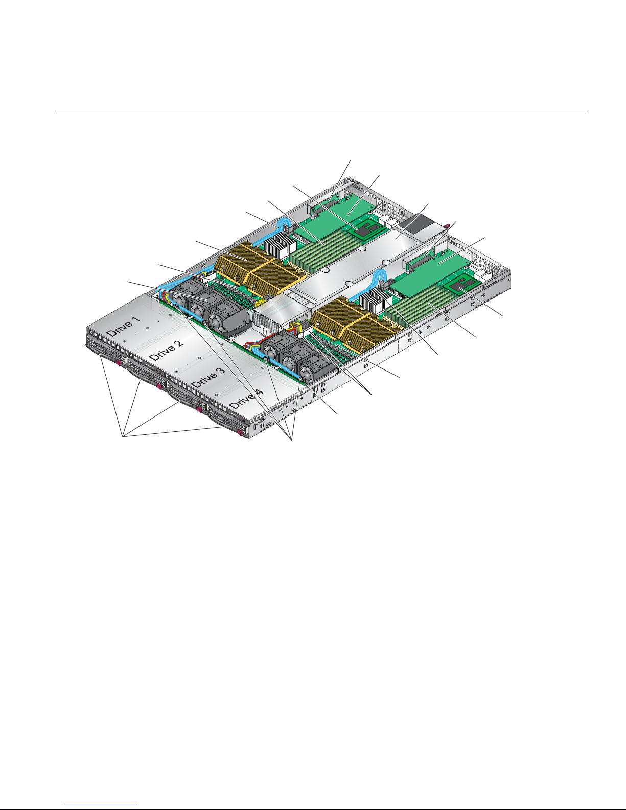
In addition to the node and chassis, the following hardware components are included (refer to
Figure 1-2):
• One or two dual-core or quad-core processors per node board
• Two processor heatsinks per node board
• Four hard drive carriers (two per node)
• One internal SATA backplane
• One SATA cable set
• Two PCI-Express 2.0 x16 riser cards (one per node)
• Two IPMI 2.0 baseboard management cards (BMCs), one per node
• Six 4-cm high-performance fans (three per node)
• Two air shrouds (one per node)
• Rackmount hardware with screws
– Two rack rail assemblies
– Six brackets for mounting the rack rails in a rack/telco rack
2 007-5466-001
Intel Xeon
processor heatsink
Node board 1
Fans
IPMI 2.0 BMC
SATA disk drive cables
DIMMs
PCIe riser card
PCIe card
Power supply
PCIe riser card
PCIe card
IPMI 2.0 BMC
DIMMs
21
SATA disk drives
2
1
SATA connections
Figure 1-2 Chassis Components
SATA disk drive cables
Node board 2
Node board 2 power connectors
SATA backplane
007-5466-001 3

1: Introduction
Node Board Features
At the heart of the SGI Altix XE320 lies two dual-processor node boards, which are based on the
Intel 5400P chipset (refer to
Note: The features on each node board are doubled for the server (refer to Appendix D, “System
Specifications”).
Processors
Each node board supports two Intel Xeon dual- or quad-core processors.
Memory
Each node board has eight 240-pin DIMM sockets (refer to Figure 1-2) that can support up to 64
GB of ECC fully buffered DIMM (FBDIMM) DDR2-800/667 SDRAM. Memory can be installed
in both interleaved (dual-channel) and non-interleaved (single-channel) configurations. All
memory modules used to populate the system should be the same size, type, and speed.
Figure 1-3). Below are the main features of the node board.
The node board memory controller supports memory mirroring to prevent data loss in case of
DIMM failure. The system maintains two copies of all the data in memory; therefore, a mirrored
system uses only half of the installed DIMMs. If a DIMM fails, the system recovers the second
copy of data from the mirrored DIMM in the opposite channel. If both the primary and the
mirrored copy of the data become corrupt, the system will fail. Configure memory mirroring with
the Memory Branch Mode BIOS setting (refer to
“Memory Branch Mode” on page 114.
Serial ATA (SATA)
The southbridge (ESB2 chip) of the 5400P chipset includes a SATA controller for 3-Gb/s SATA
drives. The hot-swappable SATA drives are connected to a backplane (refer to
provides power, bus termination, and configuration settings.
4 007-5466-001
Figure 1-2) that

Node Board Features
VGA
CONN
MT25204
VGA
ES1000
PCI-EXP x16
PCI-E SLOT
PCI-EXP x8
PCI 33MHz
PROCESSOR#2
1333/1600
MT/S
KUMERAN
Intel 5400
MCH
PCIE x4
ESB2
PROCESSOR#1
1333/1600
MT/S
FBD CHNL0
FBD CHNL1
FBD CHNL2
FBD CHNL3
PCIE x4
LPC
3.0 Gb/S
USB 2.0
FBD DIMM
SATA
USB
FBD DIMM
FBD DIMM
FBD DIMM
RJ45
RJ45
Figure 1-3 Node Board Block Diagram
007-5466-001 5
GB LAN
GILGAL
SIO
W83627
HF
MS
KB
FWH
COM2

1: Introduction
Serial Attached SCSI (SAS) and RAID Support
Appendix F, “Upgrading for SAS/SATA RAID Support,” describes how to upgrade your server
to use SAS hard drives as well as SATA hard drives by using model LSISAS3444E HBAs. This
HBA option also can provide support for RAID 0, RAID 1, or JBOD.
PCIe Expansion Slots
Each node board supports one PCI-Express 2.0 x16 slot. Two PCIe slots are available in the server
chassis.
Ethernet Ports
T wo Intel 82563EB network controllers are integrated into the 5400P chipset on each of the node
boards to support a total of four Gigabit LAN ports (100/1000
output).
Base-T/1000 BaseTX, RJ45
Onboard Controllers/Ports
Each node board I/O panel ports includes one COM port, a VGA port, two USB ports, two Gigabit
Ethernet LAN (NIC) ports, and one optional InfiniBand
®
port.
ATI Graphics Controller
The SGI Altix XE320 features an integrated ATI video controller based on the ES1000 graphics
chip. The ES1000 was designed specifically for servers, featuring low-power consumption, high
reliability, and superior longevity.
Other Features
Other onboard features that enable reliable service include voltage monitors, a chassis intrusion
header, auto-switching voltage regulators, chassis and CPU overheat sensors, virus protection,
and BIOS rescue.
6 007-5466-001

Server Chassis Features
This section describes the main features of the SGI Altix XE320 1U chassis. Refer to Chapter 5,
“Advanced Chassis Setup.” for more detailed information.
Note: For more detail on the chassis, refer to Chapter 5, “Advanced Chassis Setup.”
System Power
A single power supply (refer to Figure 1-2) provides the power for both node boards. Each node
board however, can be shut down independently of the other with the power button on its own
control panel.
Although they share a common power supply, the I2C signals used for power supply monitoring
are received by the node board 1 only. (When viewed from the front of the chassis, the node board
on the left is node board 1 and the node board on the right is the node board 2.)
Server Chassis Features
SATA/SAS Backplane/Drives
As a system, the SGI Altix XE320 supports four SA TA/SAS disk drives (refer to Figure 1-2). The
SA TA/SAS backplane is divided into two sections. A single power connector is used for the entire
backplane, but other functions, such as circuit board over-temperature monitoring, apply to both
sections. Each pair of disk drives is logically connected to its own node board. Consequently, the
RAID configuration is limited to a two-drive scheme (RAID 1 or RAID 0). The RAID
configuration cannot be set up across all four drives.
Control Panel
The chassis features two independent control panels associated with each node board in the
chassis. Each control panel has LEDs to indicate power on, network activity, hard disk drive
activity, and system overheat conditions. Each control panel also includes a main power button
and a system reset button.
007-5466-001 7

Rear I/O Panel
The I/O panel provides slots for two low-profile PCI-Express 2.0 x16 expansion cards, two COM
ports, four USB ports, two VGA ports, and four Gb Ethernet ports. The server also provides two
InfiniBand ports.
Cooling System
The server chassis has an innovative cooling design that features two sets of triple (for a total of
six) 4-cm high-performance fans. A fan speed control setting in BIOS allows fan speed to be
determined by system temperature.
System Security and Pre-Installed Linux Operating Systems
If your server was shipped with a pre-installed Linux® operating system, the password for root
was set to sgisgi for your convenience. You should change this password at your earliest
opportunity. Consult your Linux documentation for the procedure.

Chapter 2
2. Server Installation
This chapter provides a quick setup checklist to get the SGI Altix XE320 operational.
Unpack the System
Inspect the shipping container that the SGI Altix XE320 was shipped in and note if it was damaged
in any way. If the server shows damage, file a damage claim with the carrier who delivered it.
Decide on a suitable location for the rack that supports the weight, power requirements, and
environmental requirements of the SGI Altix XE320 server. It should be situated in a clean,
dust-free environment that is well ventilated. Avoid areas where heat, electrical noise, and
electromagnetic fields are generated. Place the server rack near a grounded power outlet. Refer to
“Warnings and Precautions” on page 10.
Prepare for Setup
The shipping container should include two sets of rail assemblies, two rail mounting brackets and
the mounting screws that you will use to install the system into a rack.
Read this section in its entirety before you begin the installation procedure.
Choose a Setup Location
• Leave enough clearance in front of the rack to enable you to open the front door completely,
approximately 25 in. (65 cm).
• Leave approximately 30 in. (76 cm) of clearance in the back of the rack to allow for
sufficient airflow and ease in servicing.
007-5466-001 9

2: Server Installation
Warnings and Precautions
Rack Precautions
Warning: The SGI Altix XE320 server weighs 40 lb (18 kg). Always use proper lifting
techniques when your move the server . Always get the assistance of another qualified person
when you install the sever in a location above your shoulders. Failure to do so may r esult in
serious personal injury or damage to the equipment.
Warning: Extend the leveling jacks on the bottom of the rack to the floor with the full
weight of the rack resting on them. Failure to do so can result in serious injury or death.
Warning: Attach stabilizers to the rack in single rack installations. Failure to do so can
result in serious injury or death.
W arning: Couple racks together in multiple rack installations. Failure to do so can result
in serious injury or death.
W arning: Be sure the rack is stable befor e extending a component fr om the rack. Failur e
to do so can result in serious injury or death.
Warning: Extend only one component at a time. Extending two or more components
simultaneously may cause the rack to tip over and result in serious injury or death.
10 007-5466-001

Server Precautions
• Review the electrical and general safety precautions in Appendix E, “System Safety.”
• Determine the placement of each component in the rack before you install the rails.
• Install the heaviest server components in the bottom of the rack first, and then work up.
• Use a regulating uninterruptible power supply (UPS) to protect the server from power surges
and voltage spikes and to keep your system operating in case of a power failure.
• Allow the hot plug SATA drives and power supply modules to cool before touching them.
• Always keep the rack’s front door and all panels and components on the servers closed when
not servicing to maintain proper cooling.
Rack Mounting Considerations
Ambient Operating Temperature
Rack Mounting Considerations
Reduced Airflow
Mechanical Loading
If installed in a closed or multi-unit rack assembly, the ambient operating temperature of the rack
environment may be greater than the ambient temperature of the room. Therefore, consideration
should be given to installing the equipment in an environment compatible with the manufacturer’s
maximum rated ambient temperature (
Specifications” for information.
Equipment should be mounted into a rack so that the amount of airflow required for safe operation
is not compromised.
Equipment should be mounted into a rack so that a hazardous condition does not arise due to
uneven mechanical loading.
35º C or 95º F). Refer to Appendix D, “System
007-5466-001 11

2: Server Installation
Circuit Overloading
Consideration should be given to the connection of the equipment to the power supply circuitry
and the effect that any possible overloading of circuits might have on overcurrent protection and
power supply wiring. Appropriate consideration of equipment nameplat e ratings should be used
when addressing this concern.
Reliable Ground
A reliable ground must be maintained at all times. To ensure this, the rack itself should be
grounded. Particular attention should be given to power supply connections other than the direct
connections to the branch circuit (i.e. the use of power strips, etc.).
Install the System into a Rack
This section provides information on installing the SGI Altix XE320 into a rack unit with the rack
rails provided. If the system has already been mounted into a rack, refer to
Setup” on page 21. There are a variety of rack units on the market, which may mean the assembly
procedure will differ slightly . You should also refer to the installation instructions that came with
the rack unit you are using.
“Check the Node Board
Identify the Sections of the Rack Rails
You should have received two rack rail assemblies in the rack mounting kit. Each assembly
consists of two sections: an inner fixed chassis rail that secures directly to the server chassis and
an outer fixed rack rail that secures directly to the rack itself (refer to
short brackets to be used on the front side of the outer rails are also included.
12 007-5466-001
Figure 2-1). Two pairs of

Install the Rails
I
Install the System into a Rack
Perform the following procedure to install the inner rails:
1. If the left and right side inner rails (refer to Figure 2-1) have not been pre-attached to the
chassis, attach them.
Outer rail (attaches to rack)
nner rail (pre-installed)
Locking tab
Figure 2-1 Identify Sections of the Rack Rails (right side rail shown)
2. Assemble one of the rails that attaches to the rack. (Refer to Figure 2-2.)
Figure 2-2 Rail Assembly
007-5466-001 13
2: Server Installation
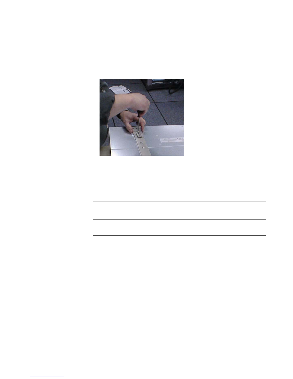
3. Install two screws to attach the inner bracket to the front of the rail. (Refer to Figure 2-3.)
Figure 2-3 Attaching the Inner Bracket
4. Attach the rail to the front of the rack chassis (refer to Figure 2-4):
a. Slide the front brackets over the appropriate holes in the rack frame.
Note: The frame of the rack fits between the two brackets on front of the rail.
b. Install the upper and lower screws to attach the rail to the rack.
Note: The middle hole remains empty. You will install a screw into this hole to secure
the server to the front of the rack.
14 007-5466-001

The sheet metal
from the rack
frame fits
between the two
brackets on the
front of the rail.
Install the System into a Rack
Attach these two screws.
Figure 2-4 Attaching the Rail to the Front of the Rack (View from Front of Rack)
5. Attach the rail to the rear of the chassis (refer to Figure 2-5):
a. Slide two clips (rail nu ts) over the appropriate holes in the rack frame.
b. Position the rail over the rack chassis (in front of the rail clips/nuts) and align to the
proper position.
c. Install two screws through the holes in the rail. The screws fasten into the two rail
clips/nuts that you previously installed.
6. Repeat Steps 1 through 5 to install the other rail in the rack.
Slide two rail
clips/nuts over
the rack frame.
Then, position
the rail and
attach it with two
screws.
The screws
fasten into the
rail clips/nuts.
Figure 2-5 Attaching the Rail to the Rear of the Rack (View from Rear of Rack)
007-5466-001 15

2: Server Installation
Locking Tabs
Both chassis rails have a locking tab (refer to Figure 2-1), which serves two functions: the first is
to lock the server into place when it is installed in the rack; the second is to lock the server in place
when it is fully extended from the rack. The locking tab prevents the server from being removed
from the rack accidentally when you pull it out for service.
Install the Server in a Rack
Warning: The SGI Altix XE320 server weighs 40 lb (18 kg). Always use proper lifting
techniques when your move the server . Always get the assistance of another qualified person
when you install the sever in a location above your shoulders. Failure to do so may r esult in
serious personal injury or damage to the equipment.
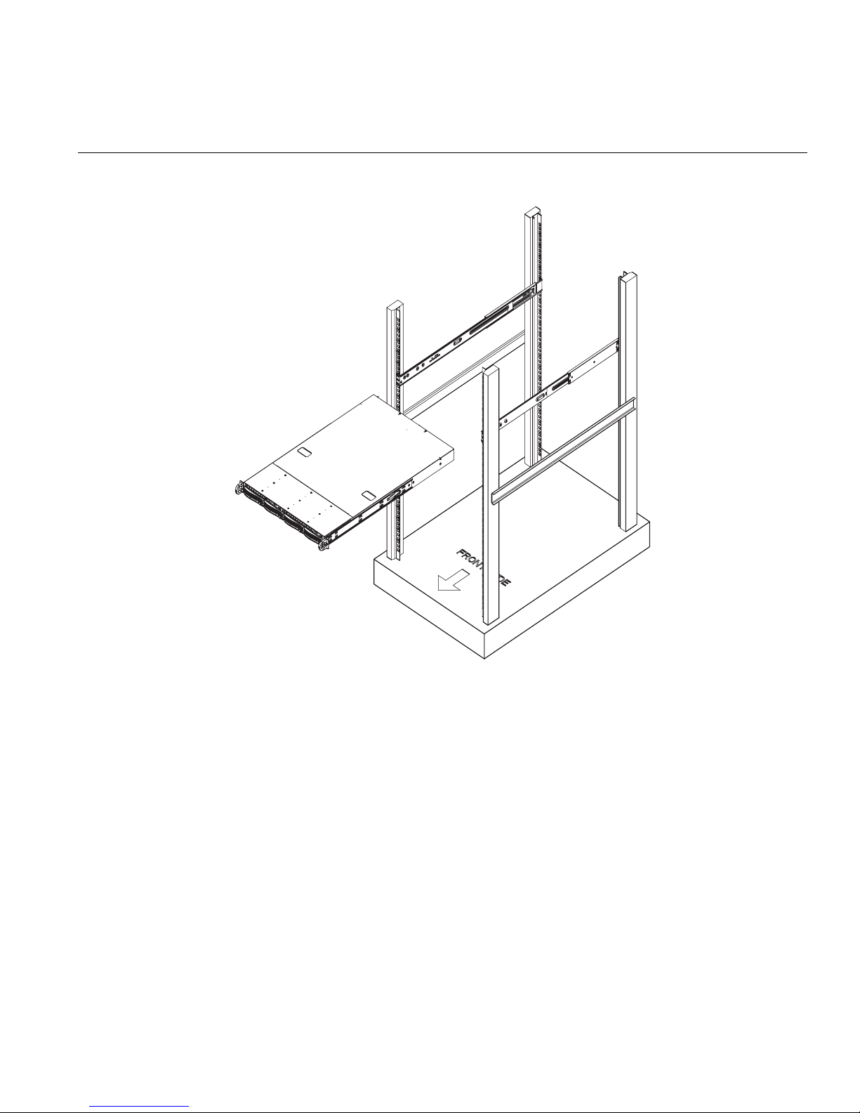
You should now have rails attached to both the server chassis and the rack unit. The next step is
to install the server into the rack (refer to
1. Line up the rear of the chassis rails with the front of the rack rails.
Figure 2-6).
2. Slide the server chassis rails into the rack rails, keeping the pressure even on both sides (you
may have to depress the locking tabs when inserting).
3. When the server has been pushed completely into the rack, you should hear the locking tabs
“click.”
4. Install and tighten two screws to secure the server to the rack.
16 007-5466-001
Install the System into a Rack
Figure 2-6 Install the Server in a Rack
007-5466-001 17
2: Server Installation
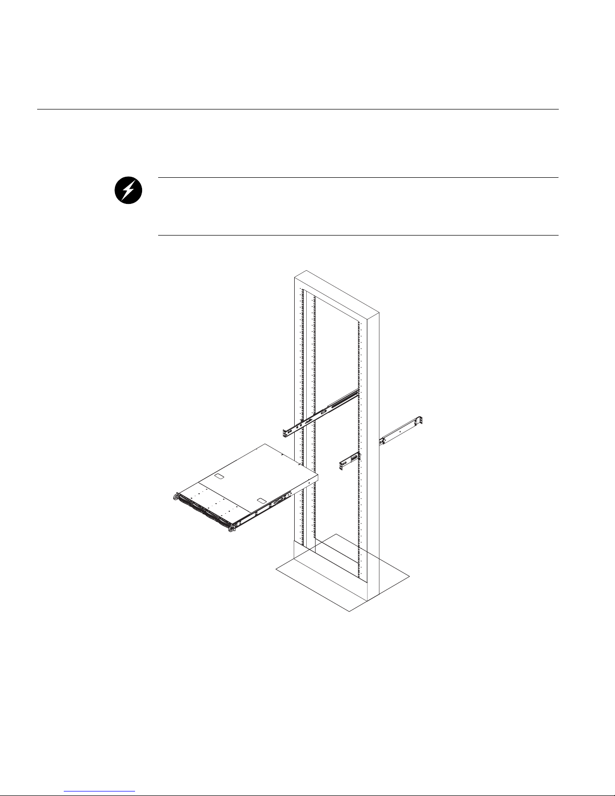
Install the Server in a Third-party Rack
Warning: The SGI Altix XE320 server weighs 40 lb (18 kg). Always use proper lifting
techniques when your move the server . Always get the assistance of another qualified person
when you install the sever in a location above your shoulders. Failure to do so may r esult in
serious personal injury or damage to the equipment.
1. Slide the server onto the outer rack rails (refer to Figure 2-7).
Figure 2-7 Install the Server in a Third-party Rack (1)
18 007-5466-001
Install the System into a Rack
2. Using three screws each, attach the outer rail assembly onto the right angle brackets.
Figure 2-8 Install the Server in a Third-party Rack (2)
007-5466-001 19

2: Server Installation
3. Install the right angle brackets onto the two-post rack, using two screws on each end.
Figure 2-9 Install the Server in a Third-party Rack (3)
20 007-5466-001

Check the Node Board Setup
Use the following sections to open the top cover and check that each node board is properly
installed and all the connections have been made.
Access the Inside of the Chassis
Refer to Figure 2-10 when using the following procedure.
1. Remove the screws that secure the system to the rack.
2. Grasp the two handles on either side and pull the system straight out until it locks (you will
hear a “click”).
3. Press the locking tabs to release the system from the rack and place it on a stable ESD-safe
work surface.
4. Remove the rack rails from the chassis so that you can gain access to the top cover screws.
5. Remove the four screws (two on the sides and two on the top) that secure the top cover to the
chassis.
Check the Node Board Setup
6. Place your thumbs in the two rectangular recesses and push the cover away from you
(toward the rear of the chassis) until it stops.
7. Lift the top cover from the chassis to gain access to the inside of the server.
Note: T o remove the system from the rack completely , depress the locking tabs in the chassis
rails (push the right-side tab down and the left-side tab up) to continue to pull the system out
past the locked position.
007-5466-001 21

2: Server Installation
2
1
2
1
Figure 2-10 Remove the Top Cover
Check the CPUs (processors)
You may have one or two processors installed on each node board. Each processor needs its own
heatsink. Refer to
Chapter 4, “Advanced Node Board Setup,” for instructions on how to install
processors and heatsinks.
Check the System Memory
Yo ur server system is shipped with system memory installed. Make sure all DIMMs are fully
seated in their slots. For details on adding system memory, refer to
22 007-5466-001
Chapter 4.

Install Expansion PCIe Cards
Y ou can install two expansion PCIe cards in the system. Refer to Chapter 4 for details on installing
PCIe expansion cards.
Check all Cable Connections and Airflow
Make sure all power and data cables are properly connected and not blocking the chassis airflow.
Refer to
Chapter 4 for details on cable connections.
Check the Drive Bay Setup
Next, you should check to make sure the SA TA/SAS drives and SA TA/SAS backplane have been
properly installed and all connections have been made.
Check the SATA/SAS Drives
Check the Node Board Setup
Depending upon your system configuration, your system may have one or more drives installed.
For detailed information about how to install SATA/SAS drives, refer to
Chassis Setup.”
Check the Airflow
Airflow is provided by six sets of 4-cm fans (each set of fans consists of two fans that are mounted
back to back). The system component layout was carefully designed to direct sufficient airflow to
cool the components that generate the most heat. Note that all power and data cables have been
routed in such a way that they do not block the airflow generated by the fans. An air shroud is also
installed to focus the airflow to areas where the most heat is generated.
Supply Power to the System
If necessary , install the system in a rack (refer to “Install the System into a Rack” on page 12), and
connect the power cord from the power supply module into a power strip or power distribution
unit (PDU). The PDU offers protection from electrical noise and power surges. SGI also
recommends that you use an uninterruptible power supply (UPS) source.
Chapter 5, “Advanced
007-5466-001 23


Chapter 3
3. Controls and Indicators
This chapter describes the functions of the controls and indicators (light emitting diodes, or LEDs)
on the SGI Altix XE320 server. There are several LEDs on the two control panels (refer to
Figure 3-1) as well as others on the drive carriers that inform you of the overall system status, as
well as the activity and status of specific components. There are also two switches (buttons) on
each control panel.
Note: The server has two control panels, one for each node board installed in the system. This
allows each node board to be controlled independently of the other.
Controls
There are two push-button switches located on each control panel: a reset switch and a power
on/off switch (refer to
• RESET: Press the reset button to reboot only the node board controlled by that control panel.
• POWER: Press power button to apply or remove power only to the node board controlled by
that control panel. Pressing this button removes the main power but keeps standby power
supplied to the node board.
Figure 3-1).
007-5466-001 25
3: Controls and Indicators
Indicators
Control panel: Node board 1
Overheat/Fan fail LED
NIC 2 activity LED
NIC 1 activity LED
Figure 3-1 Front Panel Controls and Indicators
21
Control panel: Node board 2
PowerRESET
RESET
Power LED
HDD activity LED
Each control panel is located on the front of the SGI Altix XE320 system and has five LED
indicators (refer to
Figure 3-1). Each LED provides you with critical information related to its own
specific node board.
The following items explain the node board LED indicators and the corrective action that you
should take when the LED illuminates:
• Overheat/Fan fail: When the Overheat/Fan Fail LED flashes, it indicates that a fan has
failed. When the Overheat/Fan Fail LED is on continuously, it indicates that an overheat
condition has occurred, which may be caused by cables obstructing the airflow in the system
or the ambient room temperature being too warm.
26 007-5466-001

• NIC2: Indicates network activity on LAN2 when flashing.
• NIC1: Indicates network activity on LAN1 when flashing.
• HDD: Channel activity for the hard disk drive (HDD). This light indicates drive activity on
• Power: Indicates power is being supplied to the system’s power supply unit. This LED
Drive Carrier Indicators
Indicators
Note: Check the routing of the cables and make sure all fans are present and operating
normally. Check that the chassis covers are installed properly.
Verify that the processor heatsinks are installed properly (refer to Chapter 4). Verify that the
overhead/fan fail LED remains flashing. It will remain flashing as long as the overheated or
fan fail condition exists.
the node board when flashing.
should normally be illuminated when the system is operating.
Each drive carrier has two LED indicators.
• Green
• When illuminated, the green LED on the front of the drive carrier indicates drive
activity. A connection to the SATA backplane enables this LED to blink on and off
when that particular drive is being accessed.
• Red
• The red LED indicates two states. When blinking, it indicates the drive is rebuilding.
When solid, it indicates a drive failure.
• If a drive fails, you should be notified by your system management software. Refer to
Chapter 5 for instructions about how to replace a failed disk drive.
007-5466-001 27


Chapter 4
4. Advanced Node Board Setup
This chapter includes procedures to install a node board into the SGI Altix XE320 chassis, connect
the data and power cables, and install expansion cards. All node board jumpers and connections
are also discussed.
A layout and quick reference chart is included in this chapter for your reference.
Note: Some software products are protected with software license keys derived fr om the
Access Control (MAC) ethernet address. When you replace a node board, the
Media
MAC ethernet address changes. If you are using such a product, you must request a new
license key after replacing the node board. Contact your local customer support office:
http://www.sgi.com/support/supportcenters.html
!
Caution: Install the chassis cover after you have completed accessing the components inside the
server to maintain proper airflow and cooling for the system.
Handling the Node Board
!
007-5466-001 29
Caution: Electrostatic discharge (ESD) can damage electrostatic-sensitive devices inside the SGI
Altix XE320 server. Use the ESD precautions described below when you handle printed circuit
boards or other components in the system. To prevent the node board from bending, keep one hand
under the center of the board to support it when handling it. The following measures are generally
sufficient to protect your equipment from electric static discharge.
4: Advanced Node Board Setup
ESD Precautions
Unpacking
• Use a grounded wrist strap designed to prevent electrostatic discharge.
• Touch a grounded metal object before removing any board from its antistatic bag.
• Handle each printed circuit board (PCB) by the edges; do not touch the components,
peripheral chips, memory modules, or gold contacts on the PCB.
• When handling chips or modules, avoid touching the pins.
• Place the node board, expansion PCI cards, or other boards and components into antistatic
bags when not in use.
• Make sure your computer chassis provides a conductive path between the power supply, the
case, the mounting fasteners, and the node board to chassis ground.
!
Caution: The node board is shipped in antistatic packaging to avoid electrostatic discharge
damage. Be sure to use ESD precautions when you unpack replacement components for the SGI
Altix XE320 server. Failure to do so can result in damage to the equipment.
30 007-5466-001

Node Board Installation
This section explains how to mount the node board into the SGI Altix XE320 chassis. To remove
the node board, follow this procedure in reverse order.
1. Access the inside of the system (refer to Figure 4-1):
a. Remove the rack rails so that you can gain access to the top cover screws.
b. The top cover of the chassis is secured with four screws: two at the top rear of the cover
Note: If already installed in a rack, you must first release the retention screws that secure the
unit to the rack. Then grasp the two handles on either side and pull the unit straight out until
the rails lock into place.)
Node Board Installation
and one on each side lip, also near the back. Remove all four screws, then place both
thumbs in the indentations and push the cover back until it slides off. You can then lift
the top cover from the chassis to gain full access to the inside of the server.
2
1
Figure 4-1 Remove the Top Cover
007-5466-001 31
2
1
4: Advanced Node Board Setup
2. Check compatibility of node board ports and I/O shield:
Note: Make sure that the I/O ports on the node boards align properly with their respective
holes in the I/O shield on the back of the SGI Altix XE320 chassis.
3. Remove the PCI card riser card and bracket.
4. Mount the node board onto the node board tray:
a. Carefully mount the node boards by aligning the board holes with the raised metal
standoffs that are visible in the chassis (refer to
Figure 4-2).
b. Install the six screws into the mounting holes on the node board that line up with the
5. Install the PCI riser card and bracket.
Connect the Power Cables
A node board has two 20-pin ATX power supply connectors (refer to Figure 4-2) that can be
connected to the AT X power supply. Only one of these connectors is used when the node board
is installed in the chassis. Each node board also provide a 4-pin auxiliary power connector used to
connect disk drive power to the SATA backplane.
For the node board 1 (installed on the left side of the chassis):
1. Connect the power cable to the primary ATX power header on the right side of the nod e
board.
2. Connect the auxiliary power cable to the power connector on left side of the SATA
backplane.
!
standoffs and tighten until snug. The metal screws provide an electrical contact to the
node board ground to provide a continuous ground for the system.
Caution: Do not overtighten the screws in step b. Overtightening the screws
will damage the equipment.
32 007-5466-001
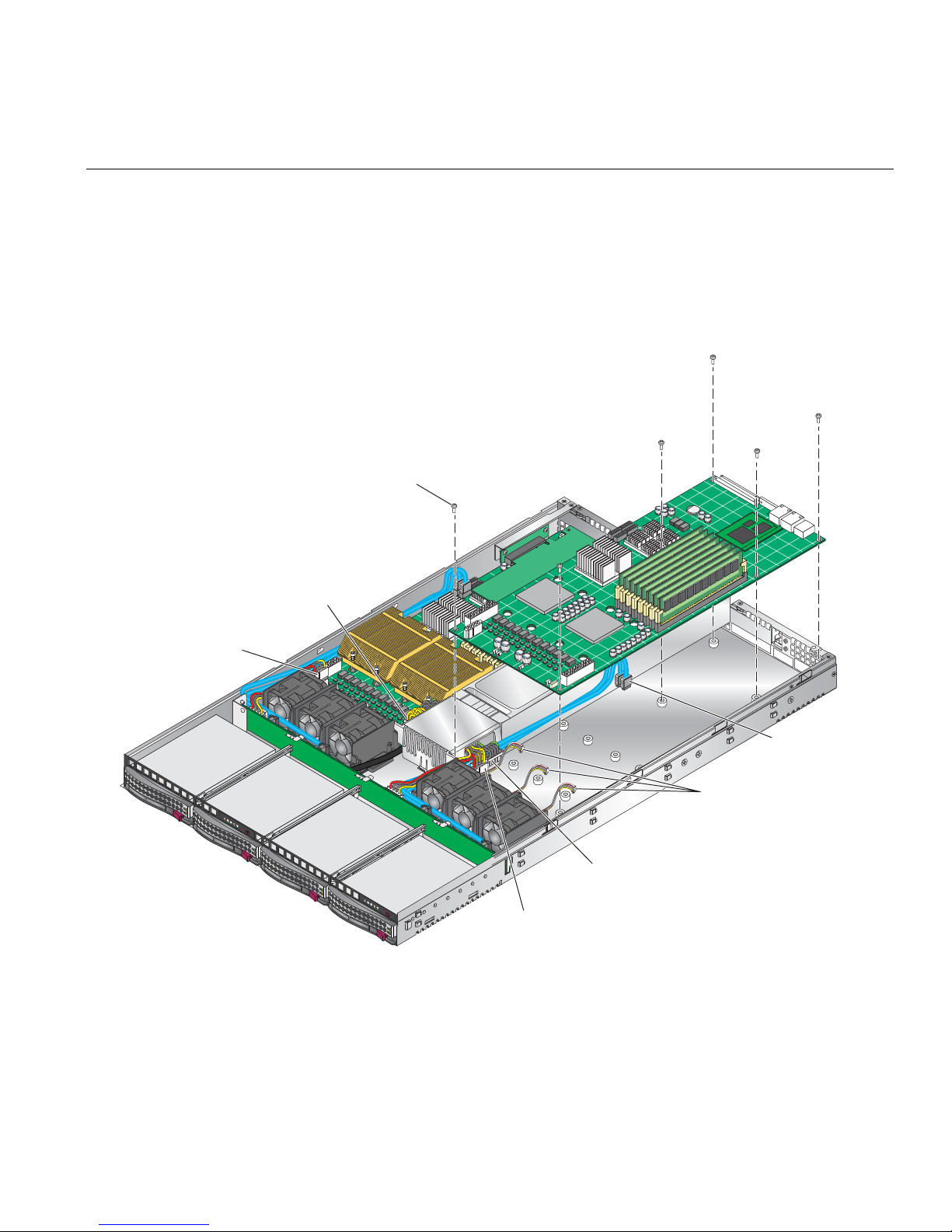
Node Board Installation
for SATA backplane
N
a
f
rs
For node board 2 (installed on the right side of the chassis):
1. Connect the power cable to the secondary ATX power header on the left side of the node
board.
2. Connect the auxiliary power cable to the power connector on right side of the SATA
backplane.
5 screws
Node board 1
power connector
ode board 1
uxiliary power connector
or SATA backplane
SATA connecto
Fan connectors
2
1
Node board 2
2
1
Node board 2
auxiliary power connector
power connector
Figure 4-2 Node Board Installation
007-5466-001 33

4: Advanced Node Board Setup
Connecting the Control Panel
The JF1 connector (refer to Figure 4-3) contains header pins for various front control panel
connectors, switches, and LED indicators.
All of the JF1 connector wires are bundled into a single ribbon cable to simplify this connection.
Make sure the red wire plugs into pin 1 as marked on the board. The other end connects to the
control panel PCB, located just behind the system status LEDs on the chassis.
20 19
Ground
x (Key)
Power On LED
IDE/SATA LED
NIC1 LED
NIC2 LED
OH/Fan Fail LED
Reserved
Ground
Ground
2 1
Figure 4-3 Control Panel Connector (JF1) Pin Definitions
NMI
x (Key)
Vcc 5V Stby
Vcc 3V
Vcc 3V Stby
Vcc 3V Stby
Vcc 3V
Reserved
Reset (Button)
Power (Button)
34 007-5466-001
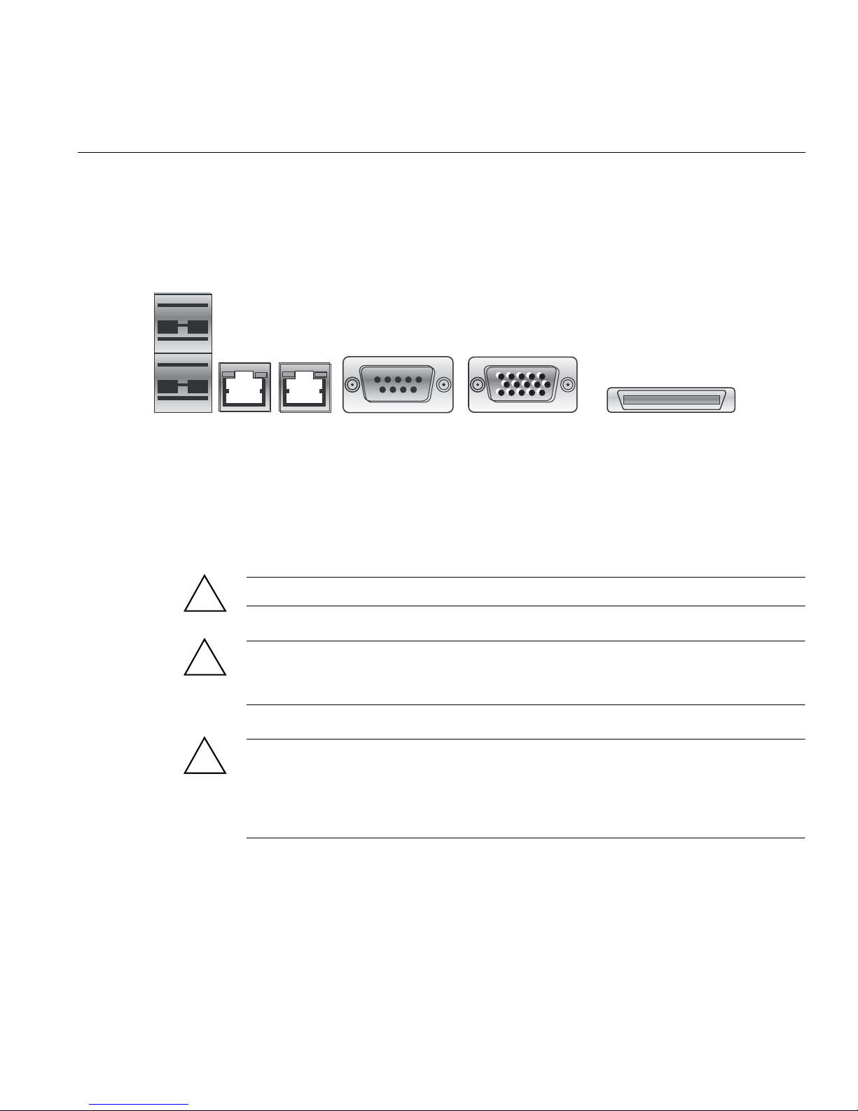
I/O Ports
U
I/O Ports
The I/O ports are color coded. Figure 4-4 shows the color and location of the various I/O ports on
the I/O panel.
SB 0/1 Ports
LAN 1 LAN 2
Figure 4-4 I/O Port Locations
COM2 Port
(Turquiose)
VGA Port
(Blue)
Processor and Heatsink Installation and Removal
!
Caution: When handling the processor, avoid placing direct pressure on the label area of the fan.
!
!
Caution: Do not place the node board on a conductive surface. A conductive surface can damage
the BIOS battery and prevent the system from booting. Always place the node board on an
ESD-safe worksurface.
Caution: Always disconnect the power before adding, removing or changing any hardware
components. Make sure that you install the processor into the CPU socket before you install the
heatsink and fan. The node board can support either one or two processors. If installing one
processor only, install it into CPU socket 2. The DIMMs run significantly cooler using socket 2
rather than socket 1.
InfiniBand Port
007-5466-001 35

4: Advanced Node Board Setup
Install a Processor
Note: SGI’s replacement Xeon CPU package contains a heatsink assembly. Make sure that the
black pick-and-place (PnP) cap is in place; otherwise, contact the SGI immediately.
Important!: When you install only a single CPU on each node board, install the single CPU in
socket 2 (refer to
Figure 4-11 on page 58) on both node boards. Install the air shroud in accordance
with “Install or Remove the Air Shroud” on page 57.
Note: A black pick-and-place (PnP) cap is attached to the load plate to protect the CPU socket.
1. Press the load lever down and away from the retention clasp to release the load plate from its
locked position.
Load Lever
PnP cap
36 007-5466-001

2. Gently lift the load lever to open the load plate.
Load plate
released
Processor and Heatsink Installation and Removal
3. Use your thumb and your index finger to hold the CPU at opposite sides.
007-5466-001 37

4: Advanced Node Board Setup
4. Align pin 1 of the CPU (the corner marked with a triangle) with the notched corner of the
CPU socket.
Caution: In step 5, do not drop the CPU on the socket. Do not move the CPU
!
horizontally or vertically, and do not rub the CPU against any surface or any of the
contacts which may damage the CPU and/or contacts.
5. Once aligned, carefully lower the CPU straight down into the socket.
6. Find the corner of the CPU that has a semi-circle cutout below a gold dot (CPU key). This
corner should be aligned with the cutout on the socket (socket key).
Gold dot
Socket keySocket key
CPU key
CPU pin 1
Notched corner
7. With the CPU in the socket, inspect the four corners of the CPU to make sure that it is
properly installed.
38 007-5466-001

Processor and Heatsink Installation and Removal
8. Use your thumb to gently push the load lever down until it snaps into the retention clasp.
Load lever
9. If the CPU is properly installed into the socket, the PnP cap is automatically released from
the load plate when the lever locks.
Caution: Retain the plastic PnP cap for shipping. The node board must be shipped with
!
the PnP cap properly installed to protect the CPU socket. Shipment without the PnP cap
properly installed may void the warranty.
007-5466-001 39

4: Advanced Node Board Setup
Install a Heatsink
10. Remove the PnP cap.
PnP cap released
from load plate
11. Repeat these steps to install a second CPU if desired.
1. Ensure that you have replaced the thermal interface material (TIM) between the heatsink and
the CPU die.
Refer to section “Replace the Thermal Interface Material” on page 42.
Caution: Use caution when you unpack the heat sink so you do not damage the TIM.
!
2. Place the heatsink on top of the CPU so that the four mounting holes are aligned with those
on the (preinstalled) heatsink retention mechanism.
Caution: Do not tighten the screws in step 3 or you may damage the CPU.
!
3. Install two screws (screw 1 and screw 2, shown in Figure 4-5) and tighten until just snug.
Caution: Do not overtighten tighten the screws in step 4 or you may damage the CPU.
!
4. Install the two remaining screws (screw 3 and screw 4, shown in Figure 4-5); then, gently
tighten all four screws.
40 007-5466-001

Screw (2)
Screw (3)
Screw (4)
Screw (1)
Figure 4-5 Install a CPU Heatsink
Processor and Heatsink Installation and Removal
Remove the Heatsink
SGI does not recommend that the CPU or the heatsink be removed from the node board. However,
if you do need to remove the heatsink, use the instructions below to prevent damage to the CPU
or the CPU socket.
1. Unscrew and remove the heatsink screws from the node board in the sequence as shown in
Figure 4-5.
Caution: Do not use excessive force when loosening the heatsink. Using excessive force
!
can damage the heatsink, CPU, or node board.
2. Grasp the heatsink and gently loosen it from the CPU.
3. When the heatsink is loose, remove it from the CPU.
4. Clean the surface of the CPU and the heatsink to remove the old thermal grease.
Refer to section “Replace the Thermal Interface Material” on page 42.
007-5466-001 41

4: Advanced Node Board Setup
5. Apply a small amount of thermal interface material (TIM) on the surface of the CPU before
you install the heatsink.
Replace the Thermal Interface Material
The Intel Xeon processors used in your server require a thermal interface material (TIM) between
the processors and heatsinks to properly dissipate the heat that is generated by the processors. If
you replace a processor and/or heatsink, you will need to remove the existing TIM from the
processor and heatsink. Then, you will need to apply new TIM to the processor before you install
the heatsink.
The TIM application instructions accompany the new TIM. The following subsections describe
how to remove the existing TIM:
• “Removing TIM from a Processor” on page 42
• “Removing TIM from a Heatsink” on page 46
Removing TIM from a Processor
You should always remove theTIM from a processor before you remove it from the node board.
Warning: Always wear gloves when performing this procedure to avoid direct skin
contact with the TIM, which is a potentially toxic material.
Tools/Parts Required:
• Dry, lint-free cloth
• Lint-free cloth moistened with isopropyl alcohol
• Gloves
Caution: T o prevent the processor from moving in its socket, ensure that the processor load lever
remains engaged while you perform the following procedure. If the processor moves while you
remove the TIM, the pins on the processor might be damaged.
42 007-5466-001
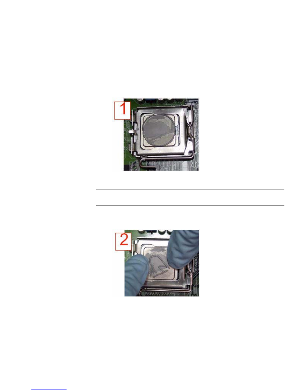
Processor and Heatsink Installation and Removal
Perform the following steps to remove the TIM from a processor:
1. Remove the heatsink from the socket.
Note: If you plan to re-use the heatsink with a replacement processor, you must clean the
TIM off of the heatsink. (Refer to “Removing TIM from a Heatsink” on page 46.)
2. Gently push any loose TIM pieces to the center of the processor.
007-5466-001 43

4: Advanced Node Board Setup
3. Use a dry lint-free cloth to lift the loose TIM pieces off of the processor.
44 007-5466-001

Processor and Heatsink Installation and Removal
4. Use a dry, lint-free cloth to wipe any remaining TIM pieces off of the processor.
5. Use a different lint-free cloth moistened with isopropyl alcohol (IPA) to remove any
remaining TIM from the processor.
007-5466-001 45

4: Advanced Node Board Setup
Note: Be sure to remove TIM from the gaps between the processor and the load plate.
Removing TIM from a Heatsink
If you plan re-use the heatsink with a replacement processor, you need to remove the TIM from
the heatsink.
Warning: Always wear gloves when performing this procedure to avoid direct skin
contact with the TIM, which is a potentially toxic material.
Tools/Parts Required:
• Dry, lint-free cloth
• Lint-free cloth moistened with isopropyl alcohol
• Gloves
Perform the following steps to remove the TIM from a heatsink:
1. Remove the heatsink from the socket and place the heatsink on a secure surface with the
bottom facing upward.
46 007-5466-001

Processor and Heatsink Installation and Removal
2. Use a dry, lint-free cloth to wipe any loose TIM pieces off of the heatsink.
007-5466-001 47
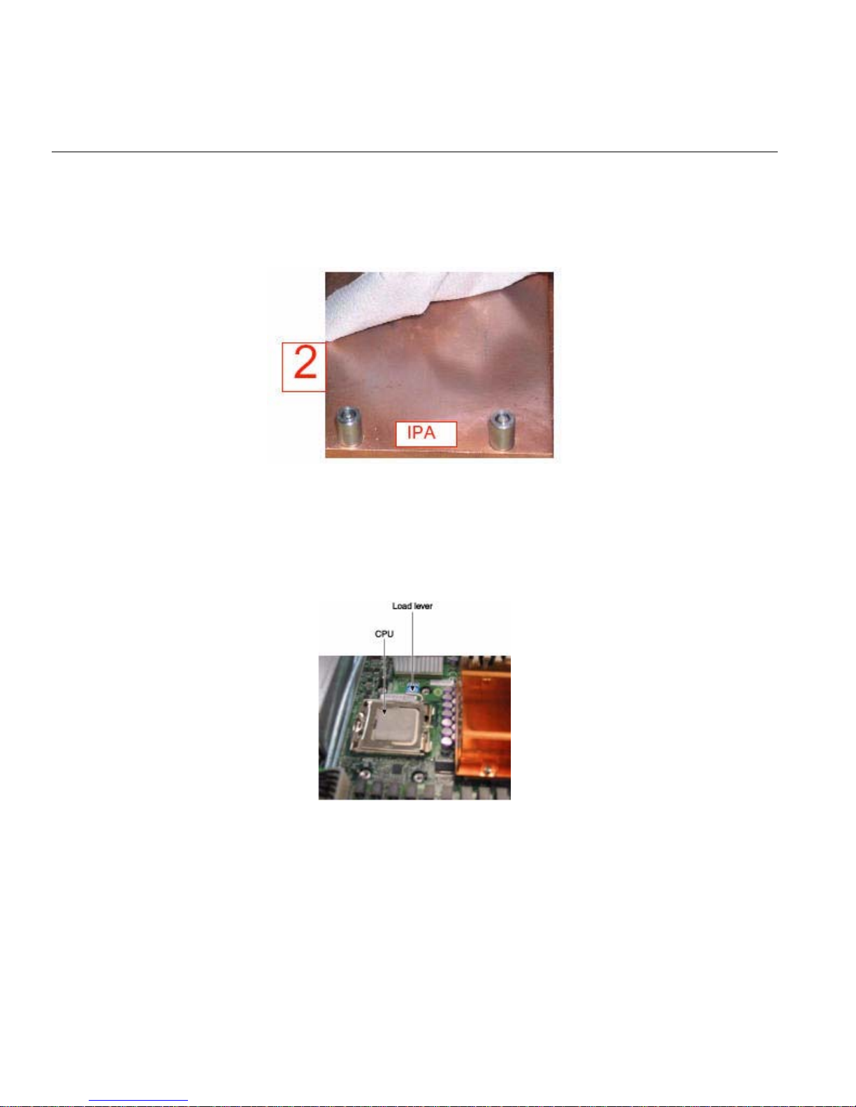
4: Advanced Node Board Setup
3. Use a different lint-free cloth moistened with isopropyl alcohol (IPA) to remove any remaining TIM
from the heatsink.
Remove the Processor
1. Press the load lever down and away from the retention clasp to release the load plate from its
locked position.
48 007-5466-001
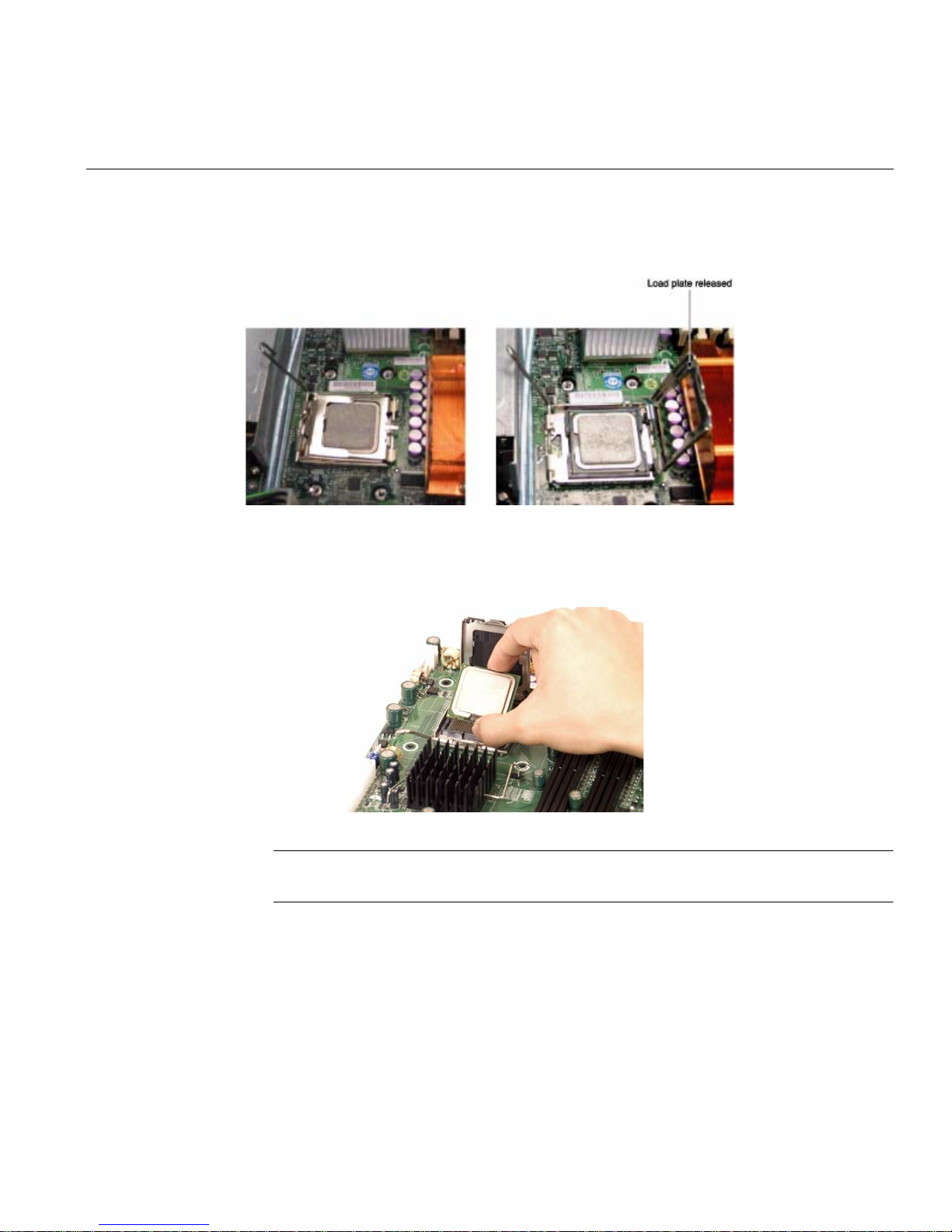
Processor and Heatsink Installation and Removal
2. Gently lift the load lever to open the load plate.
3. Use your thumb and your index finger to hold the CPU at opposite sides.
4. Carefully lift the CPU straight out of the socket.
Note: If you are removing the porcessor so that you can return the node board to SGI, install a
PnP cap in the socket.
007-5466-001 49
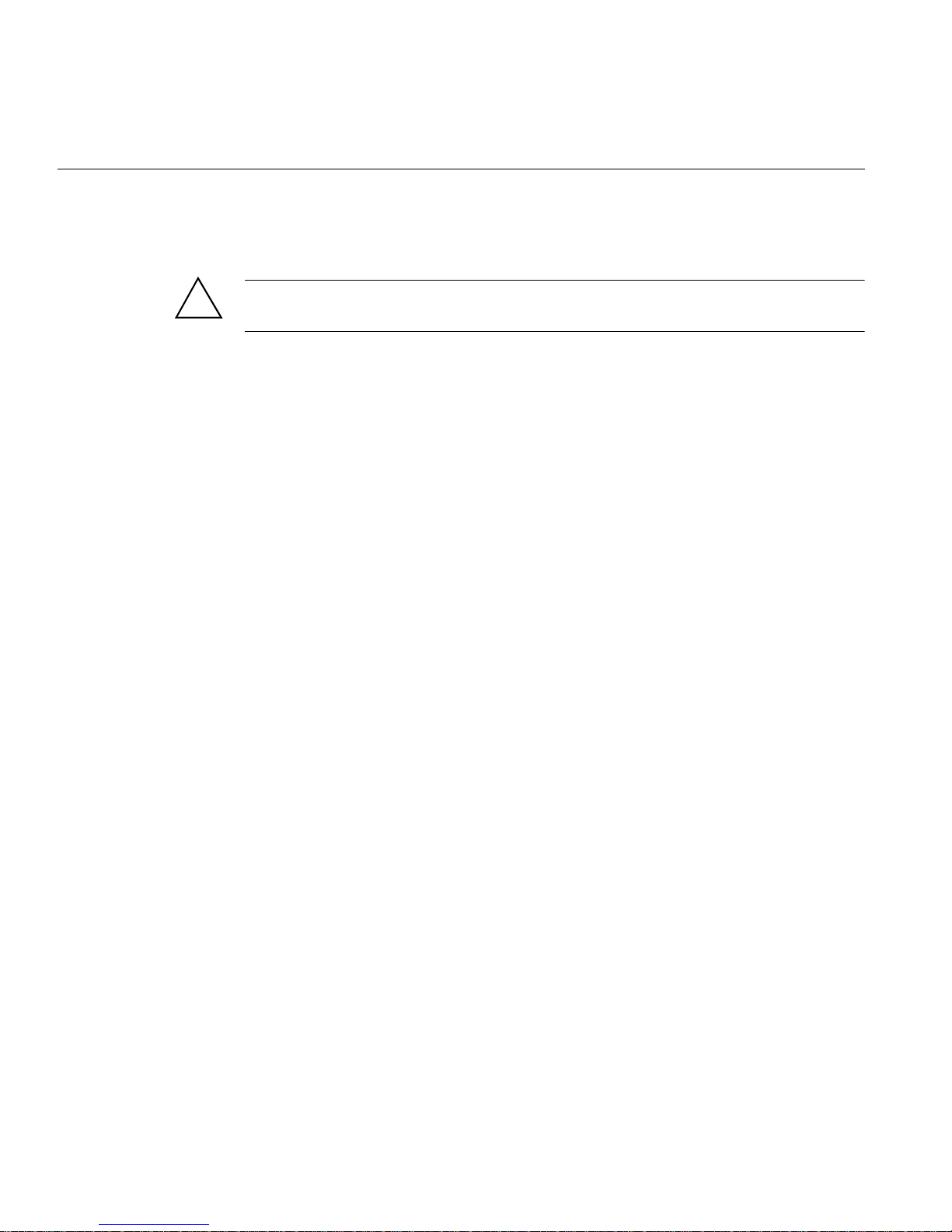
4: Advanced Node Board Setup
Install Memory
Memory Layout
!
Caution: Exercise extreme care when installing or removing DIMM modules to prevent damage
to the node board or DIMM module.
The node board provides eight 240-pin DIMM sockets that can support up to 64 GB of error
correction code (ECC) fully buffered DIMM (FBDIMM) DDR2-800/667 SDRAM (for a total of
128 GB in the system). The memory scheme is interleaved; therefore, you must always add
memory to two memory DIMM slots at a time.
installation. Figure 4-11 shows the DIMM slot designations and bank locations on the node board.
The memory controller hub (MCH) supports FBDIMM in dual-channel mode. There are a
maximum of eight DIMMs in each node board and DIMMs must be populated in groups of two
(a DIMM pair).
There are four DIMM pairs as follows:
• DIMM pair 1: 1A and 2A
• DIMM pair 2: 3A and 4A
• DIMM pair 3: 1B and 2B
• DIMM pair 4: 3B and 4B
Table 4-2 lists how to optimize your DIMM
A minimum of one DIMM pair must be installed. Figure 4-6 illustrates the minimum population
for such a configuration.
50 007-5466-001
Install Memory
DIMM 1B
DIMM 1A
Bank 1
Figure 4-6 Minimum Population for Dual-Channel Mode with Identical FBDIMMs
Constraints for DIMM Pairs
The DIMM pairs (1A,2A), (3A,4A), (1B,2B), and (3B,4B) must be identical with respect to the
following attributes:
• Size (1, 2, or 4 GB)
• Speed (667 or 800 MHz)
DIMM 2B
DIMM 2A
Bank 2
Branch 0
Memory Controller Hub (MCH)
DIMM 3B
DIMM 3A
Bank 3 Bank 4
Branch 1
DIMM 4B
DIMM 4A
• Organization (x4- or x8-bit)
The DIMM pairs (1A,1B), (2A,2B), (3A,3B), and (4A,4B) do not need to be identical with respect
to size, speed, and organization. The MCH will adjust to the lowest-speed DIMM.
007-5466-001 51

4: Advanced Node Board Setup
Performance Optimization
The primary rule for installing DIMMs to obtain maximum performance is the following:
Balance the DIMM memory capacity across both memory branches.
As illustrated in Figure 4-6, the MCH has memory Branch 0 and Branch 1. DIMMs 1A, 1B, 2A,
and 2B are on Branch 0 and DIMMs 3A, 3B, 4A, and 4B are on Branch 1. If the total memory
capacity of the DIMMs on each branch is not balanced, the memory performance will be
degraded.
Table 4-1 lists the recommended DIMM configurations to achieve maxim um performance.
Table 4-1 Recommended DIMM Configurations
DIMM Pair 1
Capacity
2GB 2GB 4GB
4GB 4GB 8GB
2GB 2GB 2GB 2GB 8GB
4GB 2GB 2GB 8GB (mixed)
4GB 4GB 2GB 2GB 12GB (mixed)
8GB 8GB 16GB
4GB 4GB 4GB 4GB 16GB
8GB 4GB 4GB 16GB (mixed)
8GB 8GB 2GB 2GB 20GB (mixed)
8GB 8GB 4GB 4GB 24GB (mixed)
8GB 8GB 8GB 8GB 32GB
DIMM Pair 2
Capacity
DIMM Pair 3
Capacity
DIMM Pair 4
Capacity
Total Node
Memory Size
Note: DIMM configurations that are not described in Table 4-1 will run with degraded
performance.
The following are examples of DIMM configurations that will yield degraded performance:
52 007-5466-001

Memory Sparing Mode
e
Install Memory
• Single DIMM pair
• Three DIMM pairs all having the same memory capacity
To select memory sparing mode, you must select sparing in the BIOS setup:
Advanced --> Advanced Chipset Control
Figure 4-7 illustrates the standard DIMM population for sparing mode.
Branch 0
Bank 1
DIMM 1A DIMM 1B DIMM 2A DIMM 2B DIMM 3A DIMM 3B DIMM 4A DIMM 4B
Figure 4-7 Standard DIMM Population for Sparing or Mirroring
Memory Mirroring Mode
The memory controller supports memory mirroring to prevent data loss in case of DIMM failure.
The system maintains two copies of all the data in memory; therefore, a mirrored system uses only
half of the installed DIMMs. If a DIMM fails, the system recovers the second copy of data from
the mirrored DIMM in the opposite channel. If both the primary and the mirrored copy of the data
becomes corrupt, the system will fail.
To select memory mirroring mode, you must select mirroring in the BIOS setup:
Bank 2
Bank 3
Branch 1
Bank 4
Mirroring
Possible
yes
yes
Sparing
Possibl
yes
yes
Advanced --> Advanced Chipset Control
007-5466-001 53

4: Advanced Node Board Setup
Configure memory mirroring with the Memory Branch Mode BIOS setting (refer to “Memory
Branch Mode” on page 114.
Figure 4-7 illustrates the standard DIMM population for mirroring mode.
The minimum number of DIMM supported in mirror mode is four. All four DIMMs must be
identical in size, speed, and organization.
Mirroring Mode Upgrade
To upgrade DIMM memory in mirroring mode, you must add four additional DIMMs. The
additional four must be identical to initial four, except for speed. The MCH will adjust to the
lowest-speed DIMM.
Install DIMMs
Align the DIMM so that the notch along the bottom of the DIMM module (refer to Figure 4-8 and
Figure 4-9) aligns with the notch in the DIMM slot. Insert DIMMs vertically and gently press
down on the DIMM until it snaps into place.
Note: Refer to “Install or Remove the Air Shroud” on page 57 for a procedure on how to remove
and install the air shrouds.
An “X” in the slot number (refer to Table 4-2) indicates that a DIMM slot is populated; “----”
indicates a DIMM slot is not populated. Both fully buffered 667 MHz and 800 MHz DIMMs are
supported, however, you need to use memory modules of the same speed and of the same type.
Interleaved memory is supported only when pairs of DIMMs are installed in both Bank 1 and
Bank
2.
54 007-5466-001

Install Memory
e
Release
Tab
Note: Align notch in
DIMM with notch in
DIMM slot
Releas
Tab
Top View of DIMM Slot
Figure 4-8 Install DIMMs
Table 4-2 lists the order in which you should install DIMMs to optimize your m emory
configuration. Figure 4-11 shows the DIMM slot designations and bank locations on the node
board.
Table 4-2 DIMM Configurations
Number of
DIMMs
2 DIMMs X ---- X ---- ---- ---- ---- ----
Bank 1 Bank 2 Bank 3 Bank 4
Slot A Slot B Slot A Slot B Slot A Slot B Slot A Slot B
4 DIMMs X ---- X ---- X ---- X ---6 DIMMs X X X X X ---- X ---8 DIMMs X X X X X X X X
007-5466-001 55
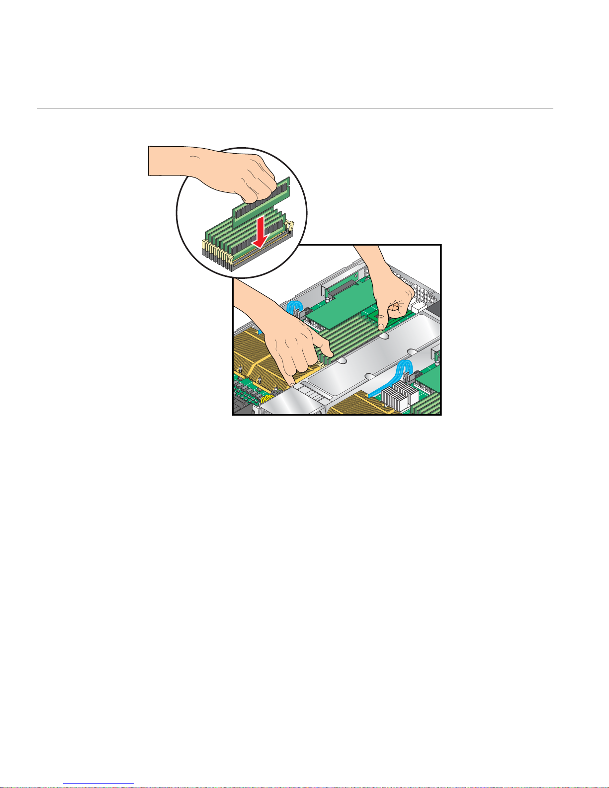
4: Advanced Node Board Setup
Figure 4-9 Replace DIMMs
56 007-5466-001
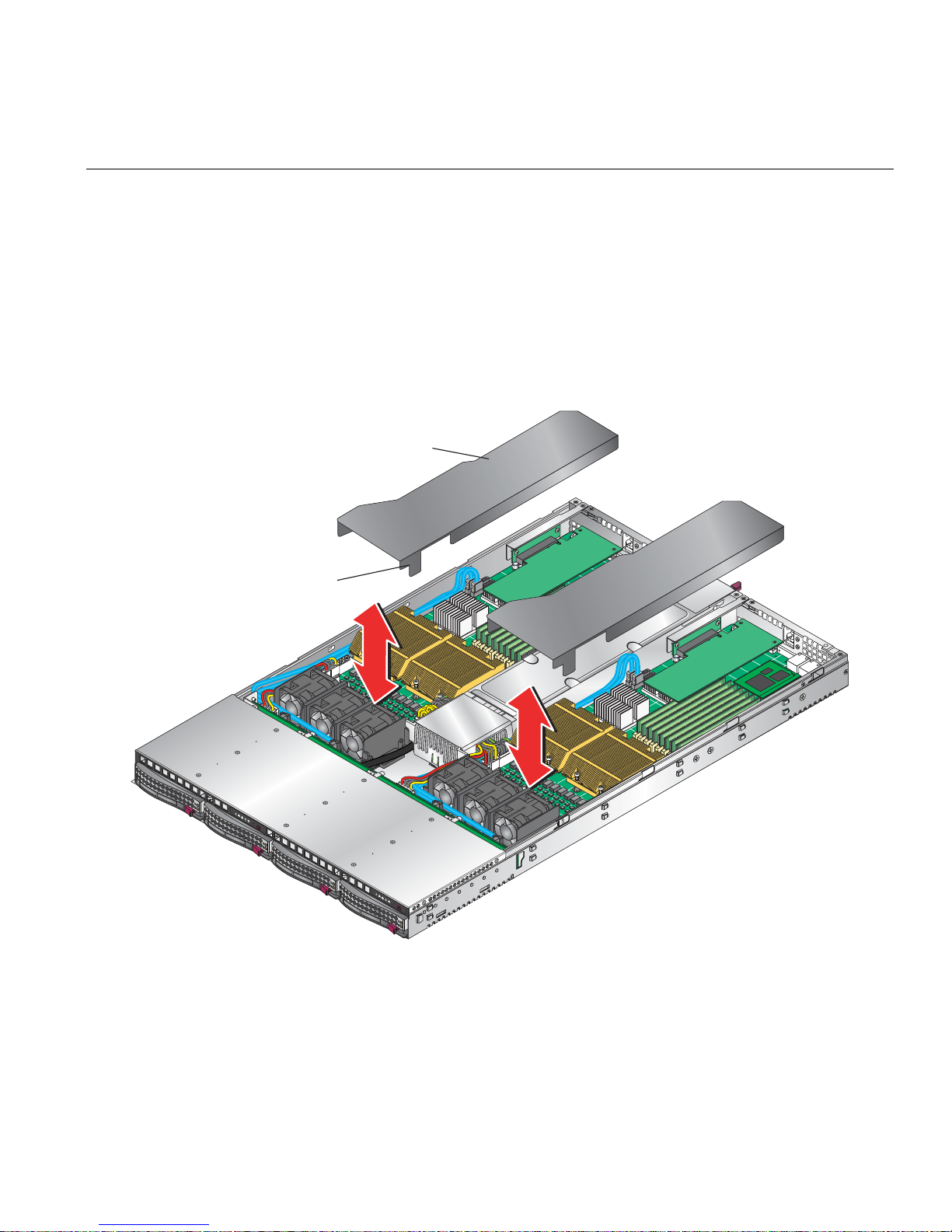
Install or Remove the Air Shroud
1. Position each air shrouds as shown in Figure 4-10.
2. Gently place the air shrouds over the node boards and just over the fan assemblies.
3. Slide the air shroud towards the rear of the chassis.
4. Position the front tab between the fan tray and 20-pin ATX power connector.
5. Press down on the front of the air shroud to secure it to the fan assemblies.
Air shroud
Front tab
Install or Remove the Air Shroud
2
1
Figure 4-10 Install Air Shrouds
007-5466-001 57
2
1

4: Advanced Node Board Setup
1
Node Board Component Locations
LAN1
DIMM 1B (bank 1)
DIMM 1A (bank 1)
DIMM 2A (bank 2)
LAN2
SIMSO
DIMM 2B (bank 2)
DIMM 3B (bank 3)
DIMM 3A (bank 3)
BIOS
DIMM 4A (bank 4)
LE3
PCI-Express x16
Speaker
JWOL
Battery
JWOR
J18
JI2C1
JI2C1
SGPIO
SATA3
SATA2 SATA0
SATA1
South Bridge
JUSB2
JL1
JOH1
LE2
JPG1
ESB2
JP1
JP7
JBT1
ATI
ES1000
JPL1
JPL2
COM2VGAInfiniBand
USB0/1
DIMM 4B (bank 4)
North Bridge
5400P
LE
JWD
JF1
CPU2 CPU1
ATX power 2
Secondary
ATX power header
JP10
Fan7/8
Fan5/6
Primary
ATX power header
Fan3/4
ATX Power 1
Fan1/2
J17
Figure 4-11 Node Board Component Locations
58 007-5466-001

Add PCIe Expansion Cards
The SGI Altix XE320 includes two preinstalled riser boards in the 1U rackmount chassis (refer to
Figure 4-12). These riser cards support two low-profile PCI Express 2.0 x16 cards.
Note: Use only SGI approved PCI Express 2.0 x16 cards in the SGI Altix XE320 server.
Install a PCIe Expansion Card
Perform the following steps to install a PCIe expansion card:
1. Remove the top cover in accordance with “Access the Inside of the Chassis” on page 21.
2. Remove the air shrouds in accordance with “Install or Remove the Air Shroud” on page 57.
3. Remove the PCIe slot EMI shield on the chassis by releasing the locking tab.
4. Insert the expansion PCIe card into the riser card and slide the bracket under the tab.
5. Secure the PCIe expansion card with the locking tab.
Add PCIe Expansion Cards
6. Install the air shrouds in accordance with “Install or Remove the Air Shroud” on page 57.
7. Install the top cover in accordance with “Access the Inside of the Chassis” on page 21.
007-5466-001 59

4: Advanced Node Board Setup
PCI riser board
Bracket
PCI expansion card
Figure 4-12 Install a PCI Card
60 007-5466-001

Node Board Jumpers and Connectors
Refer to Figure 4-11 when using Table 4-3, Table 4-4 and Table 4-5.
Table 4-3 Node Board Default Jumper Settings
Jumper Description Default Setting
JBT1 CMOS Clear Refer to “CMOS Memory Clear
JI2C1/JI2C2 I2C to PCIe Slot Open (Disabled)
JPG1 VGA Enable Pins 1-2 (Enabled)
JPL1/ JPL2 LAN1/LAN2 Enable/Disable Pins 1-2 (Enabled)
JWD Watch Dog Pins 1-2 (Reset)
Node Board Jumpers and Connectors
(JBT1)” on page 75.
IB, JIB, JWOL, JWOR, JP1, JP7,
J18, SGPIO
N/A No connection
Table 4-4 Node Board Connector Descriptions
Connector Description
ATX Power 1
ATX Power 2 20-Pin ATX PWR Connector (for Secondary Board)
COM2 COM2 Serial Port Connector
FAN 1/2 - 7/8 Chassis and CPU Fan Connectors
InfiniBand InfiniBand Connector
J17 System Management Power (I2C) Connector
J18 System Management Bus Connector
JF1 Front Control Panel Connector
JL1 Chassis Intrusion Connector (not used)
JOH1 Overheat LED Connector
JPI2C System Management Power (I2C) Connector
a
20-Pin ATX PWR Connector (for Primary Board)
007-5466-001 61

4: Advanced Node Board Setup
Table 4-4 Node Board Connector Descriptions (continued)
Connector Description
JP10 4-pin Auxiliary Power Connector (for HDDs)
JWOL Wake-on-LAN Connector
JWOR Wake-on-Ring Connector
LAN1/2 Gigabit Ethernet Ports
SATA0 – SATA3 Intel SATA 0 – 3 Ports
SGPIO Serial ATA General Purpose Input/Output Connector
SIMSO IPMI SIMSO IPMI Socket
USB0/1 USB0/1 Ports
a. The primary ATX power header is used to supply power to the node board 1 and the secondary ATX power header is
used to supply power to the node board 2. Connect the power supply to only one of these on both boards (Node board
1 is the left node board and node board 2 is the right node board when viewed from front of server).
Table 4-5 Node Board LED Descriptions
LED Indicator Description
LE1 Onboard Power LED Indicator
LE2 InfiniBand Link LED (green)
LE3 InfiniBand Activity LED (yellow)
62 007-5466-001

Node Board Connector Pin Definitions
Use Table 4-6 to locate the page number for the node board connector or jumper.
Table 4-6 Node Board Connector Pin Definitions
Connector Description Page Connector Name Page
Node Board Connector Pin Definitions
ATX Power Connector Pin Definitions
Auxiliary Power Connector Pin Definitions (JP10)
Chassis Intrusion Pin Definitions (JL1)
Fan Header Pin Definitions (Fan1/2 - Fan7/8)
HDD LED Pin Definitions (JF1)
Ethernet Ports (LAN1/LAN2)
NIC2 LED Pin Definitions (JF1)
NIC1 LED Pin Definitions
NMI Button Pin Definitions (JF1)
Overheat/Fan Fail LED Pin Definitions (JF1)
Power On LED Pin Definitions (JF1)
PW_ON Switch Pin Definitions (JF1)
Reset Switch Pin Definitions (JF1)
Serial Port Pin Definitions (COM2)
Serial General Purpose I/O Connector Pin Definitions
(SGPIO)
SMB Power Connector Pin Definitions (J17)
SMB Header Pin Definitions (J18)
Wake on LAN Connector Pin Definitions (JWOL)
Wake on Ring Connector Pin Definitions
page 64
page 64
page 68
page 68
page 66
page 70
page 66
page 66
page 67
page 65
page 67
page 65
page 65
page 71
page 71
page 72
page 72
page 70
page 70
ATX Power 1/2
COM2
Fan1/2 - Fan7/8
J17
J18
JF1
JL1
JP10
JWOL
JWOR
LAN1/LAN2
SGPIO
page 64
page 71
page 68
page 72
page 72
page 65 – page 67
page 68
page 64
page 70
page 70
page 71
page 70
007-5466-001 63
4: Advanced Node Board Setup
ATX Power Connector Pin Definitions
Table 4-7 ATX Power Connector Pin Definitions
ATX Power 20-pin Connector Pin Definitions
ATX Power 1/2
Notes Pin# Definition Pin# Definition
The main ATX power supply connectors on the node
board meet the SSI (Superset A TX) 24-pin specification .
Note: Only one of the two ATX power connectors from
each node board should be connected to the power
supply.
Auxiliary Power Connector Pin Definitions (JP10)
Table 4-8 Auxiliary Power Connector Pin Definitions (JP10)
11 PS On 1 Ground
12 5VSB 2 Ground
13 Ground 3 Ground
14 Ground 4 Ground
15 Ground 5 Ground
16 NC2 6 NC1
17 12V 7 12V
18 12V 8 12V
19 12V 9 12V
20 12V 10 12V
Auxiliary Power Pin Definitions
JP10
A 4-pin 12V auxiliary power connector is included to
provide power to hard drive disks.
64 007-5466-001
Notes Pin# Definition
1 +12V
2 Ground
3 Ground
4 +5V
PW_ON Switch Pin Definitions (JF1)
Table 4-9 PW_ON Switch Pin Definitions (JF1)
Node Board Connector Pin Definitions
PW_ON Button Pin Definitions
JF1
Notes Pin# Definition
The PW_ON connector is on pins 1 and 2 of JF1 (refer to
Figure 4-16 on page 78). This header should be connected to the
chassis power button.
Reset Switch Pin Definitions (JF1)
Table 4-10 Reset Switch Pin Definitions (JF1)
The reset connector is located on pins 3 and 4 of JF1 (refer to
Figure 4-16 on page 78) and attaches to the reset switch on the
computer chassis.
Overheat/Fan Pin Definitions (JF1)
Table 4-11 Overheat/Fan Fail LED Pin Definitions (JF1)
1 PW_ON
2 Ground
Reset Button Pin Definitions
JF1
Notes Pin# Definition
3 Reset
4 Ground
OH/Fan Fail LED Pin Definitions
JF1
The overheat (OH) fan fail LED connection is on pins 7 and 8 of
JF1(refer to
warning of chassis overheating.
007-5466-001 65
Notes Pin# Definition
7 Vcc
Figure 4-16 on page 78), which provides advanced
8 Ground

4: Advanced Node Board Setup
NIC2 LED Pin Definitions (JF1)
Table 4-12 NIC2 LED Pin Definitions (JF1)
NIC2 LED Pin Definitions
JF1
Notes Pin# Definition
The NIC2 LED connection (LAN2) is on pins 9 and 10 of JF1
(refer to
Figure 4-16 on page 78) and displays network activity on
LAN 2.
NIC1 LED Pin Definitions (JF1)
Table 4-13 NIC1 LED Pin Definitions
The NIC1 LED connection is on pins 11 and 12 of JF1 (refer to
Figure 4-16 on page 78) and displays network activity on LAN 1.
HDD LED Pin Definitions (JF1)
Table 4-14 HDD LED Pin Definitions (JF1)
9 Vcc
10 Ground
NIC2 LED Pin Definitions
JF1
Notes Pin# Definition
11 Vcc
12 Ground
HDD LED Pin Definitions
JF1
The HDD LED connection is located on pins 13 and 14 of JF1
(refer to
Figure 4-16 on page 78). Attach the hard drive LED
cable here to display disk activity (for any disk drives in the
system, including SAS, serial ATA and IDE disk drives).
66 007-5466-001
Notes Pin# Definition
13 Vcc
14 HD Active
Power On LED Pin Definitions (JF1)
Table 4-15 Power On LED Pin Definitions (JF1)
Node Board Connector Pin Definitions
Power On LED Pin Definitions
JF1
The Power On LED connector is located on pins 15 and 16 of JF1.
Use this connection is used to indicate that power is supplied to
the system.
NMI Switch Pin Definitions (JF1)
Table 4-16 NMI Button Pin Definitions (JF1)
The non-maskable interrupt button header is located on pins 19
and 20 of JF1.
Notes
Pin# Definition
15 5V Standby
16 Control
Power On LED Pin Definitions
JF1
Notes Pin# Definition
19 Vcc
20 Ground
007-5466-001 67
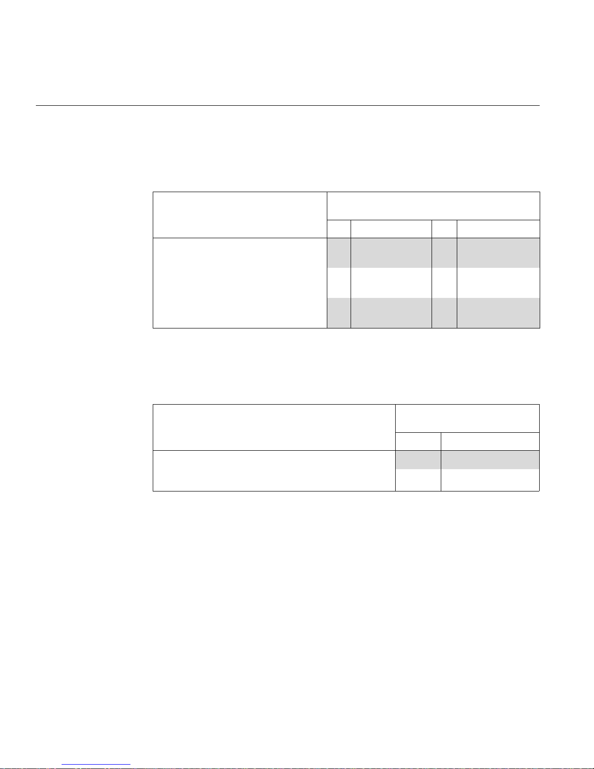
4: Advanced Node Board Setup
Fan Connector Pin Definitions (Fan1/2 - Fan7/8)
Table 4-17 Fan Header Pin Definitions (Fan1/2 - Fan7/8)
Notes Pin# Definition Pin# Definition
Fan Header Pin Definitions
Fan1/2 - Fan7/8
The node board has four 6-pin proprietary fan
headers. Each fan header supports two 3-pin
fans.
Note: The onboard fan speed is controlled by
the CPU die temperature.
Chassis Intrusion Connector Pin Definitions (JL1)
Table 4-18 Chassis Intrusion Pin Definitions (JL1)
Notes Pin# Definition
The Chassis Intrusion connector is designated JL1 (refer to
Figure 4-15 on page 77). Note: The feature is not supported on
the SGI Altix XE320 server.
1 PWR
4 Ground
(DC Speed CTRL)
2 Tachometer for Fan
1/3/5
5 Tachometer for Fan
2/4/6
3 Ground 6 PWR
(DC Speed CTRL)
Chassis Intrusion Pin Definitions
JL1
1 Intrusion Input
2 Ground
68 007-5466-001
USB Connector Pin Definitions (USB0/USB1)
Table 4-19 Universal Serial Bus (USB) Pin Definitions
Notes Pin# Definition
Node Board Connector Pin Definitions
USB Ports
USB0/1
There are two Universal Serial Bus ports located on the I/O panel and
two additional USB headers located on the node board. The headers,
labeled USB2 and USB3, can be used to provide front side USB
access (cables not included).
1 +5V
2 PO3 PO+
4 Ground
5 N/A
USB Headers
USB1, USB2
USB3/5 USB2/4
Pin# Definition Pin# Definition
1 +5V 1 +5V
2 PO- 2 PO3 PO+ 3 PO+
4 Ground 4 Ground
5 Key 5 NC
007-5466-001 69
4: Advanced Node Board Setup
Ethernet Port (LAN1/LAN2)
Table 4-20 Ethernet Ports (LAN1/LAN2)
Notes
Tw o gigabit Ethernet ports (designated LAN1 and LAN2) are located
on the I/O panel. These ports accept RJ45 type cables.
Wake on LAN Connector Pin Definitions (JWOL)
Table 4-21 Wake on LAN Connector Pin Definitions (JWOL)
Ethernet Ports
LAN1/LAN2
Wake-On-LAN Pin Definitions
JWOL
Notes Pin# Definition
The Wake-On-LAN (JWOL) connector (refer to Figure 4-14)
1 +5V Standby
enables the wake-on-LAN feature. You must enable the LAN
Wake-Up setting in BIOS and also have a LAN card with a
wake-on-LAN connector and cable installed to use this feature.
2 Ground
3 Wake-up
Wake on Ring Connector Pin Definitions (JWOR)
Table 4-22 Wake on Ring Connector Pin Definitions
Wake-On-Ring Pin Definitions
JWOR
Notes Pin# Definition
The Wake-On-Ring connector (JWOR) connector (refer to
Figure 4-14) enables the system to receive and be “awakened” by an
incoming call when in the suspend state. You must also have the
WOR card and cable installed to use this feature.
70 007-5466-001
1 Ground (Black)
2 Wake-up

Serial Port Pin Definitions (COM2)
Table 4-23 Serial Port Pin Definitions (COM2)
Node Board Connector Pin Definitions
Serial Port Pin Definitions
COM2
Notes Pin# Definition Pin# Definition
One serial port is included on the node board:
1 DCD 6 DSR
COM2 is a port located beside the VGA port.
2 RXD 7 RTS
3 TXD 8 CTS
4 DTR 9 RI
5 Ground 10 NC
Serial General Purpose I/O Connector Pin Definitions (SGPIO)
Table 4-24 Serial General Purpose I/O Connector Pin Definitions (SGPIO)
Notes Pin# Definition Pin# Definition
The Serial General Purpose Input/Output
(SGPIO) connector
(refer to Figure 4-14) is
used to communicate with the system
monitoring circuitry and monitor SATA
activity.
1 NC 2 NC
3 Ground 4 DATA Out
5 Load 6 Ground
7 Clock 8 NC
SGPIO Headers Pin Definitions
SGPIO
007-5466-001 71

4: Advanced Node Board Setup
System Management Bus Power Connector Pin Definitions (J17)
Table 4-25 SMB Power Connector Pin Definitions (J17)
Notes Pin# Definition
SMB Power (I2C) Pin Definitions
J17
The system management bus (SMB) power connector (J17) is used
to support the I2C bus.
System Management Bus Connector Pin Definitions (J18)
Table 4-26 SMB Header Pin Definitions (J18)
Notes Pin# Definition
A SMB bus connector (J18) monitors the status of the system’s
power supply, fan speed, and temperature
page 75).
(refer to Figure 4-14 on
1 Clock
2 Data
3 Power Fail
4 Ground
5 +3.3V
SMB Header Pin Definitions
J18
1 Data
2 Ground
3 Clock
4 NC
72 007-5466-001
 Loading...