

Page 1

SGI™ 1400 Server Family
Quick Start Guide
Document Number 007-3979-001
Page 2

CONTRIBUTORS
Writer Mark Schwenden
Illustrated by Dan Young and Cheri Brown
Production by Heather Hermstad and David Clarke
Engineering contributions by Jim Oliver and Courtney Carr
St. Peter’s Basilica image courtesy of ENEL SpA and InfoByte SpA. Disk Thrower
image courtesy of Xavier Berenguer, Animatica.
© 1999, Silicon Graphics, Inc.— All Rights Reserved
The contents of this document may not be copied or duplicated in any form, in whole
or in part, without the prior written permission of Silicon Graphics, Inc.
This equipment has been tested and found to comply with the limits for a Class A
digital device, pursuant to Part 15 of the FCC Rules. This equipment generates, uses,
and can radiate radio frequency energy and, if not installed and used in accordance
with the instructions, may cause harmful interference to radio communications.
LIMITED AND RESTRICTED RIGHTS LEGEND
Use, duplication, or disclosure by the Government is subject to restrictions as set
forth in the Rights in Data clause at FAR 52.227-14 and/or in similar or successor
clauses in the FAR, or in the DOD, DOE, or NASA FAR Supplements. Unpublished
rights reserved under the Copyright Laws of the United States.
Contractor/manufacturer is Silicon Graphics, Inc., 1600 Amphitheatre Pkwy.,
Mountain View, CA 94043-1351.
Silicon Graphics is a registered trademark and SGI and the Silicon Graphics logo are
trademarks of Silicon Graphics, Inc. Adobe, Acrobat,AcrobatReader, and PostScript
are trademarks of Adobe Systems Incorporated. Microsoft and Windows are
trademarks of the Microsoft Corporation. UNIX is a registered trademark in the
United States and other countries, licensed exclusively through X/Open Company,
Ltd.
SGI™ 1400 Server Family Quick Start Guide
Document Number 007-3979-001
Page 3

Contents
Introducing the SGI 1400 Family of Servers 1
Chassis Configurations 2
Site Selection and Environmental Requirements 3
Using Power Cords 5
Power Cord Requirements 6
Monitor, Keyboard, and Mouse Connectors 6
Turning On the Video Monitor and Server 8
Run the Power-On Self Test 10
Booting from a CD 11
Changing the Boot Device Priority 12
Getting Manuals from the SGI Technical Publications Library 13
Printing Manuals from the CD 13
Using the Acrobat .PDF Files 14
Using the PostScript .PS Files 15
Installing a PostScript Printer with NT 15
Installing a PostScript Printer with Linux 15
Copy Configuration Software to Diskettes 16
Product Warnings 17
iii
Page 4

Page 5
0. Introducing the SGI 1400 Family of Servers
This document is intended to help you get your new server unpacked, connected and
powered on. After completing the steps in this guide, you may wish to continue with
additional configuration, or read more about your server’s capabilities. Reference the
SGI 1400 Server Family User’s Guide for more detailed information on your system.
The SGI 1400 family of servers includes products such as the SGI 1400M (which uses a
Microsoft Windows operating system), and the SGI 1400L which uses a Linux operating
system. While its operating system (OS) gives the server a particular functional interface,
the basic hardware functions, diagnostics, and configuration are the same within the SGI
1400 server family. The generic term “server”and “SGI 1400 server”areused throughout
this document, and apply to all systems in the SGI 1400 family of servers.
Warning: To avoid personal injury when unpacking the server, use two people
and/or a mechanical assist unit to lift it off the shipping pallet. The minimum server
configuration weighs 38 kg (85 lbs); the maximum weighs 45 kg (100 lbs). Use a
hand-truck or other mechanical assist unit to move the server from one location to
another. Do not attempt to lift or move the server by the handles on the power
supplies. Before operating this server, read the additional product warnings in
“Product Warnings” on page 17.
1
Page 6

Introducing the SGI 1400 Family of Servers
Chassis Configurations
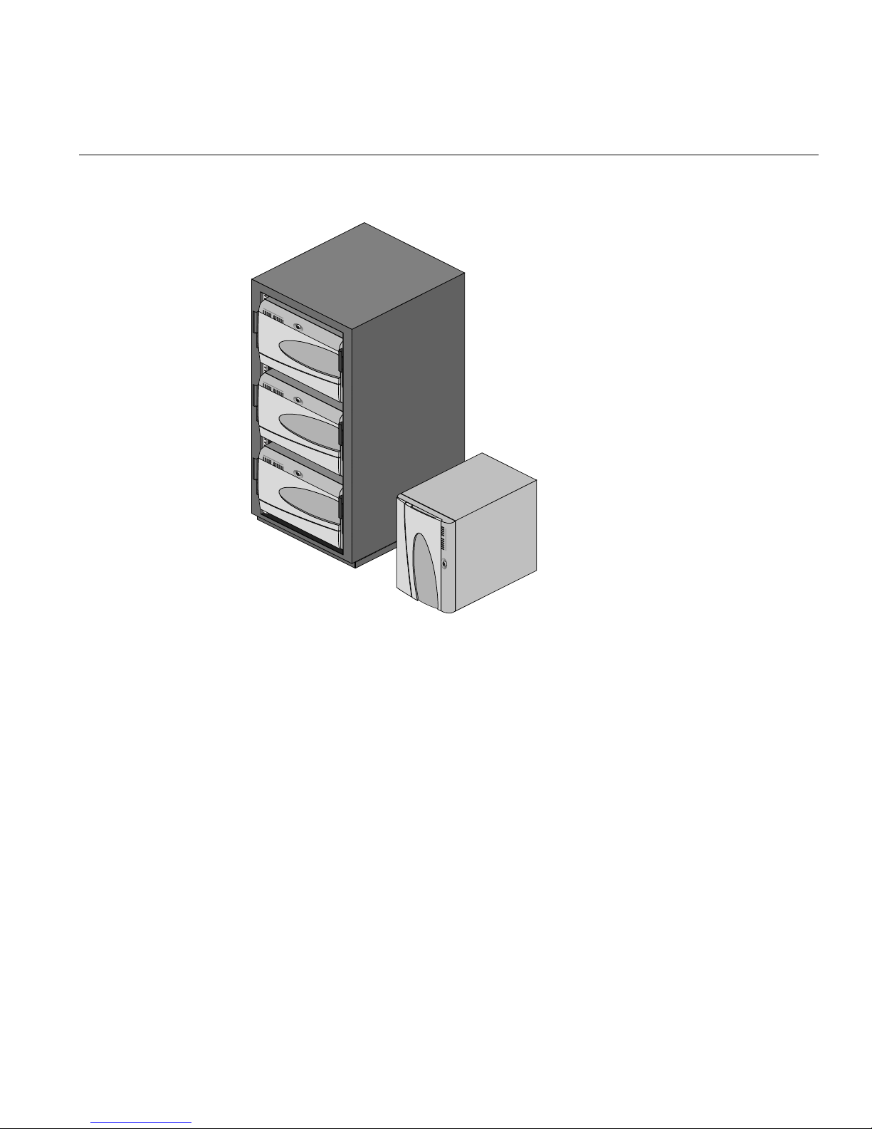
The SGI 1400 server is designed to either be mounted in a rack (rack mode) or stand
upright (pedestal mode). Figure 1 shows examples of these configurations. You must
contact your sales or service provider and purchase an adapter kit if you wish to change
the configuration of your server from one mode to another after receiving the unit.
For instructions on mounting your rack-mode serverin a 19-inch equipment rack, seethe
SGI 1400 Server Family User’s Guide.
Table 1 SGI 1400 Server Physical Specifications
Specification Pedestal Mode Rack Mode
Height 48.26 cm (19 inches) 48.26 cm (7u)
Width 31.12 cm (12.25 inches) 19-inch rack
Depth 63.5 cm (25 inches) 63.5 cm (25 inches)
Weight 38.25 kg (85 lbs) minimum
configuration
45 kg (100 lbs) maximum
configuration
Required front
clearance
Required rear
clearance
Required side
clearance
25.4 cm (10 inches) (inlet airflow
<35 ˚C / 95 ˚F)
20.3 cm (8 inches) (no airflow
restriction)
0.0 cm/inches for airflow (additional
side clearance required for service)
38.25 kg (85 lbs) minimum
45 kg (100 lbs) maximum
10 inches (inlet airflow <35 ˚C /
95 ˚F)
20.3 cm (8 inches) (no airflow
restriction)
N/A
2
Page 7
Site Selection and Environmental Requirements
Figure 1 Example Rack with Three Servers and Single Server in Pedestal Mode
Site Selection and Environmental Requirements
Use the information in this section to select a proper operational site for your server.
Caution: Electrostatic discharge (ESD) can damage disk drives, add-in boards, and
other parts. This server can withstand normallevelsof environmental ESD. However,we
recommend doing all procedures in this guide only at an ESD-protected workstation. If
one is not available, you can providesome ESD protection by wearing an antistatic wrist
strap attached to chassis ground of the server—any unpainted metal surface—when
handling components. Make sure that the power service connection is through a
properly grounded outlet.
3
Page 8
Introducing the SGI 1400 Family of Servers
Warning: The push-button on/off power switch on the front panel of the server
does not turn off the AC power.To completely remove AC power from the server, you
must unplug the AC power cord from each power supply or wall outlet.
The server operates reliably within most normal office or lab environmentallimits. Select
a site that meets the following criteria:
• Sited near a properly earthed, grounded, three-pronged power outlet
– In the United States and Canada: a NEMA 5-15R outlet for 100-120 V, or a
NEMA 6-15R outlet for 200-240 V units
– In other geographic areas: a properly earthed, grounded outlet in accordance
with the local electrical authorities and electrical code of the region
• Clean and relatively free of excess dust
• Well ventilated and away from sources of heat, with the ventilating openings on the
server kept free of obstructions
• Away from sources of vibration or physical shock
• Isolated from strong electromagnetic fields and noise caused by electrical devices
such as elevators, copy machines, air conditioners, large fans, large electric motors,
radio and TV transmitters, and high-frequency security devices
• Access space provided so the server power cords can be unplugged from the power
supply or the wall outlet; this is the only way to remove AC power from the server
• Clearance provided for cooling and airflow. For clearance requirements based on
chassis configuration, see Table 1 on page 2
4
Page 9

Table 2 provides site environmental specifications for the server.
Table 2 Site Environmental Specifications
Temperature
Using Power Cords
Nonoperating
Operating
Humidity
Nonoperating
Operating wet bulb
Shock
Operating
Packaged
Acoustic noise < 55 dBA with three power supplies at 28 ˚C +/- 2 ˚C
Electrostatic discharge
(ESD)
AC Input Power
100-120 V∼
200-240 V∼
–40˚ to 70 ˚C (–55˚ to 150 ˚F)
10˚ to 35 ˚C (41˚ to 95 ˚F); derated 0.5 ˚C for every 1000 ft (305 m)
Altitude to 10,000 ft (3,050 m) max; maximum rate of change = 10 ˚C per
hour
95% relative humidity (noncondensing) at 30 ˚C (86 ˚F)
Not to exceed 33 ˚C (91.4 ˚F) (with diskette drive or hard disk drive)
2.0 g, 11 msec, 1/2 sine
Operational after 30-inch (76.2 cm) free fall (cosmetic damage might
occur)
Tested to 20 kilovolts (kV) per environmental test specifications; no
component damage
100-120 V∼, 7.6 A, 50/60 Hz
200-240 V∼, 3.8 A, 50/60 Hz
Using Power Cords
This section supplies information on the proper use of power cords with your server.
Caution: Do not modify or use a supplied AC power cord if it is not the exact type
required in the region where the server will be installed and used. Replace the cord with
the correct type. Read the information in “Power Cord Requirements”.
Do not plug in any of the server’s power cords when internal parts are being added
(boards, DIMMs, removable media drives). See the SGI 1400 Server Family Maintenance
and Upgrades Guide for more information on this topic.
5
Page 10

Introducing the SGI 1400 Family of Servers
Power Cord Requirements
The server’s power cords must meet these requirements:
• Rating: Cords must be rated for available AC voltage and have a current rating at
least 125% of current rating of server.
• Connector, wall outlet end: Cords must be terminated in grounding-type male
plug designed for use in your region. It must have certification marks showing
certification by an agency acceptable in your region.
• Connector, power supply end: The connector that plugs into the AC receptacle on
the server power supply must be an IEC 320, sheet C13, type female connector.
• Cord length and flexibility: Cords must be less than 4.5 meters (14.76 feet) long,
and must be flexible (harmonized <HAR>) cord or VDE-certified cordage to
comply with server's safety certifications.
Note: In geographic regions that are susceptible to electrical storms, use of a surge
suppressor is highly recommended.
For information about complying with electromagnetic interference regulations, see
“Electromagnetic Compatibility” in the SGI 1400 Server Family User’s Guide.
Monitor, Keyboard, and Mouse Connectors
This section provides information on connecting your server’s monitor, keyboard, and
mouse. Your server may come with a PCI Ethernet card, be sure to read the board’s
documentation for information on its operation and functionality.
Caution: Before connecting any external devices, make sure the server is not plugged
in, or equipment could be damaged.
6
Page 11
Monitor, Keyboard, and Mouse Connectors
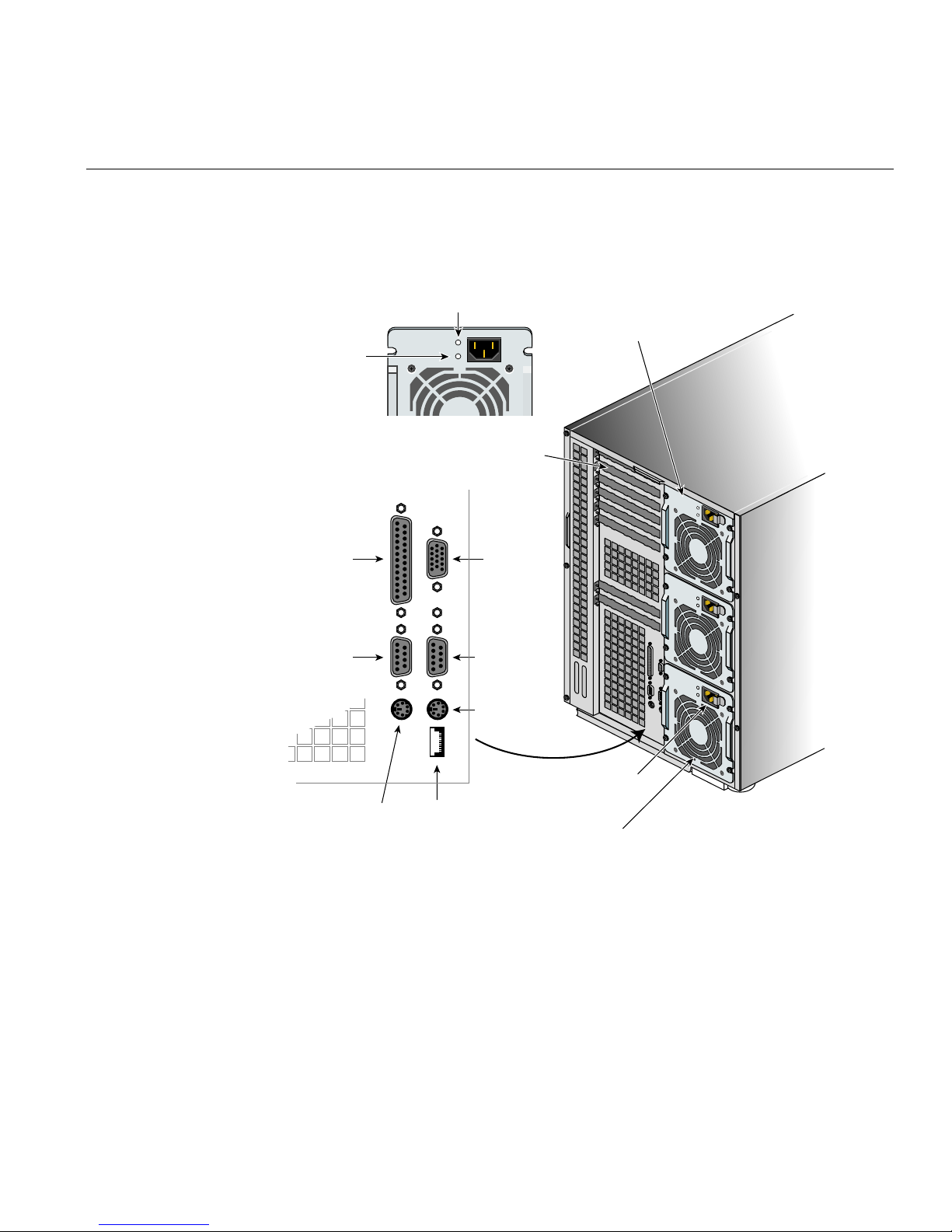
Figure 2 shows the monitor, keyboard, mouse, and other connector locations on the back
of the server.
Power supply failure LED
Power supply
Power
supply
LED
Expansion slot
Parallel port
Serial port A,
COM1
Mouse
connector
USB port
VGA
monitor
connector
Serial port B,
COM2
Keyboard
connector
AC input power
connector
Power supply fan
Figure 2 SGI 1400 Server Rear Connectors and Controls
7
Page 12

Introducing the SGI 1400 Family of Servers
Turning On the Video Monitor and Server
Follow these steps before turning on the server and any optional video monitor:
1. Make sure all external devices, such as a monitor, keyboard, and mouse, have been
connected.
2. Remove drive protection card (if present) from the diskette drive.
3. Turn on the video monitor (if installed).
4. Plug the female end of each server AC power cord into each power supply input
receptacle on the back of the chassis.
5. Plug the male end of each server AC power cord into a wall outlet (a grounded,
three-pronged AC power outlet; see “Using Power Cords” on page 5).
6. If the server does not come on when you plug it into the AC outlet, press the
push-button on/off power switch on the front panel.
7. Verify that the power-on light on the front panel is lit. After a few seconds, the
power-on self test (POST) begins.
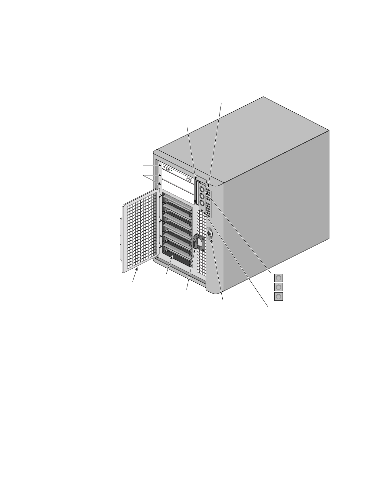
Note that there are 11 LED status indicators on the upper-right section of the server’s
front. Starting from the top down, they indicate the following functions:
• system power on
• disk bay power on
• hard disk activity
• system fan failure
• power supply failure
• the bottom six LEDs indicate individual hard drive 0 through 5 activity
8
Page 13
CD-ROM drive
Expansion
drive bays
Turning On the Video Monitor and Server
Front panel LEDs
Diskette drive
Internal
EMI shield
drive bays
EMI shield
lock
System
security lock
Figure 3 SGI 1400 Server Front Controls and Indicators
Power On/Off button
Sleep/service button
Reset button
NMI button
9
Page 14

Introducing the SGI 1400 Family of Servers
Run the Power-On Self Test
Each time you turn on the system, a power-on self test (POST) starts running. POST
checks the baseboard, processors, memory, keyboard, and most installed peripheral
devices. During the memory test, POST displays the amount of memory it is able to
access and test. The length of time needed to test memory depends on the amount of
memory installed. POST is stored in flash memory. Follow these steps:
1. Turn on your video monitor and system. After a few seconds, POST begins to run.
2. After the memory test, these screen prompts and messages appear:
Keyboard Detected
Mouse Initialized
Press <F2> to enter Setup
3. If you do not press F2 and do not have a device with an operating system (OS)
loaded, the above message remains for a few seconds while the boot process
continues, and the system beeps once. Then this message appears:
Operating System not found
If you do not press F2, the boot process continues and this message appears:
Press Ctrl C to enter SCSI Utility
4. Press Ctrl+C if SCSI devices are installed. When the utility opens, follow the
displayed instructions to configure the onboard SCSI host adapter settings and to
run the SCSI utilities. Also see “Using the Symbios SCSI Utility” in the SGI 1400
Server Family User’s Guide. If you do not enter the SCSI utility, the boot process
continues.
5. Press Esc during POST to access a boot menu when POST finishes. From this menu,
you can choose the boot device or enter BIOS Setup.
After POST completes, the system beeps once.
What appears on the screen after this depends partly on which OS is loaded on your
system.
10
Page 15
Booting from a CD
Booting from a CD
Under certain circumstances you may need to load (or reload) the operating system from
a CD.
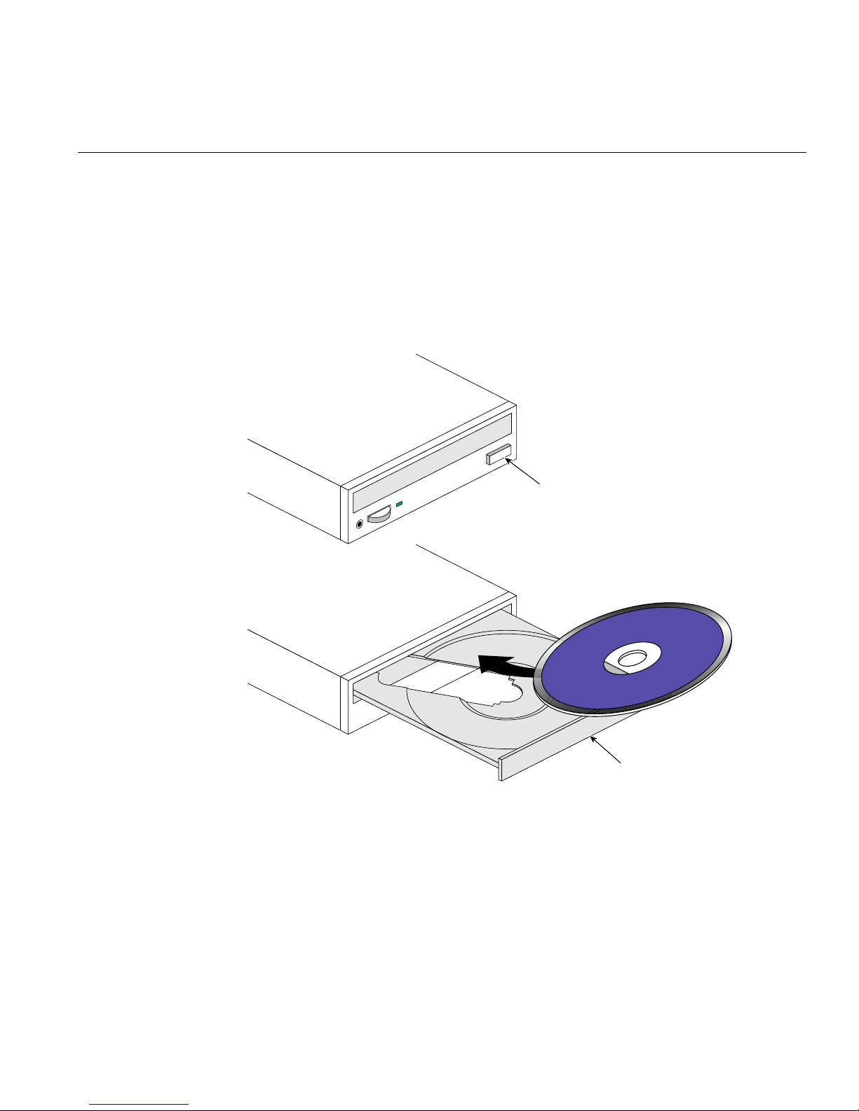
Note: Handle the CD by its inner and outeredges. Do not touchthe side without thelabel
(the data side). See Figure 4 for an example.
Open/close
push-button switch
Figure 4 Typical Loading Procedure for a CD-ROM Drive
CD tray, CD with label side up
11
Page 16

Introducing the SGI 1400 Family of Servers
The SGI 1400 server you receive from Silicon Graphics contains a fully functional OS
installed on the hard disk when shipped from the factory. You should only need to
reinstall the OS if you experience a major disk or filesystem failure.
Note: If the server’s prompt shows you a display indicating “Operating System Not
Found.” Follow the steps in “Changing the Boot Device Priority” on page 12 as this may
indicate that someone has changed the boot device priority.
1. Open the CD tray by pressing the open/close button on the front panel of the
CD-ROM drive. The tray will slide out of the drive.
2. Open the CD case. Press down on the center hub of the case to release the CD.
3. Gently grasp the center hole and outer edge of the CD. Remove it from the case, and
place it label-side up in the CD tray.
4. Press the open/close button or gently push on the CD tray—it will automatically
slide into the drive.
5. Push the reset switch on the front panel to restart the server.
6. When POST completes, the server boots from the CD, installs a mouse driver, and
displays the CD-ROM menu bar. Use the arrow keys to scroll through the menu bar
and to view the tasks in the pop-up menus.
Changing the Boot Device Priority
You have two choices for changing boot device priority. The easier option (listed first,
below) is good for only one boot; the longer option takes effect until you change boot
device priority again.
1. At any time during POST, press Esc. When POST completes, a pop-up Boot menu
appears.
2. Use the arrow keys to highlight Removable Media, then press Enter.
or
Boot the server. The CD can be in the drive or not.
3. The BIOS name and version will display. Immediately below, you’ll see the size of
memory detected in the server.
12
Page 17

Getting Manuals from the SGI Technical Publications Library
4. Quickly press the F2 key (a prompt to do this may or may not appear). After a few
biotope tests complete, the main BIOS Setup screen appears.
5. From the Setup screen, select Boot Menu. Press Enter.
6. Select Boot Device Priority, and press Enter.
7. In the Boot Device Priority screen, use the up- or down-arrow keys to select the
desired boot device, then press the + key to move it to the top of the list.
8. The other two boot option devices become the second boot device and the third boot
device.
9. Press the F10 key to save your changes and exit Setup.
10. When the Exit prompt appears, press Enter again.
11. The bootup process continues. When finished, an OS prompt displays.
12. Make sure the primary boot device is properly installed (along with removable
media as appropriate), and boot the server.
Getting Manuals from the SGI Technical Publications Library
If you would like to access manuals on the SGI 1400 server using the World Wide Web,
SGI makes its manuals available in a variety of formats via the Web. Using your Web
browser, open the following URL:
http://techpubs.sgi.com/library
Enter a keyword search, or search by title to find the information or manual you need.
Printing Manuals from the CD
In addition to the hard copy manuals you received with your server, SGI provides soft
copy manuals on the CD in the following viewable and printable formats:
• PDF files: read and print .PDF files using an Adobe Acrobat Reader. Note that the
reader is not pre-installed with every operating system shipped.
• PS (PostScript) files: print .PS files directly to a PostScript printer.
13
Page 18

Introducing the SGI 1400 Family of Servers
Because printing from within Acrobat can be time-consuming, we recommend printing
only a small range of pages for immediate use. If you want to print all the manuals on
the CD, we recommend printing them from the .PS files (see “Using the PostScript .PS
Files” on page 15).
Using the Acrobat .PDF Files
Before you can print manuals from your server using Acrobat, you must connect a
printer to the parallel port.
1. From the CD-ROM menu bar, select Read/Print Manuals and press Enter. The
Adobe Acrobat reader will be automatically installed on RAM disk d: (simulated
disk drive in RAM memory) and automatically started. The reader lets you view
and print out manuals.
2. After the reader starts, a pop-up menu displays a list of manuals. If you are not sure
which manual applies to your server, check the title page of this Quick Start Guide
for the correct product reference.
3. The menu may also include a manual for SCSI devices in the server.
4. Use your mouse or the up- and down-arrow keys to select the manual. Double click
the left mouse button or press Enter to load the .PDF file for the manual.
5. Use your mouse or the Tab key to select the .PDF file for the manual. Double click
the left mouse button or press an arrow key and Enter to view the .PDF file.
6. Follow the program options and prompts. If you need to access the Help menu,
double click on Help or press Alt+h.
14
Page 19

Printing Manuals from the CD
Using the PostScript .PS Files
Before you can print manuals from the CD in your server, you must connect a printer to
the parallel port. Then use the supplied PostScript files (.PS) to print a hard copy of a
manual or other information you may want.
Installing a PostScript Printer with NT
User’s with an NT operating system should use the following guidelines:
1. From the CD-ROM menu bar, select Quit to DOS and press Enter.
2. From the pop-up menu, select Quit Now and press Enter.
3. At the prompt C:\>, type dir c:\manuals and press Enter.
4. At the prompt, type dir c:\(manual name)\pscript and press Enter to see a list
of .PS files.
5. Use the copy or print command to send the .PS files directly to a PostScript printer
using the appropriate driver.
6. At the prompt C:\>, type menu and press Enter to return to the CD-ROM menu.
Installing a PostScript Printer with Linux
If the server uses the Linux operating system, use these guidelines to install and
configure the printer:
1. Attach a printer to the parallel port.
2. As root, run /usr/sbin/printtool
This launches a graphical user interface (GUI) you can use to edit the server’s
/etc/printcap file and create a spool directory for your printer.
Note: Alternately, you can edit the /etc/printcap file on your system directly to
enable the printer you have connected. The text file
/usr/doc/HOWTO/Printing-HOWTO provides information on configuring a printer
using /etc/printcap.
3. Click on the Add button in the RHS Linux Print System Manager GUI.
4. Choose local printer; note that you can also set up remote printers here as well, such
as a UNIX-type lpd queue or lanmanager printer using SMB.
5. When Linux detects the port that your printer is on, click OK.
15
Page 20

Introducing the SGI 1400 Family of Servers
6. You are dropped into a menu to edit the printer entry information: (name of printer,
spool directory, filelimit in Kb 0=nolimit, printer device).
7. Click on the input filter Select button and this allows you to choose your printer
type. It should provide a description of the driver as well, so that if you do not see
your printer you may find a compatible driver.
8. When you see your printer on the list, select it and click OK.
9. Click OK in the edit local Printer Entry dialog box.
10. In the RHS Linux Print System Manager click on lpd > restart lpd.
11. Undertests, click on print ascii test page. If the test page does not eject at the end, go
back and highlight your printer name, then click edit > input filter select and toggle
on the Send EOF after job to eject the page, click OK and try again.
12. Next, send a test print PostScript file to test the printer function.
Copy Configuration Software to Diskettes
When you copy software from the CD onto diskettes, device drivers suitable for several
different OSs are copied onto the diskettes. However, your OS will read only those
drivers it can recognize,so you cannot usually check the directory of a diskette that is not
formatted for your OS. Instead, you might see a message to the effect, disk not
formatted, do you want to format it now?
In most cases, the drivers for YOUR OS
are on the diskette and available to load on the system.
1. Before starting, make sure that you have several blank high-density diskettes.
2. From the CD-ROM menu bar, select Create Diskettes and press Enter.
3. Follow the prompts to copy the software onto the diskettes.
4. When finished, from the CD-ROM menu bar, select Quit to DOS and press Enter.
5. Remove the CD from the CD-ROM drive.
16
Page 21

Product Warnings
Product Warnings
Caution: The power supplies in this product contain no user-serviceable parts. Refer
servicing only to qualified personnel. Do not attempt to modify or use a supplied AC
power cord if it is not the exact type required. The server has a separate AC power cord
for each supply. The DC push-button on/off switch on the system does not turn off
system AC power. To remove AC power from the system, you must unplug each AC
power cord from the wall outlet or power supply.
Whenever you remove the chassis covers to access the inside of the system, follow these
steps:
1. Turn off all peripheral devices connected to the system.
2. Turn off the system by using the push-button on/off power switch on the system.
3. Unplug all AC power cords from the system or from wall outlets.
4. Label and disconnect all cables connected to I/O connectors or ports on the back of
the system.
5. Provide some electrostatic discharge (ESD) protection by wearing an antistatic wrist
strap attached to chassis ground of the system—any unpainted metal surface—
when handling components.
6. Do not operate the system with the chassis covers removed.
After you have completed the six SAFETY steps above, you can remove the system
covers. To do this:
1. Unlock and remove the padlock from the back of the system if a padlock has been
installed.
2. Remove and save all screws from the covers.
3. Remove the covers.
17
Page 22

Introducing the SGI 1400 Family of Servers
For proper cooling and airflow, always reinstall the chassis covers before turning on the
system. Operating the system without the covers in place can damage system parts. To
install the covers:
1. Check first to make sure you have not left loose tools or parts inside the system.
2. Check that cables, add-in boards, and other components are properly installed.
3. Attach the covers to the chassis with the screws removed earlier, and tighten them
firmly.
4. Insert and lock the padlock to the system to prevent unauthorized access inside the
system.
5. Connect all external cables and the AC power cord(s) to the system.
Caution: A microprocessor and heat sink may be hot if the system has been running.
Also, there may be sharp pins and edges on some board and chassis parts. Contact
should be made with care. Consider wearing protective gloves. There is a danger of
explosion if the battery is incorrectly replaced. Replace only with the same or equivalent
type recommended by the equipment manufacturer.Discardused batteries according to
manufacturer’s instructions.
18
The system is designed to operate in a typical office or lab environment. Choose a site
that is:
• Clean and free of airborne particles (other than normal room dust).
• Well ventilated and away from sources of heat including direct sunlight.
• Away from sources of vibration or physical shock.
• Isolated from strong electromagnetic fields produced by electrical devices.
• In regions that are susceptible to electrical storms, we recommend you plug your
system into a surge suppressor and disconnect telecommunication lines to your
modem during an electrical storm.
• Provided with a properly grounded wall outlet.
• Provided with sufficient space to access the power supply cords, because they serve
as the product’s main power disconnect.
 Loading...