

Silicon Energy SiE2900, SiE3840, SiE4900, SiE5300 Owner's Manual

Owner’s Manual
Silicon Energy Solar Inverter
SiE2900 / SiE3840
SiE4900 / SiE5300

ZOMG-8253USYUS0

1
© 2011 SILICON ENERGY All rights reserved SiEV2.3

2

3

4
Safety
SAVE THESE INSTRUCTIONS– This manual contains important instructions for
the Silicon Energy Solar Inverter Models SiE5300, SiE4900, SiE3840 & SiE2900
that shall be followed during installation and maintenance of the Silicon Energy
Solar Inverter [hereafter SiE Inverter(s)].
Safety Precautions/Safety Notes
Only trained qualified electrical personnel are to perform the electrical installation,
wiring, opening and repair of the SiE Inverters. Even when no external voltage is
present, the SiE Inverters can still contain high voltages and the risk of electrical
shock.
The temperature of the heat sinks outside of the device can reach over 70°C (158°F)
in normal operation (Ambient temperature rating: 55°C / 131°F). There is the risk
of burn injury when these parts are touched.
The following general safety precautions must be observed during all phases of
operation, service, installation and repair of this device. Failure to comply with
these precautions or with specific warnings elsewhere in this manual violates safety
standards of design, manufacture, and intended use of the device. The manufacturer
assumes no liability for the customer’s failure to comply with these requirements.
5
Safety Symbols
To reduce the risk of injury and to ensure the continued safe operation of this
product, the following safety instructions and warnings are marked in this manual.
Warning, ris k of electric shock
Presents safety information to prevent injury or death to users and/or
installers.
Earth ground symbol
!
Caution (refer to accompanying documents)
Presents information to prevent damage to this product.

6
General Safety Precautions
Personnel must remove all conductive jewelry or personal equipment prior
to installation or service of the device, parts, connectors, and/or wiring.
Trained qualified personnel are required to mount, reconfigure or repair this
device.
Licensed electricians are required to install permanently wired equipment.
Stand on an insulated surface when working on the operating device (i.e.,
ensure that there is no grounding).
Instructions in this manual must be precisely followed and all information
on cautions or warnings must be adhered to.
Use proper lifting techniques whenever handling enclosure, equipment or
parts.
The SiE Inverter must be provided with an equipment-grounding conductor
connected according to local codes and regulations.
The SiE Inverter must be provided with a DC grounding connection
according to NEC and Local Electrical codes. The grounded conductor must
be ungrounded and energized when a ground fault is indicated.
The AC Neutral connection is only for voltage sensing and shall be neither
used to carry currents nor bonded to ground inside the inverter.
These precautions/warnings do not contain all measures pertinent to the safe
operation of the device. If special problems arise which are not described in
sufficient detail for the purposes of the buyer, contact your specialized
dealer or technician.

7
Safe Installation and Operation
Installation of the device must be in accordance with the safety regulations
(e.g., UL1741) and all other relevant national or local regulations. Correct
grounding and short circuit protection must be provided to ensure
operational safety.
Read all instructions and cautionary remarks in the manual before
installation.
Switch off the circuit breakers before installation and wirings. Avoid
standing water when working on the inverter.
PV arrays will be energized when exposed to light. Cover the arrays with
opaque (dark) material during installation and wiring.
Check both of the AC and DC connections with a digital volt meter prior to
any installation or removal procedures.
Attach the outer cover correctly before switching on the circuit breakers.
Install the inverter out of direct sunlight.
When no external voltage is present; the SiE Inverter can still contain high
voltages and the risk of electrical shock.
Allow at least 5 minutes for the inverter to discharge completely after
disconnecting the AC and DC sources from the inverter.
External heat sinks can reach high enough temperatures in normal operation
to cause skin burn injury when these parts are touched. Pay attention to high
temperature components.
To prevent the risk of fire hazard, do not cover or obstruct the heat sink.
Allow changes in your electrical system to be carried out only by qualified
electricians.
8
Repair and Maintenance
The SiE Inverter contains no user serviceable parts, except for the fan, the
PV string fuses and the GFDI fuse. Only SILICON ENERGY trained staff is
authorized to carry out internal repair and maintenance of the unit. Please
return the device for repair and maintenance for faults caused by parts other
than the fan and the fuses described above. For maintenance and
replacement of the fuses, please refer to the section 5.4.
WARNING!
DO NOT make alterations or tamper with the assembly in the
inverter without manufacturer’s authorization unless specified
elsewhere in this Manual. This may result in injury, electric
shock, or fire and void the warranty.
Wiring the inverter
Input/Output Terminals: Use wire size #10 AWG to #6, 90°C (194°F)
Copper Wire.
Reconfirm that all connections have been performed properly and all
screws are properly tightened.
WARNING!
All electrical installatio n and the wiring methods shall be done
in accordance with the local and National Electrical codes
ANSI/NFPA 70 and should follow the important safety
instructions in this manual.
WARNING!
Make sure that you use suit able connecting cables for both the
AC and DC wiring. The cable must be adequately dimensioned
and suitably inert to temperature fluctuation, UV radiation
and other possible hazar ds.
9
!
Connection of the AC cable
WARNING!
Reconfirm that the circuit breaker to the main utility is
switched OFF before connecting the power cable from the
breaker to the AC connector.
Connection of the DC cable
CAUTION!
Identify the different polarity of DC voltage on each PV string
and connect respectively to the input terminals marked
“UNGROUNDED CONDUCTOR” and “GROUNDED
CONDUCTOR”. Make sure the DC voltage that PV arrays
generate is equal or less than 6 00 VDC in any case.
WARNING!
Route the DC connection cables to the SiE Inverters away from
any possible hazar ds t hat could damage the cables.
WARNING!
Hazardous voltage is still present on the device after
disconnection of all PV DC inputs. Allow 5 minutes for the
inverter to discharge the energy completely.
WARNING!
PV arrays will be energized when exposed to light. Cover the
arrays with opaque (dark) materials during installation and
wiring.

10
Contents
1. INTRODUCTION 15
1.1 GENERAL 15
1.2 SPECIFICATIONS 17
1.3 ACCESSORIES 23
2. INSTALLATION 24
2.1 PLACEMENT 24
2.2 MOUNTING 25
2.3 WIRING THE INVERTER 31
2.3.1 Connection of the AC cable ............................................................ 38
2.3.2 Connection of the DC cable............................................................ 40
2.3.2.1 Connection of the DC wires for Negative Ground Arrays .............. 43
2.3.2.2 Connection of the DC wires for Positive Ground Arrays ............... 45
2.3.2.3 Connection of the DC wires for Negative Ground Arrays without
Internal DC Fuses ......................................................................................... 47
2.3.2.4 Connection of the DC wires for Positive Ground Arrays without
Internal DC Fuses ......................................................................................... 50
2.3.3 Connection of the Communication cable ........................................ 53
2.4 WIRING INVERTER IN PARALLEL 56
3. OPERATION 58
3.1 OVERVIEW 58
3.2 OPERATION FE AT UR E 60
3.3 LED INDICATION 62
3.4 LCD DI S PLAY 64
3.5 COMMUNICATION 80
3.6 EXPLANATIONS OF ERROR MESSAGES 80

11
4.
WARRANTY INFORMATION 84
5. TECHNICAL DOCUMENTATION 88
5.1 OUTLINE DRAW IN G 88
5.2 EFFICIENCY 90
5.3 DE-RAT IN G OPERATION 94
5.4 MAINTENANCE 97
5.4.1 Exchange of the GFDI Fuse ........................................................... 97
5.4.2 Exchange of the PV String Fuses .................................................... 98
5.4.3 Factory Service ............................................................................. 100
5.4.3.1 Remove the Inverter ...................................................................... 101
5.4.3.2 Re-install the Inverter ................................................................... 108
6. WEATHER PROOF SHIELD (OPTIONAL) 115

12
List of Figures
Fig1.1.1 Grid Connected Solar System Overview ............................................. 16
Fig 2.1.1 Clearances required for SiE Inverter installation ............................... 25
Fig 2.2.1 Remove the bracket from the inverter.................................................. 26
Fig 2.2.2 Inverter mounting br ack et ................................................................... 27
Fig 2.2.3 Fasten the mounting bracket ............................................................... 28
Fig 2.2.4 Fasten the Inverter on the mounting bracket ...................................... 31
Fig 2.3.1 Turn the DC/AC disconnect switch OFF ............................................. 32
Fig 2.3.2 Loosen the screws ................................................................................ 33
Fig 2.3.3 Remove the cover of the wiring box .................................................... 33
Fig 2.3.4 Remove the covers for the cable through holes ................................... 34
Fig 2.3.5 Wiring box front view .......................................................................... 35
Fig 2.3.6 Utility configuration jumpers .............................................................. 37
Fig 2.3.7 Utility configuratio ns .......................................................................... 38
Fig 2.3.1.1 AC Terminal Block for AC cable connections................................. 39
Fig 2.3.2.1 SiE2900 s u ppor t s onl y t hree (3) PV string fuses .................................. 41
Fig 2.3.2.2 PV- terminal connection ................................................................. 42
Fig 2.3.2.1.1 Negative Ground Setting and DC wires connections ................. 44
Fig 2.3.2.1.2 DC terminal blocks for DC cable connection in Negative
Ground .................................................................................................... 44
Fig 2.3.2.2.1 Positive Ground Setting and DC wire connections .................... 46
Fig 2.3.2.2.2 DC terminal blocks for DC cable connection in Positive
Ground .................................................................................................... 46
Fig 2.3.2.3.1 Negative Ground Setting and DC wires connections array
without internal DC fuses ........................................................................................ 48
Fig 2.3.2.3.2 DC terminal blocks for DC cable connection in Negative
Ground array without internal DC Fuses ............................................................... 49

13
Fig 2.3.2.4.1
Positive Ground Setting and DC wires connections
array without internal DC fuses .............................................................................. 51
Fig 2.3.2.4.2 DC terminal blocks for DC cable connection in Positive
Ground array without internal DC Fuses ............................................................... 52
Fig 2.3.3.1 Positions of the communication ports and termination switch ....... 54
Fig 2.3.3.2 RJ-45 Pins and Signals ................................................................... 54
Fig 2.3.3.3 RS-232 connection .......................................................................... 55
Fig 2.3.3.4 RS-485 connection .......................................................................... 56
Fig 2.4.1 Parallel configu ra tion of inverter ....................................................... 57
Fig 3.3.1 Front panel of the SiE Inverter ............................................................ 62
Fig 3.4.1 SiE Inverter LCD display lay-out ........................................................ 79
Fig 5.1.1 Outline Drawing of SiE2900/3840 ...................................................... 88
Fig 5.1.2 Outline Drawing of SiE4900/5300 ...................................................... 89
Fig 5.2.1 CEC Efficiency of the SiE2900 = 96.0% (240V) ................................. 90
Fig 5.2.2 CEC Efficiency of the SiE2900 = 95.5% (208V) ................................. 90
Fig 5.2.3 CEC Efficiency of the SiE3840 = 96.0% (240V) ................................. 91
Fig 5.2.4 CEC Efficiency of the SiE3840 = 95.5% (208V) ................................. 91
Fig 5.2.5 CEC Efficiency of the SiE4900 = 96.0% (240V) ................................. 92
Fig 5.2.6 CEC Efficiency of the SiE4900 = 96.0% (208V) ................................. 92
Fig 5.2.7 CEC Efficiency of the SiE5300 = 96.0% (240V) ................................. 93
Fig 5.2.8 CEC Efficiency of the SiE5300 = 95.5% (208V) ................................. 93
Fig 5.3.1 Temperature derating curve of the SiE2900 ........................................ 95
Fig 5.3.2 Temperature derating curve of the SiE3840 ........................................ 96
Fig 5.3.3 Temperature derating curve of the SiE4900 ........................................ 96
Fig 5.3.4 Temperature derating curve of the SiE5300 ........................................ 97
Fig 5.4.1.1 Open the cap of the GFDI fuse holder ............................................ 98
Fig 5.4.2.1 Replacement of the PV string fuses ................................................ 99
Fig 5.4.3.1.1 Remove the cover of the Inverter ............................................. 102

14
Fig 5.4.3.1.2
Remove the DC and AC wires .................................................. 103
Fig 5.4.3.1.3 Keep the well-wrapped DC and AC wires stored in the wiring
box ......................................................................................................................... 103
Fig 5.4.3.1.4 Remove the screws and nuts bonding between the inverter and
wiring box .................................................................................................. 104
Fig 5.4.3.1.5 Un-hang the inverter carefully ................................................. 105
Fig 5.4.3.1.6 Locate the cover plate in place and fasten the screws ............. 107
Fig 5.4.3.2.1 Re-install the cover plate and fix it on the top of the wiring
box .................................................................................................. 109
Fig 5.4.3.2.2 Hang the inverter onto the mounting bracket carefully ........... 110
Fig 5.4.3.2.3 Fasten the screws and nuts bonding between the inverter and
the wiring box for its construction and grounding continuity ............................... 111
Fig 5.4.3.2.4 Connect the AC wirings to their correct terminals indiv idually .... 111
Fig 5.4.3.2.5 Fasten the screws of cover of the inverter firs, then the wiring
box .................................................................................................. 112
Fig 6.1 Step 1: Release the screw of the inverter cover ................................. 115
Fig 6.2 Step 2: Put the shield on the sides of the inverter. ............................. 116
Fig 6.3 Step 3: Fasten the shields with the screws. ........................................ 116
Fig 6.4 An inverter with the weather proof shield. ........................................ 117

15
1. Introduction
1.1 General
We appreciate your choice of Silicon Energy Solar Inverters for your power
conversion devices in your solar power system. This document contains the
information you need for the installation and settings of the SiE Inverters.
Therefore, it is strongly recommended to read this manual carefully before the
SiE Inverter installation and settings.
The Silicon Energy Solar Inverter [hereafter SiE Inverter(s)] product family is
a series of grid-connected photovoltaic inverters which are designed to convert
DC power generated by photovoltaic arrays to AC power that is delivered to the
home loads and then fed into the utility grid with any excess power. The
SiE2900, SiE3840, SiE4900, and SiE5300 are the members of the family for the
North American market. The overview of the grid-tied solar energy system is
shown in figure 1.1.1. SiE Inverters utilize state-of-the-art technology, reliability
and ease of use and comply with the requirements of UL1741 Standard for
Inverters, Converters, Controllers and Interconnection System Equipment for
Use With Distributed Energy Resources. SiE Inverters also comply with the
IEEE 1547 Standard for Interconnecting Distributed Resources with the Electric
Power Systems; and IEEE 1547.1 Standard Conformance Test Procedures for
Equipment Interconnecting Distributed Resources with Electric Power Systems;
and FCC Part 15 Subpart B EMI/EMC Emissions Regulations for a Class B
device.
The SiE Inverter is designed to operate automatically once it is installed and
commissioned correctly. When the DC input voltage generated by the
photovoltaic array rises above the pre-set threshold value, the embedded
16
controller starts and goes through a system check mode and then into monitoring
mode until the PV Start Voltage is reached. During this time, the SiE Inverter
will not generate AC po wer. Once all conditions necessary for grid connection
are satisfied, the SiE Inverter goes into the Grid/MPPT mode and begins feeding
the AC power into the grid. When the input DC voltage falls below the
minimum MPP voltage setting, the SiE Inverter will then shut itself down. The
SiE Inverter will be awakened automatically should the input DC voltage rise
above the pre-set threshold value.
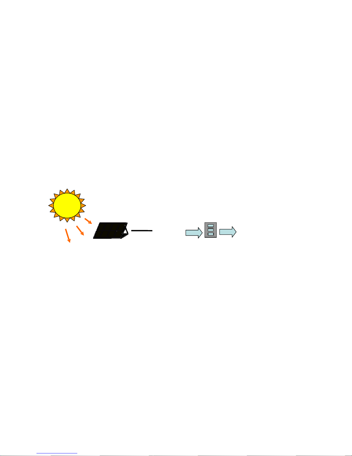
Fig1.1.1 Grid Connected Solar System Overview
Photovoltaic Array
Utility Grid
Meter
SiE Inverter

17
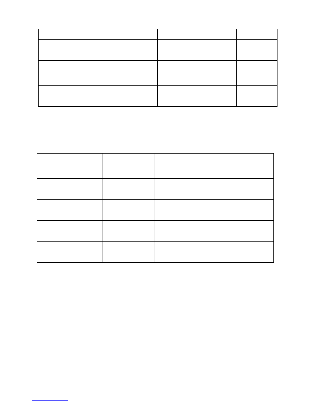
1.2 Specifications
Specifications for SiE2900 and SiE3840
Name-Pa rt nu mber SiE2900 SiE3840
Grid output (AC)
Grid voltage, nominal 240/208 VAC
Grid voltage, operating range
211~264@240VAC(adjustable) *
183~228@208VAC (adjustable)*
Grid frequency, nominal 60 Hz
Grid frequency, operating range 59.3~60.5 Hz (adjustable)*
Maximum output power
2900W@240VAC
2700W@208VAC
3840W@240VAC
3330W@208VAC
Maximum output current 13 A 16.3 A
Output over current protection 20A 20 A
Maximum output fault current 15A 20 A
Startup current < 2 A
Maximum grid backfeed current 0 A
Waveform True sine
Power factor >0.99 @ nominal power
Total Harmonic Distortion
<3%
DC Component <0.5%
Phase Split Phase or Single phase 240
Solar input (DC)
Input voltage range 200~550 VDC
Maximum input voltage 600 VDC
PV start voltage 235 VDC (adjustable)
Maximum input current 16 A 20 A
Maximum input short circuit
current
24A
18
Name-Pa rt nu mber SiE2900 SiE3840
Solar input (DC)
Number of fused string inputs 3 4
Efficiency
Maximum efficiency
96.7%@240VAC
96.4%@208VAC
96.7%@240VAC
96.5%@208VAC
CEC efficiency
96.0%@240VAC
95.5 %@208VAC
96.0%@240VAC
95.5%@208VAC
Night-time tare loss 0.5W
Environmental
Operating temperature range -25° ~ +55°C (-13° ~ +131°F)
Storage temperature range -25° ~ +55°C (-13° ~ +131°F)
Maximum full power operating
ambient
55°C (131°F) 55°C (131°F)
Relative humidity
Max. 95%
Mechanical
Outdoor enclosure NEMA 3R, Rainproof
Cooling Natural Cooling fan
Input and output terminals
Accept wire size of 4 to 16 mm2
(#12 to #6 AWG)
Weight/Shipping weight 23 kg / 27 kg (50.7 lb / 59.5 lb)
Dimensions (HxWxD) 732x454x175 mm (28.8x17.9x6.9 inches)
Shipping dimensions (HxWxD) 840x540x275 mm (33.1 x21.3x10.8 inches)
Interface
Communication RS232 and RS485 (Option with wireless)
Display LED/LCD
Positive ground inverters
Model name SiE2900-PG SiE3840-PG
Certifications
UL 1741, FCC Part 15 B, IEEE 1547, IEEE C62.41.2, IEEE C37.90.1
19
* Factory settings can be adjusted with the approval of the utility. This unit
is provided with adjustable trip limits and may be aggregated above
30kW on a single Point of Common Coupling.
Adjustable voltage, Frequency and Reconnection Settings
Setting Range Default Accuracy
Over-voltage (%) 108.75~110 110 ±1
Under-voltage (%) 85~90 88 ±1
Over-voltage Reconnect voltage* (%)
105.83~110 105.83 ±1
Under-voltage Reconnect voltage* (%)
85~91.67 91.67 ±1
Over-frequency (Hz) 60.4~61 60.49 ±0.02
Under-frequency (Hz) 57~59.8 59.31 ±0.02
Over-voltage clearing time (cycle)
59~120 59 ±1
Under-voltage clearing time (cycle)
119~300 119 ±1
Over-frequency clearing time (cycle)
9~12 9 ±1
Under-frequency clearing time (cycle)
9~18000 9 ±1
AC high-voltage limit (%)
100~110 109 ±1
Reconnect delay** (s) 10~600 20 ±0.01
PV start voltage (VDC) 200~600 235 ±2
* The default values are within the Range B of ANSI C84.1
** Once a grid failure, the SiE Inverter waits 300 seconds before the next
connection to the grid.
20
Measurement precision
Range
Resolution
Accuracy
Display Measurement
Input voltage (VDC)
0~640V 0.1V 0.6V ±2V
Input Current (IDC)
0~23000mA 100mA 23mA ±200mA
Grid voltage (VAC)
0~300V 0.1V 0.6V ±1V
Grid current (IAC)
0~19000mA 100mA 38mA ±200mA
Grid frequency (Hz)
45~65Hz 0.1Hz 0.004Hz ±0.02Hz
Output power (W)
0~5000W 1W 1W ±30W
Energy yield (kWh)
0~9.99×10
6
kWh 0.1kWh 2.2×10⁻⁶kWh 1%
Operating hours (h)
0~65535H 1H 1s 0.03%
Specifications for SiE4900 and SiE5300
Name-Pa rt nu mber SiE4900 SiE5300
Grid output (AC)
Grid voltage, nominal
240/208 VAC
Grid voltage, operating range 211~264@240VAC(adjustable) *
183~228@208VAC (adjustable)*
Grid frequency, nominal
60 Hz
Grid frequency, operating range
59.3~60.5 Hz (adjustable)*
Maximum output power
4900W@240VAC
4300W@208VAC
5300W@240VAC
4600W@208VAC
Maximum output current
20.7A 22.1A
21
Output over current protection
30A
30A
Maximum output fault current
25A
25 A
Name-Pa rt nu mber SiE4900 SiE5300
Grid output (AC)
Startup current
< 2A
Maximum grid backfeed current
0 A
Waveform
True sine
Power factor
>0.99 @ nominal power
Total Harmonic Distortion
<3%
DC Component
<0.5%
Phase
Split Phase or Single phase 240
Solar input (DC)
Input voltage range
200~550 VDC
200~550 VDC
Maximum input voltage
600 VDC
PV start voltage
235 VDC (adjustable)
Maximum input current
25 A
25A
Maximum input short circuit
current
30A
Number of fused string inputs 4
Efficiency
Maximum efficiency
96.6%@240VAC
96.4%@208VAC
96.4%@240VAC
96.2%@208VAC
CEC efficiency
96%@240VAC
96%@208VAC
96%@240VAC
95.5%@208VAC
Night-time tare loss
0.5W
Environmental
Operating temperature range
-25° ~ +55°C (-13° ~ +131°F)
Storage temperature range
-25° ~ +55°C (-13° ~ +131°F)
Maximum full power operating
ambient
55°C (131°F) 53°C (127.4°F)
Relative humidity
Max. 95%
Mechanical
Outdoor enclosure
NEMA 3R, Rainproof

22
Cooling
Cooling fan
Input and output terminals
Accept wire size of 4 to 16 mm
2
(#12 to #6 AWG)
Name-Pa rt nu mber SiE4900 SiE5300
Mechanical
Weight/Shipping weight
28 kg / 32 kg (61.7 lb / 70.5 lb)
Dimensions (HxWxD)
732x454x210 mm (28.8x17.9x8.3 inches)
Shipping dimensions (HxWxD)
840x548x305 mm (33.1x21.6x12 inches)
Interface
Communication
RS232 and RS485 (Option with wireless)
Display
LED/LCD
Positive ground inverters
Model name SiE4900-PG SiE5300-PG
Certifications
UL 1741, FCC Part 15 B, IEEE 1547, IEEE C62.41.2, IEEE C37.90.1
* Factory settings can be adjusted with the approval of the utility. This unit
is provided with adjustable trip limits and may be aggregated above
30kW on a single Point of Common Coupling.
Adjustable voltage, Frequency and Reconnection Settings
Setting Range Default Accuracy
Over-voltage (%)
108.75~110
110
±1
Under-voltage (%)
85~90
88
±1
Over-voltage Reconnect voltage* (%)
105.83~110
105.83
±1
Under-voltage Reconnect voltage* (%)
85~91.67 91.67 ±1
Over-frequency (Hz)
60.4~61
60.49
±0.02
Under-frequency (Hz)
57~59.8
59.31
±0.02
Over-voltage clearing time (cycle)
59~120
59
±1
23
Under-voltage clearing time (cycle)
119~300
119
±1
Over-frequency clearing time (cycle)
9~12
9
±1
Under-frequency clearing time (cycle)
9~18000
9
±1
Setting Range Default Accuracy
AC high-voltage limit (%)
100~110 109 ±1
Reconnect delay** (s)
10~600
20
±0.01
PV start voltage (VDC)
200~600
235
±2
* The default values are within the Range B of ANSI C84.1
** Once a grid failure, the SiE Inverter waits 300 seconds before the next
connection to the grid.
Measurement precision
Range
Resolution
Accuracy
Display Measurement
Input voltage (VDC)
0~640V
0.1V
0.6V
±2V
Input Current (IDC)
0~31000mA
100mA
31mA
±300mA
Grid voltage (VAC)
0~300V
0.1V
0.6V
±1V
Grid current (IAC)
0~26000mA
100mA
52mA
±250mA
Grid frequency (Hz)
45~65Hz
0.1Hz
0.004Hz
±0.02Hz
Output power (W)
0~7800W
1W
1W
±40W
Energy yield (kWh)
0~9.99×10⁶kWh
0.1kWh
2.2×10⁻⁶kWh
1%
Operating hours (h)
0~65535H
1H
1s
0.03%
1.3 Accessories
Operation Manual 1 pc
24
2. Installation
2.1 Placement
∙ SiE Inverters that must be vertically mounted and may be located indoors or
outdoors, according to protection class Type N EMA 3R.
∙ Leave at least 50 cm (19.7 inches) of free space above and 100 cm (39.4
inches) below the inverter when installed outdoors. Allow 20 cm (7.9 inches)
between inverters when installing multiple inverters for better ventilation
(see figure 2.1.1).
∙ Mount the inverter on a wall that is strong enough to sustain the inverter
with a 32 kg (70.5 lb) weight.
∙ Avoid mounting the inverter in a location directly exposed to sunlight and
maintain the ambient temperature of the inverter within -25° and 55 °C (-13°
and 131°F). Humidity shall be within 0% and 95%.
WARNING!
DO NOT operate the inverter where exposed to flammable,
explosive environment or around combustibles like trash or
unknown materials that may result in danger. Some parts of
the cooling surface can reach temperatures over 70°C (158°F).
WARNING!
DO NOT expose the inverter to the corrosive liquids and/or
gases.

25
∙ Keep DC wiring as short as possible to minimize power loss.
∙ The mounting bracket should be fastened on a concrete or a masonry wall
with the accessory anchors.
Fig 2.1.1 Clearances required for SiE Inverter installation
2.2 Mounting
The steps listed below describe how to mount the inverter on the wall:
1. After removing the inverter from the carton, the attached mounting bracket
must be removed by sliding the bracket down and away from the inverter as
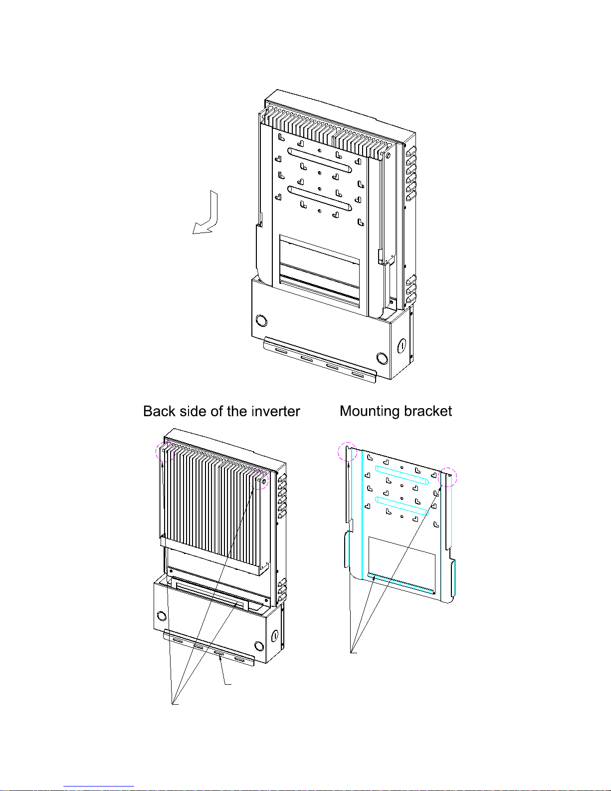
26
shown in the figure 2.2.1 be low.
Mounting flanges
Mounting flanges
Mounting slots for securing the inverter
27
Fig 2.2.1 Remove the bracket from the inverter
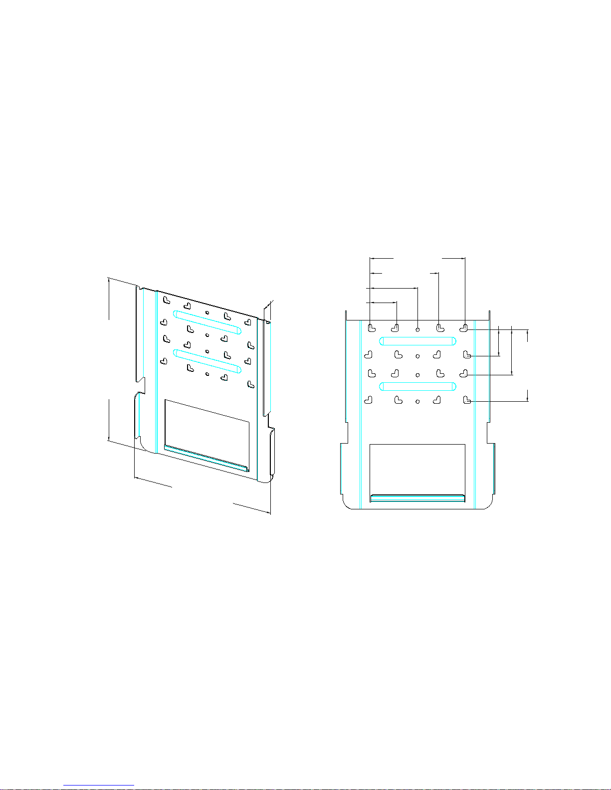
2. Use the bracket (figure 2.2.2) as a template to mark the location of the holes
to be drilled in the wall. After drilling the holes, the mounting bracket is
then held against the wall and fastened to the wall with anchors as shown in
figure 2.2.3. (A minimum of three (3) screws is required)
(7)/(2.76)
(12)/(4.72)
(19)/(7.48)
unit:cm/ inch
(40.5)/(15.94)
(52.5)/(20.67)
(4.4)/(1.73)
(7)/(2.76)
(12.5)/(4.92)
(18)/(7.08)
(25)/(9.84)
Fig 2.2.2 Inverter mounting bracket
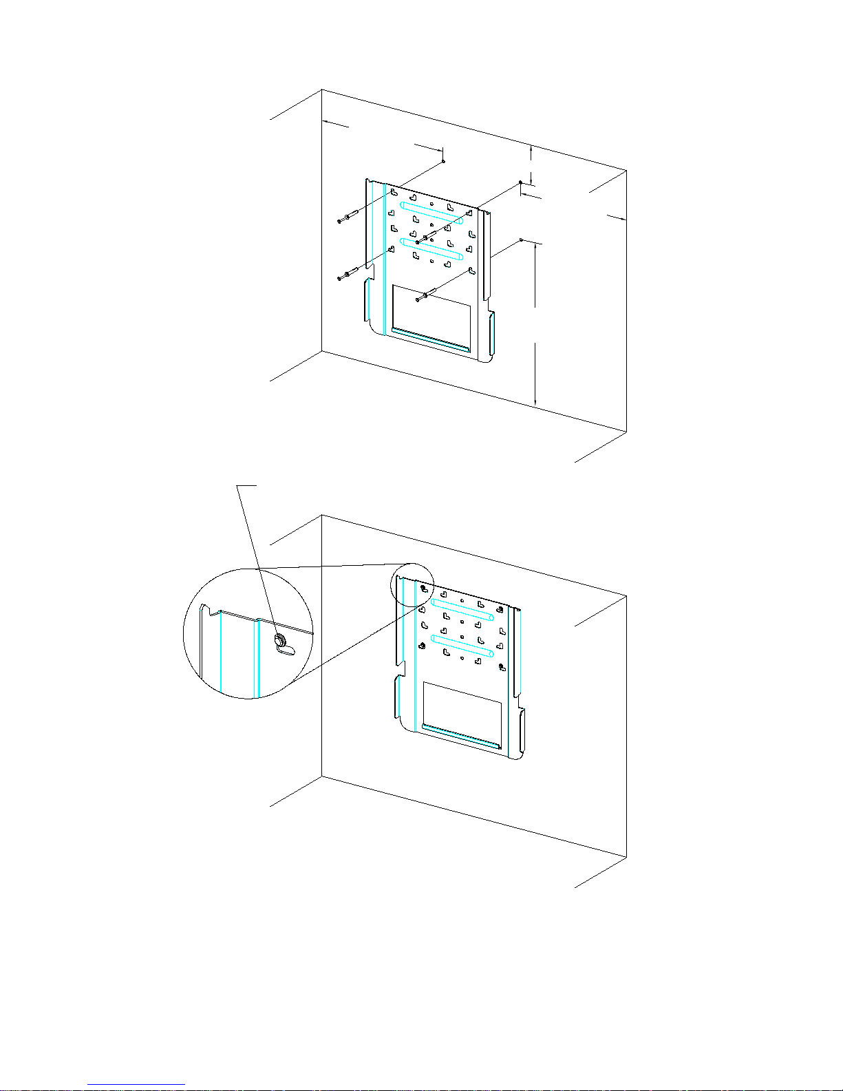
28
(60)/(23.62)
unit:cm/inch
(30)/(11.81)
(100)/(39.37)
~ (170)/(66.93)
(30)/(11.81)
The height of the anchor head < 8mm(0.314 i n)
Fig 2.2.3 Fasten the mounting bracket
 Loading...