

Page 1
OWNER’S MANUAL
GUIDE D’UTILISATION
MANUAL DEL
PROPIETARIO
Model • Modèle• Modelo
DKC646BLS
CAUTION:
Read and follow all safety rules
and operating instructions
before first use of this product.
PRÉCAUTION :
Veuillez lire attentivement les
consignes de sécurité et les
instructions d'utilisation avant
l'utilisation initiale de ce
produit.
PRECAUCIÓN:
Lea y observe todas las
reglas de seguridad y las
instrucciones de operación
antes de usar este producto
por primera vez.
Danby Products Limited, Guelph, Ontario Canada N1H 6Z9
Danby Products Inc., Findlay, Ohio USA 45840
draft.1.03.07
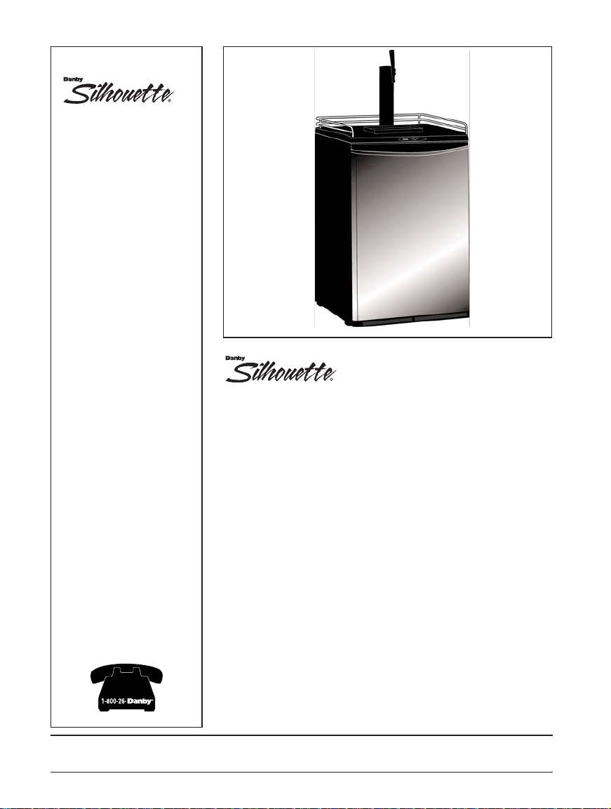
Keg Cooler
Owners Manual
Table of Contents . .......................3
Glacière de bière pression
Guide d'utilisation
Table des matières . . . . . . . . . . . . . . . . . . . . . ..23
Barril Refrigerador
Manual del propietario
Tabla de Contenido . . . . .......................43
R
?
Page 2
WELCOME
NEED HELP?
Welcome to the
Danby family. We’re
proud of our quality
products and we
believe in dependable
service.
You’ll see it in this
easy-to-use manual
and you’ll hear it in
the friendly voices of
our consumer service
department.
Tel: 1-800-26-
Best of all, you’ll
experience these
values each time you
use your Keg Cooler.
That’s important,
because your new
Keg Cooler will be
part of your family for
a long
time.
Before you call for service,
there are a few things you
can do to help us serve
you better...
Read this manual
It contains instructions to
help you use and maintain
your keg cooler properly.
If you received a
damaged appliance
Immediately contact the
dealer (or builder) that sold
you the appliance.
Save time and money
Check the section titled “If
Something Goes wrong”
before calling. This section
helps you solve common
problems that might occur.
If you do need service, you
can relax knowing help is
only a phone call away.
Tel: 1-800-26-
Write down the model and serial
numbers here. They are on a label
located on the back of the cabinet.
Model number DKC646BLS
Serial number
Date purchased
Staple your receipt to the inside
back cover of this page.You will
need it to obtain service under
warranty.
R
Start Here!…Before using your Keg Cooler
R
Page 3
Important Safety Information
Grounding Instructions 4
Warning C02Can be Dangerous! 4
Safety Precautions 5
Don’t Wait Do This Now! 5
Important Notice 5
Features
Knowing your Keg Cooler 6
Accessories 7
Capacity 8
Setting Up Your Keg Cooler
Before putting your appliance into use 9
Disposal of Packaging 9
Location 9
Outdoor Instructions 9
Assembly Instructions 10
Changing the Direction of the Door Swing 13
Castor Installation 13
Operation Instructions
Electronic Controls 14
Beer Temperature 14
Replace an Empty CO
2
Cylinder 15
Tap a Keg 15
Using Proper Draw Technique 16
Cleaning and Maintenance
Keg Cooler, Dispense System 17
Glassware, CO
2
Pressure, Beer Keg 18
Before You Call For Service
Troubleshooting 19
Warranty 20
4
6
9
14
TABLE OF CONTENTS
17
19
3
Page 4
IMPORTANT SAFETY INFORMATION
WARNING CO
2
CAN BE
DANGEROUS!
READ ALL SAFETY INFORMATION BEFORE USING
GROUNDING
INSTRUCTIONS
• This appliance must be grounded. In the event of a
malfunction or breakdown, grounding will reduce the risk
of electric shock by providing a path of least resistance
for electric current.
• This appliance is equipped with a power cord having an
equipment grounding conductor and grounding plug. The
plug must be plugged into an appropriate wall outlet that
is installed and grounded in accordance with all existing
local codes and ordinances.
• Consult a qualified electrician or serviceman if the
grounding instructions are not clearly understood, or if
doubt exist as to whether your electrical wall outlets are
properly grounded.
FOR YOUR
SAFETY...
Pertaining to the risk
of Fire, Electric Shock
or Injury to Persons.
1. Always connect a CO
2
gas cylinder to a regulator. Failure to do so could
result in an explosion
which can possibly result
in death or injury when the
cylinder valve is opened.
2. Never connect a C0
2
gas
cylinder directly to beer
keg.
3. Always secure a C0
2
gas
cylinder in an "upright"
position.
4. Always keep a CO
2
gas
cylinder away from heat.
5. Never drop or throw a
CO2gas cylinder.
6. Always check the D.O.T.
(Department of Transport)
test date located on the
neck of the cylinder before
installation. If over five (5)
years, do not use, return
the gas cylinder to gas
supplier.
CO2Cylinders when
charged contain high
pressure compressed gas
which can be hazardous if
not handled properly. Read
and understand the
following procedures for
CO
2
cylinders before
installation;
If it becomes difficult to
breathe and/or your head
starts to ache, abnormal concentrations of carbon dioxide
(CO
2
) may be present in the
area....
CLOSE THE MAIN VALVE ON
THE CO2CYLINDER,
VENTILATE AND LEAVE THE
ROOM IMMEDIATELY!
7. Never connect a product
container unless there
are two (2) safety
mechanism's in the
pressure system;
(a) One at or on the CO
2
regulator.
(b) One at or on the
product container coupler
in the pressure gas line.
NOTE:
The regulator and keg
coupler supplied with this unit
are inclusive of such safety
mechanisms.
8. CO
2
gas cylinders should
be stored in the coolest
part of the establishment
(preferably) at 70ºF (21ºC)
and must always be
securely fastened in an
"upright" position.
9. Always ventilate area after
any leakage of CO2.
WARNING
4
Page 5
IMPORTANT SAFETY INFORMATION
SAFETY
PRECAUTIONS
• Do not defrost this appliance using other
electric appliances (i.e. hair dryer) and never
attempt to scrape or remove ice/frost
from the evaporator (cold plate) with sharp
objects.
• Always disconnect the appliance from the
power supply before cleaning and/or
attempting repairs/servicing.
WARNING:
Repairs should be
performed by qualified service
personnel only.
DON’T WAIT,
DO THIS NOW!
Improper disposal of worn
out appliances pose a risk
of entrapment to children.
• If you have purchased this appliance to replace an old
one remove either the gaskets, latches, lids or doors
from the unused appliance. If it was equipped with a
door lock that cannot be opened from the inside, (lock
bolt) make sure the lock is removed, disabled or
destroyed before discarding, this will make it impossible
for children to accidentally lock themselves inside the
appliance and suffocate.
• The refrigerator system of this appliance is filled with
refrigerant and insulating substances which should be
treated and processed separately. Call your nearest
service agent or specialized servicing center. If you are
unable to locate one, contact your local authorities for
proper disposal instructions. Be careful not to damage
any of the refrigeration lines of the appliance.
Beer is easily available with Danby's new Keg Cooler, however,
it is not intended to be available to people under the legal age
to consume beer. A beer faucet lock kit for the purpose of
limiting access, is readily available and can be purchased
through our after sales service department (
see ‘Optional
Accessories’ on pg 7
).
Danby does not assume liability for the
unlawful use or consumption of the beer.
PLEASE DRINK RESPONSIBLY AND PLEASE DON'T
DRINK AND DRIVE!
IMPORTANT
NOTICE
• This appliance must be connected to a
properly grounded electrical outlet (
see
Grounding Instructions on pg. 4
)
• Do not operate this appliance if it has a
damaged power cord or plug.
• Do no use this product near water, for
example: in a wet basement, near a
swimming pool or sink.
5
!
Page 6
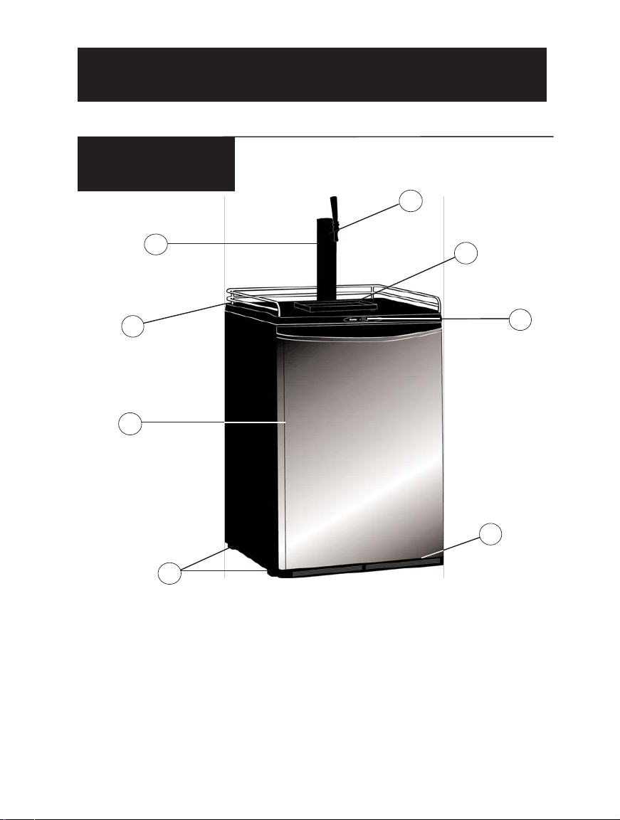
KNOWING YOUR
KEG COOLER
1
6
3
5
7
8
1 Black
Dispense Tower
2 Dispenser
Faucet & Handle
3 Plastic Drip Tray
FEATURES
4
2
4 Worktop &
Chrome Rail
5 Electronic
Controls/Display
6 Stainless Steel
Door
7 Intake/Exhaust
(for condenser fan)
8 Swivel Castors
6
Page 7
2 Chrome Rails (for attachment to Work top)
4 Self-Tapping Screws (to attach chrome rails)
1 CO2Cylinder Support Stand
1 CO2Cylinder (empty)
1 CO2Regulator (high/low pressure gauges)
1 CO2Air Line Hose
2 CO2Air Line Hose Connectors
1 CO2Air line hose plug
1 Beer Keg Coupler
1 Beer Tower Unit (incl. faucet, hose, nut and rubber washer)
4 Machine Screws (to attach to beer tower)
1 Gasket (beer tower base)
1 Pull Handle (beer tower faucet)
1 Protective Plate (refrigerator cabinet floor)
1 Plastic Drip Tray (2 piece)
4 Swivel Castors - 2 locking
16 Machine screws (for castor installation)
Description Part No.
Beer Faucet Lock. #7703
Beer Line Cleaning Kit. #CLEANINGKIT
For more details on purchasing any of the above listed
accessories, please contact our customer service
department
at 1-800-26- (1-800-263-2629).
FEATURES
INCLUDED
ACCESSORIES
Remove and inspect all
accessories supplied with
this unit are present and in
good condition. In the event
any of the accessories are
missing and /or not in good
condition, please call Danby
TOLL FREE at the number
listed below and speak with
one of our Customer
Service Representatives.
OPTIONAL
ACCESSORIES
These are NOT included with
the Keg Cooler, and must
be purchased separately.
7
R
Page 8
KEG SIZES
There are three (3) standard size beer kegs that can be
used in your Keg Cooler;
1/2 Barrel: 58.5 Liter Keg (15.5 Gal)
Yields: 7 cases (1984ozs) of beer
Keg Weight: 170lbs Full (approx.)
1/4 Barrel: 30 Liter Keg (7.75 Gal)
Yields: 3-1/2 cases (992ozs) of beer
Keg Weight: 85lbs Full (approx.)
1/6 Barrel: 20 Liter Keg (5 Gal)
Yields: 2-1/2 cases (640ozs) of beer
Keg Weight: 60lbs Full (approx.)
FEATURES
CO2 CYLINDER
A fully charged (5lb) CO2cylinder will service (approx.):
Quantity
Keg Size
10 58.5 Liter Kegs (1/2 Barrels)
20 30 Liter Kegs (1/4 Barrels)
25 20 Liter Kegs (1/6 Barrels)
For the location of a CO
2
supplier in your area,
(re-fills) please look in your "Yellow Page"
telephone directory under "OXYGEN" suppliers.
8
Page 9
OUTDOOR
INSTRUCTIONS
Direct Sunlight
The Keg Cooler should not be
exposed to direct sunlight.
Keep the Keg Cooler shaded.
Prolonged exposure to direct
sunlight may increase cooling
time and electricity consumption
(energy costs).
Extreme Temperatures
Operate the Keg Cooler in
ambient temperatures not less
than 10°C / 50°F or greater
than 40°C / 104°F.
Precipitation
The appliance should be
covered (protected) from any
precipitation.
IMPORTANT:
Do not
operate the Keg
Cooler outdoors unless
all of the conditions
outlined in this section
and in the Important
Safety Information
section are fully
satisfied.
SETTING UP YOUR KEG COOLER
LOCATION
• Selecting the proper location
will ensure peak performance
levels of your appliance.
Choose a location where the
unit will not be exposed to heat
emitting sources (e.g. a
fireplace or a barbeque).
• Do not use this product near
water, for example: in a wet
basement, near a swimming
pool or sink.
• This appliance is inclusive of
a condenser fan cooled
cabinet, the front intake and
exhaust should have 2-3
inches clearance in order to
maintain proper cooling.
DISPOSAL OF
PACKAGING
• Our products use
environmentally friendly
(recyclable) materials. To this
end, individual packaging
materials are clearly identified
with a recycling symbol.
Always use proper disposal
methods.
• When any appliance finally
wears out, always use safe
and proper disposal methods.
(
see “DON’T WAIT, DO THIS
NOW” on pg. 5
)
WE CARE ABOUT THE
ENVIRONMENT
Before putting the appliance into use...
If the appliance has recently been transported or tipped, before
connecting the appliance to any electrical power supply , leave it
standing (upright) for about 1 hour.This will reduce the possibility
of malfunctions in the cooling system due to transport handling.
Clean the appliance thoroughly, both interior and exterior. (
See
‘Cleaning and Maintenance’ on pg. 17
)
9
IMPORTANT:
• Ensure that all included
accessories are present and in
good condition (
see ‘Included
Accessories on pg. 7
).
• Make sure you have read
and understood all important
safety information on pages 4-
5.
Page 10
SETTING UP YOUR KEG COOLER
ASSEMBLY
INSTRUCTIONS
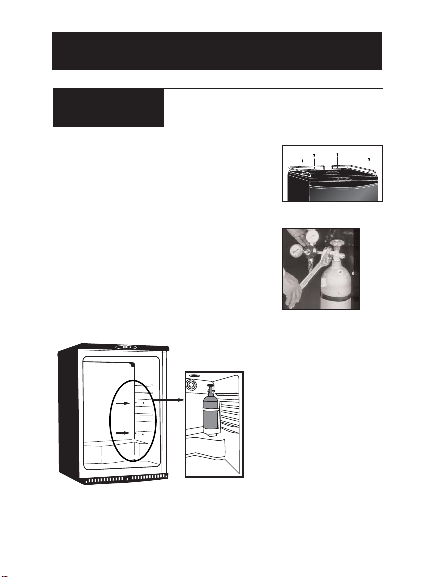
1. Installation of the Top Rail: See Fig. 1.
2. Installation of CO2 Regulator: Attach the CO2 Regulator to
the CO2 cylinder by screwing the regulator nut onto cylinder
valve and tighten (snug) using an adjustable wrench. See
Fig. 2.
IMPORTANT NOTICE: ALWAYS EXERCISE EXTREME
CAUTION WHEN HANDLING THE PRESSURIZED CO2
CYLINDERS.
3. Installation of CO2 Cylinder: Install your “fully charged”
CO2 cylinder into the support stand.
4. Installation of CO2 Cylinder Support: Align the holes in
the cylinder support stand with the studs and push down
firmly. See Fig. 3.
Fig. 2
10
R
Fig. 3
44
Fig. 1
Page 11
ASSEMBLY INSTRUCTIONS (CONT’D)
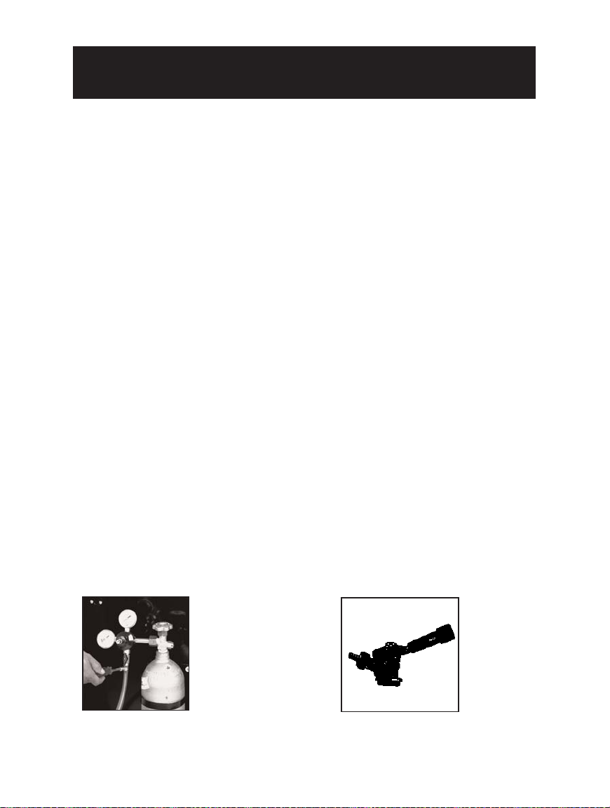
5. Installation of C02Air Line Hose to Regulator:
Attach one end of the (red) air line hose to the
hose barb connection on the CO2regulator.
Secure hose by using one of the two (self locking)
black plastic snap on clamps provided. (use pliers
to snap the clamp tight to
ensure that there are no
leaks) See Fig. 5
6. Installation of the Beer Tower Gasket: Position
the rubber (beer tower) gasket directly on top of
the cabinet aligning all four holes in the gasket
with the four holes on the cabinet.
7. Installation of the Beer Tower: Unravel the beer
line (hose) from the tower and insert the beer
line and nut through the gasket and into the
cabinet. Align the four holes in the base of the
beer tower, gasket and bayonet. The beer faucet
should be facing the front of the cabinet. (6:00
o'clock position) Using a Phillips Screwdriver,
attach the beer tower to the cabinet using the four
machine screws provided and tighten firmly.
8 . Installation of the Beer Tower Faucet Handle:
Screw the black faucet handle (clockwise) onto
the beer tower faucet. (hand tighten only)
9. Installation of the Keg Coupler: IMPORTANT
NOTICE;
Make sure the pull handle of the
keg coupler is in the "upward" (closed) position
before installing on the beer keg. See Fig. 6 Insert
the keg coupler into the locking neck of the beer
keg and apply a 1/4 turn clockwise to lock into
position.
10. Installation of the CO2Air Line Hose to the
Keg Coupler:
Attach the open end of the (red) air
line hose to the hose barb connection on the keg
coupler. Secure hose by using the remaining (self
locking) plastic snap on clamp provided. (use pliers
to tighten clamp and ensure there are no leaks)
11. Installation of the Beer Line Hose to the Keg
Coupler:
Screw the beer line nut onto the keg
coupler and hand tighten firmly. IMPORTANT
NOTICE: The black rubber washer provided must be
installed inside the beer line connection nut before
connecting the beer line to the keg coupler.
Fig. 5
SETTING UP YOUR KEG COOLER
11
Fig. 6
Page 12
13. Making the connection between the Keg
Coupler and Beer Keg:
Before making (opening)
connection between the keg coupler and beer keg,
make sure the beer tower faucet is in the closed
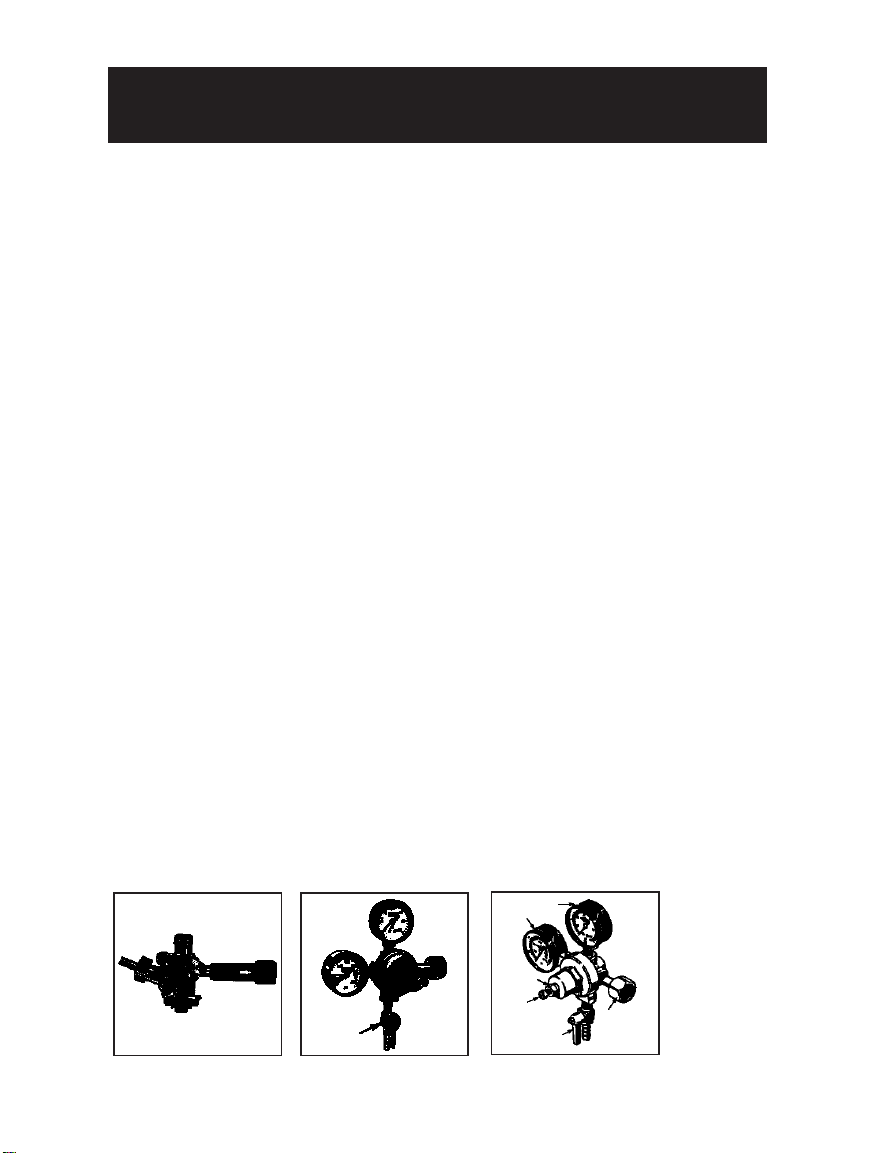
position. (faucet handle straight back) To engage
the tank connection, pull the keg coupler handle
out and push down until it locks into position.
Listen for positive "click" of the pull handle in the
final downward position. See Fig. 7
14. Opening the CO2Cylinder Main Valve: Before
opening the main valve located on top of the CO
2
cylinder, make sure the "secondary" shut-off valve
located on the lower stem pipe of the regulator is
in the "closed" position. See Fig. 8
NOTE: When the secondary valve (handle) is posi-
tioned "Horizontal" (east/west) the valve is closed.
When the secondary valve (handle) is positioned
"Vertical" (north/south) the valve is open.To open the
main CO2cylinder valve, slowly turn the main valve
counter clockwise until fully open.You will notice the
needles on both gauges start to climb.
15. Adjusting the CO2Regulator: There are two
pressure gauges on the CO2regulator.
See Fig. 9: The upper gauge #1 monitors "LOW"
(internal keg) pressure and must be adjusted to
the correct operating pressure of 10~12psi/lbs.The
lower gauge #2 monitors "HIGH" (CO2cylinder)
pressure and is not adjustable.The high pressure
gauge also acts as a fuel gauge to let you know
when the C02cylinder needs re-filling.
IMPORTANT: The internal operating pressure of the
beer keg should be adjusted and maintained between
10 ~ 12psi/lbs. To adjust the "low" pressure gauge;
• Using an adjustable wrench, release the adjustment
lock nut # 3. See Fig. 9
• Using a flat screwdriver, turn the regulator adjustment
screw (# 4 in Fig. 9): A clockwise rotation of the
regulator adjustment screw will increase low pressure,
a counter clockwise rotation of the adjustment
regulator adjustment screw will decrease low pressure
• When the required operating pressure is attained
retighten the adjustment lock nut # 3.
• You are now ready to serve cold beer
Fig. 7
Fig. 8
Fig. 9
2
1
4
5
6
3
Secondary
Shut-off
Valve
SETTING UP YOUR KEG COOLER
ASSEMBLY INSTRUCTIONS (CONT’D)
12
Page 13
SETTING UP YOUR KEG COOLER
13
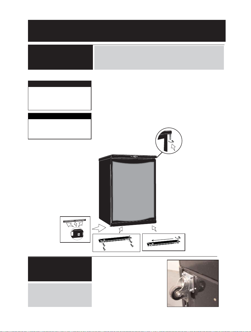
1. Unplug the keg cooler and
place the unit on its back..
2. Remove the kickplate by
removing the three retaining
screws (Fig. E1)
3. Remove the four screws
from the lower support
(
Fig.E2) and remove the
lower support.
4. Pull the door downward until
it releases from the upper
hinge pin.
5. Remove the plastic screw
caps from the top left hand
side and install it on the top
right hand side of the door
frame.
6 Unscrew the upper door
hinge pin (Fig E3) from the
right side of the worktop
and install it on the left side
of the worktop.
7. Position the main door on
the cabinet and push up
until the upper hinge pin is
inserted into the top of the
door.
8. Remove the lower support
pin from the lower support
and reposition it as shown
in Fig. E4).
9. Reinstall the
lower support pin on
the lower right side of
the door.
10. Make sure to align the door
with 1) the cabinet, and 2)
the lower support pin before
reinstalling the bottom-plate
and its four (4) screws.
11. Reinstall the kick-plate.
IMPORTANT!
Allow the unit to stand upright
for 1 hour before putting the
unit into operation.
WARNING!
Excessive Weight Hazard
Use two or more people to
move and install the keg
cooler.
Changing Direction
of the Door “Swing”
IMPORTANT NOTICE: Before proceeding with the configuration
options on this page, remove keg and the CO
2 cylinder (if installed)
from the Keg Cooler. Once complete, allow the unit to stand
upright for 1 hour before putting the unit into operation.
TOOLS REQUIRED: Phillips #2 screwdriver
Fig. E3
Fig. E2
Fig. E1
Fig. E4
Castor Installation
1. Lay the unit on it’s back.
2. Using the 16 machine screws
provided, install each of the 4
castors in the threaded holes
located in each corner of the
unit as shown in Fig.A.
Fig. A
The locking swivel castors
should be installed in the
front of the unit for easy
access.
R
44
Page 14
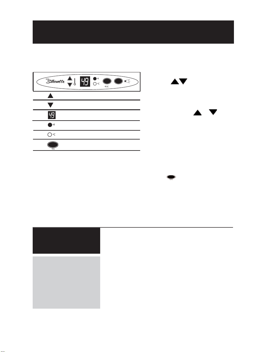
The electronic control panel allows for total cabinet
temperature control as well as the option of
displaying (current) and modifying (setting) the
cabinet temperature in either Fahrenheit or Celsius.
When you first plug in your Keg Cooler the LED will
display the ‘live’ cabinet temperature in Fahrenheit
and the thermostat will be set to 41º F (5º C). The
following paragraphs will explain how to modify the
aforementioned settings to suit your requirements;
Adjusting the temperature;
• Press either button once and release to
enter the ‘SET’ mode. The LED display will begin
to flash and show the previous temperature
setting - signifying the temperature is ready to be
adjusted.
• Each depression of the or will
increase or decrease the temperature
incrementally by 1º (F/C) until the desired setting
is reached. The temperature can be set between
36-46º F (2-8º C).
*Note: the display will flash for 5 seconds from
the time the last button was activated before
resuming display of the internal temperature of
the cabinet.
Changing the temperature display;
• Press the selector button to alternate the
display between Fahrenheit and Celsius. The
corresponding pilot light adjacent to the selector
will aluminate to signify which unit of temperature
has been selected for display.
* Please Note: In the event of a power failure,
any modified settings are lost and the default
settings are restored once power resumes.
OPERATING INSTRUCTIONS
Correct consistent temperature is an important factor
to consider when storing
and dispensing draught
beer. Therefore, please
adhere to the following
guide lines;
Electronic Controls
Beer Temperature
• Beer can freeze, so it is important to select and
maintain proper operating temperatures inside
the refrigerator cabinet. * Beer will start to
freeze at 28º F ( - 2º C)
• Optimum temperatures for serving cold beer are
36º ~ 40º F (2º ~ 4º C)
• Temperatures too cool or too warm may cause
flavor loss, off taste and dispensing problems.
• Periodically monitor temperatures inside your keg
cooler (adjust as necessary).
• Keep the keg cooler door closed as much as
possible to avoid temperature fluctuations.
14
TEMPERATURE INCREASE
TEMPERATURE DECREASE
LED DISPLAY
FAHRENHEIT MODE
CELSIUS MODE
FAHRENHEIT/CELSIUS SELECTOR
Page 15
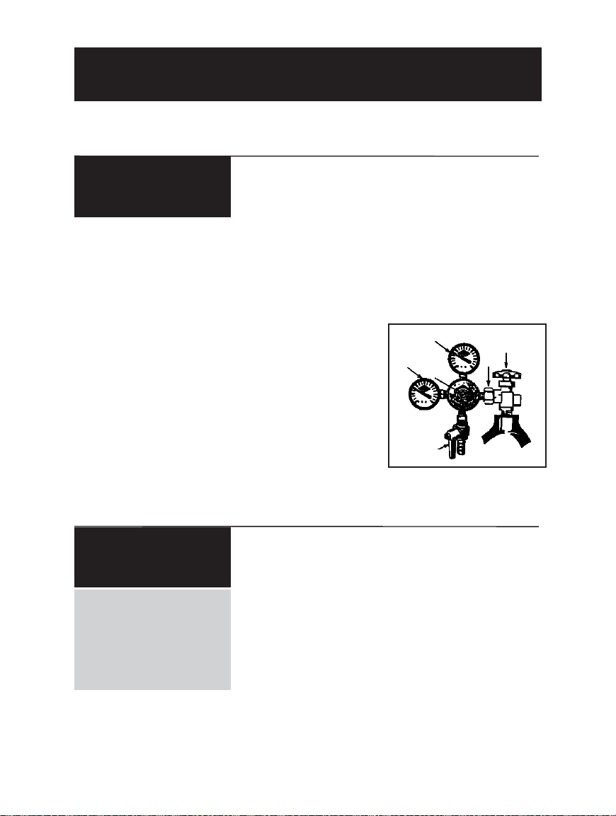
1. Close the main cylinder valve (A) by turning in a
clockwise direction. See Fig.12
2. Close the secondary shut-off valve (C) by
turning to "horizontal" (east/west) position on
lower stem pipe. See Fig.12
3. Remove the air line clamp and hose from the
regulator.
4. Remove the regulator assembly (E) from empty
cylinder. See Fig.12
5. Remove dust cap from new and/or replacement
CO2cylinder
6. Re-attach regulator assembly (E) to
new/replacement cylinder. See Fig.12
7. Re-attach the air line hose to regulator (barb
connection) and secure with clamp.
8. Slowly open main valve (A) all the way.
See Fig. 12
9. Readjust regulator pressure (D) (if necessary)
between 10 ~ 12 psi/lbs.
10. Open the secondary shut-off valve (C)by turning
to "vertical" (north/south) position on lower stem
pipe.
Fig. 12
D
B
C
E
A
F
OPERATING INSTRUCTIONS
Replace an Empty
CO
2
Cylinder
Tap a Keg
IMPORTANT: Do not agitate
kegs unnecessarily. If any
agitation occurs (during
transportation or installation) allow keg to settle for
1 ~ 2 hours before tapping.
• Prior to tapping the keg, ensure the beer faucet is in
the off position.
• Completely remove the dust cover (identification cap)
from the beer keg.
• Check that the keg coupler (handle) is in the up (off)
position. See Fig. 6
• Insert the keg coupler into the locking neck of the beer
keg and apply a turn clockwise to lock into position.
• Pull keg coupler handle out and downward until it locks
into position. See Fig. 7 This activates both the beer and
(CO2) pressure line.
The keg is now tapped and ready to draw beer.
15
Page 16
OPERATING INSTRUCTIONS
Using Proper Draw
Technique
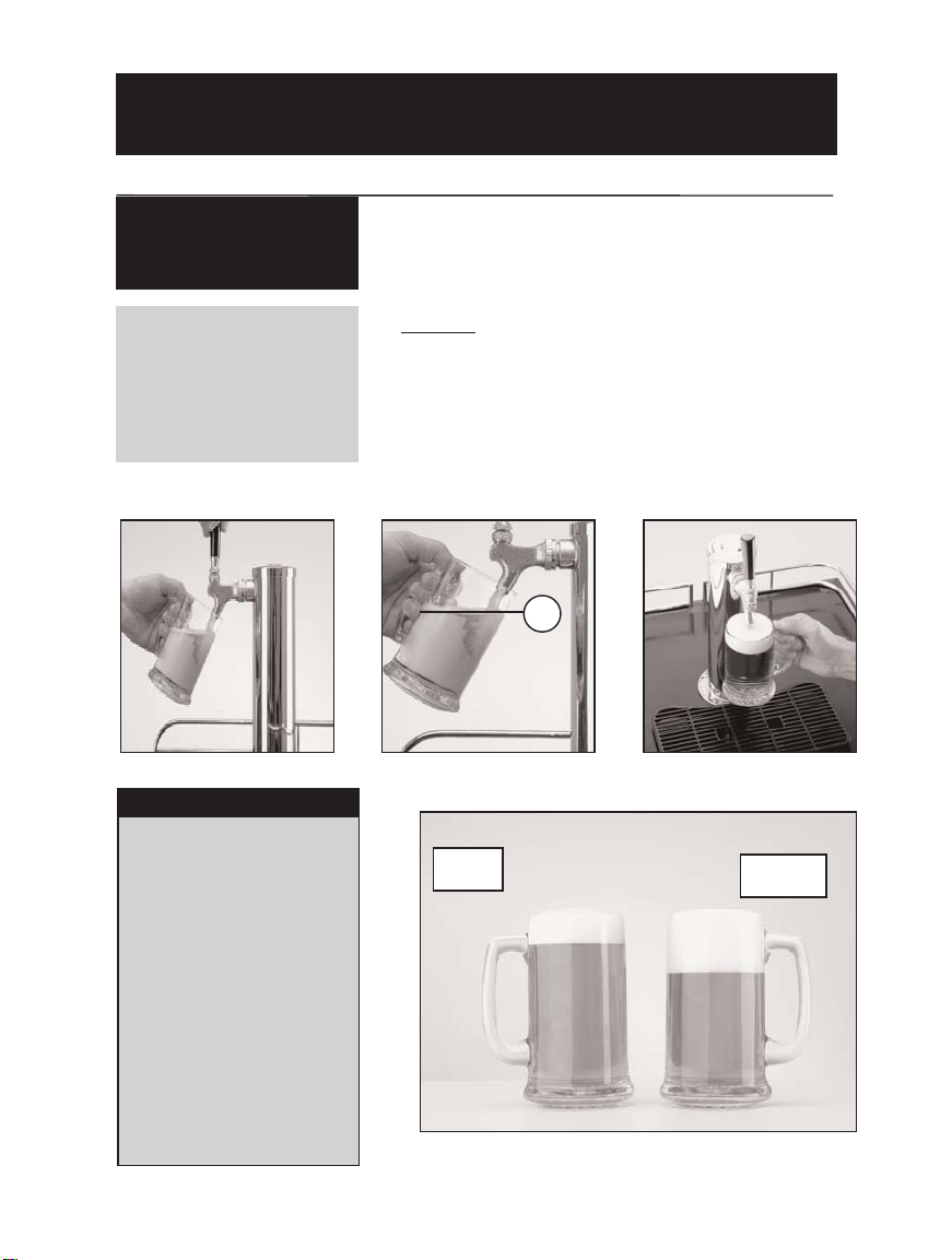
1. Rinse a “Beer Clean” glass under cold water.
2. Place glass beneath tap, and tilt at a 45
o
angle. (as
shown in Fig. 13) Leaving approximately 1/4” between
glass and faucet.
3. Fully draw the dispenser handle and fill the glass to 2/3
full. (as shown in Fig. 14).
4. Level the glass and finish topping off by continuing the
pour in the center of the glass. (as shown in Fig. 15)
5. Make sure the handle is fully returned to it’s previous
‘off’ position when the draw is complete.
Using the proper draw
technique to dispense beer
should allow you to fill an
8 oz glass leaving approxi
mately 3/4”- 1” of ‘foam’.
Fig. 13
Fig. 14
Fig. 15
DO NOT.....
Correct
Draw
Incorrect
Draw
Fig. 16
16
• Begin the draw with the
glass in an upright position.
• Use frosted glassware, as
the difference in temperature
between a frozen glass and
the beer in the keg can
cause a ‘wild’ draw (too
much foam).
• Partially (or slowly) draw the
dispenser handle, this will
lead to unnecessary
turbulence in the
dispenser
faucet as the beer travels
through it, causing a
substantial amount of foam
in the glass.
2
/
3
Page 17

CLEANING AND MAINTENANCE...
Regular cleaning and maintenance is a key factor in safe guarding the longevity of
the keg, the quality of the dispensed beer as well as trouble free day to day operation
of
your Keg Cooler.
...of the Keg
Cooler
• There is no need to defrost the refrigerator, because ice
depositing on the evaporator is defrosted automatically. Ice
build-up on the evaporator during compressor operation;
will (when the compressor has cycled off) defrost automatically.
Defrost water collects inside the drain trough and
passes through the drain outlet in the rear wall into a drain
pan situated above the compressor, where it evaporates.
• Always disconnect the power cord before cleaning and/or
servicing the appliance. Do not use coarse or aggressive
cleaning agents as they can damage the control panel
and/or painted surfaces. Clean the exterior cabinet with
warm water and a mild detergent. Clean the interior with
warm water and a mild detergent, adding one or two
spoonfuls of vinegar. After cleaning, connect the appliance
to power supply.
• If you do not intend to use the appliance for long periods of
time, disconnect the power cord. Clean the appliance and
leave the door slightly open to reduce mold/mildew from
accumulating inside the cabinet.
Beer lines have to periodically be cleaned because of a crystallized build up which forms on the fittings,
lines and taps commonly referred to as “beerstore”. If the “beerstore” is not completely removed in a
cleaning process it will leave an unsanitary surface that can harbor microorganisms which will cause an
undesirable flavor and/or cause the beer to go flat. Sufficient “beerstore” will also lead to dispense
problems ranging from ‘wild’ beer (too much foam) to flat beer, regardless of the carbonation levels or
quality (age) of the beer in the keg.
Scheduled line and faucet cleaning, with the proper equipment and chemical, eliminates the build-up of
“beerstore" protecting the integrity of the product and condition of the dispense system and seals. The
dispenser (beer) line should be cleaned approximately once every three (3) weeks or every other keg which ever comes first. The dispenser faucet should be cleaned on a weekly basis or prior to every use if
not used on a regular basis. Note: If you have trouble manipulating the faucet lever, this is usually
indicative that it may require cleaning. *
DO NOT
apply force to move the handle in this situation, as this will
likely lead to damaging the handle and/or faucet, and will not be covered by your warranty.
A standard cleaning kit will perform approximately eight (8) scheduled line cleanings.
Line cleaning kits are readily available and can be purchased through our after sales service department.
For more information please call 1-800 26-DANBY (1-800-263-2629)
... of the Dispense
System
17
Page 18

... of the “Beer
Clean” Glassware
CLEANING AND MAINTENANCE...
• Maintain strict sanitary conditions in the glass washing
area.
• Never wash glassware with utensils or dishes used to
serve food. Food particles and/or residue can effect the
quality/taste of draught beer.
• Regular dish detergents are fat-based and will leave a
slight oily film on the glass, which will cause the beer to go
flat quickly. Therefore, it is highly recommended that you
use a detergent that is designed specifically for beer glass
cleaning which is odor-free and non-fat based, instead of
regular liquid detergents.
• Avoid drying glassware with towels as they tend to leave
traces of lint on the surface of the glass.
• We recommend that you use beer glassware only for
beer.
Dairy and other food products leave a residue which can
effect the quality/taste of the draught.
... of the CO
2
Pressure
• Periodically monitor the pressure regulators to ensure applied
operating pressures remain constant. (10~12psi/lbs)
• Always keep equipment in good repair.
... of the Beer Keg
• Draught Beer should be immediately stored in a refrigerated
cabinet.
• Draught Beer products have a shelf life, which on "average"
is 30 days after the keg is tapped. By keeping the beer keg
pressurized, (with CO2) and with proper maintenance of the
dispense system, the shelf life can be extended to approximatly
60 days (or more).
• Beer Kegs should be stored (refrigerated) separately from
other food products.
Draught Beer should be treated as a food product.
It is very important that you
store and handle it properly.
18
Page 19
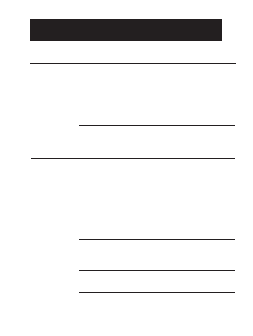
Problem Possible Causes What T o D o
Excess formation of
foam ‘head’.
Flat Draft, no
formation of foam.
No beer flow from
dispenser
Recent keg agitation
Improper regulator
setting
Internal temperature of
keg cooler (or beer keg)
too warm.
Pressure build up
Improper draw technique
Improper regulator
setting.
Glassware is not
“Beer clean”
Elongated dispensing
hose.
Low/Empty CO
2
cylinder.
Closed CO
2
valve and/or
shut-off valve.
Empty CO
2
cylinder.
Empty beer keg.
Line or dispenser
obstructions.
Improper connection(s)
If the keg has recently been moved (transported), you
should let it stand for a minimum of two (2) hours
before tapping.
Verify that the ‘LOW’ side (CO
2
) pressure is reading
between 10 ~ 12 p.s.i.
Ensure that the keg cooler is operating within 36 - 40
º
F (2-4º C). If the beer keg has been exposed to a
warm environment for an extended period, give it
sufficient time to cool before attempting a pour.
Activate the pressure relief valve that is located on the
keg coupler for 3 seconds.
see “Using Proper Draw Technique” on pg. 16.
Verify that the ‘LOW’ side (CO
2
) pressure is reading
between 10 ~ 12 p.s.i.
Residue on glassware in the form of oils will quickly
dissolve the formation of foam. (see “Beer Clean
Glassware” on pg. 18)
All recommended temperatures and gauge settings are
calculated for a dispensing hose five (5) feet in length.
Check that ‘HIGH’ pressure gauge is not reading “0”
p.s.i. Refill if necessary.
Ensure that both the CO
2
cylinder and regulator shut-
off valve are open.
Check that ‘HIGH’ pressure gauge is not reading “0”
p.s.i. Refill if necessary.
Replace beer keg.
Verify that there are no ‘kinks’ or obstructions in either
the air line (red) or dispenser line (clear) and that
neither are frozen.
Ensure all connections are secure and all seals are in
place and in good condition.
BEFORE YOU CALL FOR SERVICE
TROUBLESHOOTING
19
Page 20
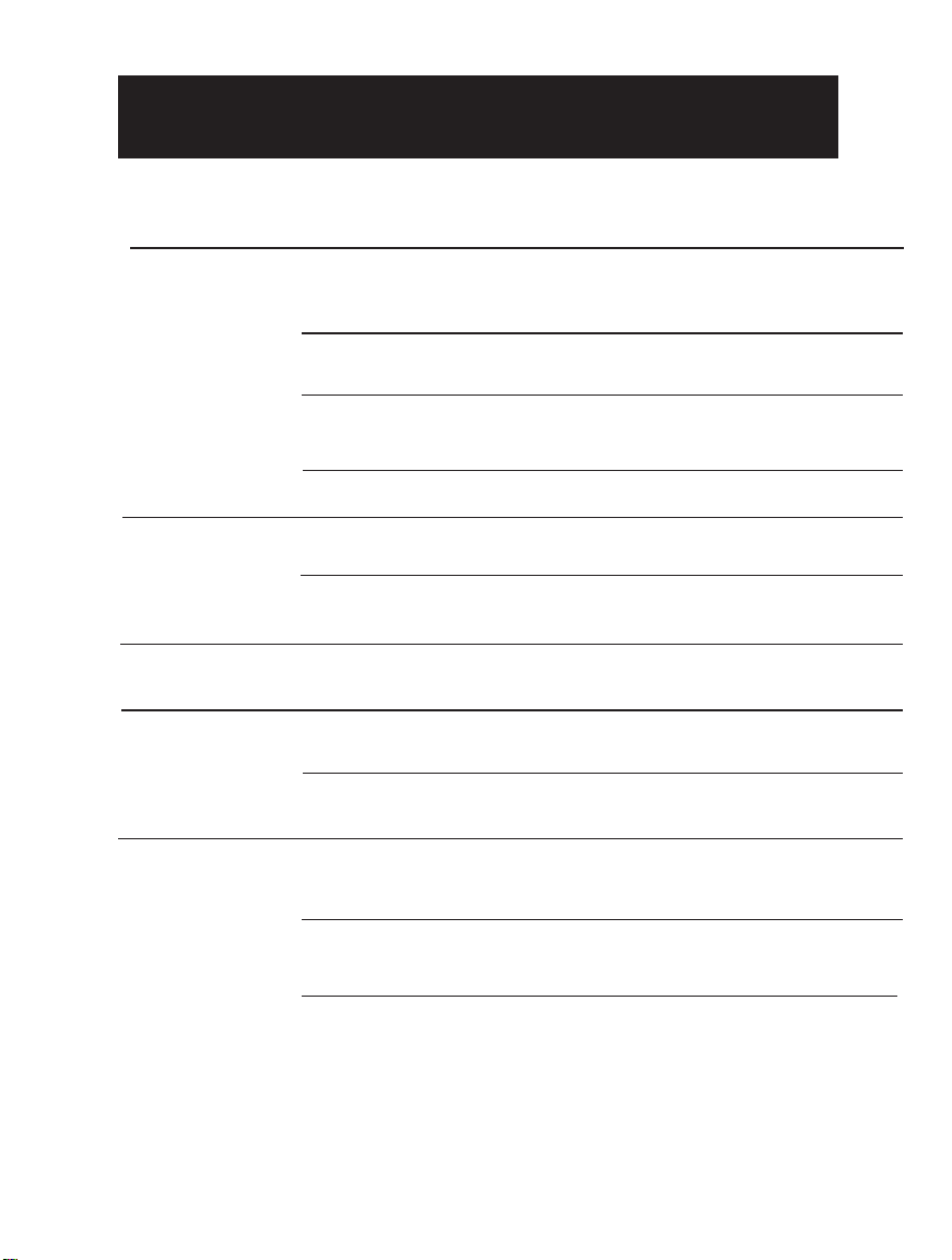
Problem Possible Causes What To Do
Sputtering draw
Faucet Dripping
Rapid C0
2
cylinder
discharge
Difficulty
Manipulating Faucet
handle
Abnormal beer
taste and/or smell
Dispense system
requires cleaning.
Keg Coupler installed
incorrectly
Line or dispenser
obstructions.
Improper draw technique
Handle not fully returned
to close position.
Faucet requires cleaning.
Improper connection, air
line leak.
Faucet requires cleaning
Damaged handle stem
Dispense system
requires cleaning.
Contaminated dispense
system.
The beer has exceeded
it’s shelf-life.
See “Cleaning and Maintenance” on pg. 17-18
Check seal between keg & faucet
Verify that there are no ‘kinks’ or obstructions in either
the air line (red) or dispenser line (clear) and that
neither are frozen.
see “Using Proper Draw Technique” on pg. 16.
After every pour, ensure the handle is returned to the
the off position.
See “Cleaning and Maintenance” on pg. 17-18
Ensure proper connection of air line at CO2 regulator,
and/or check air line for possible leaks
See “Cleaning and Maintenance” on pg. 17-18
Remove handle, and connector nuts and inspect stem
for possible damage.
See “Cleaning and Maintenance” on pg. 17-18
Check hoses for possible air leaks. Ensure all
connections are secure and all seals are in place and
in good condition.
Replace Beer Keg.
TROUBLESHOOTING (Cont’d)
BEFORE YOU CALL FOR SERVICE
20
Page 21
R
LIMITED PRODUCT WARRANTY
This quality product is warranted to be free from manufacturer’s defects in material and workmanship, provided that the unit is used under the normal operating
conditions intended by the manufacturer.
This warranty is available only to the person to whom the unit was originally sold by Danby or by an authorized distributor of Danby, and is non-transferable.
TERMS OF WARRANTY
Plastic parts (ie. evaporator door, door rails, covers and trays are warranted for thirty (30) days only from purchase date, with no extensions provided.
First Two Years
During the first two years (2), any electrical parts of this product found to be defective, including any sealed system units, will be repaired
or replaced, at warrantor’s option, at no charge to the ORIGINAL purchaser. Consumable parts (ie. light bulbs) are not warranted or
guaranteed for any length of time.
To obtain
Contact your dealer from whom your unit was purchased, or contact your nearest authorized Danby service depot, where service
Service
must be performed by a qualified service technician. If service is performed on the unit by anyone other than an authorized service
depot, or the unit is used for commercial application, all obligations of Danby under this warranty shall be at an end.
Nothing within this warranty shall imply that Danby will be responsible or liable for any spoilage or damage to food or other contents of this appliance, whether
due to any defect of the appliance, or its use, whether proper or improper.
EXCLUSIONS
Save as herein provided, Danby Products Limited (Canada) or Danby Products Inc. (U.S.A.), there are no other warranties, conditions, representations or
guarantees, express or implied, made or intended by Danby Products Limited or its authorized distributors and all other warranties, conditions, representations or
guarantees, including any warranties, conditions, representations or guarantees under any Sale of Goods Act or like legislation or statute is hereby expressly
excluded. Save as herein provided, Danby Products Limited (Canada) or Danby Products Inc. (U.S.A), shall not be responsible for any damages to persons or
property, including the unit itself, howsoever caused or any consequential damages arising from the malfunction of the unit and by the purchase of the unit, the
purchaser does hereby agree to indemnify and save harmless Danby Products Limited from any claim for damages to persons or property caused by the unit.
GENERAL PROVISIONS
No warranty or insurance herein contained or set out shall apply when damage or repair is caused by any of the following:
1) Power Failure.
2) Damage in transit or when moving the appliance.
3) Improper power supply such as low voltage, defective house wiring or inadequate fuses.
4) Accident, alteration, abuse or misuse of the appliance such as inadequate air circulation in the room or abnormal operating conditions,
(extremely high or low room temperature).
5) Use for commercial or industrial purposes.
6) Fire, water damage, theft, war, riot, hostility, acts of God such as hurricanes, floods etc.
7) Service calls resulting in customer education.
Proof of purchase date will be required for warranty claims; so, please retain bills of sale. In the event warranty service is required, present this document to our
AUTHORIZED SERVICE DEPOT.
Danby Products Limited
P.O. Box 1778, Guelph, Ontario, Canada N1H 6Z9
Telephone: (519) 837-0920 FAX: (519) 837-0449
Danby Products Inc.
P.O. Box 669, Findlay, Ohio, U.S.A. 45839-0669
Telephone: (419) 425-8627 FAX: (419) 425-8629
03/08
Warranty Service
In Home
21
Page 22
R
?
Model • Modèle• Modelo
DCK646BLS
For service, contact your nearest
service depot or call:
1-800-26- Danby
(1-800-263-2629)
to recommend a depot in
your area.
En cas de réparation, veuillez
contacter votre service
après-vente le plus près ou
communiquez au:
1-800-26- Danby
(1-800-263-2629)
pour connaître le service
après-vente le plus proche.
Para obtener servicio,
comuníquese con el
establecimiento de servicio
más cercano o llame al:
1-800-26- Danby
(1-800-263-2629)
para que le recomendemos un
establecimiento de su zona.
Keg Cooler
The model number can be found on the serial plate located on the
back panel of the unit.
All repair parts available for purchase or special order when you visit
your nearest service depot. To request service and/or the
location of the service depot nearest you, call the TOLL FREE
NUMBER.
When requesting service or ordering parts, always provide the
following information:
• Product Type
• Model Number
• Part Description
Glacière de bière en fût
Le numéro du modèle se trouve sur la plaque d'identification située
sur le panneau arrière de l'appareil.
Il est possible d'acheter les pièces de rechange ou de les obtenir par
commande spéciale en vous rendant à votre service après-vente le
plus proche. Pour effectuer des réparations ou obtenir l'adresse du
service après-vente le plus proche, veuillez composer le NUMÉRO
SANS FRAIS.
Pour effectuer des réparations ou commander des pièces de
rechange, veuillez donner les renseignements suivants :
• Type de modèle
• Numéro du modèle
• Description des pièces
Refrigerador de Barril
El número de modelo se encuentra en la placa de serie, ubicada en
el tablero posterior de la unidad.
Puede comprar todos los repuestos o hacer un pedido especial
visitando el establecimiento de servicio más cercano a su domicilio.
Llame al TELÉFONO GRATUITO para obtener servicio de
mantenimiento o la dirección del establecimiento de servicio más
cercano a su domicilio.
Siempre, al solicitar servicio de mantenimiento o hacer un pedido de
repuestos, debe suministrar la siguiente información:
• Tipo de artefacto
• Número de modelo
• Descripción del repuesto
Danby Products Limited, Guelph, Ontario Canada N1H 6Z9
Danby Products Inc., Findlay, Ohio USA 45840
Printed in China (P.R.C.) Imprimé en Chine (R.P.C.) Impresso en China (R.P.C.)
R
R
R
 Loading...