

Page 1

Wireless LAN Survey
NX-1
User's Guide
WA102930XB
Page 2

Copyright© 2017 silex technology, Inc. All rights reserved.
Page 3

Index
Introduction .............................................................................................. 1
1.
1-1. Introduction ...........................................................................................................................................1
Disclaimers ..................................................................................................................................................1
Trademarks .................................................................................................................................................1
1-2. Safety Instructions ...............................................................................................................................2
1-3. User Registration and Customer Services ...................................................................................5
User registration ........................................................................................................................................5
Product Information ................................................................................................................................5
Customer Support Center .....................................................................................................................5
About NX-1 ................................................................................................7
2.
2-1. Included Items .......................................................................................................................................7
2-2. Features ....................................................................................................................................................8
2-3. Limitations and Precautions .......................................................................................................... 10
Limitations ...............................................................................................................................................10
Precautions ..............................................................................................................................................10
2-4. Parts and Functions .......................................................................................................................... 11
2-5. Hardware Specication ................................................................................................................... 14
2-6. Software Specication ..................................................................................................................... 15
2-7. OpenSSL License ...............................................................................................................................16
Setup ......................................................................................................... 19
3.
Page 4

3-1.
Setup through the Web Page of NX-1 ........................................................................................................20
Connecting NX-1 to a Network .........................................................................................................20
Modifying PC Network Settings ....................................................................................................... 22
Setting up NX-1 ...................................................................................................................................... 23
Using NX-1 ......................................................................................................... 33
4.
4-1.
Collecting Wireless LAN Environment Information .....................................................................................33
Installing NX-1 in a Target Wireless LAN Environment to Collect Information ................ 34
4-2. Using the Survey Mode ................................................................................................................... 37
Running the Survey Mode through the Web Page ................................................................... 38
Viewing Survey Analysis Results ...................................................................................................... 41
Band Information - Band Occupy Ratio ......................................................................................... 43
Band Information - Device Count .................................................................................................... 44
Band Information - Frame Status ..................................................................................................... 46
Survey Conguration - Device Information ................................................................................. 48
Survey Conguration - List of Data on Storage .......................................................................... 50
Displaying Print Layout .......................................................................................................................53
4-3. Using the Monitoring Mode .......................................................................................................... 55
Running the Monitoring Mode through the Web Page ..........................................................56
Using the Control Switch to Run the Monitoring Mode .......................................................... 59
Viewing Monitoring Results...............................................................................................................61
Monitoring Conguration - Band Occupy Ratio .........................................................................63
Monitoring Conguration - Device Count ....................................................................................64
Monitoring Conguration - Frame Status ..................................................................................... 65
Monitoring Conguration - Frame Type ........................................................................................66
Changing Display Date ........................................................................................................................ 67
Changing Display Time ........................................................................................................................ 68
Displaying Print Layout .......................................................................................................................70
Page 5

4-4. Using the Spectrum Analyzer ....................................................................................................... 71
Running the Spectrum Analyzer through the Web Page ........................................................72
Viewing Measurement Results .........................................................................................................75
Spectrum Analyzer - Spectrogram .................................................................................................. 76
Spectrum Analyzer - Spectral Density ........................................................................................... 77
Deleting Measured Data ..................................................................................................................... 78
Displaying Print Layout .......................................................................................................................79
4-5. Using the Capture Mode .................................................................................................................80
Running the Capture Mode through the Web Page ................................................................. 81
Using the Control Switch to Run the Capture Mode ................................................................ 83
Viewing Captured Data .......................................................................................................................85
Downloading Captured Data ............................................................................................................ 87
Deleting Captured Data ...................................................................................................................... 89
Other Features ................................................................................................. 91
5.
5-1. Maintenance Feature ....................................................................................................................... 91
Restarting ................................................................................................................................................. 91
Factory Default Conguration .......................................................................................................... 94
Firmware Update ................................................................................................................................... 97
Appendix ......................................................................................................... 99
A.
A-1. Notes on Web Browsers ................................................................................................................100
A-2. List of All Settings ...........................................................................................................................101
Page 6

Page 7

1. Introduction
1.
Introduction
Thank you for purchasing Wireless LAN Survey NX-1 (called "NX-1" below).
1-1. Introduction
This manual provides information on how to congure and use NX-1.
Please read the Safety Instructions carefully before you begin.
Disclaimers
- The unauthorized transfer or copying of the content of this manual, in whole or in part,
without prior written consent is expressly prohibited by law.
- The content of this manual is subject to change without notice.
- This manual was prepared to accurately match the content of each OS, but the actual
information shown on the computer monitor may dier from the content of this manual
due to future OS version upgrades, modications, and other changes.
- Although every eort was made to prepare this manual with the utmost accuracy, Silex
Technology will not be held liable for any damages as a result of errors, setting examples,
or other content.
Trademarks
- Microsoft and Windows are registered trademarks of Microsoft Corporation in the United
States and/or other countries.
- Google Chrome is a trade mark or a registered trademark of Google Inc.
- Other company names and product names contained in this manual are trademarks or
registered trademarks of their respective companies.
1
Page 8
NX-1 User's Guide
1-2. Safety Instructions
This section provides the safety instructions for safe use of NX-1.
To ensure safe and proper use, please read the following information carefully before using
NX-1. The safety instructions include important information on safe handling of NX-1 and
on general safety issues. Please be sure to read this page before using.
< Indication of the warning >
Danger
Warning
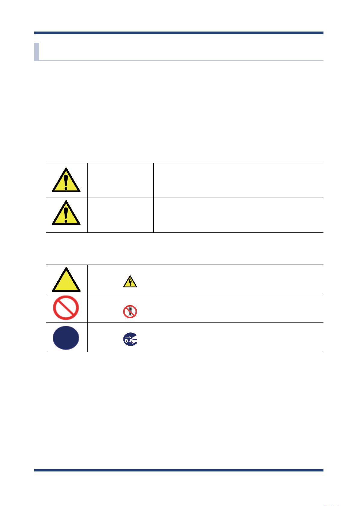
< Indication of the symbol >
This symbol indicates the warning and notice.
(Example: "Danger of the electric shock")
This symbol indicates the prohibited actions.
(Example: "Disassembly is prohibited")
This symbol indicates the necessary actions.
(Example: "Remove the AC plug from an outlet")
"Danger" indicates the existence of a hazard that
could result in death or serious injury if the safety
instruction is not observed.
"Warning" indicates the existence of a hazard that
could result in bodily injury and/or material damage
if the safety instruction is not observed.
2
Page 9
1. Introduction
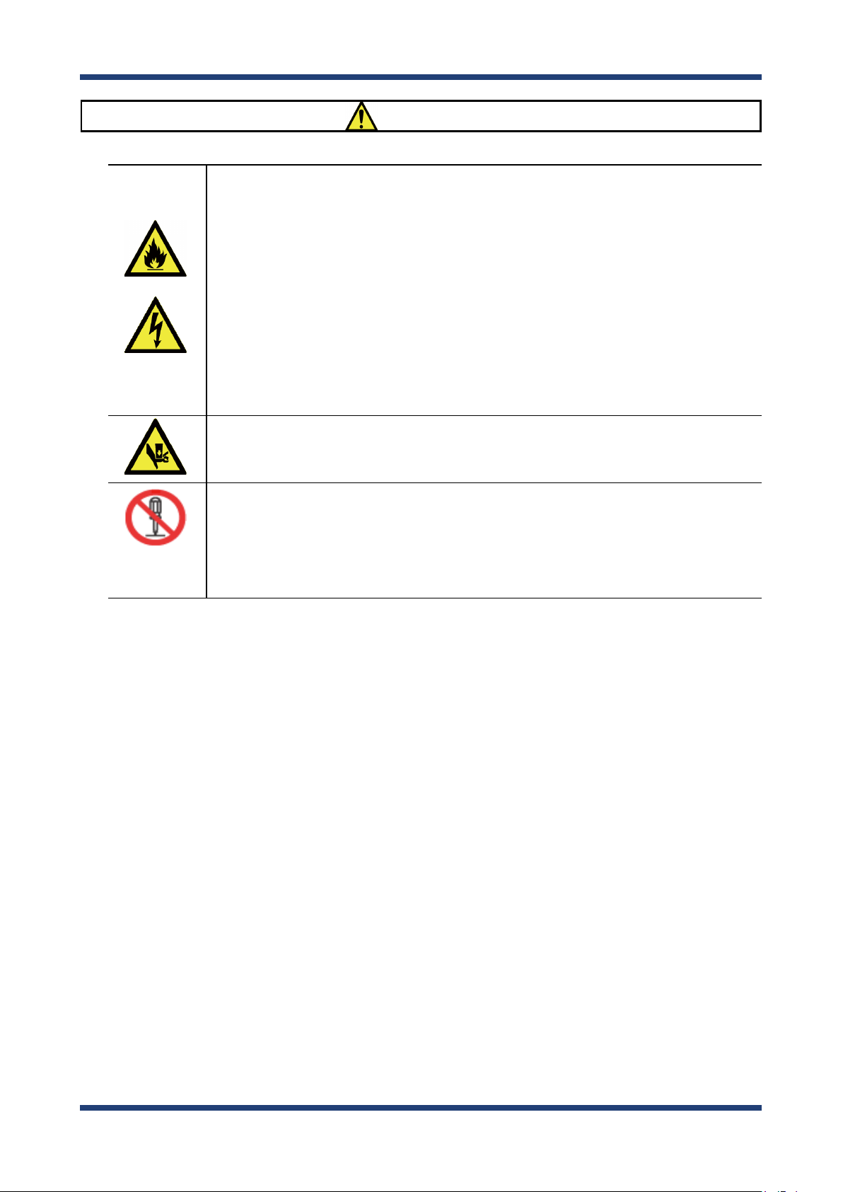
Danger
* Do not allow physical impact. When damaged, turn o your network device, unplug
the AC plug of NX-1 from power outlet (unplug the network cable from Ethernet HUB
when receiving power over the Ethernet) and contact your point of purchase. Failure
to take this action could cause re or an electrical shock.
* In the following cases, turn o your network device, unplug the AC plug of NX-1 from
power outlet (unplug the network cable from Ethernet HUB when receiving power
over the Ethernet) and contact your point of purchase for a repair or inspection.
Failure to take this action could cause re or an electrical shock.
* When NX-1 emits a strange smell, heat, or smoke.
* When foreign objects (liquid, metal, etc.) gets into NX-1.
* Keep the cord and cables away from children. They may be injured or receive a shock.
* Do not disassemble or modify NX-1. Doing so could result in re or an electrical shock,
or cause NX-1 to malfunction.
* Do not disassemble or alter the AC adapter bundled with NX-1. Doing so could result
in re or an electrical shock, or cause NX-1 to malfunction.
3
Page 10
NX-1 User's Guide
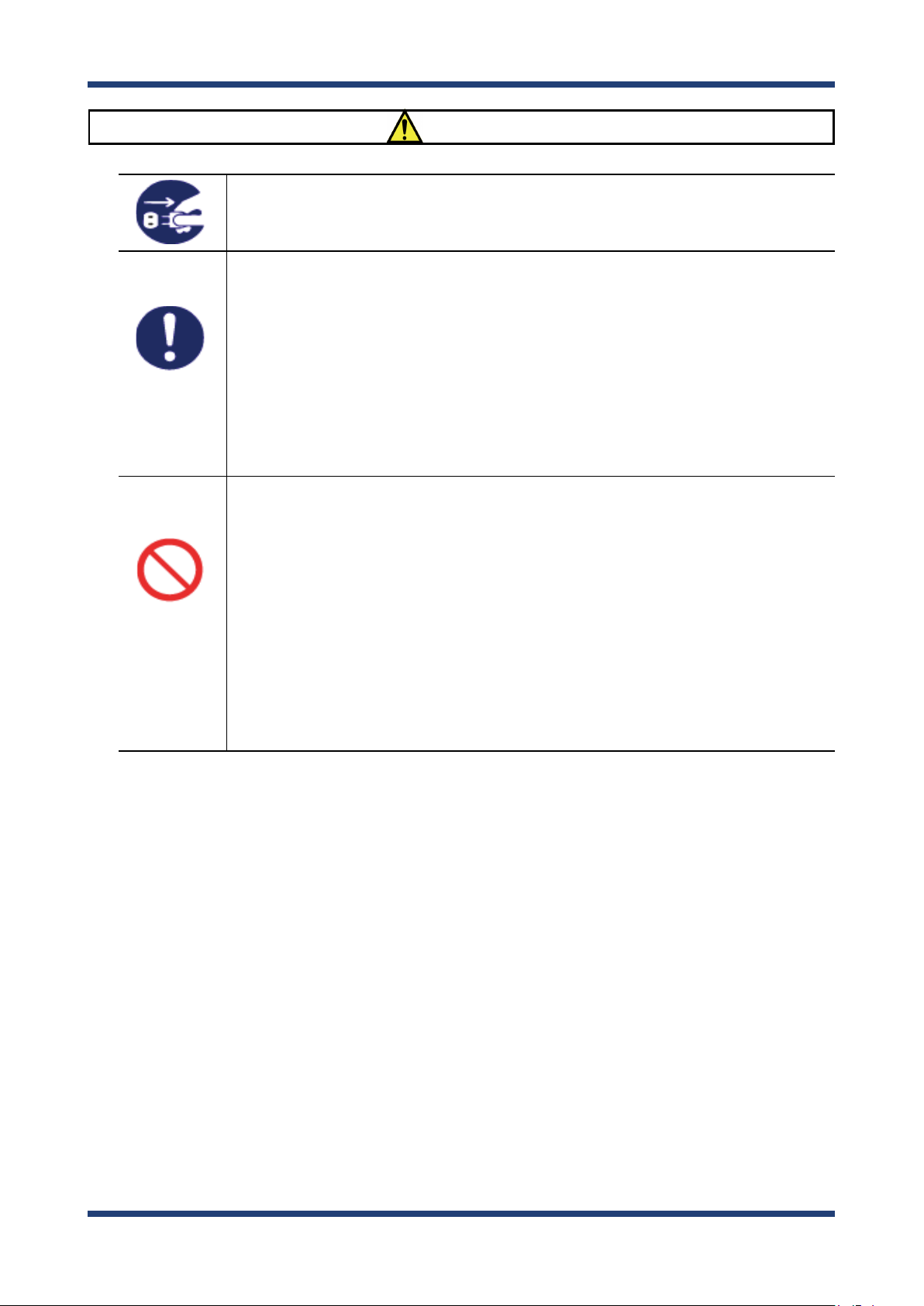
Warning
* When unplugging NX-1, do not pull on the cord.
The cord may break resulting in re and/or electric shock. Pull only on the plug.
* When moving NX-1, turn o connected devices and NX-1 by unplugging the power
cables from the outlet (if you are receiving power over the Ethernet (PoE), unplug the
network cable from the HUB).
* Always use the AC adapter bundled with NX-1. Other AC adapters may cause NX-1 to
malfunction.
* Verify all cables are connected properly and safely before using NX-1.
* When NX-1 will not be used for an extended time, unplug the power cables of
connected devices and NX-1.
* Do not use or store NX-1 under the following conditions to avoid potential damage to
NX-1.
- Hard vibrations
- Tilted places
- Unstable places
- Exposure to the direct rays of the sun
- Humid or dusty places
- Wet place (kitchen, bathroom, etc.)
- Heated places (near stove, heater, etc.)
- Wide temperature change
- Strong electromagnetic eld (near magnet, radio, wireless device, etc.)
4
Page 11
1. Introduction
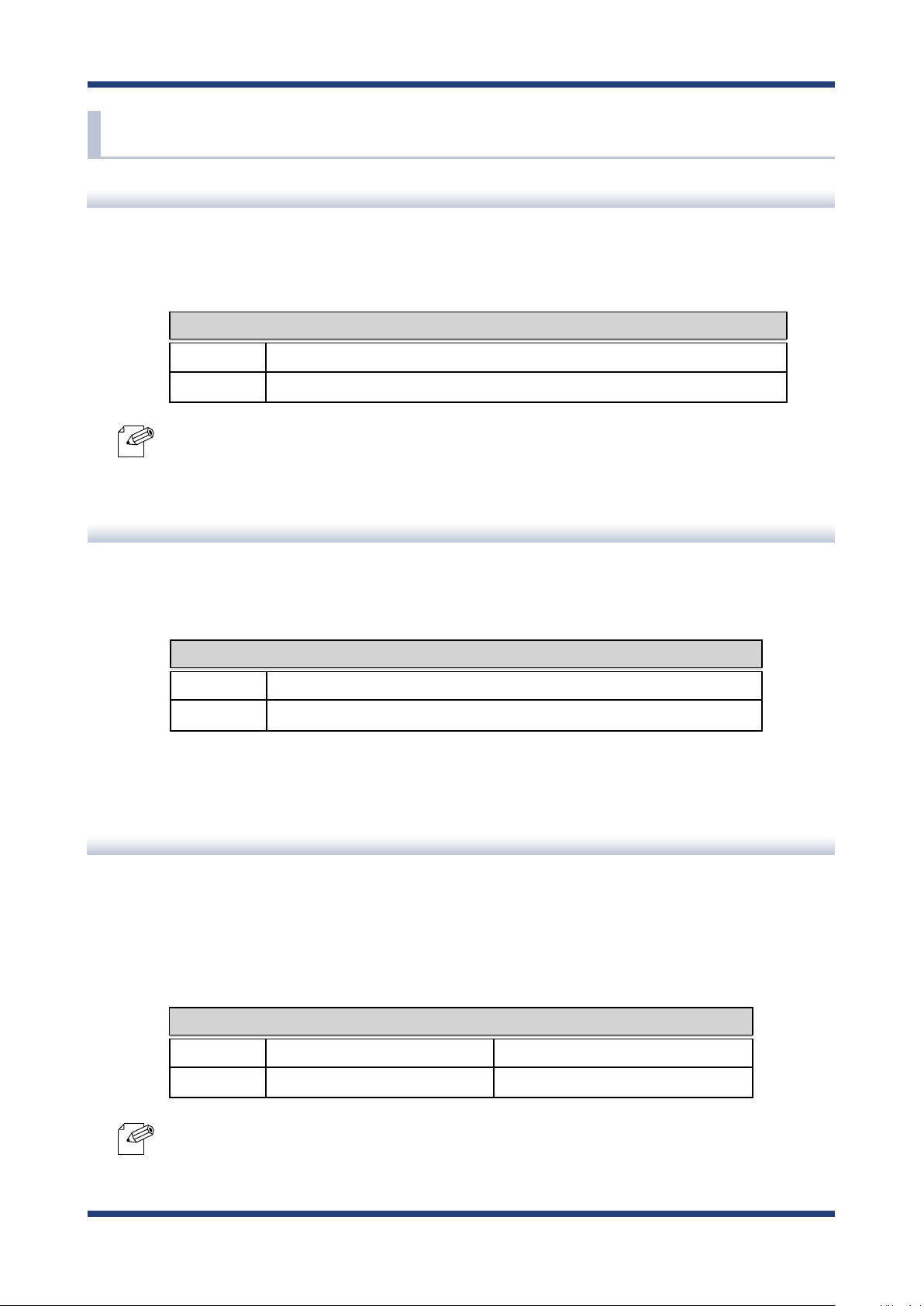
1-3. User Registration and Customer Services
User registration
To enable us to provide better services (support and repair), please perform the user
registration process from our website below:
URL
USA http://www.silexamerica.com/support/product-registration/
Japan http://www.silex.jp/register/
- For user registration, a serial number is required.
Note
Product Information
The services below are available from the Silex Technology website. For details, please visit
the Silex Technology website.
URL
USA http://www.silexamerica.com/
Japan http://www.silex.jp/
- Latest rmware download - Latest software download
- Latest manual download - Support information (FAQ)
Customer Support Center
Customer Support is available by e-mail or telephone for any problems that you may
encounter. If you cannot nd the relevant problem in this manual or on our website, or if
the corrective procedure does not resolve the problem, please contact Silex Technology
Customer Support.
Note
Contact Information
USA +1-801-748-1199 support@silexamerica.com
Japan +81-(0)774-98-3981 support@silex.jp
- Visit the Silex Technology website (http://www.silexamerica.com/) for the latest FAQ and product
information.
5
Page 12

NX-1 User's Guide
6
Page 13

2. About NX-1
2.
About NX-1
NX-1 is a wireless frame capture unit supporting IEEE 802.11 a/b/g/n. NX-1 enables you to
capture wireless LAN frames to survey a wireless environment before introducing wireless
LAN products, to monitor the operating status of NX-1, and to troubleshoot problems.
You can view the analysis results in the web page of NX-1.
2-1. Included Items
The following items are included with this package.
- NX-1
- AC adaptor
- Rubber feet
- Warranty booklet
- GPL notice sheet
(About distribution of GPL software source code)
- Website guide
7
Page 14

NX-1 User's Guide
2-2. Features
NX-1 has the following features.
NX-1 features the Operating Mode, which consists of the following four operation modes.
You can make use of them for various purposes concerning use of wireless LAN products,
such as an environment survey prior to introduction, operating status monitoring, and
troubleshooting.
Survey Mode
Measures use of specied wireless channels and reports the result in chart.
Monitoring Mode
Monitors the surrounding wireless environment regularly and reports the results in
chronological order in charts.
Spectrum Analyzer
Measures radio noise that aects wireless LAN and reports the results in chart.
Capture Mode
Captures wireless LAN frames of specied channels.
Standalone operation
NX-1 can be installed in a target wireless environment for standalone operation and
enables you to make a survey without technical knowledge about operating the unit.
Remote control via a wired LAN
In the environment which allows communication with NX-1 via a wired LAN, you can
remotely collect wireless LAN environment information and view the analysis results
through the Web page of NX-1.
External storages
You can store monitored/captured data in a USB storage connected to NX-1.
8
Page 15

2. About NX-1
Easy analysis function
Easy analysis function of NX-1 allows you to view collected wireless LAN environment
information in the Web page.
Print layout view
Wireless LAN information can be displayed in a printable format after it is collected in the
survey mode, monitoring mode or spectrum analyzer.
AMC Manager (non-free program) / AMC Finder (free program)
NX-1 supports the total management software, "AMC Manager" and "AMC Finder". The AMC
Manager provides the useful features as follows:
- Remote device control and monitoring
- Bulk conguration and rmware updates
Note
- For details on the "AMC Manager" and "AMC Finder", please visit our homepage.
9
Page 16

NX-1 User's Guide
2-3. Limitations and Precautions
The following limitations and precautions are applied to NX-1.
Limitations
- NX-1 does not support Short Guard Interval HT20 and cannot capture frames at the
corresponding transfer rates.
The communication at the corresponding rates is not reflected in the reports of the
Monitoring Mode and the Survey Mode.
- Depending on the performance of your USB storage, some frames can be missed and not
saved in the USB storage. Note that it is not guaranteed for all frames to be captured and
stored in all USB storages.
- The Capture Mode of NX-1 does not guarantee that all frames are captured correctly in
your wireless LAN environment.
Precautions
Do not perform the following actions during operation of the Operating Mode. The USB
storage may be damaged.
- Disconnect the USB storage from NX-1.
- Unplug the AC adaptor of NX-1 from an outlet (When receiving power over the Ethernet
(PoE), unplug the network cable).
Silex Technology will not be held liable for any damage to USB storages and/or data loss as
a result of use of NX-1.
10
Page 17
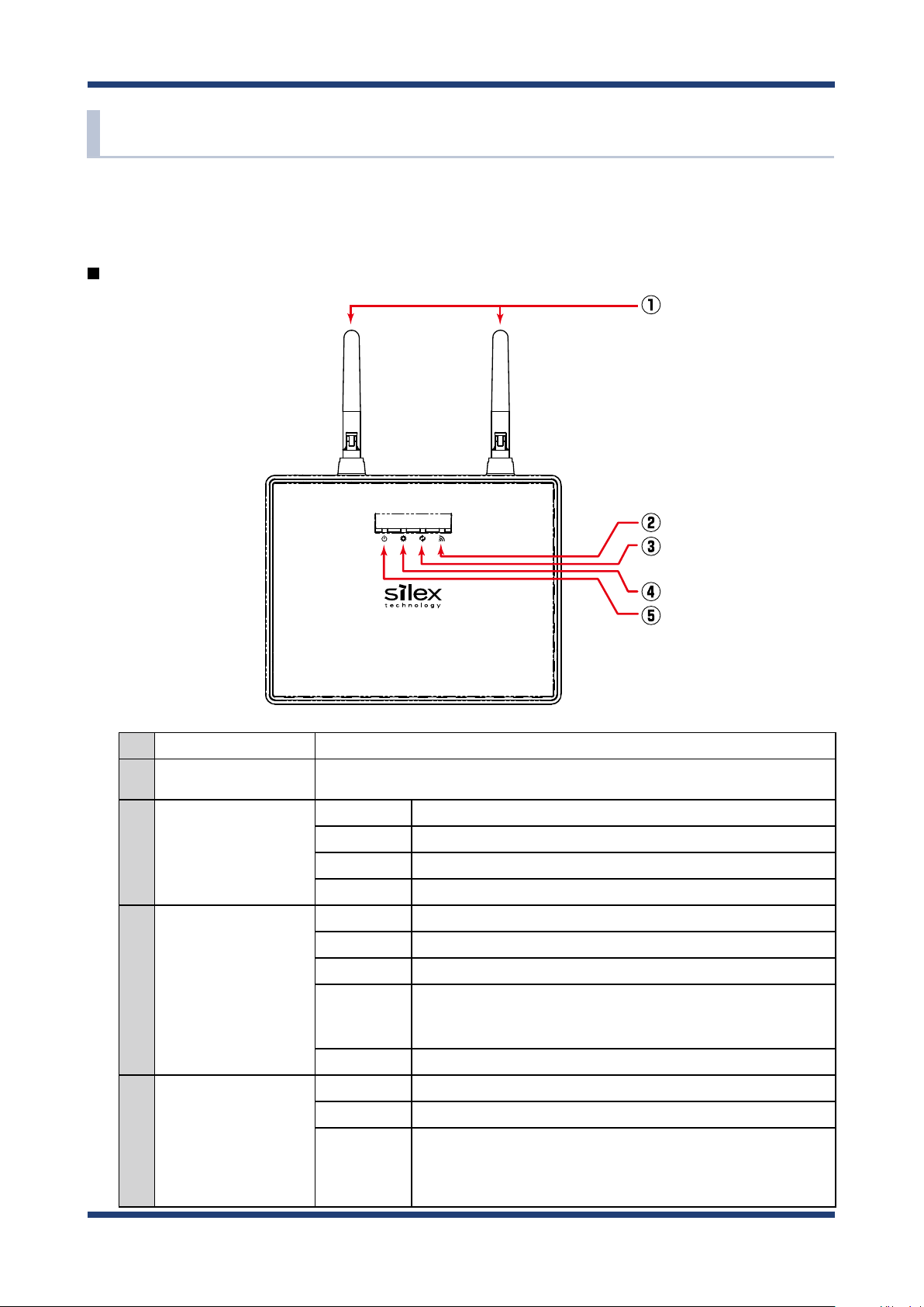
2-4. Parts and Functions
The parts name and functions are as follows:
Top
2. About NX-1
(1) Wireless LAN Antenna Antenna for receiving wireless LAN radio signals.
(2) WSTAT LED (Green)
BAND LED
(3)
(Green/Orange/Red)
SETTING LED
(4)
(Green/Orange/Red)
POWER LED
(5)
(Green/Orange/Red)
BLINK (Green) Turns on for 100 ms when wireless LAN frames are received followed by
turning o.
ON (Green) Storage writing speed is more than 20 Mbytes/sec.
ON (Orange) Storage writing speed is 10 to 20 Mbytes/sec.
ON (Red) Storage writing speed is less than 10 Mbytes/sec.
BLINK (Orange) Storage writing speed is being measured.
BLINK (Green) The Monitoring Mode is running (1 second interval).
BLINK (Orange) The Survey Mode is running (1 second interval).
BLINK (RED) The Capture Mode is running (1 second interval).
BLINK
ALTERNATELY
(Green/Red)
OFF No mode is running.
ON (Green) Ready
BLINK (Orange) Powering on (1 second interval)
BLINK (RED)
The Spectrum Analyzer mode is running (1 second interval).
USB storage writing error (500 ms intervals).
* A failure of writing data into a USB storage during an operation
results in an error.
11
Page 18
NX-1 User's Guide
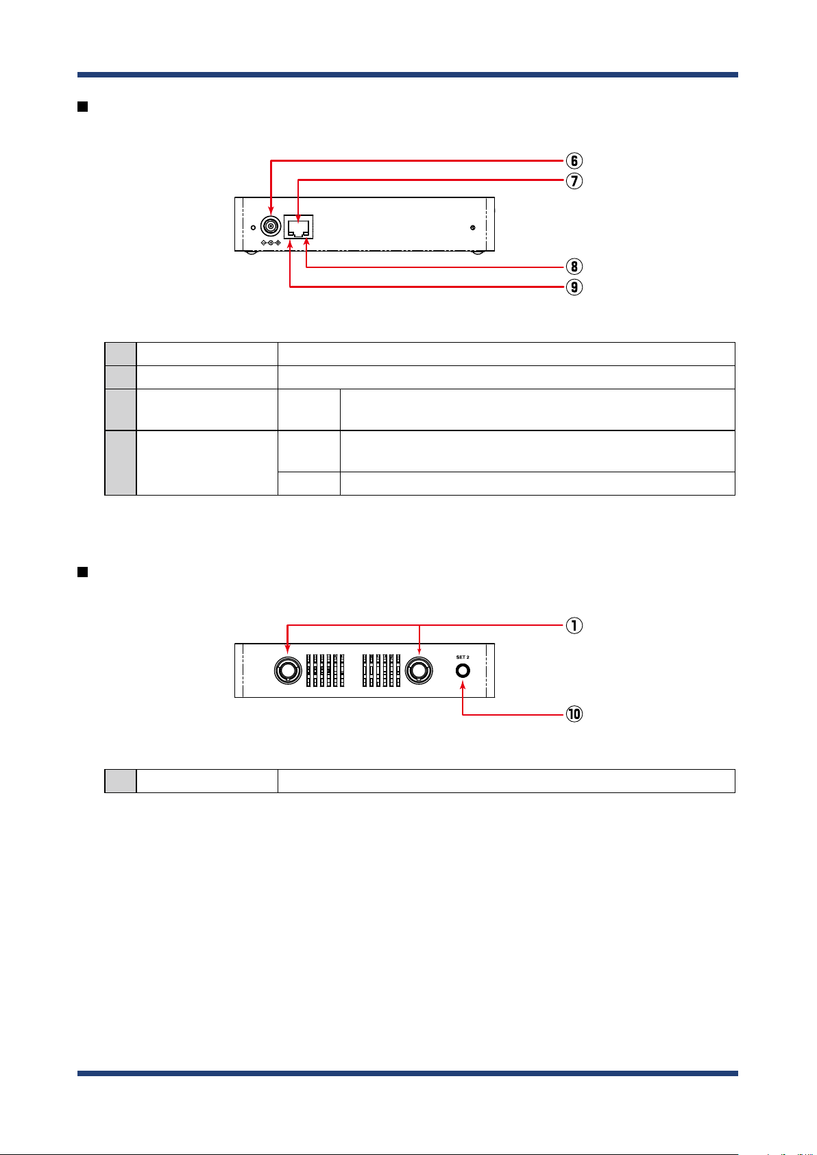
Front
DC12V IN LAN / PoE
(6) AC Connector Connect an AC adaptor.
(7) Network Port Connect a network cable.
(8) Status LED
(9) Link LED
BLINK
(Yellow)
ON
(Green)
OFF A wired LAN is disconnected.
Wired LAN packet receive status.
Turns on for 100 ms when packets are received followed by turning o.
A wired LAN is connected.
Back
(10)
Control Switch Starts or stops the pre-congured mode (the Monitoring Mode or the Capture Mode).
12
Page 19
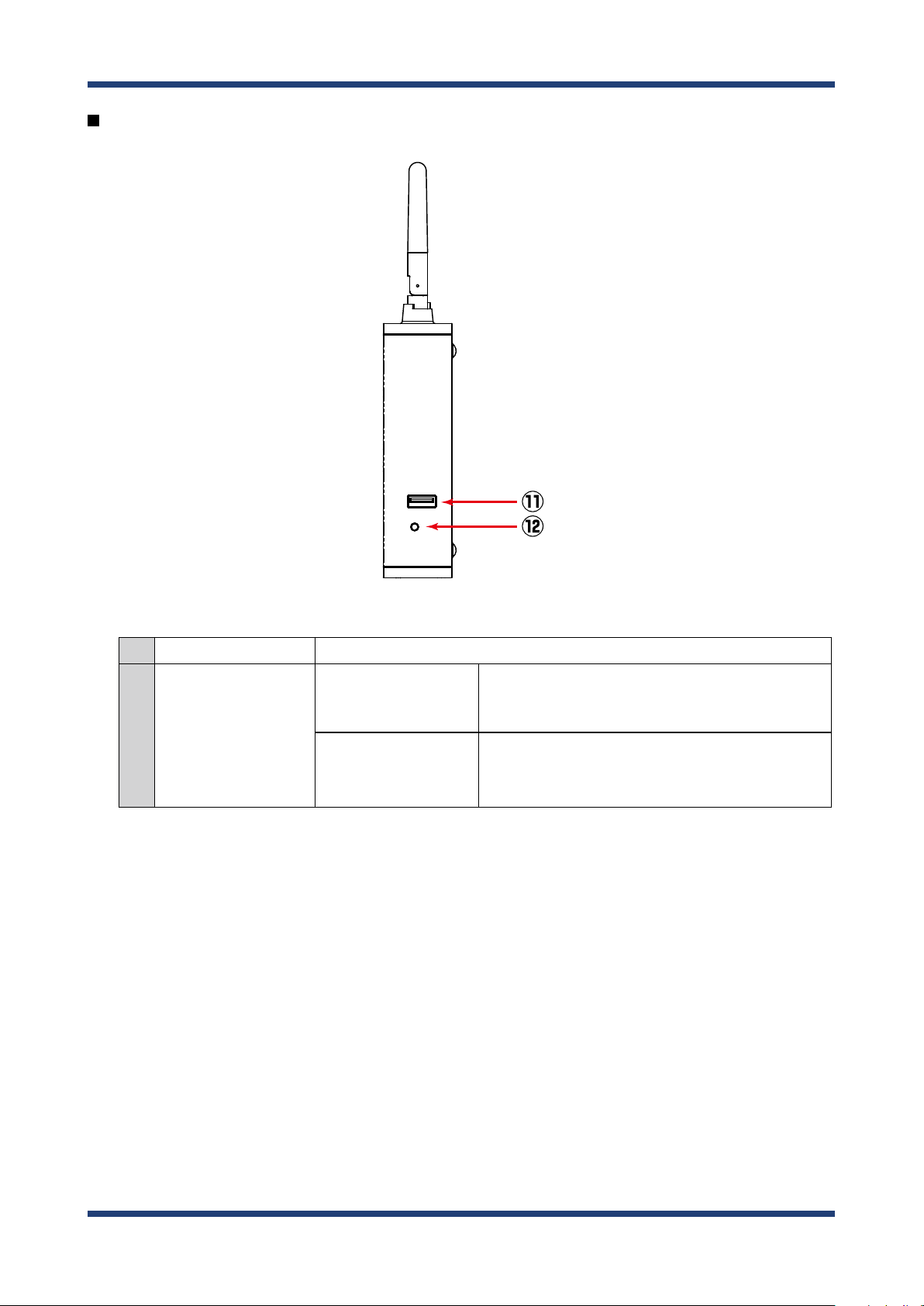
Right side
2. About NX-1
SET 1 USB
(11) USB Port Connect a USB storage.
Factory default
conguration
(12) Push switch
Unmount
Press when setting NX-1 to factory default conguration.
For details, see 5-1. Maintenance Feature - Factory
Default Conguration.
Press when unplugging the connected USB storage.
Press-and-hold for 1 second. When BAND LED on the top
of NX-1 turns o, you can remove the storage.
13
Page 20

NX-1 User's Guide
2-5. Hardware Specication
Operating Environment
Storage environment
Compliant standards
CPU 32bit RISC CPU
Memory
Wired network interface
Wireless network interface IEEE 802.11a/b/g/n
Antenna Non-directional antenna × 2
USB interface USB2.0 Hi-Speed port (A type) : 1 port
Push switch 2
LED
Temperature : 0 °C to +40 °C
Humidity : 20% to 80%RH (Non-condensing)
Temperature : -10 °C to +50 °C
Humidity : 20% to 90%RH (Non-condensing)
VCCI Class B
FCC Part15 SubPart B Class B
RAM
Flash ROM : 16 MByte
10BASE-T/100BASE-TX/1000BASE-T(Auto-sensing) : 1 port
Auto MDI/MDIX
Power over Ethernet (PoE)
Top
Network Port
: 64 MByte
For the Operating Mode: 1
For factory default conguration: 1
POWER LED (Green/Orange/Red)
SETTING LED (Green/Orange/Red)
BAND LED (Green/Orange/Red)
WSTAT LED (Green)
Status LED (Yellow)
Link LED (Green)
FCC Notice
This device complies with part 15 of the FCC Rules. Operation is subject to the following two conditions: (1) This device may not
cause harmful interference, and (2) this device must accept any interference received, including interference that may cause
undesired operation.
FCC CAUTION
Changes or modications not expressly approved by the party responsible for compliance could void the user's authority to
operate the equipment.
Federal Communication Interference Statement (United States only)
This equipment has been tested and found to comply with the limits for a Class B digital device, pursuant to part 15 of the
FCC Rules. These limits are designed to provide reasonable protection against harmful interference in a residential installation.
This equipment generates, uses and can radiate radio frequency energy and, if not installed and used in accordance with the
instructions, may cause harmful interference to radio communications. However, there is no guarantee that interference will not
occur in a particular installation. If this equipment does cause harmful interference to radio or television reception, which can be
determined by turning the equipment o and on, the user is encouraged to try to correct the interference by one or more of the
following measures:
- Reorient or relocate the receiving antenna.
- Increase the separation between the equipment and receiver.
- Connect the equipment into an outlet on a circuit dierent from that to which the receiver is connected.
- Consult the dealer or an experienced radio/TV technician for help.
14
Page 21
2-6. Software Specication
Supported protocols
Network layer ARP, IP, ICMP
2. About NX-1
TCP/IP
Transport layer TCP, UDP
Application layer TELNET, BOOTP, DHCP (Client), HTTP, NTP, JCP (Silex proprietary protocol),
Supported Web browsers
The recommended Web browsers are as follows:
Internet Explorer 11 or later
- Be sure to disable the Compatibility View feature.
TIP
Google Chrome 42.0 or later
For details, see A. Appendix - A-1. Notes on Web browsers.
15
Page 22

NX-1 User's Guide
2-7. OpenSSL License
This product includes software developed by the OpenSSL Project for use in the OpenSSL
Toolkit.
( http://www.openssl.org/ )
OpenSSL License
--------------/* ====================================================================
* Copyright (c) 1998-2005 The OpenSSL Project. All rights reserved.
*
* Redistribution and use in source and binary forms, with or without
* modication, are permitted provided that the following conditions
* are met:
*
* 1. Redistributions of source code must retain the above copyright
* notice, this list of conditions and the following disclaimer.
*
* 2. Redistributions in binary form must reproduce the above copyright
* notice, this list of conditions and the following disclaimer in
* the documentation and/or other materials provided with the
* distribution.
*
* 3. All advertising materials mentioning features or use of this
* software must display the following acknowledgment:
* "This product includes software developed by the OpenSSL Project
* for use in the OpenSSL Toolkit. (http://www.openssl.org/)"
*
* 4. The names "OpenSSL Toolkit" and "OpenSSL Project" must not be used to
* endorse or promote products derived from this software without
* prior written permission. For written permission, please contact
* openssl-core@openssl.org.
*
* 5. Products derived from this software may not be called "OpenSSL"
* nor may "OpenSSL" appear in their names without prior written
* permission of the OpenSSL Project.
*
* 6. Redistributions of any form whatsoever must retain the following
* acknowledgment:
* "This product includes software developed by the OpenSSL Project
* for use in the OpenSSL Toolkit (http://www.openssl.org/)"
*
16
Page 23

2. About NX-1
* THIS SOFTWARE IS PROVIDED BY THE OpenSSL PROJECT ``AS IS'' AND ANY
* EXPRESSED OR IMPLIED WARRANTIES, INCLUDING, BUT NOT LIMITED TO, THE
* IMPLIED WARRANTIES OF MERCHANTABILITY AND FITNESS FOR A PARTICULAR
* PURPOSE ARE DISCLAIMED. IN NO EVENT SHALL THE OpenSSL PROJECT OR
* ITS CONTRIBUTORS BE LIABLE FOR ANY DIRECT, INDIRECT, INCIDENTAL,
* SPECIAL, EXEMPLARY, OR CONSEQUENTIAL DAMAGES (INCLUDING, BUT
* NOT LIMITED TO, PROCUREMENT OF SUBSTITUTE GOODS OR SERVICES;
* LOSS OF USE, DATA, OR PROFITS; OR BUSINESS INTERRUPTION)
* HOWEVER CAUSED AND ON ANY THEORY OF LIABILITY, WHETHER IN CONTRACT,
* STRICT LIABILITY, OR TORT (INCLUDING NEGLIGENCE OR OTHERWISE)
* ARISING IN ANY WAY OUT OF THE USE OF THIS SOFTWARE, EVEN IF ADVISED
* OF THE POSSIBILITY OF SUCH DAMAGE.
* ====================================================================
*
* This product includes cryptographic software written by Eric Young
* (eay@cryptsoft.com). This product includes software written by Tim
* Hudson (tjh@cryptsoft.com).
*
*/
Original SSLeay License
----------------------/* Copyright (C) 1995-1998 Eric Young (eay@cryptsoft.com)
* All rights reserved.
*
* This package is an SSL implementation written
* by Eric Young (eay@cryptsoft.com).
* The implementation was written so as to conform with Netscapes SSL.
*
* This library is free for commercial and non-commercial use as long as
* the following conditions are aheared to. The following conditions
* apply to all code found in this distribution, be it the RC4, RSA,
* lhash, DES, etc., code; not just the SSL code. The SSL documentation
* included with this distribution is covered by the same copyright terms
* except that the holder is Tim Hudson (tjh@cryptsoft.com).
*
* Copyright remains Eric Young's, and as such any Copyright notices in
* the code are not to be removed.
* If this package is used in a product, Eric Young should be given attribution
* as the author of the parts of the library used.
* This can be in the form of a textual message at program startup or
* in documentation (online or textual) provided with the package.
*
17
Page 24

NX-1 User's Guide
* Redistribution and use in source and binary forms, with or without
* modication, are permitted provided that the following conditions
* are met:
* 1. Redistributions of source code must retain the copyright
* notice, this list of conditions and the following disclaimer.
* 2. Redistributions in binary form must reproduce the above copyright
* notice, this list of conditions and the following disclaimer in the
* documentation and/or other materials provided with the distribution.
* 3. All advertising materials mentioning features or use of this software
* must display the following acknowledgement:
* "This product includes cryptographic software written by
* Eric Young (eay@cryptsoft.com)"
* The word 'cryptographic' can be left out if the rouines from the library
* being used are not cryptographic related :-).
* 4. If you include any Windows specic code (or a derivative thereof) from
* the apps directory (application code) you must include an acknowledgement:
* "This product includes software written by Tim Hudson (tjh@cryptsoft.com)"
*
* THIS SOFTWARE IS PROVIDED BY ERIC YOUNG ``AS IS'' AND
* ANY EXPRESS OR IMPLIED WARRANTIES, INCLUDING, BUT NOT LIMITED TO, THE
* IMPLIED WARRANTIES OF MERCHANTABILITY AND FITNESS FOR A PARTICULAR PURPOSE
* ARE DISCLAIMED. IN NO EVENT SHALL THE AUTHOR OR CONTRIBUTORS BE LIABLE
* FOR ANY DIRECT, INDIRECT, INCIDENTAL, SPECIAL, EXEMPLARY, OR CONSEQUENTIAL
* DAMAGES (INCLUDING, BUT NOT LIMITED TO, PROCUREMENT OF SUBSTITUTE GOODS
* OR SERVICES; LOSS OF USE, DATA, OR PROFITS; OR BUSINESS INTERRUPTION)
* HOWEVER CAUSED AND ON ANY THEORY OF LIABILITY, WHETHER IN CONTRACT, STRICT
* LIABILITY, OR TORT (INCLUDING NEGLIGENCE OR OTHERWISE) ARISING IN ANY WAY
* OUT OF THE USE OF THIS SOFTWARE, EVEN IF ADVISED OF THE POSSIBILITY OF
* SUCH DAMAGE.
*
* The licence and distribution terms for any publically available version or
* derivative of this code cannot be changed. i.e. this code cannot simply be
* copied and put under another distribution licence
* [including the GNU Public Licence.]
*/
18
Page 25

3. Setup
3.
Setup
This chapter explains how to setup NX-1.
19
Page 26
NX-1 User's Guide
3-1.
Setup through the Web Page of NX-1
The following explains how to access and set up NX-1 from a Web browser on a PC.
- For information about supported Web browsers, see 2-6. Software speci cation.
TIP
- To use this setup method, you need to modify PC network settings temporarily.
Connecting NX-1 to a Network
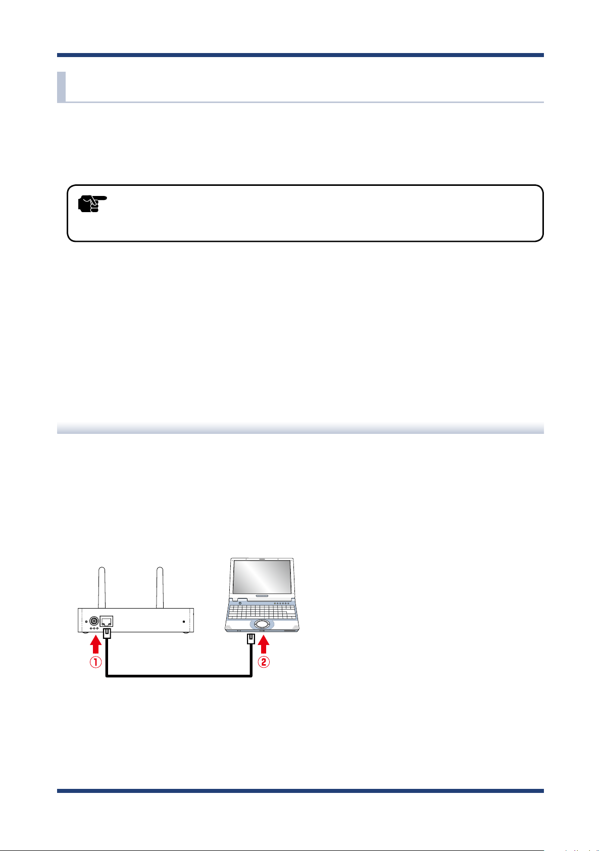
The following explains how to set up NX-1 by connecting it directly to your setup PC.
Connect NX-1 to your setup PC by using a network cable.
1.
PC
NX-1
DC12V IN LAN / PoE
Network Cable
20
Page 27
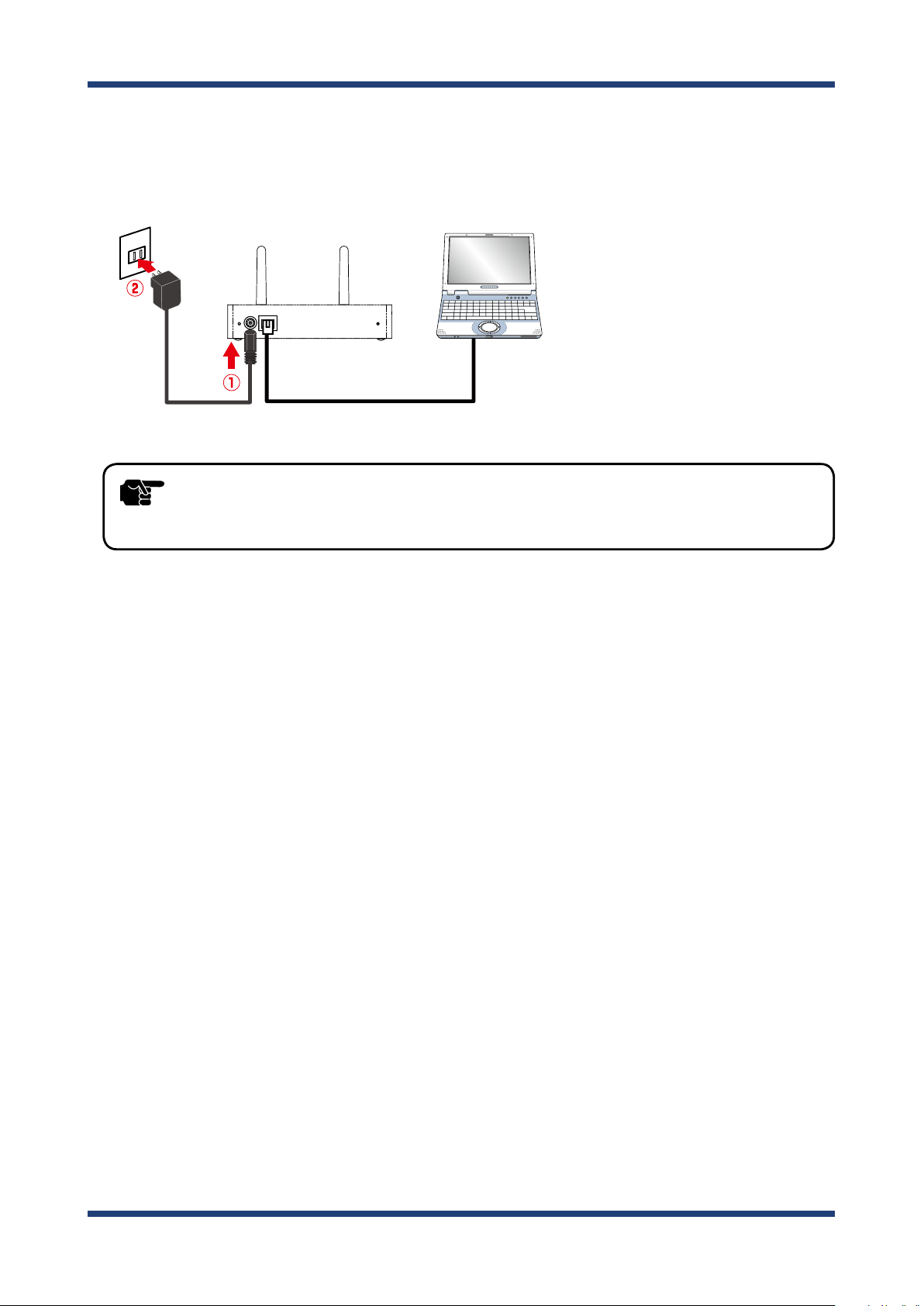
Connect the AC adaptor to NX-1 and plug in the AC adaptor into an outlet. NX-1 starts.
2.
When NX-1 is ready, the POWER LED (green) on the top of NX-1 stops blinking and
becomes ON.
PC
NX-1
DC12V IN LAN / PoE
3. Setup
AC adaptor
- Always use the AC adaptor bundled with NX-1. Other AC adaptors may cause failures.
TIP
Start your setup PC.
3.
Network Cable
21
Page 28

NX-1 User's Guide
Modifying PC Network Settings
You can use PCs to set up NX-1 and to view measurement results. The following explains
how to modify PC network settings so that you can access NX-1 from your PC.
The default IP address of NX-1 is 192.168.0.100 (Class C). Set up the IP address of your PC
so that it does not overlap the IP address of NX-1.
Example) Network settings
Set up the network settings of your PC as follows:
IP address : 192.168.0.123
Subnet mask : 255.255.255.0
Note
- To modify network settings on Windows 7
1. Click Start - Control Panel - Network and Internet - View network status and tasks. The Network
and Sharing center appears.
2. Click Local Area Connection. The Local Area Connection Status appears.
3. Click Properties. The Local Area Connection Properties appear.
4. Choose Internet Protocol (TCP/IP) and click Properties.
5. Set up IP address and Subnet mask. Enter Default gateway if necessary.
22
Page 29
Setting up NX-1
<To access the Web page of NX-1>
- The following screenshots show Internet Explorer 11 on Windows 7. The UI may dier depending on the
version of your operating system or that of your Web browser.
Note
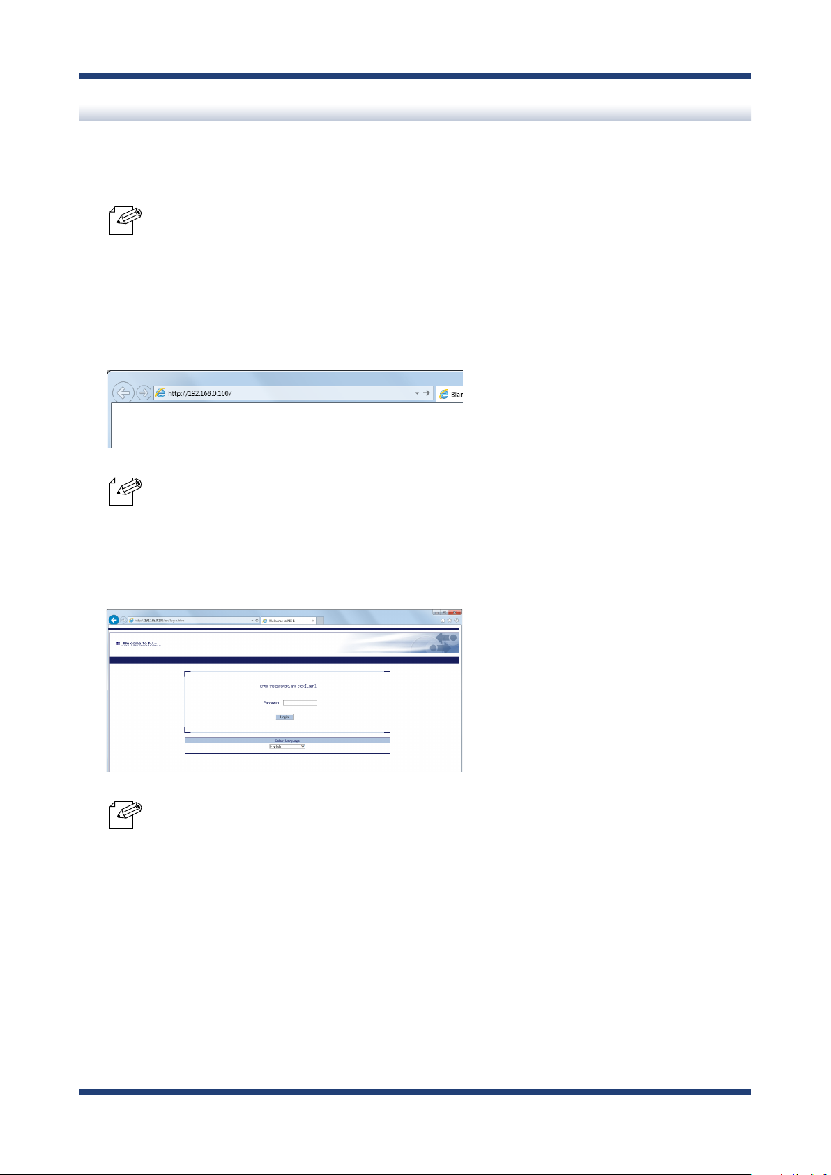
Start a Web browser on your setup PC and enter 192.168.0.100 in the address bar.
1.
3. Setup
- "192.168.0.100" is a default IP address congured to NX-1.
- When the IP address is changed during initial setup, enter the new IP address.
Note
The login page of NX-1 is displayed. Click Login.
2.
- No default password is set in NX-1.
- When the password has been changed during initial setup, enter the new password.
Note
- You cannot log in while another user is logging in from another device.
23
Page 30
NX-1 User's Guide
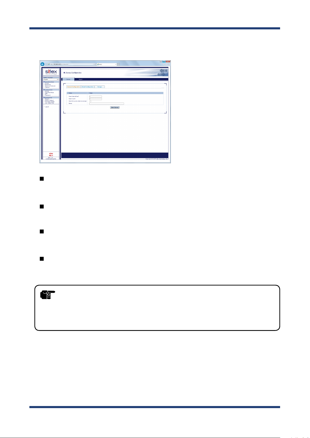
The Web page of NX-1 is displayed. From Conguration in the menu, select an item
3.
you want to set up.
Device Conguration
The Device Conguration allows you to set up TCP/IP of NX-1.
Operating Mode
The Operating Mode allows you to set up the Operating Mode default settings.
NTP
The NTP allows you to set up the NTP settings.
Password
The Password allows you to set up the password for NX-1.
- The Web page will automatically be logged out if no operations are made for a certain amount of time
TIP
after it is displayed. (The default is 30 minutes)
The auto-logout time can be changed from Conguration - Device.
To open a report page after log-out, re-login to NX-1.
24
Page 31

<Device Conguration>
The following explains how to set up TCP/IP of NX-1.
From Conguration in the Web page menu, click Device.
1.
3. Setup
The Device Conguration page is displayed. Enter each setting.
2.
- For information on the settings, see A. Appendix - A-2. List of All Settings.
Note
After entering the settings, click Submit in the lower right of the Web page.
3.
25
Page 32

NX-1 User's Guide
When the setup is completed, restart NX-1.
4.
- For information on how to restart NX-1, see 5-1. Maintenance Feature - Restarting in this manual.
- If you want to make a setup in another page, you do not have to restart NX-1 here. Restart it after you
Note
When the restart is completed, the login page of NX-1 is displayed.
5.
TIP
complete the setup.
- When the IP address have been changed to access an existing network, there are cases that you cannot
access the Web page of NX-1. In this case, to access the Web page, use a network cable and connect NX-1 to
a Ethernet hub of your network.
26
Page 33

3. Setup
<Operating Mode>
The Operating Mode Configuration allows you to set up the Operating Mode default
settings.
The settings entered in this page are displayed as the defaults in the page of the
corresponding Operating Mode.
From Conguration in the Web page menu, click Operating Mode.
1.
The Operating Mode Conguration page is displayed. Enter each setting.
2.
- For information on the settings, see A. Appendix - A-2. List of All Settings.
Note
27
Page 34

NX-1 User's Guide
After entering the settings, click Submit in the lower right of the Web page.
3.
When the setup is completed, restart NX-1.
4.
- For information on how to restart NX-1, see 5-1. Maintenance Feature - Restarting in this manual.
- If you want to make a setup in another page, you do not have to restart NX-1 here. Restart it after you
Note
When the restart is completed, the login page of NX-1 is displayed.
5.
TIP
complete the setup.
- When the IP address have been changed to access an existing network, there are cases that you cannot
access the Web page of NX-1. In this case, to access the Web page, use a network cable and connect NX-1 to
a Ethernet hub of your network.
28
Page 35

<NTP>
The NTP allows you to set up the NTP settings.
From Conguration in the Web page menu, click NTP.
1.
3. Setup
The NTP Conguration page is displayed. Enter each setting.
2.
- For information on the settings, see A. Appendix - A-2. List of All Settings.
Note
After entering the settings, click Submit in the lower right of the Web page.
3.
When the setup is completed, restart NX-1.
4.
Note
- For information on how to restart NX-1, see 5-1. Maintenance Feature - Restarting in this manual.
- If you want to make a setup in another page, you do not have to restart NX-1 here. Restart it after you
complete the setup.
29
Page 36

NX-1 User's Guide
When the restart is completed, the login page of NX-1 is displayed.
5.
- When the IP address have been changed to access an existing network, there are cases that you cannot
TIP
access the Web page of NX-1. In this case, to access the Web page, use a network cable and connect NX-1 to
a Ethernet hub of your network.
30
Page 37

<Password>
The Password allows you to set up the password for NX-1.
- No default password is set in NX-1.
TIP
From Conguration in the Web page menu, click Password.
1.
When using NX-1 with it connected to the public network, be sure to change the password.
3. Setup
The Password Conguration page is displayed. Enter a new password.
2.
- For information on the settings, see A. Appendix - A-2. List of All Settings.
Note
After entering the password, click Submit in the lower right of the Web page.
3.
31
Page 38

NX-1 User's Guide
When the setup is completed, restart NX-1.
4.
- For information on how to restart NX-1, see 5-1. Maintenance Feature - Restarting in this manual.
- If you want to make a setup in another page, you do not have to restart NX-1 here. Restart it after you
Note
When the restart is completed, the login page of NX-1 is displayed.
5.
TIP
complete the setup.
- When the IP address have been changed to access an existing network, there are cases that you cannot
access the Web page of NX-1. In this case, to access the Web page, use a network cable and connect NX-1 to
a Ethernet hub of your network.
32
Page 39

4. Using NX-1
4.
Using NX-1
This chapter explains how to collect wireless LAN environment information by using NX-1
and how to view analysis results of the easy analysis function of this product.
4-1.
NX-1 has two methods for collecting wireless LAN environment information.
- Clicking a start button on the Web page of NX-1
- Pressing the Control Switch on NX-1
You can view the analysis results of the collected information in the Web page of NX-1.
Survey Mode Yes No
Monitoring Mode Yes Yes
Spectrum Analyzer Yes No
Capture Mode Yes Yes
Yes: Supported No: Not supported
Collecting Wireless LAN Environment Information
Operating Mode Web page Control Switch
TIP
- For information about supported Web browsers, see 2-6. Software Specication.
33
Page 40

NX-1 User's Guide
Installing NX-1 in a Target Wireless LAN Environment to Collect Information
Install NX-1 in a target wireless LAN environment to collect information.
Installation location of NX-1 di ers depending on your target devices:
- When collecting information from multiple wireless LAN devices
Install NX-1 at the center surrounded by the target wireless LAN devices.
- When collecting information from a particular wireless LAN device
Install NX-1 near the target wireless LAN device
When collecting information through the Web page of NX-1
When viewing analysis results in the Web page
<When NX-1 is using the default IP address>
Connect NX-1 to a PC using a network cable.
1.
PC
NX-1
DC12V IN LAN / PoE
Network Cable
34
Page 41

4. Using NX-1
Connect the AC adaptor to NX-1 and plug in the AC adaptor into an outlet. NX-1
2.
starts.
PC
NX-1
DC12V IN LAN / PoE
AC adaptor
- Always use the AC adaptor bundled with NX-1. Other AC adaptors may cause failures.
Network Cable
TIP
After starting the PC, set up the network settings so that the PC can access
3.
NX-1.
- For how to set up PC network settings, see 3-1. Setup through the Web Page of NX-1 -
Modifying PC network settings in this manual.
Note
<When NX-1 is using a new IP address>
Connect NX-1 to your network environment.
35
Page 42

NX-1 User's Guide
When collecting information with the Control Switch of NX-1
Connect the AC adaptor to NX-1 and plug in the AC adaptor into an outlet. NX-1 starts.
NX-1
DC12V IN LAN / PoE
TIP
AC adaptor
- Always use the AC adaptor bundled with NX-1. Other AC adaptors may cause failures.
- The Survey Mode and the Spectrum Analyzer mode do not support information collection by means of
the Control Switch.
36
Page 43

4. Using NX-1
4-2. Using the Survey Mode
The Survey Mode scans specified channels sequentially and measures the wireless LAN
environment around NX-1. The measured data are analyzed by the analysis function of
NX-1 and the analysis results are displayed in chart in the Web page of NX-1.
<When to use the Survey Mode>
The Survey Mode is used for analysis of the status of currently used channels or for
selection of channels to use in initial introduction.
37
Page 44

NX-1 User's Guide
Running the Survey Mode through the Web Page
Start a Web browser and enter the IP address of NX-1 in the address bar.
1.
- By default, an IP address is set to NX-1 as "192.168.0.100".
- When the IP address has been changed during initial setup, enter the new IP address.
Note
The login page of NX-1 is displayed.
2.
Type the password set to NX-1 and click Login.
- No default password is set in NX-1.
When no changes are made in the password setting of NX-1, just click Login.
Note
The Survey Conguration page is displayed.
3.
This page is composed of
Storage tab. Click
- You cannot log in while another user is logged in from another device.
General Configuration
General Conguration
tab or
tab,
Detail Configuration
Detail Conguration
tab.
tab and
38
Detail CongurationGeneral Conguration
Page 45

4. Using NX-1
General Conguration
Scan Interval and Scan Count can be changed.
Detail Conguration
You can select target channels for each wireless band as well as Scan Interval and
Scan Count.
- The Survey Mode settings set in Operating Mode of Conguration in the Web page are displayed as the
defaults.
Note
- After changing the settings in General Configuration or Detail Configuration, the new settings are
displayed until you restart NX-1. After a restart, the defaults are displayed.
Storage
Data can be read or deleted from the storage.
To save the survey result to the storage, check the check box at Save the survey
4.
data to storage
- Up to 30 characters can be entered for Memo.
- Information entered to Memo will be displayed on data list of Storage tab.
Note
Click Start Survey to start the survey.
5.
.
Starting survey unchecks wireless band channels and changes the color of the check
boxes with the progress of the survey displayed.
Gray : Channels that are not surveyed
White : Channels that are going to be surveyed
Red : Channels that are being surveyed
Green : Channels that have been surveyed
39
Page 46

NX-1 User's Guide
- To stop survey, click Stop Survey in the center of the page.
Note
- When available disk space of USB storage is 4MB or lower, a warning message is displayed and the Start
TIP
Survey button is disabled. To deleted the measured data of NX-1, refer to 4-2. Using the Survey Mode,
4-4. Using the Spectrum Analyzer or 4-5. Using the Capture Mode for how to delete the data.
- Do not unplug the USB storage when the survey is in progress. The USB storage may be damaged.
When unplugging a USB storage, be sure to stop the survey process and unmount the storage beforehand.
For information on how to unmount, see the explanation of the Push Switch in 2.4 Parts and Functions.
- When survey is in progress, do not unplug the AC plug of NX-1 from an electrical outlet (when the power
is supplied by PoE, do not unplug the network cable). The USB storage may be damaged.
Completion of survey opens a report page showing the survey results in radar charts.
6.
- The report page will automatically be logged out if no operations are made for a certain amount of time
TIP
after it is displayed. (The default is 30 minutes)
The auto-logout time can be changed from Conguration - Device.
To open a report page after log-out, re-login to NX-1.
40
Page 47

4. Using NX-1
Viewing Survey Analysis Results
After completion of survey, the measurement analysis data are reported in charts in the
Web page.
Band Information
Based on the results of survey conducted by NX-1, the following band information is
displayed in radar charts or bar charts. Chart scales of both radar charts and bar charts
can be adjusted.
Print Layout
Opens a printable format page.
Band Occupy Ratio
Displays band occupy ratio for specied channels.
Device Count
Displays the number of access points and stations that are confirmed to be in
operation.
Frame Status
Displays received correct frames/error frames/retry frames both in percentage and in
numerical values.
41
Page 48

NX-1 User's Guide
Device Information
Displays information on wireless devices that are in operation in each channel based on
the survey results conducted by NX-1.
Print Layout
Opens a printable format page.
Access Point Information
Displays information on access points in operation.
Station Information
Displays information on stations that have communicated with access points during
survey.
42
Page 49

Band Information - Band Occupy Ratio
Displays wireless band occupy ratio for specied channels in percentage.
4. Using NX-1
Band Occupy Ratio
Displays wireless band occupy ratio for specied channels in radar charts or bar charts.
Chart
Allows you to select how to display wireless band occupy ratio.
Radar: Displays wireless band occupy ratio in radar charts.
Bar: Displays wireless band occupy ratio in bar charts.
Scale
Allows you to select scales of displayed charts.
5/10/25/50/100 (Unit: %)
Radar chart Bar chart
43
Page 50

NX-1 User's Guide
Band Information - Device Count
Displays the total number of access points and that of stations connected to the access
points for specied channels.
Radar chart Bar chart
Access Point
Checking this displays the total number of access points for specied channels in radar
charts or bar charts.
Station
Checking this displays the total number of stations connected to access points for
specied channels.
- The number of stations is counted up when a frame sent from a station to an access point is detected during
survey.
Note
- Stations that do not communicate during survey are not detected or counted.
Total
Checking this displays the total number of access points and stations for specified
channels.
44
Page 51

Chart
Allows you to select how to display wireless band occupy ratio.
Radar : Displays the number of devices in radar charts.
Bar : Displays the number of devices in bar charts.
Scale
Allows you to select scales of displayed charts.
10/25/50/100/250/500 (Unit: the number of devices)
4. Using NX-1
45
Page 52

NX-1 User's Guide
Band Information - Frame Status
Displays wireless band occupy ratio for specied channels in percentage.
Correct
Displays the number of received correct wireless frames in percentage or numerical
values in radar charts or bar charts.
Error
Displays the number of received error wireless frames in percentage or numerical values
in radar charts or bar charts.
Retry
Displays the number of received retry wireless frames in percentage or numerical values
in radar charts or bar charts.
Radar chart Bar chart
46
Page 53

Chart
Allows you to select how to display the frames previously mentioned.
Radar : Displays the previously mentioned frames in radar charts.
Bar : Displays the previously mentioned frames in bar charts.
Ratio : Displays the number of received frames in percentage.
Count : Displays the number of received frames in numerical value.
Scale
Allows you to select scales of displayed charts.
Ratio : 5/10/25/50/100
Count : 10/100/1000/10000
4. Using NX-1
47
Page 54

NX-1 User's Guide
Survey Conguration - Device Information
Displays information on the operating access points and the operating stations for each
channel.
Frequency bands and channels
You can select frequency bands and channels to display.
Band Channel
2.4GHz
5GHz(W52)
5GHz(W53)
CH1-CH13
CH36/CH40/CH44/CH48
CH52/CH56/CH60/CH64
CH100/CH104/CH108/CH112/CH116/CH120
5GHz(W56)
CH124/CH128/CH132/CH136/CH140
5GHz(W58)
All Channel
CH149/CH153/CH157/CH161/CH165
All channels mentioned above
48
Page 55

Access Point Information
Displays the following information on access points.
Wireless device information Remarks
MAC Address (BSSID) Displays a MAC address (BSSID) of an access point.
ESSID(SSID) Displays an ESSID (SSID) of an access point.
Displays the wireless signal strength of an access point in dbm.
Green: ≥ -60 (dBm)
4. Using NX-1
Wireless signal strength
The number of connected
stations
Encryption Displays a key mark when the access point is encrypted.
Operation mode Displays [n] when IEEE802.11n is used.
Yellow: < -60 (dBm)
Red: < -80 (dBm)
Displays the number of stations connected to the access point.
Station information
Clicking the arrow on the left when there is a connected station displays the station.
Wireless device information Remarks
MAC Address Displays the MAC address of the station.
Wireless signal strength Displays the wireless signal strength of the station.
49
Page 56

NX-1 User's Guide
Survey Conguration - List of Data on Storage
If the Storage tab is clicked, the survey result is displayed that is saved in the storage.
Reading the survey results
Select the data to read from a list and click Display.
1.
50
Page 57

The selected survey result is displayed.
2.
4. Using NX-1
Deleting the survey results
Select the data to delete from a list and click Delete.
1.
51
Page 58

NX-1 User's Guide
Click OK to delete.
2.
When the data is deleted, a list of data is displayed again.
3.
52
Page 59

4. Using NX-1
Displaying Print Layout
If the Print Layout button is clicked in the report page, a printable format page is
displayed.
- Print quality will dier depending on the Web browser you use.
TIP
Click the Print Layout button in the report page.
1.
Click the information to display in the printable format page.
2.
53
Page 60

NX-1 User's Guide
Band Information
Shows the graphs of band information in a printable format page.
Device Information
Shows the device information in a printable format page.
All Information
Shows the band information and device information in a printable format page.
Printable format page is displayed.
3.
54
Page 61

4. Using NX-1
4-3. Using the Monitoring Mode
The Monitoring Mode allows you to scan specied channels regularly and to take long term
measurements of surrounding wireless environment.
Measured data are stored in a USB storage connected to NX-1. The 24-hour averages of the
measurement items are displayed as statistics information in chart format in the Web page
of NX-1.
<When to use the Monitoring Mode>
Use this function when monitoring statuses of currently used channels or when analyzing
causes of communication troubles that occasionally occur.
55
Page 62

NX-1 User's Guide
Running the Monitoring Mode through the Web Page
The following explains how to perform monitoring operations using the Monitoring
Conguration page of NX-1.
Plug in a USB storage into a USB port on the right side of NX-1.
1.
Start a Web browser and enter the IP address of NX-1 in the address bar.
2.
- By default, an IP address is set to NX-1 as "192.168.0.100".
- When the IP address has been changed during initial setup, enter the new IP address.
Note
The login page of NX-1 is displayed.
3.
Type the password set to NX-1 and click Login.
- No default password is set in NX-1.
When no changes are made in the password setting of NX-1, just click Login.
Note
The Survey Conguration page is displayed.
4.
From Operating Mode in the Web page menu, click Monitoring.
- You cannot log in while another user is logging in from another device.
56
Page 63

4. Using NX-1
The Monitoring Conguration page is displayed.
5.
The Monitoring Conguration page has the General Conguration tab and the Detail
Conguration tab.
Click Start Monitoring in one of the tabs.
General Conguration Detail Conguration
General Conguration
You can change only Monitoring Interval.
Detail Conguration
You can change Radio band channels to monitor and Monitoring Interval.
- Monitoring settings set up in Operating Mode under Conguration in the Web page are displayed as the
defaults.
Note
Monitoring starts. To stop the monitoring operation, click Stop Monitoring.
6.
- After changing the settings in General Configuration or Detail Configuration, the new settings are
displayed until you restart NX-1. After a restart, the defaults are displayed.
Note
- Monitoring data are stored in a storage on a daily basis.
- A failure of writing data into a USB storage during monitoring operation results in an error.
57
Page 64

NX-1 User's Guide
- Do not unplug a USB storage during monitoring operation. The USB storage may be damaged. When
TIP
unplugging a USB storage, be sure to stop monitoring operation and unmount the storage beforehand
For information on how to unmount, see the explanation of the Push Switch in 2.4 Parts and Functions.
- Do not unplug the AC adaptor of NX-1 from an outlet during monitoring operation (When the power is
supplied by PoE, do not unplug the network cable.). The USB storage may be damaged.
58
Page 65

4. Using NX-1
Using the Control Switch to Run the Monitoring Mode
The following explains how to perform monitoring operations with the Control Switch on
the back of NX-1.
- To perform monitoring operation with the Control Switch, you need to assign Monitoring to the switch.
TIP
To start monitoring operation
1.
2.
From Operating Mode - Push Switch Conguration in the Web page of NX-1, you can set up the Control
Switch.
Plug in a USB storage into a USB port on the right side of NX-1.
Turn on NX-1.
Press-and-holding the Control Switch on the back of NX-1 for one second or more
3.
causes the WSTAT LED (green) and SETTING LED (green) on the top side to blink,
and a monitoring operation starts.
After conrming the start of monitoring operation, release the Control Switch.
- Monitoring data are stored in a storage on a daily basis.
- The status of the Capture Conguration page is Monitoring during monitoring operation.
Note
- A failure of writing data into a USB storage during monitoring operation results in an error.
- Do not unplug a USB storage during monitoring operation. The USB storage may be damaged. When
TIP
unplugging a USB storage, be sure to stop monitoring operation and unmount the storage beforehand
For information on how to unmount, see the explanation of the Push Switch in 2.4 Parts and Functions.
- Do not unplug the AC adaptor of NX-1 from an outlet during monitoring operation (When the power is
supplied by PoE, do not unplug the network cable.). The USB storage may be damaged.
59
Page 66

NX-1 User's Guide
To stop monitoring operation
Press-and-holding the Control Switch on the back of NX-1 for one second or more turns
o the WSTATLED (green) and SETTING LED (green) on the top side, and the monitoring
operation stops.
After conrming the stop of monitoring operation, release the Control Switch.
- You can also stop monitoring as follows: Log in the Web page of NX-1. From Operating Mode, choose
Monitoring. In Monitoring Conguration, click Stop Monitoring.
Note
60
Page 67

4. Using NX-1
Viewing Monitoring Results
After completion of the Monitoring Mode, the monitoring results are analyzed and the
report of the data is displayed in chart format in the Web page.
Print Layout
Opens a printable format page.
Bands and Channels
Allows you to select bands and channels to display.
Band Channel
2.4GHz
5GHz(W52)
5GHz(W53)
CH1-CH13
CH36/CH40/CH44/CH48
CH52/CH56/CH60/CH64
CH100/CH104/CH108/CH112/CH116/CH120
5GHz(W56)
CH124/CH128/CH132/CH136/CH140
5GHZ(W58)
All Channel
CH149/CH153/CH157/CH161/CH165
All channels mentioned above
61
Page 68

NX-1 User's Guide
Band Occupy Ratio
Shows the usage rate of a specied wireless band on a daily basis.
The vertical axis is the usage rate and the horizontal axis is time.
Device Count
Shows the number of access points communicating in a specied wireless band and the
number of connected stations on a daily basis.
Frame Status
Shows correct frames, error frames, and retry frames contained in received frames of a
specied band in percentage or numerical value on a daily basis.
Frame Type
Shows management frames, control frames, and data frames contained in received
correct frames of a specied band in percentage or numerical value on a daily basis.
- The report page will automatically be logged out if no operations are made for a certain amount of time
TIP
after it is displayed. (The default is 30 minutes)
The auto-logout time can be changed from Conguration - Device.
To open a report page after log-out, re-login to NX-1.
62
Page 69

4. Using NX-1
Monitoring Conguration - Band Occupy Ratio
After completion of the Monitoring Mode, the monitoring results are analyzed and the
usage rate of a wireless band is displayed in percentage in chart format in the Web page.
Wireless Band
Displays the usage rate of wireless band in percentage in chronological order.
Average Band Occupy
Displays the average band occupy ratio calculated from the monitoring results.
Scale
Allows you to select scales of displayed charts.
10/25/50/100 (Unit: %)
63
Page 70

NX-1 User's Guide
Monitoring Conguration - Device Count
After completion of the Monitoring Mode, the monitoring results are analyzed and the
total number of access points and that of stations are displayed in chart format in the Web
page.
Access Point
Checking this displays the total number of access points in green in chronological order.
Station
Checking this displays the total number of stations connected to access points in red in
chronological order.
- The number of stations is counted up when a frame sent from a station to an access point is detected during
survey.
Note
- Stations that do not communicate during survey are not detected or counted.
Total
Checking this displays the total number of access points and stations in blue in
chronological order.
Average Device
Displays the average number of devices in operation.
Scale
Allows you to change the chart scale.
10/25/50/100/250/500 (Unit: the number of devices)
64
Page 71

4. Using NX-1
Monitoring Conguration - Frame Status
After completion of the Monitoring Mode, the monitoring results are analyzed and correct
frames, error frames, and retry frames are displayed in percentage and numerical value in
chart format in the Web page.
Correct
Checking this displays correct frames (frames with no error) of received frames in
percentage or numerical value in green in chronological order.
Error
Checking this displays error frames of received frames in percentage or numerical value
in green in chronological order.
Retry
Checking this displays retry frames of received frames in percentage or numerical value
in green in chronological order.
Total Frame
Displays the total number of frames received during monitoring operation.
Chart
Allows you to select how to display the frames previously mentioned.
Ratio : Displays the number of received frames in percentage.
Count : Displays the number of received frames in numerical value.
Scale
Allows you to change the chart scale.
- Ratio : 10/25/50/100 (Unit: %)
- Count : 10/100/1000/10000
65
Page 72

NX-1 User's Guide
Monitoring Conguration - Frame Type
After completion of the Monitoring Mode, the monitoring results are analyzed and
management frames, control frames, and data frames are displayed in percentage and
numerical value in chart format in the Web page.
Management
Displays management frames contained in received correct frames in percentage or
numerical value in green.
Control
Displays control frames contained in received correct frames in percentage or numerical
value in red.
Data
Displays control frames contained in received correct frames in percentage or numerical
value in blue.
Total Correct Frame
Displays the total number of correct frames received during monitoring operation.
Chart
Allows you to select how to display the frames previously mentioned.
Ratio : Displays the number of received frames in percentage.
Count : Displays the number of received frames in numerical value.
Scale
Allows you to change the chart scale.
- Ratio : 10/25/50/100 (Unit: %)
- Count : 10/100/1000/10000
66
Page 73

Changing Display Date
You can select obtained monitoring data to display.
4. Using NX-1
Putting the cursor in the date entry eld in the upper left of the window followed by
1.
clicking there opens a calendar.
Dates of the calendar that have their corresponding monitoring data are displayed in
green boldface.
Select a date to display.
2.
Click Change Disp Date.
3.
The report of the result for the selected date is displayed.
67
Page 74

NX-1 User's Guide
Changing Display Time
You can rescale the charts.
To rescale the charts with the slider displayed on the top of the tab.
Put the cursor at the start point (green) on the left and/or at the end point (orange)
1.
on the right of the slider, then slide them and specify the time to display.
Click Change Disp Time.
2.
All charts are rescaled according to the specied time.
3.
68
Page 75

To rescale the charts by using the mouse cursor in charts
In a chart to rescale, put the mouse cursor at a point of the display start time, then
1.
click and drag the cursor to the right. When reaching the display end time, release
the cursor.
4. Using NX-1
The chart you adjusted is rescaled according to the specied time.
2.
69
Page 76

NX-1 User's Guide
Displaying Print Layout
If the Print Layout button is clicked on the report page, the printable format page is
displayed.
- Print quality will di er depending on the Web browser you use.
TIP
Click the Print Layout button in the report page.
1.
Printable format page is displayed.
2.
70
Page 77

4. Using NX-1
4-4. Using the Spectrum Analyzer
The Spectrum Analyzer mode measures wireless signal conditions of specied frequency
bands.
Measured data are stored in a USB storage connected to NX-1. The spectrogram and
spectral density of the data are displayed in chart format in the Web page of NX-1.
<When to use the Spectrum Analyzer>
Use this function when monitoring statuses of currently used channels or when analyzing
causes of communication troubles that occasionally occur.
71
Page 78

NX-1 User's Guide
Running the Spectrum Analyzer through the Web Page
Plug in a USB storage into a USB port on the right side of NX-1.
1.
Start a Web browser and enter the IP address of NX-1 in the address bar.
2.
- By default, an IP address is set to NX-1 as "192.168.0.100".
- When the IP address has been changed during initial setup, enter the new IP address.
Note
The login page of NX-1 is displayed.
3.
Type the password set to NX-1 and click Login.
- No default password is set in NX-1.
When no changes are made in the password setting of NX-1, just click Login.
Note
The Survey Conguration page is displayed.
4.
From Operating Mode in the Web page menu, click Spectrum Analyzer.
- You cannot log in while another user is logged in from another device.
72
Page 79

The Spectrum Analyzer Conguration page is displayed.
5.
Set up measurement settings, then click Start.
- The Spectrum Analyzer settings set in Operating Mode under Configuration of the Web page are
displayed as the defaults.
Note
The Spectrum Analyzer starts.
6
- After changing the settings, the new settings are displayed until you restart NX-1. After a restart, the
defaults are displayed.
4. Using NX-1
TIP
- Do not unplug a USB storage when the Spectrum Analyzer is in operation. The USB storage may be
damaged. When unplugging a USB storage, be sure to stop the Spectrum Analyzer and unmount the
storage beforehand. For information on how to unmount, see the explanation of the Push Switch in 2.4
Parts and Functions.
- Do not unplug the AC adaptor of NX-1 from an outlet when the Spectrum Analyzer is in operation (When
the power is supplied by PoE, do not unplug the network cable). The USB storage may be damaged.
73
Page 80

NX-1 User's Guide
Completion of a Spectrum Analyzer operation opens a report page showing the
7.
measurement results.
TIP
- The report page will automatically be logged out if no operations are made for a certain amount of time
after it is displayed. (The default is 30 minutes)
The auto-logout time can be changed from Conguration - Device.
To open a report page after log-out, re-login to NX-1.
74
Page 81

4. Using NX-1
Viewing Measurement Results
The spectrogram and spectral density of measured data are displayed in the Web page.
Print Layout
Opens a printable format page.
Frequency Bands
Allows you to select frequency bands to display from 2.4GHz, 5GHz (W52/W53), 5GHz (W56),
or 5GHz (W58).
Spectrogram
Displays frequency, time, and signal strength on x, y, and z axis respectively in a three-
dimensional chart.
Spectral Density
Displays frequency, signal strength, and z (appearance ratio) on x, y, and z axis
respectively in a three-dimensional chart.
File Name
Displays the names of stored data les.
Delete button
Deletes the stored data.
75
Page 82

NX-1 User's Guide
Spectrum Analyzer - Spectrogram
Wireless signal conditions of each frequency band during measurement time are displayed
in a three-dimensional chart.
Spectrogram
After measurement, displays frequency, time, and signal strength on x, y, and z axis
respectively in a three-dimensional chart.
Using the sidebar on the right allows you to narrow the range of signal strength to display.
The past report can be displayed by clicking one from the drop-down list.
76
Page 83

4. Using NX-1
Spectrum Analyzer - Spectral Density
Signal strength densities of each frequency band detected during measurement are
displayed in percentage.
Spectral Density
After measurement, displays x (frequency), y (signal strength), and z (density, or
appearance ratio) in a three-dimensional chart.
Using the sidebar on the right allows you to narrow the range of signal strength density
to display.
The past report can be displayed by clicking one from the drop-down list.
77
Page 84

NX-1 User's Guide
Deleting Measured Data
The measured data of USB storage can be deleted on the report page.
Go to the Report page of Spectrum Analyzer.
1.
Select the data to delete from the drop-down list and click Delete.
2.
Click OK to delete.
3.
When the data is deleted, the Report page is displayed again.
4.
78
Page 85

4. Using NX-1
Displaying Print Layout
If the Print Layout button is clicked on the report page, the printable format page is
displayed.
- Print quality will dier depending on the Web browser you use.
TIP
Click the Print Layout button in the report page.
1.
Printable format page is displayed.
2.
79
Page 86

NX-1 User's Guide
4-5. Using the Capture Mode
The Capture Mode allows you to capture wireless LAN frames of specied channels.
Captured data are saved in PCAP les and stored in a USB storage connected to NX-1.
<When to use the Capture Mode>
When a communication trouble occurs in wireless LAN environment, this mode allows you
to capture wireless frames and analyze them for errors, helping you to troubleshoot.
Analyzing wireless frames requires you to have a technical knowledge of wireless LAN.
80
Page 87

Running the Capture Mode through the Web Page
Plug in a USB storage into a USB port on the right side of NX-1.
1.
Start a Web browser and enter the IP address of NX-1 in the address bar.
2.
- By default, an IP address is set to NX-1 as "192.168.0.100".
- When the IP address has been changed during initial setup, enter the new IP address.
Note
The login page of NX-1 is displayed.
3.
Type the password set to NX-1 and click Login.
4. Using NX-1
- No default password is set in NX-1.
When no changes are made in the password setting of NX-1, just click Login.
Note
The Survey Conguration page is displayed.
4.
From Operating Mode in the Web page menu, click Capture.
- You cannot log in while another user is logged in from another device.
81
Page 88

NX-1 User's Guide
The Capture Conguration page is displayed.
5.
Set up capture settings, then click Start capture.
- Capture settings set in Operating Mode of Conguration in the Web page are displayed as the defaults.
- After changing the settings, the new settings are displayed until you restart NX-1. After a restart, the
Note
Capture starts.
6.
defaults are displayed.
To stop the capture, click Stop capture.
Note
TIP
- A failure of writing data into a USB storage during capture results in an error.
- Do not unplug a USB storage during capture. The USB storage may be damaged. When unplugging a
USB storage, be sure to stop capture and unmount the storage beforehand For information on how to
unmount, see the explanation of the Push Switch in 2.4 Parts and Functions.
- Do not unplug the AC adaptor of NX-1 from an outlet during capture (When the power is supplied by
PoE, do not unplug the network cable). The USB storage may be damaged.
82
Page 89

Using the Control Switch to Run the Capture Mode
The Control Switch on the back of NX-1 allows you to start or stop capture.
- To perform capture operation with the Control Switch, you need to assign Capture to the switch. From
TIP
To start capture
1.
2.
Operating Mode - Push Switch Conguration in the Web page of NX-1, you can set up the Control Switch.
Plug in a USB storage into a USB port on the right side of NX-1.
Turn on NX-1.
4. Using NX-1
Press-and-holding the Control Switch (SET2) on the back of NX-1 for one second or
3.
more causes the WSTAT LED (green) and SETTING LED (red) on the top side to blink,
and a capture operation starts.
After conrming the start of capture, release the Control Switch.
- The status of the Capture Conguration page is Capturing frame during capture operation.
- A failure of writing data into a USB storage during capture results in an error.
Note
- Do not unplug a USB storage during capture. The USB storage may be damaged. When unplugging a
TIP
USB storage, be sure to stop capture and unmount the storage beforehand for information on how to
unmount, see the explanation of the Push Switch in 2.4 Parts and Functions.
- Do not unplug the AC adaptor of NX-1 from an outlet during capture (When the power is supplied by
PoE, do not unplug the network cable). The USB storage may be damaged.
83
Page 90

NX-1 User's Guide
To stop capture
Press-and-holding the Control Switch (SET2) on the back of NX-1 for one second or
more turns o the WSTAT LED (green) and SETTING LED (red) on the top side, and the
capture operation stops.
After conrming the stop of capture, release the Control Switch.
- You can also stop capture as follows: Log in the Web page of NX-1. From Operating Mode, choose Capture.
In Capture Conguration, click Stop capture.
Note
84
Page 91

Viewing Captured Data
You can view captured data in the Storage tab of Capture Conguration.
4. Using NX-1
Item Remarks
Free space in storage Shows the free space in a USB storage connected to NX-1.
Directory name Shows the names of directories created in a USB storage connected
to NX-1.
Directories are named after their captured date and time.
<Directory name>
YYYYMMDD-hhddss
(Y: year, M: month, D: day, h: hour, d: minute, s: second)
Example) For the capture started at 14:40:10 on 4/1/2015, the
directory is named 20150401-144010.
* Date and time are obtained from NX-1.
Running capture operation through the Web page overwrites the
date and time of NX-1 with those of Web browsers, and names
directories after the data.
85
Page 92

NX-1 User's Guide
Item Remarks
The number of les in
Shows the number of captured data stored in a directory.
directory
All data download
(Download)
Downloads all captured data stored in a directory.
* Supported only for Google Chrome.
Delete Deletes all captured data stored in a directory.
Shows le names of captured data stored in a directory.
File names are determined based on the settings of the Capture
Conguration page as follows:
- When the File Divide/Ring Buer is enabled
<Specied le name><Serial number>
File Name
The serial number starts from 0.
- When the File Divide is enabled and the Ring Buer is disabled
The rst le: <Specied le name>
The second le or later: <Specied le name><Serial number>
The serial number starts from 1.
Date Shows the date and time when captured data are created.
Size Shows le size of captured data stored in a directory in Kbyte.
TIP
- The report page will automatically be logged out if no operations are made for a certain amount of time
after it is displayed. (The default is 30 minutes)
The auto-logout time can be changed from Conguration - Device.
To open a report page after log-out, re-login to NX-1.
86
Page 93

4. Using NX-1
Downloading Captured Data
You can download a le from a directory created in a USB storage by clicking the le name.
It is also possible to download all les in a directory by clicking Download. (Supported only
for Google Chrome)
You can view downloaded les by using network analyzer software (Wireshark, etc.).
To download a single le
Open the Storage tab in Capture Conguration.
1.
Click a directory and display stored les.
2.
Clicking a le to download opens the le download pop-up. Click Save.
3.
File download starts.
4.
When the download is complete, a pop-up notication appears.
87
Page 94

NX-1 User's Guide
To download all les (Supported only for Google Chrome)
Open the Storage tab in Capture Conguration.
1.
Click Download for a directory to download.
2.
88
Page 95

4. Using NX-1
Deleting Captured Data
Captured data stored in a USB storage can be deleted on a directory basis.
Open the Storage tab in Capture Conguration.
1.
Check the check box on the right of a target directory, then click Delete in the upper
2.
right of the tab.
Deletion of the directory starts.
3.
When the deletion is complete, the Storage tab is displayed.
4.
89
Page 96

NX-1 User's Guide
90
Page 97

5. Other Features
5.
Other Features
This chapter explains the other features of NX-1.
5-1. Maintenance Feature
Restarting
To restart NX-1 by unplugging the AC adaptor
Unplug the AC adaptor of NX-1 from the outlet.
1.
- When receiving power over the Ethernet (PoE), unplug the network cable.
Note
Plug in the AC adaptor of NX-1 into an outlet.
2.
- When receiving power over the Ethernet (PoE), plug in the network cable.
Note
The Power LED starts blinking in orange. When the LED turns green, the restart is
3.
completed.
91
Page 98

NX-1 User's Guide
To restart NX-1 through the Web page
The following explains how to restart NX-1 through the Restart page.
Start a web browser and enter the IP address of NX-1 in the address bar.
1.
- By default, an IP address is set to NX-1 as "192.168.0.100".
- When the IP address has been changed during initial setup, enter the new IP address.
Note
The login page of NX-1 is displayed.
2.
Type the password set to NX-1 and click Login.
- No default password is set in NX-1.
When no changes are made in the password setting of NX-1, just click Login.
Note
The Survey Configuration page is displayed. From Maintenance in the Web page
3.
- You cannot log in while another user is logged in from another device.
menu, click Restart.
92
Page 99

The Restart page is displayed. Click Yes .
4.
Now NX-1 is restarting.
5.
5. Other Features
When the restart is completed, the Login page is displayed.
6.
Close the Web browser.
93
Page 100

NX-1 User's Guide
Factory Default Conguration
To reset NX-1 to factory defaults using the Push Switch
The following explains how to reset NX-1 to factory defaults using the Push Switch.
Unplug the AC adaptor of NX-1 from the outlet.
1.
- When receiving power over the Ethernet (PoE), unplug the network cable.
Note
Press-and-holding the Push Switch (SET1) on the right side of NX-1, plug in the AC
2.
adaptor of NX-1 into an outlet. After the Power LED starts blinking in orange, release
the Push Switch.
Outlet
Turn on
AC adaptor
- When receiving power over the Ethernet (PoE), press and hold the push switch (SET1) on NX-1 while
inserting the network cable.
Push Switch
Press and hold
Push Switch
Release
Note
The Power LED starts blinking in orange. When the LED turns green, the factory default
3.
conguration is completed.
Check
blinking in
Orange
94
TIP
- Resetting NX-1 to factory defaults sets the IP address to 192.168.0.100. This may disable the access to NX-1
from your PC, preventing the Login page from appearing. In this case, change the IP address of NX-1 or that
of your PC to enable the access from your PC.
 Loading...