

Page 1

Mesh Network System
BR-400AN
User's Manual
Page 2

Copyright© 2019 silex technology, Inc. All rights reserved.
WA104900XB
Page 3

Index
1. Introduction ................................................................................ 1
1-1. Introduction ...........................................................................................................................................1
Disclaimers ..................................................................................................................................................1
Trademarks .................................................................................................................................................1
1-2. Safety Instructions ...............................................................................................................................2
1-3. Product Information and Customer Services .............................................................................5
Product Information ................................................................................................................................5
Customer Support Center .....................................................................................................................5
2. Specications .............................................................................. 7
2-1. What is Mesh Network? ......................................................................................................................7
2-2. Features ....................................................................................................................................................8
2-3. Parts and Functions .......................................................................................................................... 10
2-4. Hardware Specication ................................................................................................................... 12
2-5. Software Specication ..................................................................................................................... 14
2-6. Optional Utilities ................................................................................................................................15
What is AMC Manager®? .....................................................................................................................15
What is Mesh Monitor? ........................................................................................................................ 17
2-7. Wireless Interference Information ............................................................................................... 18
Notes of Use.............................................................................................................................................18
DFS .............................................................................................................................................................. 20
2-8. Notes on Security .............................................................................................................................. 21
2-9. Restrictions .......................................................................................................................................... 22
Restrictions on DFS Channels ........................................................................................................... 22
3. How to Install BR-400AN .......................................................... 23
3-1. How to Install BR-400AN .................................................................................................................23
Product Installation and Radio Distance .......................................................................................24
How to Turn on BR-400AN ..................................................................................................................25
3-2. Example of Installation .................................................................................................................... 26
Page 4

Conguring Mesh network using BR-400AN only .....................................................................27
Connecting BR-400AN to your existing network ....................................................................... 28
Dividing the Mesh network for each area ....................................................................................29
Connecting tablet devices or PCs wirelessly ...............................................................................30
4. How to Congure BR-400AN .................................................... 31
4-1. Conguration via BR-400AN's Web Page .................................................................................. 31
Accessing the BR-400AN's Web Page Using Conguration Mode ....................................... 31
Accessing BR-400AN's Web Page over Network .........................................................................34
Conguration via BR-400AN's Web Page ......................................................................................35
4-2. Bulk Conguration Using AMC Manager® ................................................................................ 39
Preparation for Bulk Conguration ................................................................................................. 39
Starting Bulk Conguration ............................................................................................................... 43
Product Installation...............................................................................................................................51
4-3. Conguration Change Using Mesh Monitor ...........................................................................53
5. List of Conguration Items ...................................................... 55
5-1. Conguration Items on BR-400AN's Web Page ......................................................................55
Basic Conguration ...............................................................................................................................56
Access Point Function Conguration Page .................................................................................. 64
Access Point Function Extended Conguration Page .............................................................. 70
Option Conguration Page ................................................................................................................ 72
Login Password Conguration Page ...............................................................................................74
6. How to Connect Wireless Client Devices ................................. 75
6-1. How to Enable Access Point Feature on BR-400AN ...............................................................75
How to enable the Access Point feature using the Web conguration interface ........... 76
How to enable the Access Point feature using AMC Manager® ............................................79
How to enable the Access Point feature using Mesh Monitor .............................................. 87
6-2. How to Connect PCs or Tablets to BR-400AN .......................................................................... 89
7. Maintenance Feature ............................................................... 91
Page 5

7-1. Restart ................................................................................................................................................... 91
How to restart BR-400AN by unplugging the AC adaptor ......................................................92
How to restart BR-400AN using the Web conguration interface ....................................... 93
7-2. Factory Default Conguration ...................................................................................................... 95
How to reset BR-400AN to factory defaults using the Push Switch ....................................95
How to reset BR-400AN to factory defaults using the Web conguration interface ....97
7-3. Firmware Update ............................................................................................................................... 99
8. Other Features ........................................................................ 105
8-1. Mac Address Filter ...........................................................................................................................105
Filter Type ...............................................................................................................................................105
MAC Address List .................................................................................................................................106
MAC Address Filter Setting ..............................................................................................................107
8-2. Saving Log..........................................................................................................................................110
BR-400AN's System Log .....................................................................................................................110
Retrieving System Log .......................................................................................................................111
Deleting System Log ..........................................................................................................................113
A. Appendix ................................................................................ 115
A-1. Troubleshooting ..............................................................................................................................115
Page 6

Page 7

1. Introduction
1.
Introduction
Thank you for purchasing the Mesh Network System
1-1. Introduction
This manual provides information on how to congure and use the BR-400AN.
Please read the Safety Instructions carefully before you begin.
Disclaimers
- The unauthorized transfer or copying of the content of this manual, in whole or in part,
without prior written consent is expressly prohibited by law.
- The content of this manual is subject to change without notice.
BR-400AN (hereinafter the "BR-400AN").
- This manual was prepared to accurately match the content of each OS, but the actual
information shown on the computer monitor may dier from the content of this manual
due to future OS version upgrades, modications, and other changes.
- Although every eort was made to prepare this manual with the utmost accuracy, Silex
Technology will not be held liable for any damages as a result of errors, setting examples,
or other content.
Trademarks
- AMC Manager® is a registered trademark of silex technology.
- Microsoft and Windows are registered trademarks of Microsoft Corporation in the United
States and/or other countries.
- Wi-Fi, Wi-Fi Protected Setup (WPS), Wi-Fi Protected Access (WPA), WPA2 are trademarks
or registered trademarks of Wi-Fi Alliance.
- Other company names and product names contained in this manual are trademarks or
registered trademarks of their respective companies.
1
Page 8
BR-400AN User's Manual
1-2. Safety Instructions
This page provides the safety instructions for safe use of BR-400AN.
To ensure safe and proper use, please read the following information carefully before using
BR-400AN.
< Meaning of the warnings >
Warning
Caution
< Meaning of the symbols >
This symbol indicates the warning and caution.
( Example: "Danger of the electric shock" )
This symbol indicates the prohibited actions.
( Example: "Disassembly is prohibited" )
This symbol indicates the actions users are required to observe.
( Example: "Remove the AC plug from an outlet" )
"Warning" indicates the existence of a hazard that could
result in death or serious injury if the safety instruction is
not observed.
"Caution" indicates the existence of a hazard that could
result in serious injury or material damage if the safety
instruction is not observed.
2
Page 9
1. Introduction
Warning
- In the following cases, turn o the connected devices and unplug the AC plug of
this product from a power outlet. Failure to follow these instructions may cause re
or an electrical shock.
- When this product emits a strange smell, smoke or sound or becomes too hot to
touch.
- When foreign objects (metal, liquid, etc.) gets into this product.
- When this product is dropped or the case is broken or cracked.
- Do not disassemble or modify this product. It may cause fire, electrical shock or
malfunction.
- Do not disassemble or modify the AC adaptor that came with this product. It may
cause re, electrical shock or malfunction.
- Do not cover up the vents on this product. The temperature inside may rise and
cause re or malfunction.
- Do not place anything on top of this product. Also, do not place this product on top
of the other product. Failure to do so may cause re, electrical shock, malfunction or
performance degradation.
- Do not cover up this product with a cloth such as blanket or table cloth. The heat
remains inside and it may cause re or malfunction.
- Do not place any objects on top of AC adapter, or do not cover it up with anything.
Also, do not use the AC adapter on top of the heat/moisture retaining materials
(carpet, sponge, cardboard, styrofoam, etc.). The accumulated heat may result in re
or malfunction.
- Do not roll up or wrap the AC cord. It may cause re or an electrical shock.
- Do not plug or unplug the AC adaptor or any other cables with wet hands. It may
cause an electrical shock or malfunction.
- Do not move this product when the AC adapter is connected to it. The cable of AC
adapter may be damaged, and which may result in re or electric shock.
- Keep the small parts out of reach of young children. If these are swallowed, consult a
doctor immediately.
- For use of the devices connected to this product, please follow all warnings,
cautions and notices given by that manufacturer and carefully use them in a proper
manner. Failure to follow these instructions may cause fire, electrical shock or
malfunction.
- Use the correct power voltage. Improper voltage may cause fire or an electrical
shock.
- If a ground wire is supplied with your device to use with, connect it to the ground
terminal in order to prevent an electrical shock. Do not connect the ground wire
to gas pipe, water pipe, lighting rod or telephone ground wire. It may cause
malfunction.
- Keep the cords and cables away from children. It may cause an electrical shock or
serious injury.
- Make sure that you have a secure scaold when this product is installed or removed
to/from a high place. There is a danger of falling.
3
Page 10
BR-400AN User's Manual
- Use the AC adaptor supplied with this product. Other AC adaptors may cause
malfunction.
- Do not place any objects on the cable or bend, twist, or pull it excessively.
- Do not use or store this product under the following conditions. It may cause
malfunction.
- Locations subject to vibration or shock
- Shaky, uneven or tilted surfaces
- Locations exposed to direct sunlight
- Humid or dusty places
- Wet places (kitchen, bathroom, etc.)
- Near a heater or stove
- Locations subject to extreme changes in temperature
- Near strong electromagnetic sources (magnet, radio, wireless device, etc.)
- Poorly ventilated locations (on bookshelf, rack, etc.)
- Do not step on this product. It may cause injury if the product is broken.
- Do not wire in a place where many people are walking by. They may trip over the
cables and get injured.
- When installing this product to a high position, make sure that this product is rmly
xed so it does not drop for weight of the cables.
Caution
- This product may become hot when it is in use. Be careful of the heat when moving
or removing this product.
- Do not pull on the cord to disconnect the plug from the power supply. The code
may be broken, which could result in re or an electrical shock.
- Follow the law of each country when you discard this product.
- Verify all codes or cables are plugged correctly before using this product.
- When removing this product, disconnect the AC plugs of both this product and the
other devices you are using with it.
- When this product will not be used for a long time, unplug the power cables of
this product and the other devices you are using with it.
4
Page 11
1. Introduction
1-3.
Product Information and Customer Services
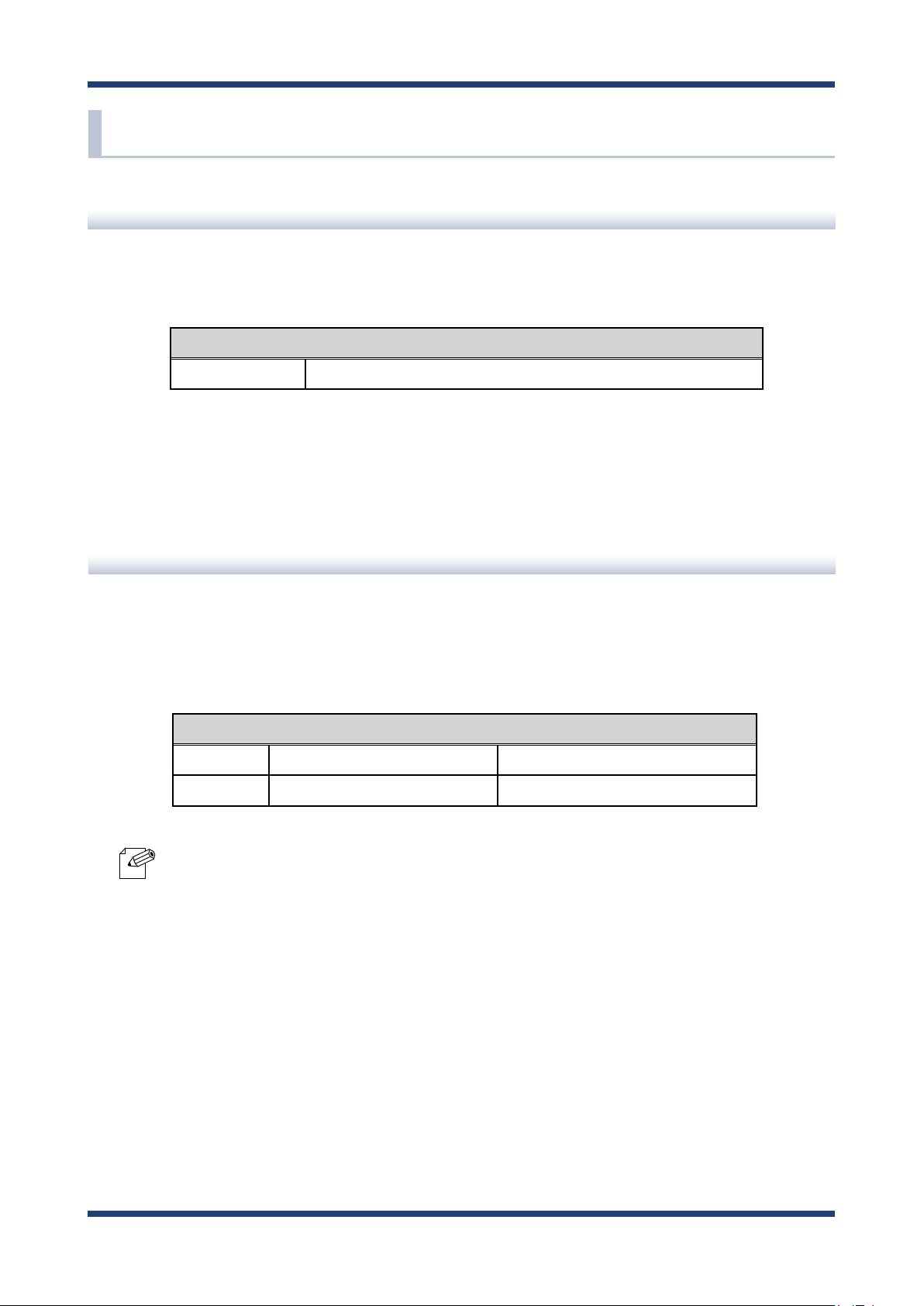
Product Information
The services below are available from the Silex Technology website. For details, please visit
the Silex Technology website.
URL
USA / Europe https://www.silextechnology.com/
- Latest rmware download - Latest software download
- Latest manual download - Support information (FAQ)
Customer Support Center
Customer Support is available by e-mail or telephone for any problems that you may
encounter. If you cannot nd the relevant problem in this manual or on our website, or if
the corrective procedure does not resolve the problem, please contact Silex Technology
Customer Support.
Contact Information
USA +1-657-218-5199 support@silexamerica.com
Europe +49-2154-88967-0 support@silexeurope.com
- Visit the Silex Technology website (https://www.silextechnology.com/) for the latest FAQ and product
information.
Note
5
Page 12

BR-400AN User's Manual
6
Page 13

2. Specications
2.
Specications
The Mesh network can easily be established using BR-400AN.
As 2.4GHz/5GHz wireless communication bands are supported, the wireless devices can
easily be joined to the Mesh network after they are connected to BR-400AN via a wired
LAN.
2-1. What is Mesh Network?
In the Mesh network, several Mesh-network compatible devices (hereinafter, "Mesh devices") are
connected each other to congure a network without using Access Point.
in a wider area as the range of radio wave can be expanded by relay.
Also, Mesh devices communicate each other regularly to select a best route for relay. For example, if a
device (BR-400AN(3)) has malfunctioned when the route (1) is used, the rest of devices will continue
communication by rebuilding the route (2).
BR-400AN(1)
BR-400AN(3) BR-400AN(5)
route (1)
route (2)
It allows communication
BR-400AN(2) BR-400AN(4) BR-400AN(6)
7
Page 14

BR-400AN User's Manual
2-2. Features
BR-400AN has the following features:
Giving unlimited locations for your non-wireless devices
As you do not have to care wiring conditions in order to establish your environment,
choices of location greatly expand in any kinds of scenes such as oce, factory, school,
commercial facility, etc. where the layout change is frequently required or effective
layout of equipment needs to be carefully considered for a work line. Also, since the
Mesh network can be created using two or more BR-400AN units, cost reductions could
be expected as you will not have to prepare Access Point for each channel.
IEEE 802.11a/b/g/n
BR-400AN supports communications at both 2.4GHz/5GHz bands. Using 5GHz band
will help to avoid radio interference with 2.4GHz band which is most commonly used in
the market.
Advanced security
The following security features are supported:
- WEP (64bit/128bit)
- WPA-PSK (AUTO/TKIP/AES), WPA2-PSK (AUTO/AES)
- IEEE 802.1X, WPA-Enterprise (AUTO/TKIP/AES), WPA2-Enterprise (AUTO/AES)
Two types of operating mode
< Mesh Point mode (hereinafter, "MP mode") >
- A radio wave is relayed from the other Mesh devices in the Mesh network. Also, the
wired devices can be used over the Mesh network via BR-400AN.
< Mesh Access Point mode (hereinafter, "MAP mode" >
- In addition to the MP mode function, Access Point function will run. BR-400AN can
be used as Access Point to connect wireless client devices.
On-board storage chip with 1GB memory
The operating log data can be stored in the on-board storage chip for a long period of
time. This will help you to quickly resolve the troubles that may occur during the use of
BR-400AN.
8
Page 15

2. Specications
Easy access to the Web conguration interface
Without changing the setting of the PC you use for setup, the Web configuration
interface of BR-400AN can easily be accessed.
AMC Manager® (non-free program) / AMC Manager® Free (free program)
BR-400AN supports the total management software, "AMC Manager®".
The AMC Manager® provides the useful features as follows:
- Remote device control and monitoring
- Bulk conguration
- IP address conguration -
Firmware updates
- Visualization of the Mesh network using Mesh Monitor (option utility)
- For details on the "AMC Manager®" and "Mesh Monitor", please visit our homepage.
Note
9
Page 16
BR-400AN User's Manual
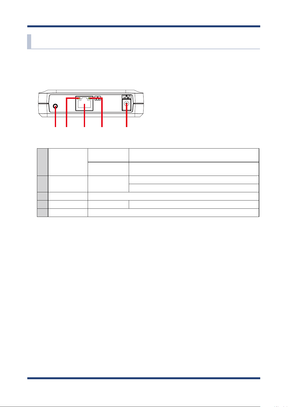
2-3. Parts and Functions
The parts name and functions are as follows:
(FRONT)
(1)
(2) (3) (4) (5)
Start in
(1)
Push Switch
(2) Status LED Blink (Orange)
(3) LAN port Connect a network cable.
(4) Link LED ON Has connected to a wired LAN.
(5) AC connector Connect an AC adaptor.
Conguration Mode
Factory default
conguration
Press and hold this switch for 5 sec while BR-400AN is active.
Press and hold this switch while turning on BR-400AN and release it
when the WLAN LED turns from Green to Red.
Waits for connection when the Link LED is turned o.
Handles data communication when the Link LED is turned on.
10
Page 17
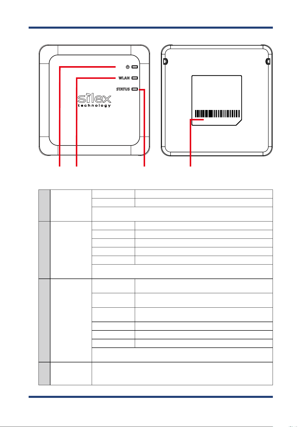
(TOP) (BOTTOM)
2. Specications
E/A:84253FXXXXXX
(6) (7) (8) (9)
(6) POWER LED
(7) WLAN LED
(8) STATUS LED
ON (Green) Powered on.
ON (Red) Turns on when BR-400AN is started in Conguration Mode.
* Turns green for 2 sec after BR-400AN is powered on and then turns o.
When the power-on process is completed, it turns green again.
ON (Green) Connected to the Mesh device in MP mode.
Blink (Green) Not connected in MP mode.
ON (Orange) Connected to the Mesh device in MAP mode.
Blink (Orange) Not connected in MAP mode.
Blink (Red) DFS function is in progress.
* Turns from Green to Red during the factory default conguration.
* Blinks Green together with the STATUS LED when operating in Conguration Mode.
ON (Green)
ON (Orange)
ON (Red)
Blink (Green) Data communication is in progress when link quality is good.
Connected to the Mesh device. The link quality is good and
communication with the Mesh device is stable.
Connected to the Mesh device. The link quality is OK and it is possible
to connect to the Mesh device.
Connected to the Mesh device. The link quality is poor and the
network environment needs to be improved.
(9) MAC Address
Blink (Orange) Data communication is in progress when link quality is OK.
Blink (Red) Data communication is in progress when link quality is poor.
* Does not blink when connection is not established.
* Blinks Green together with the WLAN LED when operating in Conguration Mode.
MAC Address of the LAN port on BR-400AN. The last 6-digit number is a serial number.
Example) If the MAC Address is "84:25:3F:00:11:22", it would be noted as "84253F001122"
and then the serial number is "001122".
11
Page 18

BR-400AN User's Manual
2-4. Hardware Specication
Operating environment
Storage environment
EMI VCCI Class-B
Wired network interface 10BASE-T/100BASE-TX/1000BASE-T (Auto-sensing) :1 port
Wireless network interface IEEE 802.11a/b/g/n
Channel (US/CA)
Push Switch 1
Temperature : 0 degrees to +40 degrees
Humidity : 20% to 80%RH (Non-condensing)
Temperature : -10 degrees to +50 degrees
Humidity : 20% to 90%RH (Non-condensing)
FCC Part15 SubPart B Class-B
ICES-003 Class-B
CE EN301489-1/-17 (EN55032 Class-B)
Auto MDI/MDIX
2.4GHz: 1-11ch
5GHz: (W52) 36,40,44,48
(W53) 52,56,60,64
(W56) 100,104,108,112,116,132,136,140
(W58) 149,153,157,161,165
(EU)
2.4GHz: 1-13ch
5GHz: (W52) 36,40,44,48
(W53) 52,56,60,64
(W56) 100,104,108,112,116,120,124,128,132,136,140
LED Top POWER (Green / Red / Orange)
WLAN (Green / Red / Orange)
STATUS (Green / Red / Orange)
LAN Port Status (Green / Orange)
Link (Green)
Compatible devices Network devices with LAN port (RJ-45)
FCC / IC Notice
FCCID : N6C-SXPCEAN2
IC : 4908A-SXPCEAN2
Channel Selection
For product available in the USA/Canada market, only channel 1~11 can be operated. Selection of other channels is not possible.
Fcc Rules Part 15
FCC CAUTION
Changes or modications not expressly approved by the party responsible for compliance could void the user’s authority to operate the
equipment.
12
Page 19

2. Specications
FCC Rules, Part 15 §15.19(a)(3) / IC RSS Gen §8.4
Below sentences must be indicated on the nal product which contains this module inside.
This device complies with Part 15 of FCC Rules and Industry Canada licence-exempt RSS standard(s). Operation is subject to the following
two conditions: (1) this device may not cause interference, and (2) this device must accept any interference, including interference that
may cause undesired operation of this device.
Le présent appareil est conforme à la partie 15 des règles de la FCC et CNR d'Industrie Canada applicables aux appareils radio exempts de
licence. L'exploitation est autorisée aux deux conditions suivantes : (1) l'appareil ne doit pas produire de brouillage, et (2) l'appareil doit
accepter tout brouillage subi, même si le brouillage est susceptible d'en compromettre le fonctionnement.
FCC Rules Part 15 Subpart C §15.247 and Subpart E / IC RSS-102 §2.6
This equipment complies with FCC/IC radiation exposure limits set forth for an uncontrolled environment and meets the FCC radio
frequency (RF) Exposure Guidelines and RSS-102 of the IC radio frequency (RF) Exposure rules. This equipment should be installed and
operated keeping the radiator at least 20cm or more away from person’s body.
Cet équipement est conforme aux limites d’exposition aux rayonnements énoncées pour un environnement non contrôlé et respecte les
règles les radioélectriques (RF) de la FCC lignes directrices d'exposition et d’exposition aux fréquences radioélectriques (RF) CNR-102 de l’IC.
Cet équipement doit être installé et utilisé en gardant une distance de 20 cm ou plus entre le radiateur et le corps humain.
FCC Rules Part 15 Subpart E §15.407(c)
Compliance with FCC requirement 15.407(c)
Data transmission is always initiated by software, which is the passed down through the MAC, through the digital and analog baseband,
and nally to the RF chip. Several special packets are initiated by the MAC. These are the only ways the digital baseband portion will
turn on the RF transmitter, which it then turns o at the end of the packet. Therefore, the transmitter will be on only while one of the
aforementioned packets is being transmitted.
In other words, this device automatically discontinue transmission in case of either absence of information to transmit or operational
failure.
FCC Rules Part 15 Subpart E §15.407(g)
Frequency Tolerance: +/-20 ppm
FCC Rules Part 15 Subpart C §15.247(g) / Subpart E
This device and its antenna(s) must not be co-located or operation in conjunction with any other antenna or transmitter.
RSS-Gen §8.3
This radio transmitter 4908A-SXPCEAN2 has been approved by Industry Canada to operate with the antenna types listed below with the
maximum permissible gain and required antenna impedance for each antenna type indicated. Antenna types not included in this list,
having a gain greater than the maximum gain indicated for that type, are strictly prohibited for use with this device.
Le numéro IC du présent émetteur radio 4908A-SXPCEN2 a été approuvé par Industrie Canada pour fonctionner avec les types d'antenne
énumérés ci-dessous et ayant un gain admissible maximal et l'impédance requise pour chaque type d'antenne. Les types d'antenne non
inclus dans cette liste, ou dont le gain est supérieur au gain maximal indiqué pour ce type, sont strictement interdits pour l'exploitation
avec cet appareil.
- Antenna type
External printed PCB antenna
- Model
H2B1PC1A1C
- Antenna Gain
2.4GHz : +1.8dBi (Peak)
5GHz : +3.9 dBi (Peak)
RSS-210
5150-5250 MHz and 5250-5350 MHz bands are restricted to indoor operations only.
High-power radars are allocated as primary users (i.e. priority users) of the bands 5250-5350 MHz and 5650-5850 MHz and that these
radars could cause interference and/or damage to LE-LAN devices.
La bandes 5150-5250 MHz et 5250-5350 MHz ont restreinte à une utilisation à l’intérieur seulement.
Les radars de haute puissance sont désignés comme utilisateurs principaux (c’est-à dire utilisateurs prioritaires) pour les bandes 52505350 MHz et 5650-5850 MHz, et que ces radars peuvent provoquer du brouillage et/ou des dommages aux dispositifs LAN-EL.
WARNING
The FCC / The Industry Canadaregulations provide that changes or modications not expressly approved by the party responsible for
compliance could void the user’sauthority to operate the equipment.
CE Notice
13
Page 20

BR-400AN User's Manual
2-5. Software Specication
Normal Mode
TCP/IP Network layer ARP, IP, ICMP, RSTP
Transport layer TCP, UDP
Application layer HTTP, DNS client, DHCP client, NTP, FLDP, SX-SMP
* FLDP, SX-SMP are the silex proprietary protocols.
Conguration Mode
TCP/IP Network layer ARP, IP
Transport layer TCP, UDP
Application layer HTTP, DNS(simple reply function only), DHCP (simple server function only),
NetBIOS over TCP/IP (Name Service only), FLDP
* FLDP is the silex proprietary protocol.
14
Page 21
2. Specications
2-6. Optional Utilities
By using the following optional utilities, the Mesh network can be visualized and the time
of device management can be reduced.
- AMC Manager®
- Mesh Monitor
What is AMC Manager®?
AMC Manager® is the unified device management utility that provides remote status
monitoring and individual/bulk conguration for Silex devices over an IP network.
If AMC Manager® is used, the BR-400AN's operating status can be shown as a list.
15
Page 22
BR-400AN User's Manual
As shown in the image below, AMC Manager® can congure IP address and write the same
setting to several units at once.
IP address: Congured by DHCP
Mesh setting: Default
IP address: 192.168.0.1
Mesh setting: Conguration A
IP address: Congured by DHCP
Mesh setting: Default
↓
IP address: 192.168.0.2
Mesh setting: Conguration A
- Congure an
an address from 192.168.0.1 - 192.168.0.3.
- Change the Mesh setting from default one to the
conguration A.
↓
BR-400AN (2) BR-400AN (3)
IP address to BR-400AN (1)-(3) by applying
BR-400AN (1)
Bulk conguration
PC
(AMC Manager® installed)
IP address: Congured by DHCP
Mesh setting: Default
↓
IP address: 192.168.0.3
Mesh setting: Conguration A
For AMC Manager®, there are a free version "AMC Manager® Free" and a non-free version
"AMC Manager®". When a non-free version is used, more devices can be managed and
congured at once and the plug-in utilities such as Mesh Monitor, etc. can be used.
Function
AMC Manager® Free
(Free version)
AMC Manager®
(Non-free version)
Number of controllable devices Up to 10 devices Up to 10,000 devices
Number of devices that can be controlled at a time Up to 10 devices Up to 10,000 devices
Number of groups that can be created Up to 2 devices Up to 100 devices
Number of devices that can be registered per group Up to 10 devices Up to 1,000 devices
Plug-in utility such as Mesh Monitor Unavailable Available
- To use AMC Manager® (non-free version), the license key needs to be purchased.
TIP
- If you are interested in purchasing the license, please contact us. For the contact information, refer to 1-3.
User Registration and Customer Services - Customer Support Center.
16
Page 23
2. Specications
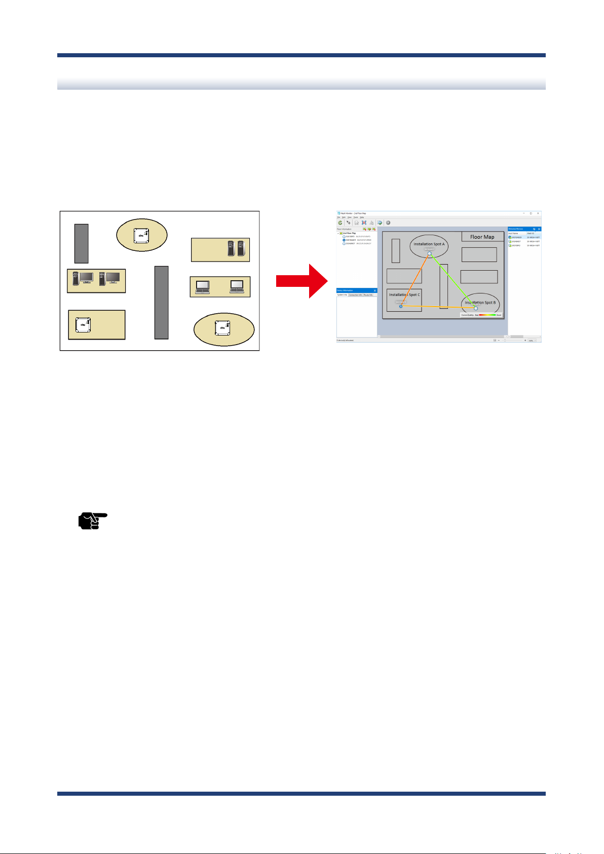
What is Mesh Monitor?
Mesh Monitor is a non-free plug-in utility of AMC Manager®.
Mesh Monitor can visualize the route setting and operating status to support the Mesh
network management.
Actual environment Display on Mesh Monitor
BR-400AN
BR-400AN
BR-400AN
As shown in the image above, the actual installation environment is simulated on Mesh
Monitor. The route information is displayed based on the actual route setting of BR-400AN.
It is possible to change some functions of BR-400AN using Mesh Monitor (e.g. enabling/
disabling Access Point function, etc.). Also, a history of Mesh network route and BR-400AN's
operating status can be checked and which can be used conveniently for troubleshooting.
- Mesh Monitor does not come with AMC Manager®.
TIP
- Mesh Monitor is a non-free plug-in utility of AMC Manager®. To install it, another license key needs to be
purchased.
- If you are interested in purchasing the license, please contact us. For the contact information, refer to 1-3.
User Registration and Customer Services - Customer Support Center.
17
Page 24

BR-400AN User's Manual
2-7. Wireless Interference Information
Notes of Use
Do not use BR-400AN near the following devices or places.
- Microwave, pacemaker, etc. of industrial, scientic and medical devices
- Licensed radio station in a factory
- Small power radio station (A non-licensed radio station)
These devices may use the same band. If you use BR-400AN near these devices, the radio
waves emitted from BR-400AN may interfere with them.
Do not use BR-400AN near a cellular phone, TV or Radio.
A cellular phone, TV and radio use a different radio band than our products. Generally,
if they are used near BR-400AN, it will not cause any problems. However, when they
approximate BR-400AN, sound or image noise may occur.
If there is reinforced concrete/metal between wireless devices, they may not connect.
BR-400AN can connect through wood or glass, but may have troubles connecting through
reinforced concrete/metal.
BR-400AN complies with the certification of conformance to technical standards.
Please pay attention to the following points:
- Please do not disassemble or remodel the product. Such action is prohibited by law.
- Please do not remove the certificate label. Using the product without a label is
prohibited.
18
Page 25

2. Specications
Wireless devices using 2.4GHz band
The same frequency band of BR-400AN is used for a microwave, industry, science, medical
equipment and licensed in room or low power (non-licensed) radio stations.
- Before you use BR-400AN, check that it does not interfere with other devices.
- If interference occurs, stop using BR-400AN or change the wireless band. Please
consider to create a wall between these devices to avoid interference. Contact us to
for possible solution.
* The meaning of the symbols in the bottom of the unit:
DS/OF2.4 4
2.4 : Wireless devices using 2.4GHz frequency band
DS/OF : DS-SS or OFDM is used as modulation.
4 : The range of interference is equal to or lower than 40m.
: All bands can be used to avoid interference.
Notes on using 5GHz band
Use of 5.2GHz band (W52) and 5.3GHz band (W53) outdoors is prohibited by the radio
law. When BR-400AN is used outdoors, use W56 channels only and do not use W52/W53
channels.
19
Page 26

BR-400AN User's Manual
DFS
BR-400AN supports DFS (Dynamic Frequency Selection) of the IEEE 802.11h wireless
standard. When radar signals are detected, the channel will automatically be switched to
avoid interference with radar systems (e.g. weather radar, etc).
One alternative channel can individually be set for W53/W56 channels beforehand, which
will be used when radar signals are detected and the channel needs to be switched.
When alternative channels are not specified or radar signals are detected even for that
channel, the channel is randomly is changed.
- If Use DFS Band is ON, the DFS channels can be used (it is set to OFF by default).
TIP
- When BR-400AN is started with a DFS channel, it checks if there are radar signals on that channel. During
such a period, BR-400AN is unable to communicate.
- If radar signals are detected during or after BR-400AN is powered on, the channel needs to be changed in
order to avoid wireless interference. Therefore, if DFS channels are selected, the channel could be changed
automatically.
- The radar signals are monitored for a certain amount of time (*) after it is detected, while wireless
communication is disabled on BR-400AN then. Once radar signals are detected, the channel will not be
available for 30 mins. (* This time period diers depending on the country.)
- If radar signals are detected when they are monitored, the channel is switched to CH36. If radar signals are
not detected by MP/MAP, a scan is handled on CH36. When connectable MP/MAP are found, the channel is
switched to CH36. When it is not found, the same channel is used. This operation is processed only when
the channel is W53.
- When the channel is switched after radar signals are detected, the destination channel is notied to the
adjacent MP/MAP. MP/MAP switches the channel when it receives the notication.
20
Page 27

2. Specications
2-8. Notes on Security
Because a wireless LAN uses electromagnetic signals instead of a network cable to
establish communication with network devices, it has the advantage of allowing devices
to connect to the network easily. However, a disadvantage of this is that within a certain
range, the electromagnetic signals can pass through barriers such as walls, and if security
countermeasures are not implemented in some way, problems such as the following may
occur.
- Communication is intercepted by a third party
- Unauthorized access to the network
- Leakage of personal information (ID and Card information)
- Spoong and the falsication of intercepted data
- System crashes and data corruption
Nowadays, wireless LAN cards or access points are equipped with security measures
that address such security problems, so that you can enable security-related settings for
wireless LAN products in order to reduce the likelihood of problems occurring.
We recommend that you make yourself fully acquainted with the possible implications
of what might happen if you use a wireless product without enabling security features,
and that you configure security-related settings and use wireless products at your own
responsibility.
21
Page 28

BR-400AN User's Manual
2-9. Restrictions
BR-400AN has the following restrictions.
Restrictions on DFS Channels
- If radar signals are detected again during the radar monitoring period that occurs as a
result that radar signals are found when BR-400AN is started or operating (*), BR-400AN
may not be able to join the network of adjacent MP/MAP.
- For some wireless environments, even if the destination channel is notified to the
adjacent MP/MAP, the channel switch may not perform as the notication is not received
correctly.
- If BR-400AN is restarted after it detected radar signals and switched the channel, BR400AN starts with the pre-congured channel NOT with the channel it switched. If the
channel is different from the adjacent MP/MAP, BR-400AN will not be able to join the
same network.
(* This time period diers depending on the country.)
22
Page 29

3. How to Install BR-400AN
3.
How to Install BR-400AN
This chapter provides the notes and examples of installation.
3-1. How to Install BR-400AN
The wireless distance, installation method and power-on method are explained.
23
Page 30
BR-400AN User's Manual
Top of
BR-400AN
View from side
View from top
View from front
2m
20m
20m
20m
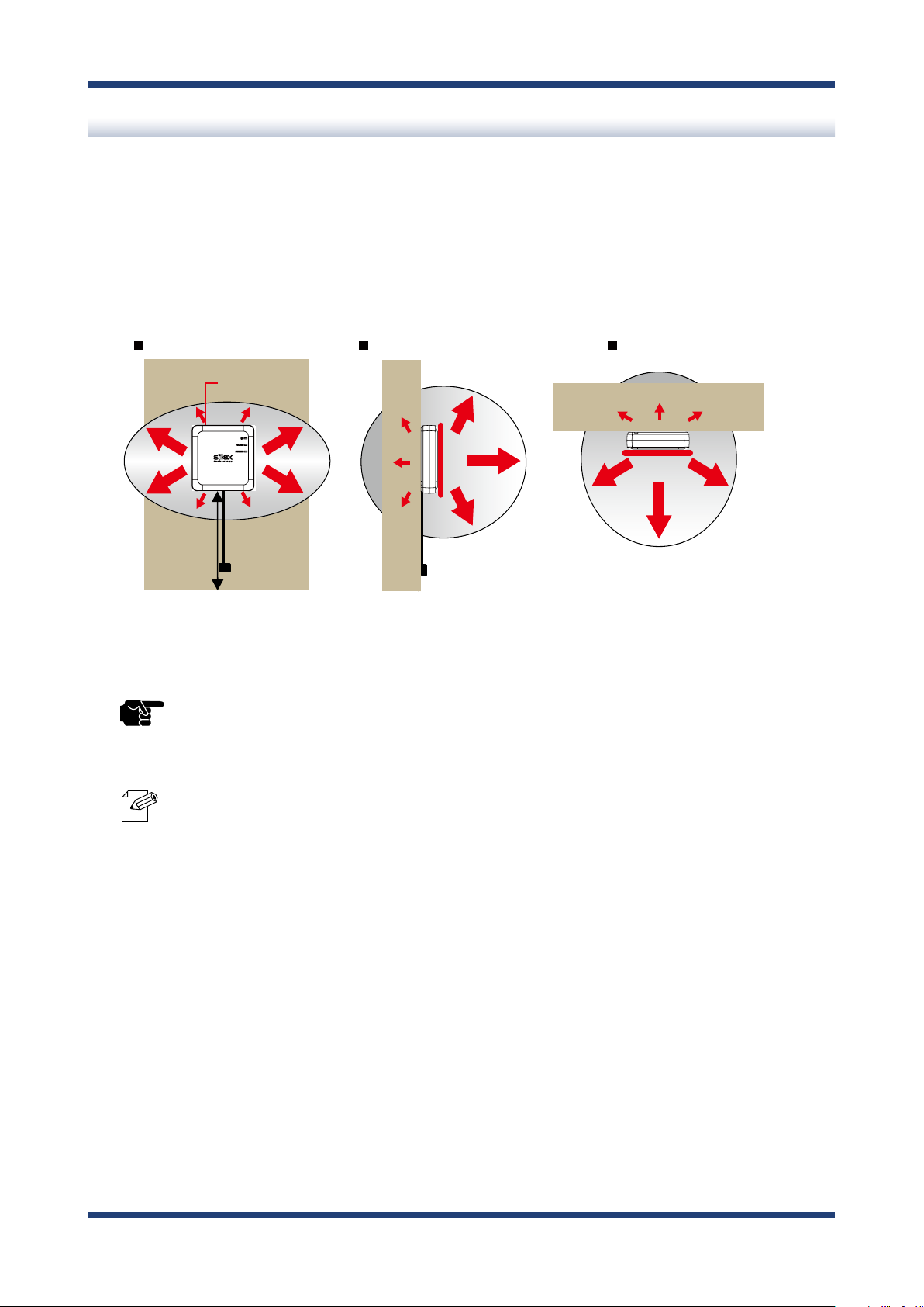
Product Installation and Radio Distance
BR-400AN radiates radio waves. Make sure that the top surface of BR-400AN (the surface
with Silex logo and LEDs) face a target device.
As a wireless communication distance is set to approximately 20m by defaults, place the
target device within that range. The height of installation position must be about 2m from
the ground.
TIP
Note
- An actual wireless communication distance may vary depending on wireless signal status on your
environment.
- By changing the transmission power setting on BR-400AN, the wireless communication distance can be
expanded / shortened. For details, refer to 5-1. Conguration Items on BR-400AN's Web Page - Option
Conguration page.
24
Page 31

3. How to Install BR-400AN
BR-400AN
(2)
Electrical outlet
AC adaptor
(1)
BR-400AN
Turns Green
Turns Green
Blinks Green
Turns Green
Blinks Green
OFF
BR-400AN
(1) When BR-400AN is started
(2) When the Mesh network is congured (link quality is good)
BR-400AN
Turns Green
Turns Green
Blinks Orange
(3) When the Mesh network is congured
(link quality is ok)
BR-400AN
Turns Green
Turns Green
Blinks Red
(4) When the Mesh network is congured (link quality is poor)
How to Turn on BR-400AN
Below explains how to turn on BR-400AN and how the LED lights when BR-400AN is
operating correctly.
Connect the AC adapter to BR-400AN (1) and the AC plug to outlet (2).
1.
2.
When BR-400AN is started, the LED turns on or blinks as shown at (1).
When the Mesh network is congured, the LED turns on or blinks as shown at (2)(3)(4).
- When BR-400AN is operating in MAP mode, the WLAN LED turns or blinks orange.
- To improve a link quality, conrm the followings and change the location of installation if necessary.
Note
- No reinforcing bars, metal and concrete walls or poles are installed in front of the radio emission portion.
- Not too far away from the other BR-400AN units
- The bottom surface of BR-400AN is not facing a concrete wall.
25
Page 32

BR-400AN User's Manual
3-2. Example of Installation
BR-400AN can congure various types of the Mesh network by changing the combination
of settings and devices.
In this section, some examples of typical installation are introduced.
See the example that best matches your environment to install BR-400AN.
- When the Mesh network is established using BR-400AN only
- When BR-400AN is connected to your existing network
- When the Mesh network is divided for each area
- When tablet devices or PCs are connected wirelessly
26
Page 33

3. How to Install BR-400AN
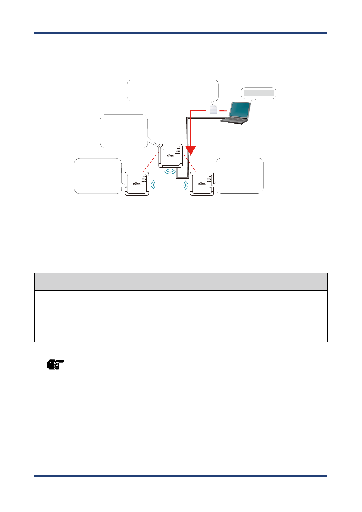
Conguring Mesh network using BR-400AN only
The following is a sample conguration image for the Mesh network using BR-400AN only
without using the existing network.
IP device
Network cable
BR-400AN (2)
Route(2)
BR-400AN (1)
BR-400AN (3)
PC (A)
Network cable
Route(1)
BR-400AN (4)
PC (B)
Network cable
Note
- The sample network above can be congured by default setting.
- If a valid IP address has already been congured to each device and they can communicate among each
other, you do not have to install a new DHCP server to congure the Mesh network.
- As long as a valid IP address is congured, PC (A), PC (B) and IP device can communicate with each other.
- As shown in above image, even if an error occurs to BR-400AN (4) and the route (1) becomes unavailable,
the devices will continue to communicate through the route (2).
- The communication speed can be improved by selecting DISABLE for Avoid Network Loop on all BR-
400AN units.
27
Page 34

BR-400AN User's Manual
Connecting BR-400AN to your existing network
The following is a sample conguration image for the Mesh network when adding multiple
BR-400AN units to your existing network.
Existing Network
Server
Network cable
BR-400AN (2)
Route(2)
IP device
Ethernet HUB (1) Ethernet HUB (2)
Network cable
PC (A)
BR-400AN (1)
Route(1)
BR-400AN (4)
PC (B)
28
TIP
Note
BR-400AN (3)
- When 2 or more BR-400AN units are connected to the same existing network via wired LAN, Avoid
Network Loop must be set to ENABLE (by default, this setting is enabled).
- The sample network above can be congured by default setting.
- If a valid IP address has already been congured to each device and they can communicate among each
other, you do not have to install a new DHCP server to congure the Mesh network.
- As long as a valid IP address is congured, PC (A), PC (B) and IP device can communicate with each other.
- As shown in above image, even if an error occurs to BR-400AN (4) and the route (1) becomes unavailable,
the devices will continue to communicate through the route (2).
- The communication speed can be improved by selecting DISABLE for Avoid Network Loop on the BR-
400AN units (2)-(4).
Network cable
Page 35

3. How to Install BR-400AN
Dividing the Mesh network for each area
The Mesh network can be configured separately for each section of the area where BR400AN units are installed. The following is the example of how to configure the Mesh
network for each section. For this, Mesh ID and Mesh encryption key need to be changed
for each area.
For details, refer to 5-1. Configuration Items on BR-400AN's Web Page - Basic
Conguration page.
IP device(1)
Network cable
PC (A)
BR-400AN(2)
Network cable
Ethernet HUB(3)
Ethernet HUB(1) Ethernet HUB(2)
BR-400AN(4)
Route(1)
Route(2)
Network cable
BR-400AN(7)
BR-400AN(8)
Server(A)
BR-400AN(1)
Server(B)
BR-400AN(5) BR-400AN(6)
BR-400AN(3)
Network cableNetwork cable
BR-400AN(9)
BR-400AN(10)
PC (B)
Network cable
PC (C)
BR-400AN(11)
BR-400AN(12)
Network cable
Network cable
IP device(2)
Network cable
IP device(3)
TIP
Note
- When 2 or more BR-400AN units are connected to the same existing network via wired LAN, Avoid
Network Loop must be set to ENABLE (by default, this setting is enabled).
- If a valid IP address has already been congured to each device and they can communicate among each
other, you do not have to install a new DHCP server to congure the Mesh network.
- As long as a valid IP address is congured, each PC, server and IP device can communicate with each other.
- As shown in above image, even if an error occurs to BR-400AN (9) and the route (1) becomes unavailable,
the devices will continue to communicate through the route (2).
- The communication speed can be improved by selecting DISABLE for Avoid Network Loop on the BR-
400AN units which are not connected to the Ethernet HUB.
29
Page 36

BR-400AN User's Manual
Connecting tablet devices or PCs wirelessly
By using the Access Point function of BR-400AN, wireless client devices (PC, tablet device,
etc.) can be connected to the Mesh network.
For details on how to enable the Access Point feature of BR-400AN and connect wireless
client devices, refer to 6. How to Connect Wireless Client Devices.
Existing Network
Server
Network cable
BR-400AN (2)
Route(2)
IP device
Network cable
BR-400AN (3)
Ethernet HUB (1) Ethernet HUB (2)
PC (A)
BR-400AN (1)
Route(1)
BR-400AN (4)
PC (B)
Tablet
30
TIP
Note
- When 2 or more BR-400AN units are connected to the same existing network via wired LAN, Avoid
Network Loop must be set to ENABLE (by default, this setting is enabled).
- If a valid IP address has already been con gured to each device and they can communicate among each
other, you do not have to install a new DHCP server to congure the Mesh network.
- As long as a valid IP address is con gured, PC (A), PC (B), tablet device and IP device can communicate with
each other.
- As shown in above image, even if an error occurs to BR-400AN (4) and the route (1) becomes unavailable,
the devices will continue to communicate through the route (2).
- The communication speed can be improved by selecting DISABLE for Avoid Network Loop on the BR-
400AN units (2)-(4).
Page 37

4. How to Congure BR-400AN
PC
4.
How to Congure BR-400AN
This chapter explains how to congure BR-400AN.
The following conguration methods are available:
1) Conguration via the BR-400AN's Web page
2) Conguration using AMC Manager®
3) Conguration using Mesh Monitor
4-1. Conguration via BR-400AN's Web Page
Below explains how to congure BR-400AN via its Web page.
If you know the IP address of BR-400AN, the Web page can be accessed by entering the
IP address to the address bar of Web browser. If you do not know the IP address, the Web
page can be accessed by starting BR-400AN in conguration mode.
Accessing the BR-400AN's Web Page Using Conguration Mode
How to access the BR-400AN's Web page using the conguration mode is explained.
Connect BR-400AN and the PC using a network cable (1) and turn on BR-400AN (2)(3).
1.
Outlet
(3)
(1)
BR-400AN
(1)
Network cable
(2)
AC adapter
31
Page 38

BR-400AN User's Manual
(2)
Push Switch
Push
(4)
Release
Push Switch
WLAN
Turns Green
Turns or
Blinks Green
WLAN
(1)
(3)
STATUS
Blinks Green
Turns Red
On top surface of BR-400AN, check that the POWER LED turns green and the WLAN LED
2.
turns or blinks green/orange (1). Push and hold the push switch on the front surface (2).
When the POWER LED turns red and the WLAN LED and the STATUS LED start to blink
green together (3), release the push switch (4) (it may take 20 sec until both LEDs start
to blink).
BR-400AN will start to run in a conguration mode and conguration will become
available on the PC that has been connected to BR-400AN using the network cable.
TIP
- When BR-400AN is started, only the POWER LED turns green for 2 sec and then turns o. If the push switch
is pushed then, BR-400AN is not started in the conguration mode.
- Before you push the push switch, check that the POWER LED turns green and the WLAN LED turns or blinks
green/orange.
32
Page 39

4. How to Congure BR-400AN
Start a Web browser (Edge, Internet Explorer, Google Chrome, etc.) on the PC.
3.
The Web page of BR-400AN is displayed.
Enter the password of BR-400AN and click Login.
- The login page is not displayed when the password is not set to BR-400AN.
- If the login page is not displayed even though the password is set to BR-400AN, enter "http://silex" in the
Note
address bar of the Web browser and press the Enter key.
33
Page 40

BR-400AN User's Manual
Accessing BR-400AN's Web Page over Network
If you know the IP address of BR-400AN, BR-400AN does not need to be started in the
configuration mode. Access the BR-400AN's Web page from your PC and change the
conguration from the Web page.
Start a Web browser (Edge, Internet Explorer, Google Chrome, etc.) on the PC and enter
1.
the IP address of BR-400AN to the address bar of the Web browser.
The login page of BR-400AN is displayed.
2.
Enter the password of BR-400AN and click Login.
- The login page is not displayed when the password is not set to BR-400AN.
34
Note
Page 41

4. How to Congure BR-400AN
Conguration via BR-400AN's Web Page
When the login password authentication is successfully finished, the window below is
displayed. When the login password is not set, the login page is skipped and the window
below is immediately displayed.
(1) (3) (4)
(2)
(5)
(5)
(6) (7)
35
Page 42

BR-400AN User's Manual
(1) Menu
If clicked, the conguration page is changed.
(2) Tab
The tab is displayed when there are multiple pages for the conguration. If the tab is
clicked, the conguration page is changed.
(3) Conguration page
Each setting can be congured.
(4) Link to Help
The Help page is displayed. The Help page provides the detailed explanation of each
setting.
(5) Firmware version / MAC address
The rmware version and MAC address of BR-400AN are displayed.
(6) Submit (Save) button
If clicked, the changes you made to the configuration page will be saved. (You may
need to scroll-down the screen to nd this button.)
(7) Clear button
If clicked, the changes you made to this conguration page will be cleared. (You may
need to scroll-down the screen to nd this button.)
- Be sure to change the password when BR-400AN is connected to a public network.
- Be sure to use encryption when the Access Point feature of BR-400AN is used.
TIP
- The wireless bands of IEEE 802.11b/g and IEEE 802.11n/b/g are often in use by someone as a large
number of wireless devices are using that bands. In such a case, you may not be able to procure enough
communication bands for your use.
- Follow the radio law of your country when BR-400AN is used outdoors. There are restrictions on the
communication bands (channels) that you can use outdoors.
- When W53(52/56/60/64ch) or W56(100/104/108/112/116/120/124/128/132/136/140ch) is selected, you
may need to refer to the restrictions at 2. Specications - 2-7. Wireless Interference Information - DFS.
36
Page 43

4. How to Congure BR-400AN
Select the configuration page by clicking the menu or tab and enter the necessary
1.
settings. Click Submit when nished.
- For details on each conguration item, refer to 5. List of Conguration Items.
Note
The message below is displayed.
2.
Repeat 1 to continue the conguration.
37
Page 44

BR-400AN User's Manual
When the conguration is completed, restart BR-400AN.
3.
Click Restart from the menu (1) and Click Ye s (2).
(1)
(2)
BR-400AN is restarted.
4.
When the progress bar reaches the right end of the screen, the restart is completed.
Finish the Web browser then.
38
Page 45

4. How to Congure BR-400AN
4-2. Bulk Conguration Using
If the unied device management software AMC Manager® is used, several BR-400AN units
can be congured at once. The bulk conguration method is explained.
- For details on AMC Manager®, refer to the AMC Manager® User's Manual.
Note
AMC Manager®
Preparation for Bulk Conguration
Create a conguration le for bulk conguration using AMC Manager®.
To create the conguration le, following items are necessary.
- PC (AMC Manager® needs to be installed)
1.
Start AMC Manager® on the PC.
39
Page 46

BR-400AN User's Manual
From the toolbar, click the icon Create the conguration le and select Create from
2.
Template.
- It is possible to read the setting from the conguration le if there is the one created in the past. For such a
case, click the icon Create the conguration le and select Edit Existing File.
Note
Select a template le for BR-400AN (1) and click OK (2).
3.
(1)
(2)
40
Page 47

4. How to Congure BR-400AN
4.
If a conguration category is clicked on the left side of the screen (1), the corresponding
setting is displayed on the right side (2).
(1) (2)
Check the check boxes of the settings to congure and edit them (1). When nished
5.
editing the necessary settings, click Save (2).
(1)
(2)
- If an IP address is specied in the conguration le, such address will be congured to all devices when the
TIP
same conguration le is used for them. Clear the check box of IP address to avoid it.
- There is a combination of the settings unable to write into BR-400AN units. Below is the example.
- Wireless mode is set to 802.11n/b/g or 802.11n/a while WEP is enabled.
- WEP is enabled and incompatible number of characters are used to specify WEP key.
- For other examples, refer to A-1. Troubleshooting.
41
Page 48

BR-400AN User's Manual
- The setting whose check box is checked will be congured to BR-400AN. For the setting you do not want
to change, clear the check box.
Note
Specify a le name to save the conguration le.
6.
- It is recommended to set/change the password to protect the setting information.
- Please be careful not to forget the Password, Mesh Group ID, Mesh Encryption Key, SSID, Security Key
(WEP Key or Pre-Shared key) to congure.
- It is possible to congure an IP address to several devices at once using AMC Manager®.
After the conguration is saved, the screen of 4 is displayed again.
To create a conguration for each Mesh network group, repeat 4-6.
When the configuration file is created, the preparation for bulk configuration is
completed. Click Close then.
42
Page 49

4. How to Congure BR-400AN
Starting Bulk Conguration
Multiple BR-400AN units can be congured at once using the conguration le that you
have created at Preparation for Bulk Conguration.
For bulk conguration, following items are required.
- PC (AMC Manager® needs to be installed)
- Network cable
1.
For the bulk conguration of IP address, the IP address of the PC needs to be changed
beforehand. Change the IP address of the PC to the one that can be communicated
with BR-400AN units after the bulk conguration.
Sample Setting)
Sample IP address setting for bulk conguration Sample IP address setting for PC
192.168.0.10 - 192.168.0.30
172.25.10.10 - 172.25.10.25 172.25.10.100
- The bulk conguration of IP address can be used for initial conguration.
TIP
192.168.0.100
43
Page 50

BR-400AN User's Manual
BR-400AN BR-400AN
2.
Turn on all BR-400AN units to congure, and connect a PC to one of them.
PC
BR-400AN
Network Cable
TIP
- The BR-400AN units to congure should temporarily be placed in a close location to congure the Mesh
network.
- Finish the bulk conguration before actual use of BR-400AN.
44
Page 51

4. How to Congure BR-400AN
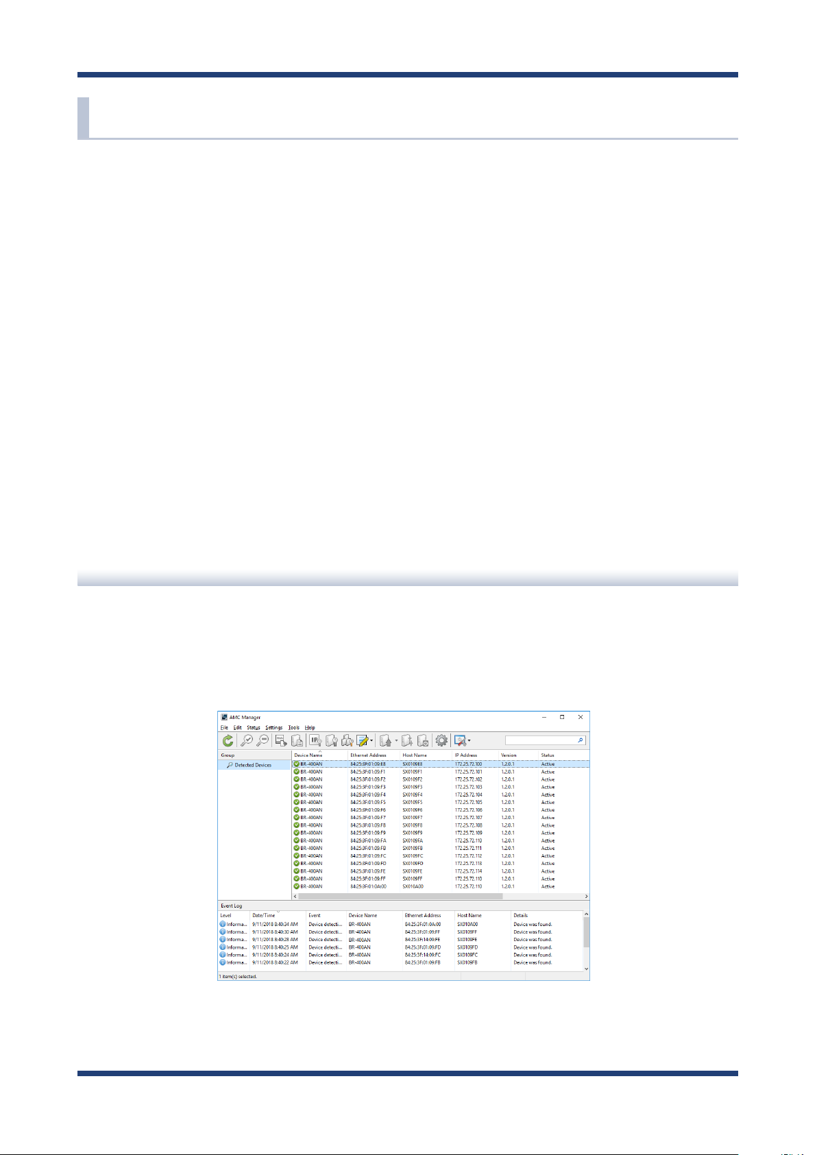
Start AMC Manager® on the PC.
3.
BR-400AN units are displayed on the device list when they are active on the Mesh
network.
Device list
- If the BR-400AN units are not displayed on the device list, click the icon Refresh.
- It may take approximately 1 min to show them on the device list depending on your environment.
Note
4.
Select the BR-400AN units to configure at once (1) and click the icon Configure
multiple devices in bulk (2).
(2)
(1)
45
Page 52

BR-400AN User's Manual
5.
Specify the conguration le. Select BR-400AN units to congure (1) and click Select
Cong. File (2).
(1)
6.
Select the conguration le that you have created beforehand.
(2)
46
Page 53

4. How to Congure BR-400AN
7.
The selected conguration le is displayed under Conguration File Name.
Repeat 5-6 to specify the conguration le for all BR-400AN units.
When the conguration le is specied for all BR-400AN units (1), click IP Conguration (2).
8.
(1)
(2)
47
Page 54

BR-400AN User's Manual
Specify the IP address range to congure for BR-400AN units (1).
9.
When the setting is nished, click OK (2).
(1)
(2)
- For example, if an IP address is congured to three units with the above setting, the rst one will obtain the
same address as the Start IP Address "172.25.72.100". As the Number of Steps is "0.0.0.1", the second one
Note
and the subsequent one will obtain "172.25.72.101" and "172.25.72.102" respectively.
The IP addresses to congure are pre-assigned and displayed under New IP Address.
10.
48
Page 55

4. How to Congure BR-400AN
11.
Check the check boxes of BR-400AN units to congure (1) and click Start (2).
(1)
(2)
- Please do not check the check box at Restart the device after this conguration. The conguration may
TIP
Note
12.
The progress bar is displayed during the configuration and the result is displayed when the
conguration is completed. Click Close when the conguration is completed.
fail as it makes all BR-400AN units restart regardless of the Mesh network status when the conguration is
completed.
- For changes to take eect, BR-400AN needs to be restarted.
- If the check box at the left of Device Name is checked, all check boxes are checked.
49
Page 56

BR-400AN User's Manual
Select File - Exit from the menu to nish AMC Manager®.
Turn o the BR-400AN units. When the BR-400AN units are turned on again at the place
where you actually use them, they will start with the new settings.
50
Page 57

4. How to Congure BR-400AN
BR-400AN
(1) Link quality is good
BR-400AN
(3) Link quality is poor
BR-400AN
(2) Link quality is ok
Turns Green
Turns Green
Turns Green
Turns Green
Turns Green
Turns Green
Blinks Green
Blinks Orange
Blinks Red
Product Installation
1.
After the bulk conguration is completed, bring one of BR-400AN units to a location of
installation. Start the BR-400AN before you x it to that location.
2.
Check the STATUS LED of the BR-400AN.
When it congures the Mesh network, the STATUS LED turns as follows according to a
link quality.
- When Route Refresh Function is set to DISABLE, the link quality is not refreshed unless the number of
TIP
Note
BR-400AN units increases or decreases in the Mesh network. It is recommended to set ENABEL for Route
Refresh Function until you nish installation.
- When the STATUS LED turns red, adjust the location of the BR-400AN. Refer to 3 for details.
- The link quality is the average value of communication quality for each route. To check the communication
quality value of BR-400AN, Mesh Monitor is required.
- When the communication quality is good, it has a higher transmission rate and stable communication.
- The refresh interval for the link quality changes according to the value of Route Refresh Interval.
If the value of Route Refresh Interval is set smaller, the refresh interval of the link quality becomes shorter.
- The STATUS LED blinks when the packets are sent or received.
- When the BR-400AN is operating in MAP mode, the WLAN LED turns orange.
51
Page 58

BR-400AN User's Manual
3.
To improve a link quality, conrm the followings and change the location of installation
if necessary.
- No reinforcing bars, metal and concrete walls or poles are installed in front of
the radio emission portion.
- Not too far away from the other BR-400AN units
- The bottom surface of BR-400AN is not facing a concrete wall.
4.
Repeat 1-3 and adjust the unit location one by one. When the adjustment is nished for
all units, x them to the location.
The product installation is now completed.
52
Page 59

4. How to Congure BR-400AN
4-3. Conguration Change Using Mesh Monitor
Some of the BR-400AN's setting can be changed using Mesh Monitor.
The setting can be changed also by using AMC Manager but if Mesh Monitor is used, you
can check the simulated Mesh route to change the setting.
- For details on Mesh Monitor, refer to the Mesh Monitor User's Manual.
- The following settings can be configured using Mesh Monitor. For details on each setting, refer to 5-1.
Note
Conguration Items on BR-400AN's Web Page.
- Host name
- Route refresh function
- Route refresh method
- Route refresh interval
- Access Point function
- Network loop avoidance
Select a single BR-400AN unit on Mesh Monitor (1) and click the icon Device
1.
conguration from the toolbar (2).
(2)
(1)
- The setting can also be changed by following methods.
- Select BR-400AN and click Tools - Device Conguration.
Note
- Right-click on BR-400AN and select Device Conguration from the context menu.
- When the password is set to BR-400AN, the password authentication dialog is displayed. Enter the password
of BR-400AN (1) and click OK (2).
53
Page 60

BR-400AN User's Manual
(1)
(2)
In the device conguration window, change the setting and click OK.
2.
(2)
- When the Access Point feature is enabled, SSID, authentication method and encryption mode also need
TIP
The result of conguration change is displayed
3.
Click OK to close the window.
to be congured. For details on the conguration, refer to 5-1. Conguration Items on BR-400AN's Web
Page - Access Point Function Conguration Page.
(1)
54
Page 61

5. List of Conguration Items
5.
List of Conguration Items
This chapter explains the BR-400AN's conguration items.
5-1. Conguration Items on BR-400AN's Web Page
In the Web page, following settings can be congured.
Basic Conguration
- Host name
- IP address
- Wireless setting (frequency band, etc.)
- Mesh network setting
Access Point Function
- Access Point function (ENABLE/DISABLE), operating setting (
method, etc)
- MAC address lter
Option Conguration
- TX power
- Wired LAN speed
- Time to switch into the conguration mode
- NTP function
Login Password
- Password
SSID, authentication
Hereinafter, the configuration items available on each page and the examples of
conguration are described.
55
Page 62

BR-400AN User's Manual
Basic Conguration
The basic settings (necessary settings to use BR-400AN mainly in MP mode) can be congured.
Basic Conguration - Host Name
Host Name
Details Set the host name. Be sure to use a unique name that is not used by other devices.
Range Up to 15 characters
Default Value SXxxxxxx (xxxxxx is a last 6-digit of the Ethernet Address)
Note This host name is displayed on AMC Manager® and Mesh Monitor.
Basic Conguration - IP Address
DHCP
Details
Range ENABLE/DISABLE
Default Value ENABLE
Enable/Disable the DHCP protocol.
To assign an IP address using DHCP, the DHCP server must be running in the same network.
IP Address
Details Congure the IP address.
Range 0.0.0.0 - 255.255.255.255
Default Value 0.0.0.0
Note When DHCP is enabled, the IP address obtained from DHCP server will be applied.
56
Page 63

Basic Conguration - IP Address
Subnet Mask
Details Congure the subnet mask.
Range 0.0.0.0 - 255.255.255.255
Default Value 0.0.0.0
Note
When DHCP is enabled, the subnet mask obtained from DHCP server will be applied.
When 0.0.0.0 is set, the subnet mask appropriate for the IP address class will automatically be assigned.
Default Gateway
5. List of Conguration Items
Details
Range 0.0.0.0 - 255.255.255.255
Default Value 0.0.0.0
Note
Set the gateway address. If "0.0.0.0" is set, this setting is disabled.
When DHCP is enabled, the default gateway obtained from DHCP server will be applied.
Basic Conguration - DNS Conguration
DNS Server (Primary)
Details Set a primary DNS server address.
Range 0.0.0.0 - 255.255.255.255
Default Value 0.0.0.0
Note When DHCP client is enabled, the DNS server address obtained from DHCP server will be applied.
DNS Server (Secondary)
Details Set a secondary DNS server address.
Range 0.0.0.0 - 255.255.255.255
Default Value 0.0.0.0
Note When DHCP client is enabled, the DNS server address obtained from DHCP server will be applied.
57
Page 64

BR-400AN User's Manual
Basic Conguration - Mesh General Conguration
Wireless Mode
Details Select the IEEE 802.11wireless mode.
Range 802.11b/g, 802.11n/b/g, 802.11a, 802.11n/a
Default Value 802.11n/b/g
802.11b/g : Uses IEEE802.11b or IEEE802.11g.
Note
802.11a : Uses IEEE802.11a.
802.11n/b/g : Uses IEEE 802.11n, IEEE 802.11b or IEEE 802.11g.
802.11n/a : Uses IEEE802.11n or IEEE802.11a.
Channel Bandwidth
Details
Range 20MHz/40MHz
Default Value 20MHz
Note
Set the frequency bandwidth.
This setting is necessary when using 802.11n/b/g or 802.11n/a.
40MHz (High speed) :
Uses double bandwidth.
Two neighboring bandwidths are combined together for high speed transmission.
20MHz (Standard) :
Uses standard (single) bandwidth.
If your network becomes unstable when using 40MHz, change it to 20MHz (Standard).
* Do not try to use 20MHz and 40MHz together in the same Mesh network.
Use DFS Band
Details Select whether to use the DFS band channel as a channel (ON/OFF).
Range ON / OFF
Default Value OFF
Note If this setting is enabled, the channels of DFS band can be selected for the channel setting.
58
Page 65

Basic Conguration - Mesh General Conguration
Channel
Set the wireless channel.
Details
Range
Default Value 11
Note
A channel is the divided frequency bandwidth. In a wireless network, bandwidth is divided up so that
more devices can communicate at a time.
The selectable channels will dier depending on the wireless mode.
When the wireless mode is 802.11b/g or 802.11n/b/g :
(US) 1-11
(EU) 1-13
When the wireless mode is 802.11a or 802.11n/a :
(US) 36/40/44/48/149/153/157/161/165
(EU) 36/40/44/48
If your network becomes unstable due to interference with other wireless devices, it could be improved
by changing the channel. The channel you can use will dier depending on the country.
When Use DFS Band is ON, the following channels can be used, however, if the following channels
are used and radar signals are detected when BR-400AN is turned on, communication will be lost for a
certain amount of time (*1).
(US/Canada) 52/56/60/64/100/104/108/112/116(*2)/132/136/140
(EU) 52/56/60/64/100/104/108/112/116/120/124/128/132/136/140
The extended channel setting will depend on the communication channel.
*1 This period of time will dier on each country.
*2 When Channel Bandwidth is 40MHz, 116ch cannot be used.
5. List of Conguration Items
Extension Channel
Details
Range
Default Value 7
Note When Use DFS Band is ON, the following channels can be used.
Set the extended channel when 40MHz is selected for channel bandwidth.
Available extended channels will dier depending on the channel.
When the wireless mode is 802.11b/g or 802.11n/b/g:
(US) 1-11
(EU) 1-13
When the wireless mode is 802.11a or 802.11n/a:
(US) 36/40/44/48/149/153/157/161
(EU) 36/40/44/48
(US/Canada) 52/56/60/64/100/104/108/112/132/136
(EU) 52/56/60/64/100/104/108/112/116/120/124/128/132/136
DFS Primary Channel
Set the alternative channel to use when radar signals are detected during DFS channels are used.
Details
Range
Default Value NONE
Note
If the alternative channel is not specified or radar signal is detected even for that channel, the
channel is randomly switched. For details on DFS channel switch, refer to 2-7. Wireless Interference
Information - DFS.
(US/Canada) NONE/52/56/60/64/100/104/108/112/116/132/136/140
(EU) NONE/52/56/60/64/100/104/108/112/116/120/124/128/132/136/140
When radar signals are detected on all channels, BR-400AN will switch the channel again in
approximately 30 mins, starting from the pre-congured channel.
59
Page 66

BR-400AN User's Manual
Basic Conguration - Mesh General Conguration
Mesh Group Name
Set a group name of the Mesh network to create or join (up to 32 characters).
Details
Range A string of 1-32 alphanumeric characters
Default Value SX-MESH-NET
The Mesh network is identied by the Mesh group name. To join the Mesh network, BR-400AN needs to
have the same Mesh group name as that Mesh network.
Mesh Encryption Key
Details Set the encryption key that BR-400AN uses for the Mesh network communication.
Range A string of 1-32 alphanumeric characters
Default Value silex technology, Inc.
Note The Mesh encryption key must be the same for all Mesh devices to join the Mesh network.
Basic Conguration - Mesh Route Conguration
Max Hop Count
Set the maximum number of the Mesh devices that BR-400AN can create the Mesh route for.
Details
Range 1, 2, 3, 4, 5, No Limit
Default Value 5
Note
The recommended number of hop is 5.
When 6 or more hops are needed, select No Limit. As the number of hops increases, the
communication speed decreases.
The number of hops represents the number of BR-400AN units to use for a communication relay.
This number should exclude the number of source unit (1 hop = 2 devices, 5 hops = 6 devices).
Route Refresh Function
Details Enable/Disable the regular optimization for the Mesh route.
Range ENABLE / DISABLE
Default Value ENABLE
Route Refresh Method
Set a refresh method for the Mesh route by selecting from the following options.
Light Refresh Mode :
Details
Range Light Refresh Mode / Full Refresh Mode
Reconstructs the route only in receiving direction to BR-400AN.
Full Refresh Mode :
Reconstructs the route in both receiving direction to BR-400AN and transmission direction from BR-
400AN.
Default Value Light Refresh Mode
60
Page 67

Basic Conguration - Mesh Route Conguration
Route Refresh Interval
Details Set a refresh interval for the Mesh route (sec).
Range 1-86400
Default Value 2
Basic Conguration - Mesh Route Conguration
Network Loop Avoidance
5. List of Conguration Items
Details
Range ENABLE /DISABLE
Default Value ENABLE
Note
Enable/Disable the network loop avoidance.
If this setting is enabled, BR-400AN handles a communication regularly to avoid a network loop.
If two or more BR-400AN units are connected to the existing network via wired LAN, this setting needs
to be enabled on all of them.
Sample Setting for Host Name
For the host name, enter a string with 15 or less characters.
If the host name is changed, you can easily identify that unit on AMC Manager® and
Mesh Monitor.
61
Page 68

BR-400AN User's Manual
Sample Setting for Mesh General Conguration
Congure the setting as follows when you want to use IEEE802.11n/a for Wireless Mode
and 40ch for Channel Bandwidth to congure the Mesh network.
Sample Setting for DFS Channel Use
To use the DFS band channels, select ON for Use DFS Band.
62
Page 69

5. List of Conguration Items
Sample Setting for Mesh Route Conguration
By conguring the Mesh route setting, you can set the action of BR-400AN to take when
the Mesh route is updated. For example, when you want to set '5' for Max Hop Count
and reconstruct the Mesh route in both receiving and transmitting direction in every 5
mins, congure the setting as below.
63
Page 70

BR-400AN User's Manual
Access Point Function Conguration Page
The Access Point function can be enabled/disabled and the detailed setting can be congured.
Access Point Function Configuration - Access Point Function Basic
Conguration
Access Point Function
Enable/Disable the Access Point feature.
Details
Range ENABLE / DISABLE
Default Value DISABLE
Note
If this setting is enabled, wireless clients (e.g. PC, tablet devices) are allowed to connect to BR-400AN.
Once the wireless clients are connected to BR-400AN, they can join the Mesh network.
For the wireless mode and channel to use for Access Point function, the settings of Mesh General
Conguration will be applied.
SSID
Details
Range A string of 1-32 alphanumeric characters
Default Value SX-MESH-AP
Set an SSID of the wireless LAN for BR-400AN. The SSID is an ID that distinguishes a wireless LAN
network from others.
Stealth Mode
Details Enable/Disable the stealth mode function.
Range ENABLE / DISABLE
Default Value DISABLE
When the stealth mode of BR-400AN is enabled, BR-400AN will not be found by the wireless client
Note
devices even when it is searched over the wireless LAN. To connect to BR-400AN, the SSID, authentication
method and encryption mode of BR-400AN need to be entered from the wireless client devices.
64
Page 71

5. List of Conguration Items
Access Point Function Configuration - Access Point Function Basic
Conguration
Network Authentication
Select the network authentication mode that will be used to connect to your wireless devices.
Details
Range
Default Value
To ensure a secure network, it is recommended to use WPA/WPA2.
When IEEE 802.11n is used, only AES can be used for encryption mode.
Open, Shared, WPA-PSK, WPA2-PSK, WPA/WPA2-PSK, 802.1X, WPA-Enterprise, WPA2-Enterprise, WPA/
WPA2-Enterprise
WPA2-PSK
Open (Open System):
Allows all access without authentication. For encryption mode, WEP can be used.
Shared (Pre-Shared Key):
Uses WEP key for encryption and allows access only from those with the same WEP key.
For encryption mode, WEP can be used.
WPA-PSK:
Uses PSK for network authentication. For encryption mode, TKIP/AES/AUTO can be selected.
The encryption key will be generated by communicating with your wireless devices using a Pre-
Shared key. WEP key setting is not used for this mode.
Note
WPA2-PSK:
Uses PSK for network authentication. For encryption mode, AES/AUTO can be selected.
The encryption key will be generated by communicating with your wireless devices using a Pre-
Shared key. WEP key setting is not used for this mode.
WPA/WPA2-PSK:
Uses both WPA-PSK and WPA2-PSK authentication.
802.1X:
Uses IEEE 802.1X user authentication and WEP encryption.
WPA-Enterprise:
Uses IEEE 802.1X user authentication and TKIP/AES/AUTO encryption.
WPA2-Enterprise:
Uses IEEE 802.1X user authentication and AES/AUTO encryption.
WPA/WPA2-Enterprise:
Uses IEEE 802.1X user authentication and AES/AUTO encryption.
When running in IEEE 802.11n, Shared and IEEE 802.1X authentication modes and WEP and TKIP
encryption modes cannot be used.
65
Page 72

BR-400AN User's Manual
Access Point Function Conguration - WEP Conguration
WEP
Enable/Disable WEP encryption.
Details
Range OFF / ON
Default Value OFF
If WEP encryption is used, wireless communication will be encrypted using the settings of WEP Key 1-4
and Key Index.
Note
If encryption is not enabled, data is not encrypted and is sent as is. To ensure higher security, enabling
encryption is recommended.
Key Index
Details
Range 1 - 4
Default Value 1
Select the number of the WEP key to use for encryption (1-4).
This setting must be the same as that of your wireless devices.
WEP Key1-4
Set the WEP key for WEP encryption.
Details
Range
Default Value (None)
Note
Up to 4 WEP keys can be set. This setting must be the same as that of your wireless devices. A WEP key
must be entered using hexadecimal or alphanumeric characters.
5 or 13 characters
10 or 26 digit value
In most cases, alphanumeric characters are used.
Enter 5 characters if the key size is 64bit or 13 characters if the key size is 128bit.
For Hexadecimal, a value consists of numbers (0-9) and English letters (A-F). Enter a 10-digit value if the
key size is 64bit or a 26-digit value if the key size is 128bit.
Access Point Function Conguration - WPA/WPA2 Conguration
Encryption Mode
Details
Range TKIP/AES/AUTO
Default Value AES
Note
66
Select the encryption mode to use for WPA-PSK, WPA2-PSK, WPA/WPA2-PSK, WPA-Enterprise,
WPA2-Enterprise, WPA/WPA2-Enterprise authentication.
When the network authentication mode is WPA2-PSK, WPA/WPA2-PSK, WPA2-Enterprise, WPA/
WPA2-Enterprise, TKIP cannot be used.
Page 73

5. List of Conguration Items
Access Point Function Conguration - WPA/WPA2 Conguration
Pre-Shared Key
Details Set the Pre-Shared Key to use for TKIP/AES encryption.
The Pre-Shared Key is a keyword used to create the encryption key. It is also referred to as ' network
key' or ' password '.
Range 8-63 alphanumeric characters
64 hexadecimal value
Default Value PreSharedKey
Note In most case, alphanumeric characters are used (8-63 characters).
For Hexadecimal, enter 64-character string that consists of numbers (0-9) and English letters (A-F).
This value must be the same as that of the wireless device you want to connect.
Group key renew interval
Details Set the refresh interval for Pre-Shared Key (min).
If 0 is set, this setting is disabled.
Range 0 - 1440
Default Value 60
Access Point Function Conguration - RADIUS Server Conguration
Server IP
Set the IP Address of RADIUS server.
Details
Range 0.0.0.0 - 255.255.255.255
Default Value 0.0.0.0
This needs to be set only when the network authentication is 802.1X, WPA-Enterprise, WPA2-
Enterprise or WPA/WPA2-Enterprise.
Port Number
Details Set the port number used to communicate with RADIUS server.
Range 0 - 65535
Default Value 1812
Shared Secret
Details Set the secret key used to communicate with RADIUS server.
Range Up to 32 characters
Default Value (None)
67
Page 74

BR-400AN User's Manual
Sample Setting for Access Point Function
When the Access Point function is enabled, some configuration items (SSID,
authentication method, encryption mode, etc.) will become available.
E.g.) To set WEP encryption for Access Point
E.g.) To set WPA2-PSK (authentication method) and AES (encryption mode) for Access
Point
68
Page 75

5. List of Conguration Items
E.g.) To establish the IEEE802.1X environment with RADIUS server and wireless client
devices
69
Page 76

BR-400AN User's Manual
Access Point Function Extended Conguration Page
The lter setting can be congured to allow or deny communication with a specic wireless
client device.
Access Point Function Extended Conguration - MAC Address Filter Conguration
Filter Type
Details Set a security type for MAC address lter to use over a wireless LAN.
Range DISABLE/DENY/ALLOW
Default Value DISABLE
MAC Address
Details
Range 00:00:00:00:00:01 - FF:FF:FF:FF:FF:FE
Default Value 00:00:00:00:00:00
Note
Register the MAC address of the target wireless client device to enable a lter for.
By registering the MAC address, access from a wireless LAN can be ltered.
If a lter type is DISABLE, access from all devices is allowed.
If a lter type is DENY, access from the devices registered to MAC Address lter list is denied.
If a lter is ALLOW, only access from the devices registered to MAC Address lter list is allowed.
70
Page 77

Sample Setting for MAC Address Filter
E.g.) To deny access from the specied wireless client device
E.g.) To allow access from the specied wireless client device only
5. List of Conguration Items
71
Page 78

BR-400AN User's Manual
Option Conguration Page
Transmission power, wired LAN, NTP function settings can be congured.
Option Conguration - TX Power Conguration
TX Power (%)
Set the transmission power for wireless LAN.
If a smaller value is set, a wireless distance from BR-400AN is shortened and the scope of search can
Details
Range 10, 20, 30, 40, 50, 60, 70, 80, 90, 100
Default Value 50
be narrowed down. By narrowing down the scope of search, interference to other network can be
reduced.
If a larger value is set, a wireless distance from BR-400AN is expanded and the scope of search can be
broadened. By broadening the scope of search, remote devices can be discovered.
Option Conguration - Wired LAN Conguration
Wired LAN Interface
Details Congure the physical network type.
Range AUTO/10Base-T-Half/10Base-T-Full/100Base-TX-Half/100Base-TX-Full/1000Base-T-Full
Default Value AUTO
Note
72
Usually, "AUTO" is used. When BR-400AN is powered on and the LINK LED does not turn on the device
that is connected to BR-400AN, change the network type to that of the device.
Page 79

Option Conguration - Push Switch Conguration
Time before turning into Conguration Mode (sec)
Specify the period of time until the BR-400AN turns into the Conguration Mode.
Details
Range 5-60 (sec)
Default Value 5
If the Push Switch is pressed for the period of time specied here, the BR-400AN will turn into the
Conguration Mode.
Option Conguration - NTP Conguration
NTP
Details Enable/Disable the NTP protocol.
Range ENABLE/DISABLE
5. List of Conguration Items
Default Value DISABLE
NTP Server
Details Set the domain name or IP address of the NTP server.
In case of the domain name;
Range
Default Value (None)
Alphanumeric character string (0-128 characters)
In case of the IP Address;
0.0.0.0 - 255.255.255.255
Local Time Zone
Details Set the local time zone.
Range -12:00 - +12:00
Default Value +9:00
Sample Setting of Transmission Power
By conguring the TX power, the wireless distance of BR-400AN can be changed.
The default value is set to 50(%). When the default value is used, the wireless distance
will be about 20m. When the value is changed to 100(%), the wireless distance will be
about 35m.
73
Page 80

BR-400AN User's Manual
Login Password Conguration Page
The password to login to the Web page can be congured.
Login Password Conguration
New Password
Set the login password (up to 16 ASCII characters).
Details
Range Alphanumeric character string (0-15 characters)
Default Value root
Note This password is also used to change conguration using AMC Manager® and Mesh Monitor.
This password is used for authentication when changing settings from the Web conguration page.
The new password needs to be entered again to Conrm New Password.
74
Page 81

6. How to Connect Wireless Client Devices
6.
How to Connect Wireless Client Devices
This chapter explains how to connect wireless client devices (PC, tablet, etc.) to BR-400AN.
6-1. How to Enable Access Point Feature on BR-400AN
To connect the PCs or tablet devices to BR-400AN, the Access Point feature needs to be
enabled on BR-400AN. Execute one of the following methods to enable the Access Point
feature.
1) Use the Web conguration interface to enable the Access Point feature.
2) Use AMC Manager® to enable the Access Point feature.
3) Use Mesh Monitor to enable the Access Point feature.
75
Page 82

BR-400AN User's Manual
How to enable the Access Point feature using the Web conguration interface
Access the Web conguration interface of BR-400AN using your Web browser, enter the
1.
password and click Login.
- For how to access the Web conguration interface, refer to 4-1.Conguration via BR-400AN's Web Page.
- The login page is not displayed when the password is not congured to BR-400AN.
Note
When the Web conguration interface is displayed, click Access Point Function.
2.
76
Page 83

Select ENABLE for Access Point Function.
3.
6. How to Connect Wireless Client Devices
The detailed setting of Access Point feature such as SSID, authentication method, etc.
4.
can be congured. For details on the congurable items, refer to 5-1. Conguration
Items on BR-400AN's Web Page - Access Point Function Conguration Page.
The wireless mode, channel bandwidth and channel cannot be changed in this page.
To change these settings, go to the Basic Conguration page.
(1)
(2)
77
Page 84

BR-400AN User's Manual
When the conguration is completed, restart BR-400AN.
5.
Note
- For details on how to restart BR-400AN, refer to 7-1. Restart.
78
Page 85

6. How to Connect Wireless Client Devices
How to enable the Access Point feature using AMC Manager®
1.
Start AMC Manager®, click the icon Create the configuration file - Create from
Template from the toolbar.
- If you have the conguration le, it is possible to read the setting from that le. In that case, click the icon
Create the conguration le - Edit Existing File.
Note
Select a template le for BR-400AN (1) and click OK (2).
2.
(1)
(2)
79
Page 86

BR-400AN User's Manual
3.
Select Wireless LAN I/F 1 from the conguration category on the left (1).
The corresponding setting items are displayed on the right (2).
(1)
(2)
Select Enable for Access Point Function and check the check box.
4.
80
Page 87

6. How to Connect Wireless Client Devices
Select Wireless LAN I/F 2 from the conguration category on the left (1), and congure
5.
the SSID, authentication and encryption settings on the right (2).
(1)
- Only the setting whose check box is checked will be congured to BR-400AN. Remote a check from the
setting that you do not want to change.
Note
When the conguration is completed, click Save.
6.
(2)
81
Page 88

BR-400AN User's Manual
Specify the le name and click Save.
7.
8.
Click Close.
82
Page 89

6. How to Connect Wireless Client Devices
9.
Select BR-400AN units to congure in bulk (1) and click the icon Congure multiple
devices in bulk (2).
(2)
(1)
Specify the conguration le to use. Select BR-400AN units to congure (1) and click
10.
Select Cong. File (2).
(1)
(2)
83
Page 90

BR-400AN User's Manual
11.
Select the conguration le that you have created at 7.
12.
The selected conguration le is displayed under Conguration File Name.
84
Page 91

6. How to Connect Wireless Client Devices
13.
Check the check boxes of BR-400AN units to congure in bulk (1) and click Start (2).
(1)
(2)
- Please do not check the check box at Restart the device after this configuration. If it is checked,
TIP
Note
14.
When the conguration is in progress, the progress bar is displayed and when the conguration
is nished, the result is displayed. Click Close.
BR-400AN units will automatically be restarted regardless of the Mesh network status and the bulk
conguration may not be completed correctly as the result.
- If the check box on the left of Device Name is checked, check boxes of all devices will be checked in the
list.
85
Page 92

BR-400AN User's Manual
15.
Restart all BR-400AN units.
For details on how to restart BR-400AN, refer to 7-1. Restart in this document or 4-9.
Restart in the AMC Manager® User's Manual.
BR-400AN units will start with a new setting after restart.
The Access Point feature has been enabled.
Click File - Exit to nish AMC Manager®.
86
Page 93

6. How to Connect Wireless Client Devices
How to enable the Access Point feature using Mesh Monitor
Select a single BR-400AN unit to enable the Access Point feature (1) and click the icon
1.
Device conguration from the toolbar (2).
(2)
Note
(1)
- The device conguration window can also be opened by the following methods:
- Select BR-400AN and click Tools - Device Conguration from the menu bar.
- Right-click on BR-400AN and select Device Conguration from the context menu.
- When the password is set to BR-400AN, the screen below is displayed. Enter the password (1) and click OK (2).
(1)
(2)
87
Page 94

BR-400AN User's Manual
Check the check box at Enable Access Point Function (1) and click OK (2).
2.
(1)
(2)
- When the Access Point feature is enabled, the SSID, authentication method and encryption mode will also
TIP
The result of conguration change is displayed.
3.
Click OK to close the device conguration window.
need to be congured. For details on the conguration method, refer to 5-1. Conguration Items on BR-
400AN's Web Page - Access Point Function Conguration Page.
88
Page 95

6. How to Connect Wireless Client Devices
6-2.
The following explains how to connect your Windows PC to BR-400AN as a wireless client.
Click the below icon from the task tray to open the wireless connection window.
1.
Select the SSID of BR-400AN from the list of wireless networks (1) and click Connect (2).
2.
How to Connect PCs or Tablets to BR-400AN
(1)
Note
(2)
- If the check box at Connect automatically is checked, the PC is automatically connected to BR-400AN
when it is started.
89
Page 96

BR-400AN User's Manual
Enter the security key of BR-400AN for Enter the network security key (1) and click
3.
Next (2).
(1)
(2)
When the message "Connected" is displayed, the Windows PC has been connected to
4.
BR-400AN.
90
Page 97

7. Maintenance Feature
7.
Maintenance Feature
This chapter explains the maintenance feature of BR-400AN.
7-1.
Execute one of the following methods to restart BR-400AN.
1) Restart BR-400AN by unplugging the AC adaptor
2) Restart BR-400AN using the Web conguration interface
3) Restart BR-400AN using AMC Manager®
Note
Restart
- For details on how to restart using AMC Manager®, see 4-9. Restart in the AMC Manager® User's Manual.
91
Page 98

BR-400AN User's Manual
Outlet
BR-400AN
AC Adaptor
(2)
(1)
How to restart BR-400AN by unplugging the AC adaptor
Unplug the AC adaptor of BR-400AN from the outlet (1) and plug it back into the outlet
1.
(2).
When the POWER LED turns green and WLAN LED turns or blinks green/orange, the
2.
restart is completed. After the restart, the BR-400AN will start in a normal mode.
BR-400AN
Turns green
Turns or Blinks green/orange
92
Page 99

7. Maintenance Feature
How to restart BR-400AN using the Web conguration interface
Access the Web conguration interface of BR-400AN using your Web browser, enter the
1.
password and click Login.
- For how to access the Web conguration interface, refer to 4-1.Conguration via BR-400AN's Web Page.
- The login page is not displayed when the password is not congured to BR-400AN.
Note
Click Reboot from the menu (1) and click Yes (2).
2.
(1)
(2)
93
Page 100

BR-400AN User's Manual
The restart is completed when all LEDs turn o and then the POWER LED turns green
3.
and the WLAN LED turns or blinks green/orange. BR-400AN will run in a normal mode
then.
BR-400AN
Turns green
Turns or Blinks green/orange
94
 Loading...