

Silent Witness V25 ArmorDome, V25 Series ArmorDome User Manual

V25 Series
ArmorDome™
CCTV Camera
User Guide

Contents
Overview . . . . . . . . . . . . . . . . . . . . . . . . . . . . . . . . . . . . . . . . . . . . . . . . . . . 1
Before You Begin . . . . . . . . . . . . . . . . . . . . . . . . . . . . . . . . . . . . . . . . . . . . . . 1
Unpacking and Inspection . . . . . . . . . . . . . . . . . . . . . . . . . . . . . . . . . . . . . 1
Equipment Required . . . . . . . . . . . . . . . . . . . . . . . . . . . . . . . . . . . . . . . . . 1
Initial Setup . . . . . . . . . . . . . . . . . . . . . . . . . . . . . . . . . . . . . . . . . . . . . . . . . 2
Disassembling the Camera . . . . . . . . . . . . . . . . . . . . . . . . . . . . . . . . . . . . . . . 2
Wall Mount Setup . . . . . . . . . . . . . . . . . . . . . . . . . . . . . . . . . . . . . . . . . . . . . . 3
Ceiling Mount Setup . . . . . . . . . . . . . . . . . . . . . . . . . . . . . . . . . . . . . . . . . . . . 4
Installation . . . . . . . . . . . . . . . . . . . . . . . . . . . . . . . . . . . . . . . . . . . . . . . . . . 6
Mounting the Camera on a Wall or Ceiling. . . . . . . . . . . . . . . . . . . . . . . . . . 6
Mounting the Camera in an Electrical Box. . . . . . . . . . . . . . . . . . . . . . . . . . . 7
Wiring . . . . . . . . . . . . . . . . . . . . . . . . . . . . . . . . . . . . . . . . . . . . . . . . . . . . . . . 7
Aiming and Focusing . . . . . . . . . . . . . . . . . . . . . . . . . . . . . . . . . . . . . . . . . . . 8
Changing the Quick Change Lens . . . . . . . . . . . . . . . . . . . . . . . . . . . . . . . 9
Dip Switch Functions (Color Cameras) . . . . . . . . . . . . . . . . . . . . . . . . . 10
Adjustment Method (Color Cameras) . . . . . . . . . . . . . . . . . . . . . . . . . . 11
White Balance Adjustment Method (Color Cameras) . . . . . . . . . . . . . 11
Manually Setting Shutter Speed (Color Cameras) . . . . . . . . . . . . . . . . . 12
Dip Switch Functions (Monochrome Cameras) . . . . . . . . . . . . . . . . . . 13
Adjustment Method (Monochrome Cameras) . . . . . . . . . . . . . . . . . . . 13
Adjusting the Line Lock (Vertical Phase) for 24 VAC Operation . . . . . 14
Adjusting the Backlight Compensation . . . . . . . . . . . . . . . . . . . . . . . . . 14
Installing the Front Plate and Dome . . . . . . . . . . . . . . . . . . . . . . . . . . . . . . 14
Routine Maintenance . . . . . . . . . . . . . . . . . . . . . . . . . . . . . . . . . . . . . . . . . . 14
Replacing the Dome . . . . . . . . . . . . . . . . . . . . . . . . . . . . . . . . . . . . . . . . . . . 15
Solving Common Technical Issues . . . . . . . . . . . . . . . . . . . . . . . . . . . . . 16
Service . . . . . . . . . . . . . . . . . . . . . . . . . . . . . . . . . . . . . . . . . . . . . . . . . . . . 17
Specifications . . . . . . . . . . . . . . . . . . . . . . . . . . . . . . . . . . . . . . . . . . . . . . 18
Cable Guidelines . . . . . . . . . . . . . . . . . . . . . . . . . . . . . . . . . . . . . . . . . . . . 20
Mounting Template . . . . . . . . . . . . . . . . . . . . . . . . . . . . . . . . . . . . . . . . . 21
V25 Model Numbers . . . . . . . . . . . . . . . . . . . . . . . . . . . . . . . . . . . . . . . . 22
Regulatory Compliance. . . . . . . . . . . . . . . . . . . . . . . . . . . . . . . . . . . . . . . 23
FCC Statement (U.S.A.) . . . . . . . . . . . . . . . . . . . . . . . . . . . . . . . . . . . . . . . . 23
Industry Canada Notice . . . . . . . . . . . . . . . . . . . . . . . . . . . . . . . . . . . . . . . . 23

Overview
The unobtrusive, low-profile design of the V25 ArmorDome™ CCTV Camera is
ideal for indoor and outdoor installations in commercial and residential venues.
Before You Begin
Please read this guide carefully before you install
the V25 ArmorDome CCTV Camera.
Keep this guide for future reference.
WARNING! The use of CSA Certified/UL Listed Class 2
power adapters is required to ensure
compliance with electrical safety standards.
Unpack Everything
Check that the items received match those listed on the order form and packing
slip. The V25 packing box should include, in addition to this Installation Guide:
• One security hex key
• Four #6-32 x 3/4 in. plated steel, Phillips head machine screws
• One #6 nylon washer
• One #6-32 x 3/8 in. stainless steel, Phillips head machine screw
If any parts are missing or damaged, please contact the dealer you purchased the
camera from, or call Silent Witness Customer Service. See “Service” on page 17.
Equipment Required
You will require the following tools to complete the installation:
• Phillips screwdriver
• Side-cutters
1
Initial Setup
Before installing the V25 Camera, you must first:
• Disassemble the camera.
• Set up the camera for mounting on a wall or a ceiling.
Disassembling the Camera
To disassemble the camera:
1. Use the security hex key provided to remove the three #6-32 x 3/8 in. machine
screws securing the V25 front plate and dome to the base (see Camera
Components). Set aside the screws.
2. Use a Phillips screwdriver to remove the two #6-32 x 1/4 in. machine screws
that attach the camera gimbal to the gimbal support bracket.
Do not remove the camera carrier from the gimbal at this time. Also, do not
disconnect the wires from the camera.
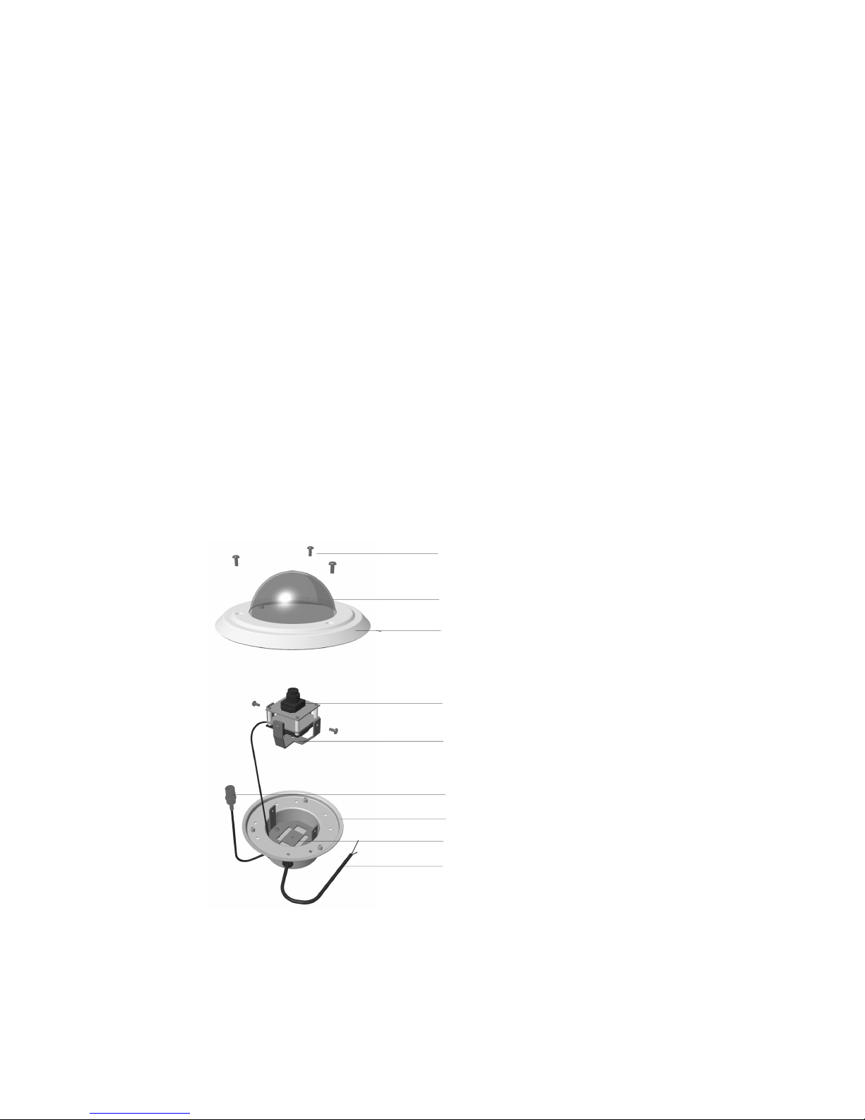
Figure 1 Camera Components
#6-32 x 3/8 in. Security head
machine screws (x3)
Dome
Front plate
Camera and carrier
Gimbal
Video output: female BNC
Base
Gimbal support bracket
Power input cable
If you are mounting the V25 Camera on a wall, proceed to Wall Mount Setup. If you
are mounting the V25 Camera on a ceiling, proceed to Ceiling Mount Setup.
2
Document 920.0090 Rev 3.00 April 16, 2002
Wall Mount Setup
When the V25 Camera is mounted on a wall, the camera carrier can be adjusted to
pan and tilt.
Once you have disassembled the camera, prepare the camera for mounting on a
wall:
1. Use a pair of side-cutters to remove the perforated square in the gimbal
support bracket (see Wall Mount Setup). Discard this square. This allows full
motion of the camera gimbal.
2. Use a Phillips screwdriver and two #6-32 x 1/4 in. machine screws to attach
the camera gimbal and camera carrier to the modified gimbal support bracket.
The V25 Camera is now set up for mounting on the wall. Proceed to Installation on
page 6.
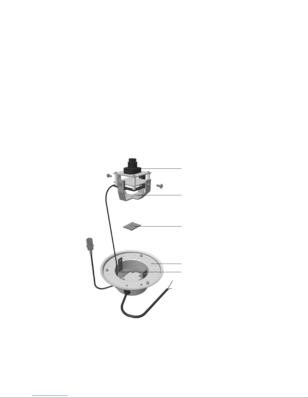
Figure 2 Wall Mount Setup
Camera and carrier
Gimbal
Discard center square
Base
Gimbal support bracket
(center square removed)
3

Ceiling Mount Setup
When the V25 Camera is mounted on the ceiling, the camera carrier can be
adjusted to rotate and tilt.
Once you have disassembled the camera, prepare the camera for mounting on a
ceiling:
1. Remove both arms from the gimbal support bracket by holding the end of the
arm and bending it back and forth until it breaks off (see Figure 3). Do not
remove the center square from the gimbal support bracket.
2. Use a Phillips screwdriver to remove the two #6-32 x 1/4 in. machine screws
that attach the camera carrier to the gimbal.
3. Use side-cutters to remove the two perforated arms of the gimbal.
4. Attach the gimbal to the gimbal support bracket (see Figure 3) using one #6-32
x 3/8 in. machine screw and a #6 nylon washer (provided). Tighten the screw.
Caution The nylon washer must be mounted between the gimbal
and the gimbal support bracket to allow the gimbal to
rotate clockwise without binding.
5. Use two #6-32 x 1/4 in. machine screws to attach the camera carrier to the
gimbal.
Caution Line-lock cameras have an electrically isolated camera
carrier to prevent ground loop problems. Ensure the nylon
bushings and insulating washers are installed as shown in
Figure 3.
The V25 Camera is now ready for mounting on a ceiling. Proceed to Installation on
page 6.
4
Document 920.0090 Rev 3.00 April 16, 2002
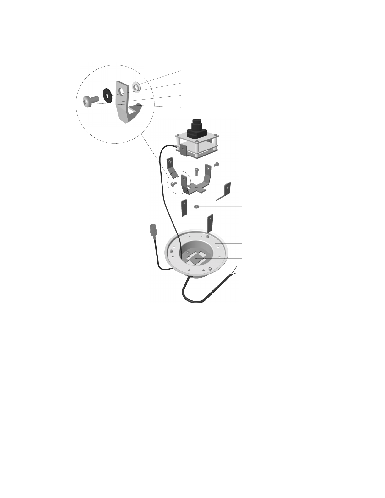
Figure 3 Ceiling Mount Setup Showing Electrical
Isolation of Line Lock Camera Carrier
Nylon bushing
Insulating washer
Gimbal
#6-32 x 1/4 in. machine screw
Camera and carrier
#6-32 x 3/8 in. machine screw
Gimbal (perforated
arms removed)
#6 nylon washer
Base
Gimbal support bracket
(arms removed)
5
Installation
The V25 Camera is designed to be flush mounted on a panel or in a standard deep
double-gang electrical box. The camera can be located indoors or outdoors, on a
wall or ceiling, in accordance with the current Electrical Code or any national wiring
rules that apply.
Follow the Initial Setup procedure before installing the V25 Camera.
Mounting the Camera on a Wall or Ceiling
To mount the V25 Camera on a wall or ceiling panel:
1. Mark and drill out mounting holes in the wall or ceiling panel (see Figure 4),
using the mounting template shown on page 21.
2. Insert the camera base into the mounting hole.
3. Secure the camera to the mounting panel using four #6-32 self-tapping screws
(not provided).
Note An optional V25 Backing Plate Kit is available to mount the V25
Camera in a removable ceiling panel as shown in Figure 4. Please
contact Silent Witness Sales for more information.
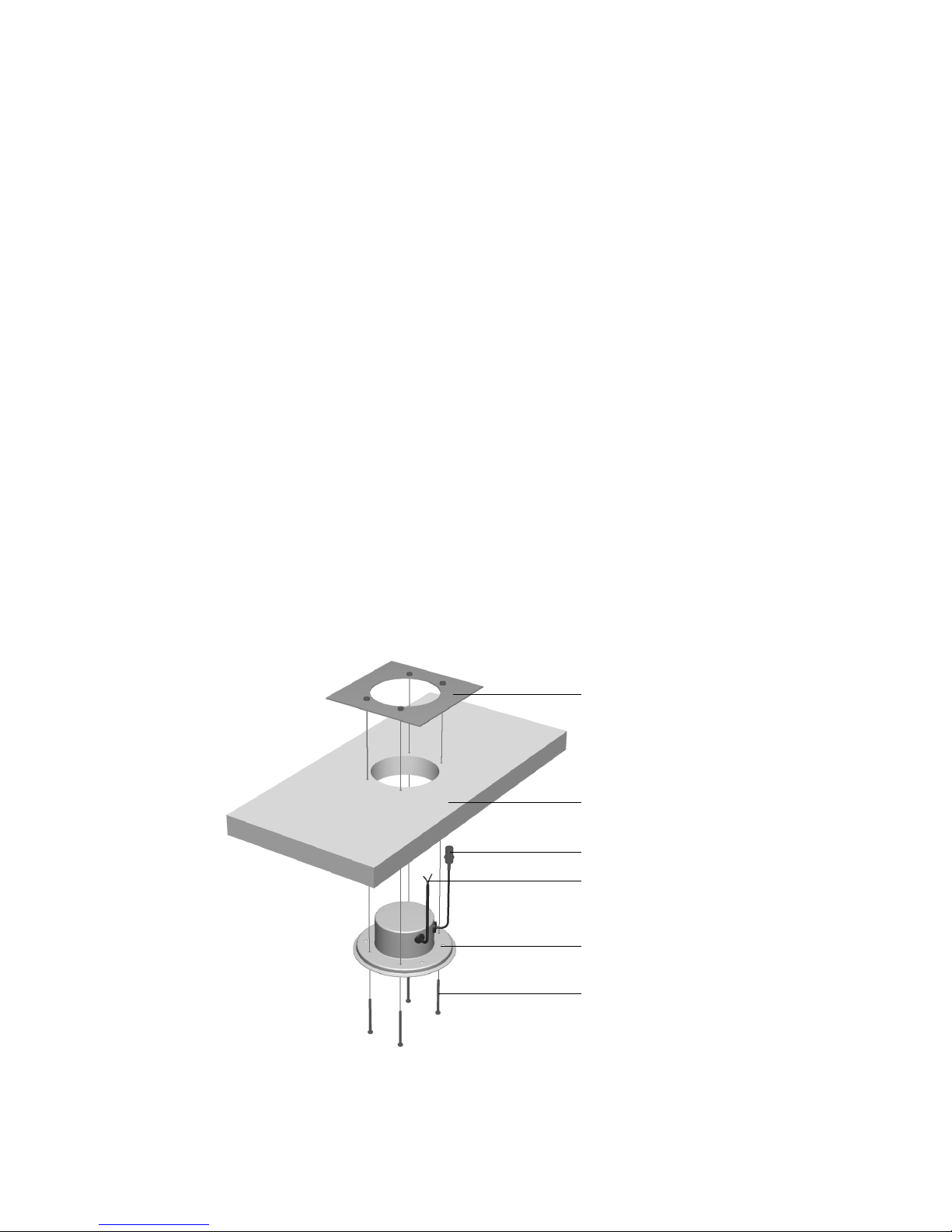
Figure 4 Wall/Ceiling Mount Installation
Backing plate
(optional)
Mounting panel
Video output
Power input
V25 base
#6-32 mounting
screws (x4)
6
Document 920.0090 Rev 3.00 April 16, 2002
 Loading...