

Page 1

SILENTWIND Pro – User Manual
SILENTWIND
12V / 24V /48V
www.SilentWindgenerator.com
March 2019
Page 2

2
Silentwind Pro – User Manual
March 2019
Page 3

3
Silentwind Pro – User Manual
March 2019
Index
INDEX .................................................................................................................................................................... 3
1. PRECAUTIONS ............................................................................................................................................... 6
2. PRESENTATION .............................................................................................................................................. 7
3. TECHNICAL DATA ........................................................................................................................................... 8
3.1 SILENTWIND PRO – ELECTRICAL DATA .......................................................................................................... 8
3.3 HYBRID BOOST CHARGE CONTROLLER – ELECTRICAL DATA ......................................................................... 8
3.4 HYBRID BOOST CHARGE CONTROLLER - MECHANICAL DATA ....................................................................... 8
3.5 POWER CURVE ............................................................................................................................................. 9
3.6 DIMENSIONS .............................................................................................................................................. 10
3.7 PACKAGE CONTENTS .................................................................................................................................. 11
4. SAFETY PRECAUTIONS ................................................................................................................................. 12
4.1 MECHANICAL RISCS .................................................................................................................................... 12
4.2 ELECTRICAL RISKS ....................................................................................................................................... 12
4.3 INSTALLATION RISKS .................................................................................................................................. 13
4.4 WHEN WORKING ON THE SYSTEM ............................................................................................................. 13
4.5 DISSASEMBLY SEQUENCE ........................................................................................................................... 13
5. INSTALLATION ............................................................................................................................................. 14
5.1 RECOMMENDATIONS ................................................................................................................................ 14
5.1.1 SITE ........................................................................................................................................................ 14
5.1.2 THE MAST .............................................................................................................................................. 15
5.1.3 THE BODY ............................................................................................................................................... 16
5.1.4 ELECTRICAL INSTALLATION .................................................................................................................... 16
5.2 REQUIRED TOOLS AND EQUIPMENT .......................................................................................................... 16
5.3 CABLES AND FUSES ..................................................................................................................................... 17
5.4 MECHANICAL INSTALLATION ..................................................................................................................... 18
5.4.1 INSTALLATION ON LAND ........................................................................................................................ 18
5.4.2 INSTALLATION ON A VESSEL .................................................................................................................. 18
5.4.3 SILENTWIND Pro ASEMBLY .................................................................................................................... 20
5.5 ELECTRICAL INSTALLATION ........................................................................................................................ 22
5.6 CHECK LIST ................................................................................................................................................. 24
6. OPERATION ................................................................................................................................................. 25
7. MAINTENANCE ............................................................................................................................................ 26
7.1 ROTOR BLADES ........................................................................................................................................... 26
7.2 SCREWS ...................................................................................................................................................... 26
7.3 BEARING AND GASKETS ..................................................................................................................................... 26
7.4 CORROSION PROTECTION ................................................................................................................................. 26
7.5 MOUNTING SYSTEM .......................................................................................................................................... 26
7.6 ELECTRICAL SYSTEM .......................................................................................................................................... 26
8. VIDEO LINKS ................................................................................................................................................ 27
9. FAQ ............................................................................................................................................................. 27
10. TROUBLESHOTTING ................................................................................................................................. 29
10.1 SILENTWIND PRO DOES NOT START OR IT’S ROTATING SLOWLY ................................................................ 29
10.2 BATTERY IS NOT FULLY CHARGED ............................................................................................................... 30
10.3 SILENTWIND PRO DOES NOT CHARGE ......................................................................................................... 30
11 WARRANTY ................................................................................................................................................. 31
11.1 DISCLAIMER OF WARRANTY ....................................................................................................................... 32
11.2 WARRANTY CARD ....................................................................................................................................... 33
11.3 AFTER-SALES SERVICE ................................................................................................................................ 33
12 QUICK INSTALLATION QUICK GUIDE ............................................................................................................ 34
Page 4

4
Silentwind Pro – User Manual
March 2019
Page 5

5
Silentwind Pro – User Manual
March 2019
Congratulation! You have just purchased the new generation of wind generators.
SILENTWIND Pro
SAFE – QUIET – EFFICIENT
SILENTWIND Pro is constructed of the highest quality material and has been thoroughly inspected.
The Warranty Terms are described in a chapter of this manual. For traceability under the warranty, please
register the SILENTWIND Pro on our website: www.silentwindgenerator.com
Registering your SILENTWIND Pro has the following benefits:
- Confirmation of your ownership and safety notifications: by keeping a record of your registration,
we will be able to trace your product and contact you quickly if necessary;
- Product information a new: choose to be among the first to hear about our latest product, helpful
advice or product developments
If you have any questions or comments, do not hesitate contact us:
Rulis Eléctrica Lda
Loteamento Industrial de Linhares, Lote 19
PT-4805-486 Santo Estevão de Briteiros / Guimarães
Portugal
Phone: 00351-253-572763
Fax: 00351-253-572764
E-mail: [email protected]
Business Hours:
Monday to Friday: from 8h00 to17h00 GMT + 0:00
Welcome to Silentwind family!
The CE marking is a mandatory compliance requirement in EMEA and the UK and although it is self-certified, testing
and evidence to support that testing is preferred from an independent test house.
Machinery Directive 2006/42/EC, Low Voltage Directive 2004/95/EC, Electromagnetic Combability Directive
2004/108/EC. The report and the declaration of conformity are available for inspection on request.
Page 6

6
Silentwind Pro – User Manual
March 2019
1. PRECAUTIONS
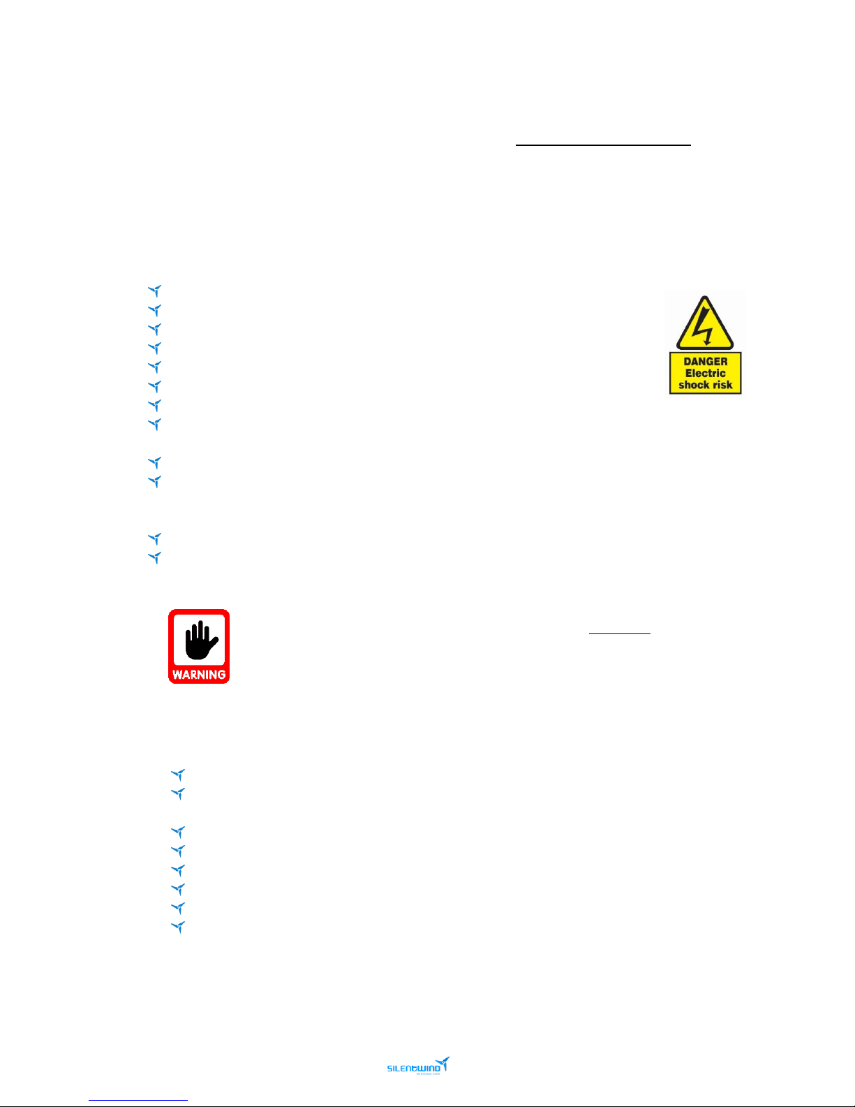
➢ Please note this manual is part of the SILENTWIND Pro and must be read carefully.
➢ Please study the information thoroughly before starting the installation.
➢ This manual should always be kept near the SILENTWIND Pro.
➢ Always download the up-to-date manuals. Manuals may change without prior notice.
In this manual, you will see the following icons:
Pay attention. Very important.
High risk. Injury.
Damage to equipment may result if not heeded.
Electrical warning sign.
Major risk, severe injury or dead.
Major risk, severe injury or dead.
Page 7
7
Silentwind Pro – User Manual
March 2019
2. PRESENTATION
The SILENTWIND Pro features:
Aerodynamic design from aircraft-engineering
Lightweight
Very good start-up performance due to low cogging torque
Low noise
Easy installation
Does not have any inbuilt control electronics, which means that there is hardly any
maintenance work on the generator itself
The Blades are carbon fiber hand laminated, UV-resistant, successfully tested on wind
tunnels at hurricane speed of 122km/h
External Hybrid Boost Charge Controller for wind and solar energy with multi-function display
and integrated electronic stop switch
Durable and low maintenance by external Hybrid Boost Charge Controller and high-quality
components
It is possible to connect several SILENTWIND Pro if your demand is high. As noise emission is very low, you
can operate in residential areas and on vessels without annoying your neighbors.
The SILENTWIND Pro can be used in universal applications on low, middle and high winds:
Any location without an electricity grid connection.
Research units.
Traffic management system.
Emergency systems.
Street lamps.
Billboard illumination.
Project in developing countries.
Wireless LAN access points.
Holiday homes with inverters for independent provision of electricity.
Charge the batteries of an electric vehicle.
Page 8

8
Silentwind Pro – User Manual
March 2019
3. TECHNICAL DATA
3.1 SILENTWIND Pro – ELECTRICAL DATA
TECHNICAL DATAType of generator
Permanent magnet generator, 3 phases, AC
Rated voltage*
12 VDC / 24 VDC / 48 VDC
Rated power
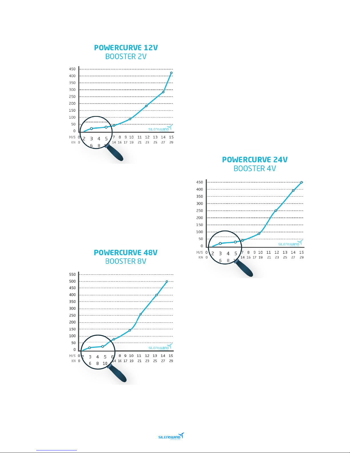
420 Watt / 450 Watt / 500 Watt
Rated peak power at
14.5 m/s
Start up speed
2 m/s
Start of charging
2.2 m/s
* Your battery set must match the SILENTWIND Pro rated voltage.
3.2 SILENTWIND Pro – MECHANICAL DATA
Safety test in wind tunnel
122km/h without failure
Rotor diameter
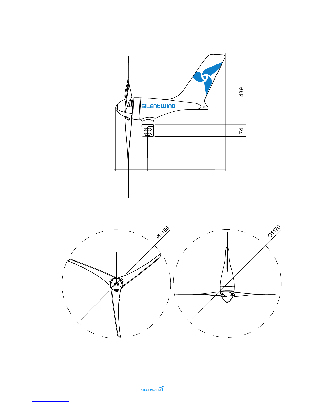
1.15 m
Number of blades
3
Weight of blades
150 g / blade
Material of blades
Carbon fiber, hand laminated
RPM range
550 – 1700 rpm
Weight
6.8 kg (Generator)
Package dimensions
780 x 400 x 210 mm
Package weight
10 kg
Color
White RAL 9010, powder coated
3.3 MPPT HYBRID BOOST CHARGE CONTROLLER – ELECTRICAL DATA
System voltage*
12 VDC / 24 VDC / 48 VDC
Max. power input wind generator
600 Watt
Max. current input wind generator
40 A / 30 A / 15 A
Max. power input solar
300 Watt
Max. current input solar
20 A / 10 A / 5 A
Max. open circuit voltage input of the solar panel
48 VDC / 48 VDC / 96 VDC
LCD + LED displays
W, A, V/Ah, kWh, Ah
* Maximum voltage adjustable for acid, gel and AGM batteries
3.4 MPPT HYBRID BOOST CHARGE CONTROLLER - MECHANICAL DATA
Weight
2.30 kg
Package dimensions
220 x 150 x 83 mm
Cover protection class
IP52
Page 9
9
Silentwind Pro – User Manual
March 2019
3.5 POWER CURVE
Page 10
10
Silentwind Pro – User Manual
March 2019
3.6 DIMENSIONS
Page 11
11
Silentwind Pro – User Manual
March 2019
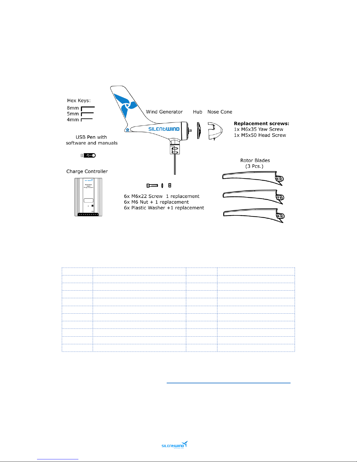
3.7 PACKAGE CONTENTS
Please check if all enclosed parts are correct.
Packing List
Item
Description
Quantity
Order number
1
Generator body, powder coated
1
SW501
2
Hub
1
SW105
3
Nose Cone 1 SW101
4
Blades 3 SW103
5
Hybrid Boost Charge Controller
1
SW701
6
Set of screws 1 -
7
Hex Key 4mm 1 SW901
8
Hex Key 5mm 1 SW902
9
Hex Key 8mm 1 SW903
10
Pen drive (*) 1 -
(*) With Instruction Manuals – SILENTWIND Pro
Video Link - Silentwind Package Contents: https://www.youtube.com/watch?v=pLuSNRxI7nE
Page 12
12
Silentwind Pro – User Manual
March 2019
4. SAFETY PRECAUTIONS
Our primary concern when we have developed the SILENTWIND Pro was your safety. The information
provided is to ensure your safety during mounting, operation, and in case of trouble.
If you have any additional questions, please contact us.
4.1 MECHANICAL RISCS
The blades are produced in carbon fiber and their aerodynamic shape have very sharp edges which
can cause severe injury in high wind conditions. For several reasons, the turning rotor system must
be handled with caution. You cannot see the end of the blades in high wind speeds, so you may not
recognize the inherent danger.
Always keep clear of the turning blades in all circumstances.
Never try to touch the turning rotor system.
Never try to stop the turning rotor system manually.
Blades can break due to ropes or other objects touching them in very strong winds
If one of the blades is damaged, immediately activate the BRAKE function using the stop
switch on Hybrid Boost Charge Controller. If one of the blades is damaged, the rotor system
will be out of balance which may be a risk for the whole mounting construction.
4.2 ELECTRICAL RISKS
A running SILENTWIND Pro can generate a considerable AC voltage and current per phase. High
voltage and current can cause serious injury and fire if you do not pay attention to safety.
Only person with appropriate technical skills and knowledge should carry out
the electrical installation.
Caution is recommended for people with cardiac pacemakers.
Never touch the open end of the wires.
The current when charging the batteries can reach more than 30A.
Careful to never short-circuit the battery.
Always provide enough ventilation for batteries.
To reduce installation problems, keep wire run as short as possible and mount all system
components as close to the batteries as possible.
Page 13
13
Silentwind Pro – User Manual
March 2019
4.3 INSTALLATION RISKS
Please observe the following precaution during SILENTWIND Pro installation:
Do not install on a windy day.
Only use or build mounting/support system that can handle the load of the SILENTWIND Pro and
the blast pressure of the wind in any condition.
Make sure that nobody is close to the mast.
Before a storm the SILENTWIND Pro should be manually stopped with the stop switch on the
Hybrid Boost Charge Controller and one rotor blade must be fixed to the mast due to the risk of
damage by flying objects.
4.4 WHEN WORKING ON THE SYSTEM
Never work on the system during charging. The current is very high.
Major risk, severe injury or dead. Risk of fire.
Stop the system first by following the below sequence!
4.5 DISSASEMBLY SEQUENCE
1
st
Brake the wind generator. Tie the blades with a rope if possible.
2nd Disconnect the SILENTWIND Pro . If you have not tied the rope to the blades, to avoid
risks, once you remove the 3 wires from the generator please put at least 2 wires from
the generator together to cause a short circuit and slow down the rotation of the blades.
Use a tape to keep it on short-circuit.
3rd If you are using solar panels, cover them and disconnect them from the charge
controller.
4th Disconnect Battery. This is very important. Otherwise the Hybrid Boost Charge
controller will be damaged.
To assemble to equipment, follow the reverse order.
Page 14
14
Silentwind Pro – User Manual
March 2019
5. INSTALLATION
Before mounting the SILENTWIND Pro find a suitable position for the wind. The ideal position is when the
wind flows without any obstacles in the surroundings.
Please note that the SILENTWIND Pro can never be fully efficient if it is not mounted in the prevailing wind
direction or distracted by obstructions. Therefore, it is important to find a position without obstructions.
5.1 RECOMMENDATIONS
5.1.1 SITE
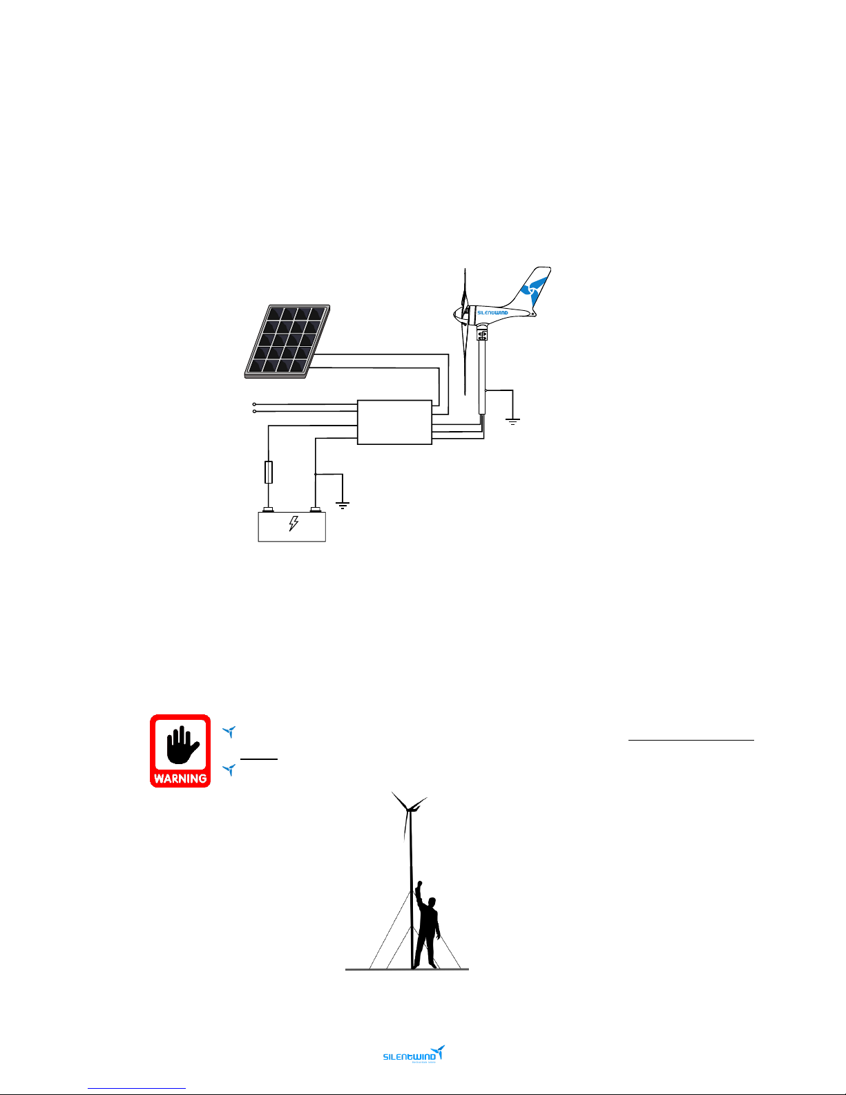
Make sure that you install the SILENTWIND Pro in a position where nobody can touch the
blades.
On a vessel, always ensure it is mounted at an enough height above the deck.
Further info on the following chapters.
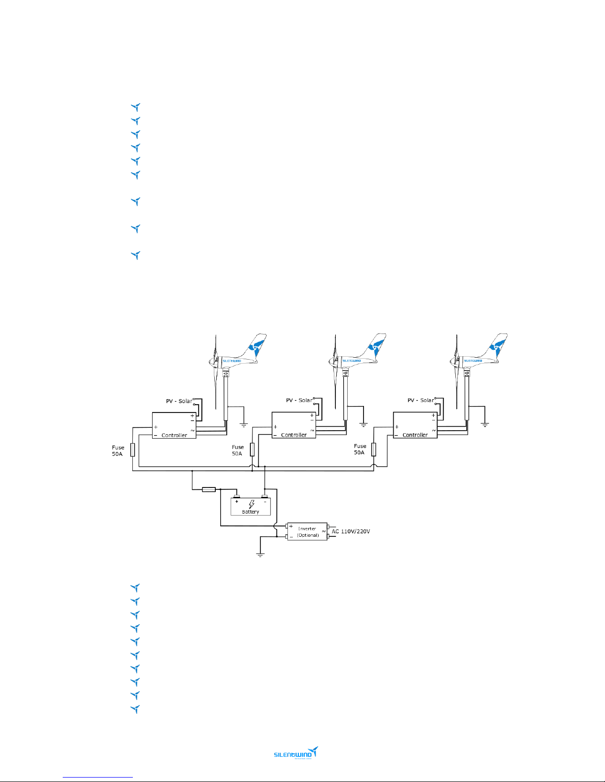
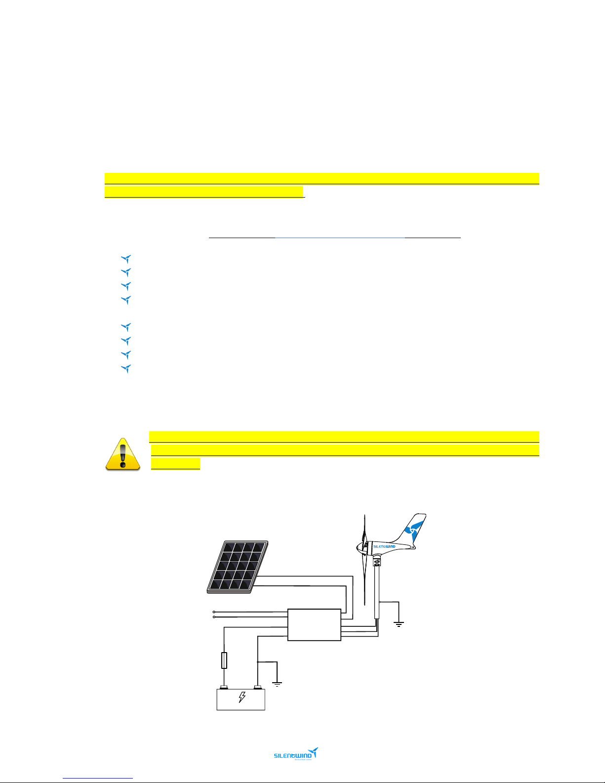
Electrical assembly illustration
Page 15
15
Silentwind Pro – User Manual
March 2019
5.1.2 THE MAST
The mast is a separated product and it is considered a third-party component.
On vessels, look for the advice on your vessel manufacturer or on your vessel maintenance company.
On land use, look for advice of a structural engineer.
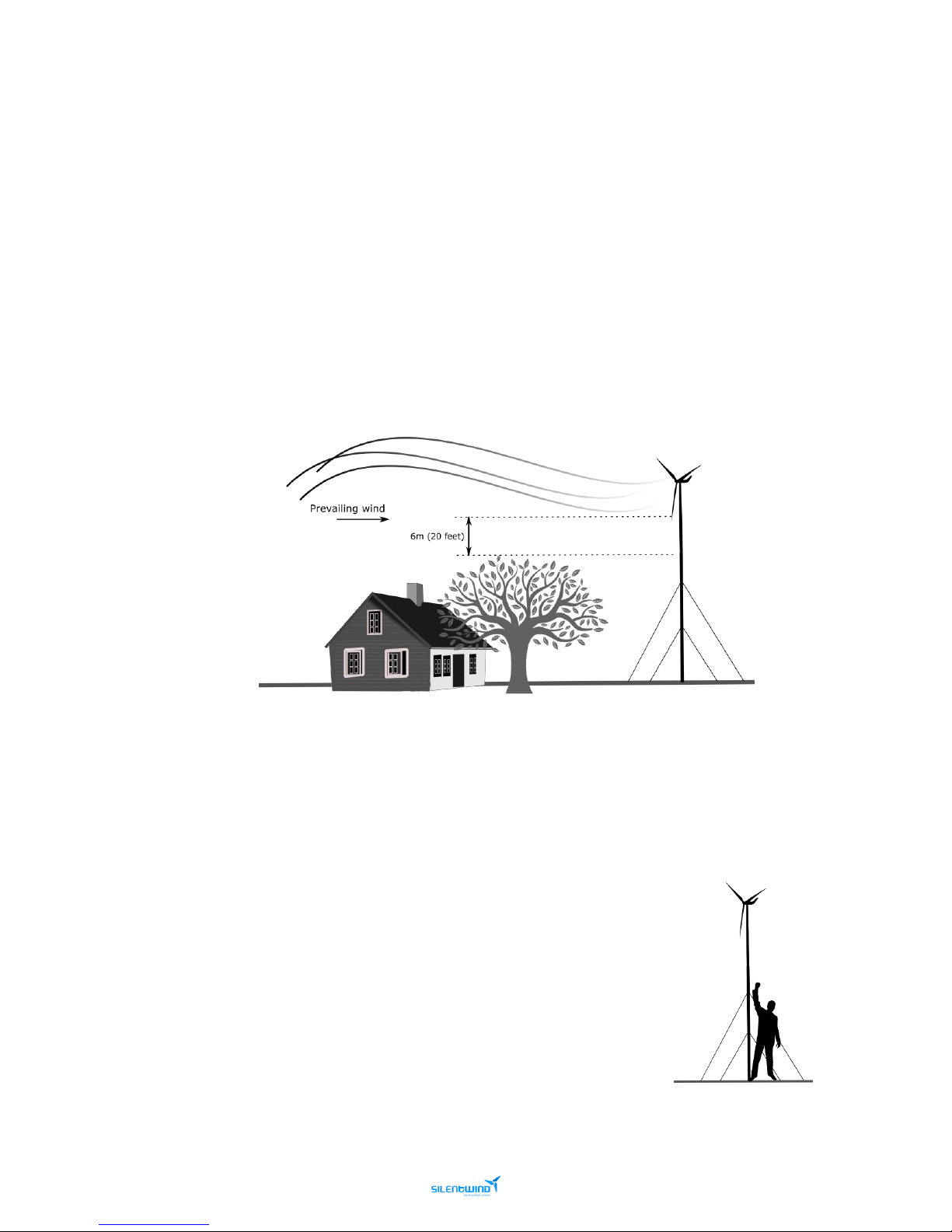
The mast should be as short as possible but high enough that the blades do not interfere with any
objects and nobody can get hit by the blades. Usually at a height of 3 meters. Make sure that
SILENTWIND Pro gets “clean air”.
The mast must be well secured so that it is safe in strong winds and in adverse sea conditions.
The mast and the mast stays should be assembled in such a way that vibration will be not magnified.
The SILENTWIND Pro is a lightweight equipment but some precautions must be followed.
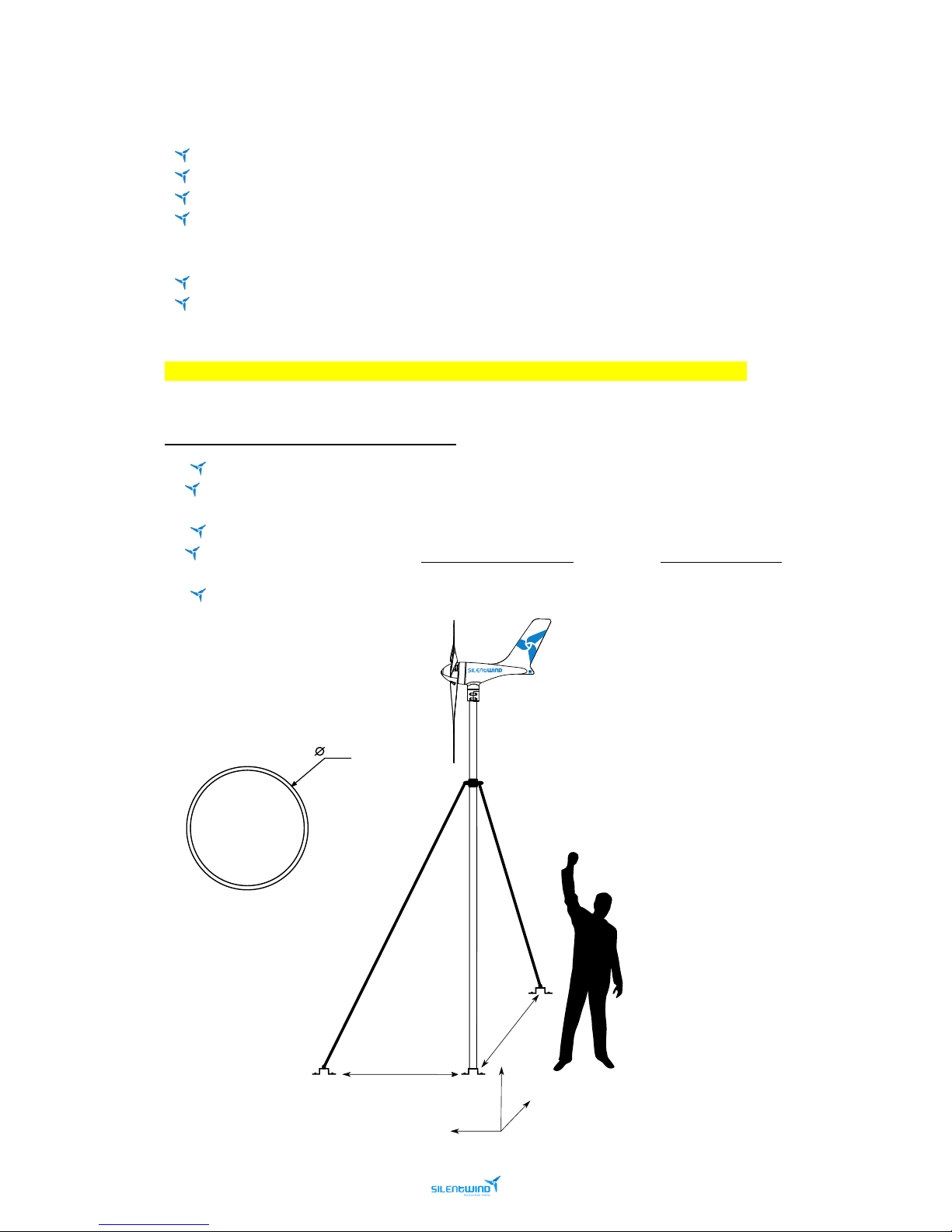
MINIMUM RECCOMENDED SPECIFICATIONS:
For marine applications, choose preferentially a marine grade stainless steel mast.
Aluminum masts are not recommended. Use aluminum masts only manufactured by certified
mast manufacturers.
The recommended diameters are 48 or 50mm.
The mast profile on steel, must not be less than 1,5mm thickness on 3m high maximum. The mast
must be anchored with rigid rods or steel cables (see the example below).
Use the proper anchorage.
Page 16
16
Silentwind Pro – User Manual
March 2019
5.1.3 THE BODY
To avoid any damage to the powder coated aluminum housing please touch up any scratches, chipping of
paint work during installation. Sea water will penetrate the scratches and peel off the paint slowly.
As an additional precaution against electrolytic corrosion between dissimilar metals, you can use
“Duralac” or “Tefgel” on the 4 yaw bearing mast bolts/nuts.
5.1.4 ELECTRICAL INSTALLATION
Make sure all wires are placed in the correct position so that damage cannot occur.
The 3 AC cables need to have the same cross section and the correct mm²/AWG.
A damaged cable is a severe safety risk.
Wires with inadequate cross section can cause fire.
Make sure the electrical connections (crimping) are done 100%.
Any voltage drops can influence the control of brake functions.
Use tinned copper cables for marine installations.
When connecting Hybrid Boost Charge Controller to the battery, sparks can occur.
A short circuit is to be avoided.
Always ensure enough ventilation in battery location.
If the Hybrid Boost Charge Controller is not easily accessible, you can use a remote brake switch
connect with the external stop switch to the Hybrid Boost Charge Controller. You can choose the type
of stop switch suitable to your instrument panel.
Connect the mast or support to the ship´s grounding system whenever possible.
Check your battery specifications carefully. Read the battery manual if available.
If you are not qualified to perform electrical installations, don’t do it.
Work safely.
To execute the tasks, use the proper tools.
5.2 REQUIRED TOOLS AND EQUIPMENT
Mast with 48mm to 50mm diameter.
Extension cables to connect the three AC SILENTWIND Pro phases to the Hybrid Boost Charge
Controller.
Connectors for the three-phase cables and crimp plier
Red and black cable to connect the Hybrid Boost Charge Controller to the battery.
Joint connector for battery cable.
Fuse.
Measure tape.
A set of Allen keys is provided to assist with the installation of SILENTWIND Pro.
NOTE: Other tools might be needed. Please plan all steps carefully.
Page 17
17
Silentwind Pro – User Manual
March 2019
5.3 CABLES AND FUSES
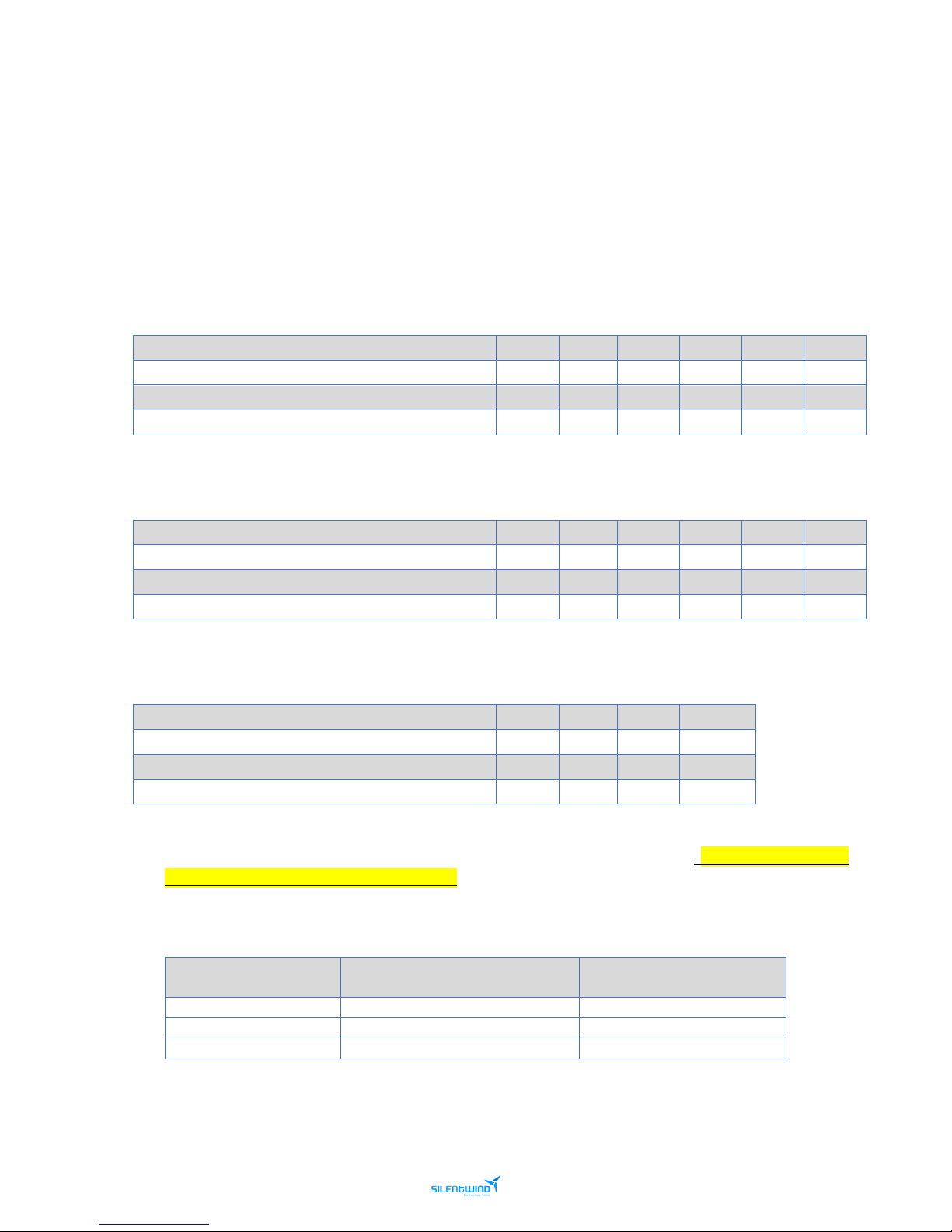
The cross section of the wires required depends on their length and the rated voltage of your system.
Select the location of the mast and measure the distance from the mast top to the battery. Select the
minimum cross section required in the basis of the following tables. The 3 AC cables need to have the
same cross section.
System voltage 12 Volt
Distance from wind generator to the charge controller (m)
0 - 9
10 - 19
20 - 29
30 - 44
45 - 69
70 - 110
Cable cross section mm2 - AWG
6 – 10
10 – 8
16 – 6
25 – 4
35 – 2
50 – 1
Distance from the charge controller to the battery (m)
0 – 9
10 – 19
20 - 29
30 – 44
45 - 69
70 - 110
Cable cross section mm2 - AWG
16 - 6
24 - 4
35 - 2 - -
-
System voltage 24 Volt
Distance from wind generator to the charge controller (m)
0 - 9
10 - 19
20 - 29
30 - 44
45 - 69
70 - 110
Cable cross section mm2 - AWG
2.5 - 14
4 - 12
6 - 10
10 - 8
16 - 6
25 - 4
Distance from the charge controller to the battery (m)
0 – 9
10 – 19
20 - 29
30 – 44
45 - 69
70 - 110
Cable cross section mm2 - AWG
16 - 6
25 - 4
35 - 2 - -
-
System voltage 48 Volt
Distance from wind generator to the charge controller (m)
0 - 29
30 - 79
80 - 99
100 - 150
Cable cross section mm2 - AWG
2.5 - 14
4 - 12
6 - 10
10 - 8
Distance from the charge controller to the battery (m)
0 – 29
30 – 69
70 - 99
100 - 150
Cable cross section mm2 - AWG
4 - 12
4 - 12
10 - 8
16 - 6
For protection against high voltage spikes and/or an accidental short-circuit event, fuses must be installed
in the positive (red) wires close to the battery. The required value of the fuse depends on the rated current
of the SILENTWIND Pro and solar panels connected to the Hybrid Boost Charge Controller. Considering
the maximum value of currents, we recommend:
Silentwind Pro
Max Current (A)
(SILENTWIND Pro + Solar Panel)
Fuse (A)
12V
40 + 20
50 + 25
24V
20 + 10
30 + 15
48V
10 + 5
20 + 10
Page 18
18
Silentwind Pro – User Manual
March 2019
5.4 MECHANICAL INSTALLATION
5.4.1 INSTALLATION ON LAND
The height depends on the distraction of the wind by surrounding objects. You can simply test this
fixing 3 meters long by 4 cm wide strip of plastic at the top of 4 meters (or longer) pole. You can use
a second strip at 2 meters height.
If the upper plastic strip flows horizontally or up to 30 degrees from the horizontal you have found
the suitable position. In case the plastic strip shows more than 30 degrees from the horizontal or
turns around the mast, the position is unsuitable. This test should be carried out at moderate wind
conditions and must be considered as an additional information only.
We recommend doing several tests for an optimal site assessment. However, you do not need to
do this test if the SILENTWIND Pro is mounted far away from obstructions. You can also get help
from specialists on a small wind generators.
Having found a suitable position, an appropriate mast with suitable hardware must be chosen. The outer
mast diameter must be between 48mm to 50mm and it should be made of stainless steel or aluminum*.
Please also consider possible future maintenance work.
Earthing of the mast is highly recommended. On vessels you can use the central earthing point for mast
and engine. Ask a specialist for advice.
*Please check the aluminum mast maximum load with the manufacturer.
5.4.2 INSTALLATION ON A VESSEL
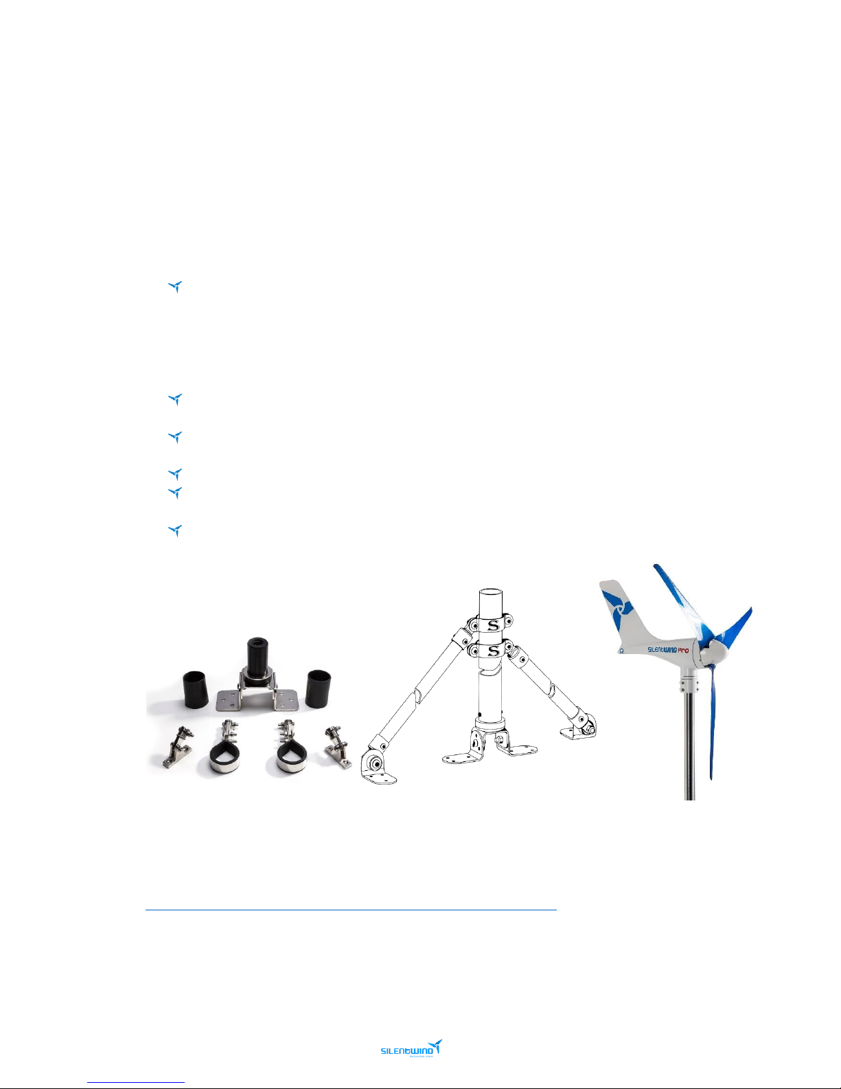
The assembly height must be chosen in a way that no member of the
crew is endangered by the rotor blades (around 3 meters). The
mechanical fixation of the mast foot must withstand the mechanical
loads occurring specially in rough sea conditions. We recommend
additional rigging to the sea rail or the deck of the ship.
Please consult your vessel manufacturer or your vessel maintenance
partner for advice.
Page 19
19
Silentwind Pro – User Manual
March 2019
Vessel/motorhomes equipped with wind generators typically have a dedicated mast used as the mounting
post for the wind generator.
Vibrations generated by all wind generators will be transferred down into the vessels hull or the
motorhomes walls via the mast and the fittings. These are called “harmonics”.
Therefore, how the mast is fitted to the deck/motorhomes is one of the most important parts of the
installation.
In order to eliminate harmonics and get best performance out of the SILENTWIND Pro we recommend the
following when installing on a vessel/motorhome:
Do not position SILENTWIND Pro in line with a backstay or centered position on your stern. It
needs to be positioned above the Bimini, coach house or any other construction. To work most
efficiently and with the lowest noise emission all wind generators need “clean air”. During the
wind tunnel testing it was clearly proven that any turbulence will decrease the SILENTWIND Pro
performance. The anemometer on a vessel is usually on a different Hight of the wind generator,
the windspeed shown will not be the same as on the wind generator. Please take this is account.
Avoid attaching the mast on any existing structure; for instance, a frame which holds solar panels,
Biminis, rail fitting, etc.
Use rubber inserts between deck and mast base, rubber washer for screws or bolts to remove any
latent vibrations before entering the hull/motorhome.
Use the supplied rubber insert between the SILENTWIND Pro and the mast.
All brackets, like mast clamps, need rubber strip insertions (3-4mm thickness and of medium
density) between parts.
An upper mast bracket should be installed approximately 20 cm below the lowest part of the
blades tip to stabilize the mast.
Once the mast is mounted you can start the installation of the SILENTWIND Pro.
Video Link – Silentwind Scantrut Mas Assembly:
https://www.youtube.com/watch?time_continue=1&v=0dVJIwbwAWY
Page 20
20
Silentwind Pro – User Manual
March 2019
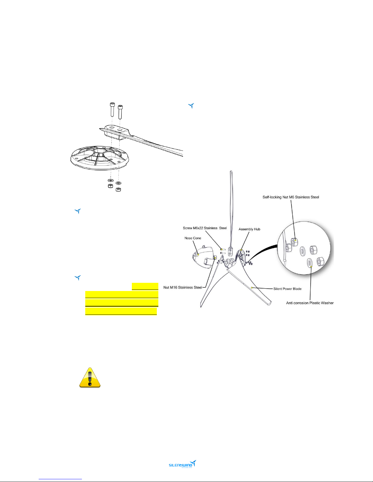
5.4.3 SILENTWIND Pro ASEMBLY
1ST - CONNECT THE 3 BLADES TO THE ASSEMBLY HUB WITH THE ENCLOSED SCREWS
The fastening torque is 7-8 Nm equivalent to a
weight of 7-8kg on a 10 cm long lever arm, upright to the
lever arm. If the fastening torque is too high, this will
destroy or damage the blades. If the fastening torque is
not high enough, the blades can get lose. A wrong
fastening torque is a considerable safety risk.
Move each rotor blade in
running direction towards
the edge of the blade guide
of the hub. The running
direction is clockwise
looking from the front.
Before the final tightening of
the blade screws, make sure
that the distance between
the blade tips is the same, in
order to avoid vibrations.
Take a measuring tape and measure the distance from all three tips of the blades and adjust
accordingly (Approximately 990mm ± 5mm tolerance). The blades have been balanced statically
and dynamically.
An incorrect tightening torque represents a significant security risk. Regularly control
the fixation of the blades!
The enclosed nylon discs protect against electrolytic corrosion.
Page 21
21
Silentwind Pro – User Manual
March 2019
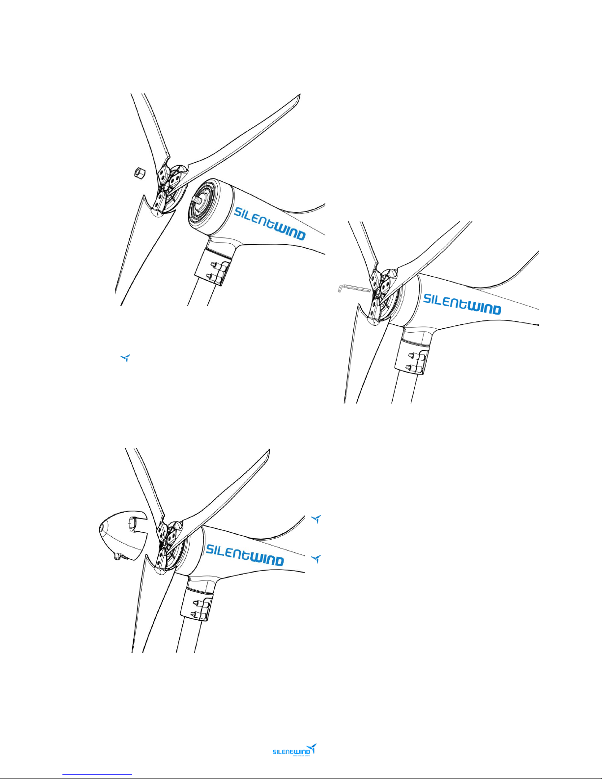
2nd FIX THE SET TO THE SILENTWIND Pro SHAFT WITH THE ENCLOSED SCREW NUT
(use the enclosed hexagon socket screw key).
The M16 Nut and the Hub is marked. The
arrow on the central nut should point towards
SILENTWIND Pro head. Do not over tighten
the central nut.
3rd SNAP THE NOSE CONE INTO PLACE ON THE ASSEMBLY
HUB
If possible, it is best to attach the hub with the blades
to the shaft at the very end of the mounting procedure.
After a week or so check the central nut which
connects rotor hub to shaft for tightness. Also check the 6
bolts which fix the blades to the hub.
Page 22
22
Silentwind Pro – User Manual
March 2019
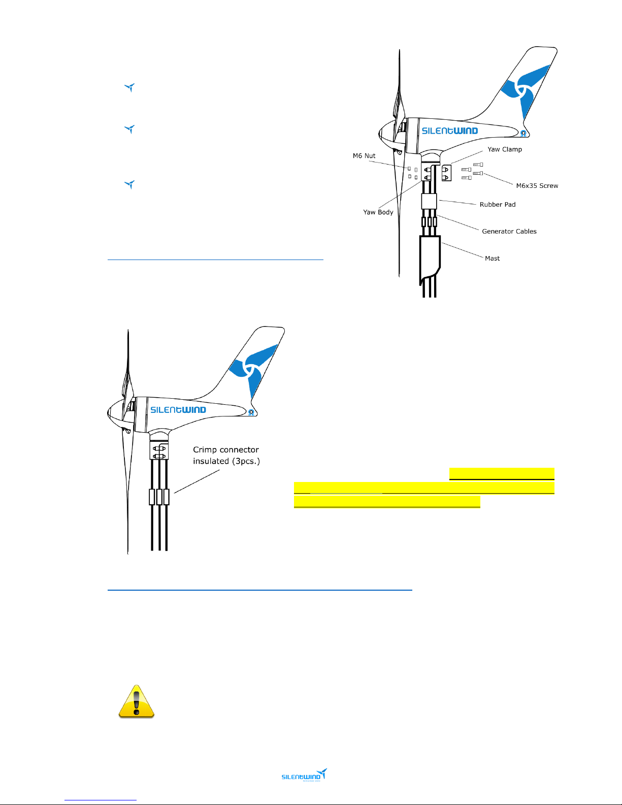
4th MOUNT THE SILENTWIND ON THE MAST
Fix the 4 hexagon screws to the yaw clamp after
inserting the rubber pad.
When tightening the screws take care for a
uniform, circumferential tightening of the 4
screws.
The tightening should be made with small
increments in order to avoid damaging the
marine grade painting.
Video Link - Silentwind Blade Assembly:
https://www.youtube.com/watch?v=0avf_y2U3gY
5.5 ELECTRICAL INSTALLATION
Make an extension of the 3 cables AC, using a crimp connector
insulated will be necessary since the SILENTWIND Pro will be
fixed in the mast and the Hybrid Boost Charge Controller will
not be fixed in the same place.
If there is enough wind speed when connecting SILENTWIND
Pro, this will immediately generate electric power at the end
of the 3 AC-wires without being connected to the Hybrid
Boost Charge Controller. Therefore, we recommend blocking
the SILENTWIND Pro blades with a rope before connecting the
wires to the Hybrid Boost Charge Controller.
Video Link - Silentwind Cable Connection:
https://www.youtube.com/watch?time_continue=1&v=1W4HlPHQ_C4
Connect insulating screw joints in the end of the wires coming from the battery. In case you do not use
the connecting wires, we recommend the use of crimp type cable sockets to connect your wires directly
to the Hybrid Boost Charge Controller.
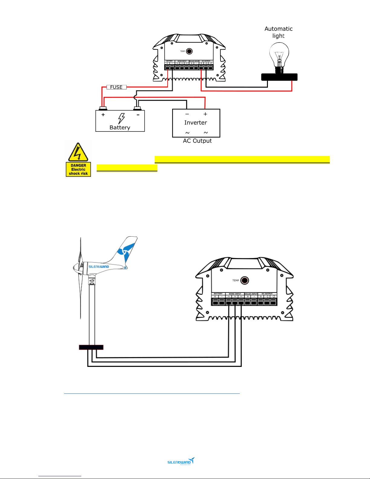
Install a fuse between the Hybrid Boost Charge Controller and the battery positive pole, as
close as possible to the battery.
Page 23
23
Silentwind Pro – User Manual
March 2019
It’s very important that you first connect the Hybrid Boost Charge Controller to the battery
with the right polarity. The confusion of plus (red) and minus (black) will destroy your Hybrid
Boost Charge Controller.
After the connection of the battery you can connect to SILENTWIND Pro, the solar panel and if required a
load output with maximum 10A.
The 3 AC output wires must be connected to the 3-screw terminal on the back of the Hybrid Boost Charge
Controller. In a 3 phase AC system the connection order/polarity does not matter.
Video Link - Silentwind Charge Controller Installation:
https://www.youtube.com/watch?time_continue=5&v=DS5oi9-2Hbk
Page 24

24
Silentwind Pro – User Manual
March 2019
5.6 CHECK LIST
Before getting you SILENTWIND Pro started, check the correct mounting and installation according to the
following check list:
Mast
The mounting system can handle with strong wind conditions?
The mounting is assembled that vibration will not magnified?
Rubbers were used in strips insertions?
Mast bracket was installed?
Body
Any damage to the power coated aluminum?
Yaw Shaft
The rubber pad is fixed correctly?
Blades
Do not interfere with any objects and nobody can get hit them?
The distance between the blades is the same?
Assembly Hub
The assembly hub was fixed to the SILENTWIND Pro shaft?
The central screw nut was fastened with 30Nm?
Electric Installation
Enough ventilation is provided?
The electrical connections (crimping) were done correctly?
All wires are correctly placed?
The wires have the correctly cross section: SILENTWIND Pro and battery?
The fuse was installed between the Hybrid Boost Charge Controller and the battery?
Hybrid Boost Charge Controller
Fastened securely to the mounting location?
All screw terminals are firmly tightened?
Page 25
25
Silentwind Pro – User Manual
March 2019
6. OPERATION
If there’s enough wind speed, SILENTWIND Pro will start charging. You can control this on the LCD display
of the Hybrid Boost Charge Controller or from your smartphone or tablet using SILENTWIND Pro APP that
is available for Android and IOS devices.
The settings to operate the Hybrid Boost Charge Controller and SILENTWIND Pro are done through APP
or directly on the charge controller. The Hybrid Boost Charge Controllers are parametrized by default with
standard settings.
You must check all the parameters by yourself. Wrong settings can permanently damage your batteries,
your charge controller and your wind generator.
The Hybrid Boost Charge Controller must be adjusted according the type of battery and according to your
individual requirements. Please read the Hybrid Boost Charge Controller user manual.
End of charge Voltage – Batteries maximum voltage
Overvoltage – Load Output 1 and 2 Voltage protection
Low Wind Boost – set the boost to achieve an earlier start of charging in to the batteries
Storm Brake – Maximum amperage allowed. It will limit the maximum rpm speed and prevents
overheating.
Under Voltage Switch Off – To avoid fast discharging, below this value the Outputs are turned Off
Under Voltage Recovery On – Above this value, the Outputs are turned On
Solar Switch Off – Above this value, it will turn the Outputs Off
Solar Switch On – Below this value, it will turn the Outputs On
If the break adjustment and charge cut off voltage is reached, the SILENTWIND Pro will stop for
approximately 10 minutes.
If the capacity of the batteries is less than 150 Ah, or old batteries that have lost their original
capacity, the point of max. voltage can be reached very fast although the battery is not fully
charged yet. In this case it can be useful to connect an electric consumer to the Load-output,
as this will reduce the voltage and thus prevent that the break mode is activated too early.
Page 26

26
Silentwind Pro – User Manual
March 2019
7. MAINTENANCE
Your SILENTWIND Pro was manufactured for long term use without any maintenance. However, simple
and regular verification ensure the necessary security.
Before starting the verification, make sure the blades are stopped and the battery is not
connected to the Hybrid Boost Charge Controller. Please follow the DISSASEMBLY SEQUENCE
chapter.
The following verification should be carried out:
7.1 ROTOR BLADES
Check if the blades show damages like broken edges, damaged surface or cracks. If you notice any
damage, the SILENTWIND Pro must be immediately stopped.
7.2 SCREWS
Check that all accessible screws are correctly fixed. Especially the hexagon screws from the hub, the
central shaft nut and the fixing of the mast must be checked.
7.3 BEARING AND GASKETS
The bearing of the SILENTWIND Pro shaft and the yaw bearing of the shaft are permanently lubricated.
Check these bearings for free movement, or noise. Damaged bearing must be replaced.
7.4 CORROSION PROTECTION
If the outer layer is damaged, there is a risk of corrosion. Paint these spots with suitable varnish (RAL9010).
7.5 MOUNTING SYSTEM
Check the mounting system for stability and absence of loose screws (if applicable).
7.6 ELECTRICAL SYSTEM
Check if all connections are properly fixed and not corroded. If there’s corrosion it must be removed and
treated with contact spray.
Give special attention to the battery connections: they must be cleaned and greased with Vaseline. Check
the batteries instructions from the manufacturer and check which how to perform the maintenance
correctly. If more than one battery is used check if all batteries have the same capacity and state of charge.
Maintenance Part
Frequency
Rotor Blades
3 months (*)
Screws
12 months
Bearing and gaskets
12 months
Corrosion protection
12 months
Mounting system
12 months
Electrical system
12 months
* Eventually then you can turn to a longer interval
Page 27

27
Silentwind Pro – User Manual
March 2019
8. VIDEO LINKS
SILENTWIND YOUTUBE CHANNEL: https://www.youtube.com/channel/UCVwBIHW2KGVm3TBeTKtY8Xg
Video Link - Silentwind Package Contents:
https://www.youtube.com/watch?v=pLuSNRxI7nE
Video Link - Silentwind Scanstrut Mast
Assembly:https://www.youtube.com/watch?time_continue=1&v=0dVJIwbwAWY
Video Link - Silentwind Cable Connection:
https://www.youtube.com/watch?time_continue=1&v=1W4HlPHQ_C4
Video Link - Silentwind Charge Controller Installation:
https://www.youtube.com/watch?time_continue=5&v=DS5oi9-2Hbk
9. FAQ
Could you please advise/confirm the 12v Wind.solar.hybrid set is suitable for marine use?
Our Hybrid kit is especially made for marine use, where we sell about 90% of our goods
The solar panels will be mounted on the push pit rail aft and will need to be able to swing from
vertical to horizontal. Do you include rail mountings in the package and price?
There’s no problem to use our panels horizontal or vertical. We don’t have rail mountings because
there are many different installation situations. You should check a suitable mounting system with a
chandlery nearby.
Please advise how to get the nose cone off.
To remove the nose cone, please just pull the nose cone out. The nose cone has three plugs that keep
it in place.
I have many Vibrations on the SILENTWIND Pro although the support is adequate.
90% of all the vibrations are due to the Mast Systems. Please use Rubber pads on all connections from
the Mast System into the vessel to absorb vibrations. Additionally, please check following points:
- Adaptor HUB – rotate the Hub to see if it is unbalanced.
- Nutt M16 – Check if uncalibrated - Replace Nutt.
- Rotor Blades - Blades Tips must have the same distance between the 3 blades.
Page 28

28
Silentwind Pro – User Manual
March 2019
The brake on the Hybrid Boost Charge Controller is always ON.
Attention:
Wrong connection from Plus and Minus will automatically destroy the Hybrid Boost Charge Controller.
- Please check the Battery charge.
- Please check the cables cross section according to the manual.
Reset the Hybrid Boost Charge Controller: Please press the reset button for 5 sec.
Total reset of The Hybrid Boost Charge Controller:
o Disconnect charge controller (wind, solar, battery):
1st Disconnect the SILENTWIND Pro (to avoid risks, once you remove the 3 wires from the generator,
please put at least 2 wires from the generator together to cause a short circuit and slow down the
rotation of the blades).
2nd Disconnect the solar panels if available.
3rd Disconnect Battery. This is very important. Otherwise the Hybrid Boost Charge Controller will be
damaged.
o Leave the Hybrid Boost Charge Controller for at least 10 min. rest to dissipate all energy.
o After 10 minutes connect the cables on the inverse order:
1st Connect the Hybrid Boost Charge Controller to the battery
2nd Connect solar panels
3rd Connect the SILENTWIND Pro and insert the parameters again
Page 29

29
Silentwind Pro – User Manual
March 2019
10. TROUBLESHOTTING
10.1 SILENTWIND Pro DOES NOT START OR IT’S ROTATING SLOWLY
Possible cause
Test
Solution
Not enough wind
Measure the wind
speed (anemometer)
at the same height as
the wind generator.
Wait for more wind
(Start up speed from 2.2 m/s).
Brake is ON
See if the Brake LED is
ON or the “BRAKE”
message is on the LCD
screen
Turn the Brake OFF on the charge
controller or on the Silentwind APP.
Bad extension cables /
bad crimping
Check the terminals
Check the cables
resistance.
Check all 3 AC cables.
Slip Ring Problem
Test the resistance
between the three AC
cables.
Follow the
disassembling
sequence.
Check the
Troubleshooting Low
Power Guide for
detailed information.
Clean the Slip Ring
Wind Generator Head
problem
Resistance
measurement,
Inductance
measurement
Replace of a new one.
Wrong Settings
Check your battery
specifications
Set the parameters accordingly
In order to find the problem, you must check the installation chain starting at the 3 wires of the
SILENTWIND Pro connected to the Hybrid Boost Charge Controller.
Follow the disassembling sequence explained on chapter 4.5 DISSASEMBLY SEQUENCE. If the wind
generator starts to rotate (without connection to the Hybrid Boost Charge Controller) the failure is
between the extension cables to Hybrid Boost Charge Controller or to the battery.
Please follow the Troubleshooting Low Power Guide which is available for download on our download
section at: https://www.silentwindgenerator.com/en/download/ .
For further information , please contact Silentwind.
Page 30

30
Silentwind Pro – User Manual
March 2019
10.2 BATTERY IS NOT FULLY CHARGED
Possible cause
Test
Solution
Old or damaged battery.
Test battery status
and liquid of every
battery (if available).
- Replace battery.
- Refill distilled water (not necessary
for gel or AGM-battery).
Wrong Settings
Check your battery
specifications
Set the parameters accordingly
10.3 SILENTWIND Pro DOES NOT CHARGE
Possible cause
Test
Solution
Not enough wind.
Measure the wind
speed (anemometer)
at the same height as
the wind generator.
- Startup of charging depends on the
battery status.
- Check the adjustment of the charge
controller.
Electric wiring
interrupted.
Check wires,
connections and
gadgets.
Replace damaged wires or gadgets.
Electric wiring
interrupted.
Check wires,
connections and
gadgets.
Replace damaged wires or gadgets.
Carbon brushes in the
yaw bearing have no
contact.
Check carbon brushes
and springs.
Clean or replace carbon brushes and
springs.
Charge controller is not
connected correctly.
Check the charge
controller’s manual for
additional info
Correct installation.
Page 31

31
Silentwind Pro – User Manual
March 2019
11 WARRANTY
SILENTWIND Pro is designed to be in good working order, but if it is found to be defective within the
warranty period, repair service will be provided free of charge by Rulis Electrica, Unip. Lda.
Period of warranty
SILENTWIND Pro
36 months
Hybrid Boost Charge Controller
24 months
The limited warranty begins it’s the customers purchase date.
Free repair service may only be obtained by providing the warranty card or the original purchase invoice
issued to the customer by the retailer. The warranty card must state the purchaser s name and address,
the retailer s name and address, the serial number and the date of purchase of the product.
If you experience any problem with your SILENTWIND Pro, please contact:
- Rulis Electrica – [email protected] or at https://silentwind.vhdeu.com
- Authorized service dealers – https://www.silentwindgenerator.com/en/silentwind-in-the-world/
After Rulis Electrica is notified, the technical department will make all reasonable efforts via phone and
email to ascertain the natures of the problem to determine whether any part is defective for purpose of
coverage under this Limited Warranty. There is no charge for such diagnosis. Any repair or replacement
will be provided only after Rulis Electrica´s diagnosis and its agreement to the defective condition.
Rulis Electrica Lda reserves the right to repair free of charge the defective part or exchange free of charge
the defective part with a new or remanufactured part or SILENTWIND Pro that is new or equivalent to
new in performance and reliability and is at least functionally equivalent to the original SILENTWIND Pro
part.
Any costs of secure transportation of the product to Rulis Electrica Lda authorized service partners will be
borne by the customer. Repaired or replaced SILENTWIND Pro and replacement part will be delivered to
the customer at Rulis Electrica expense.
If a warranty claim is invalid for any reason, the customer will be informed of the repair and return freight
charges for prior approval. If the customer refuses to approve repair charges, return freight charges may
apply.
When a SILENTWIND Pro part is replaced for a new or remanufactures part, such new or remanufactures
part becomes customer´s property and replaced part becomes Rulis Electrica Lda property. Customer
property remaining at Rulis Electrica Lda repairs facilities for more than ninety (90) days without required
customer approval of return freight charges, becomes the property of Rulis Electrica, Unip. Lda.
Otherwise the general terms for products delivery and services from the Portuguese law are applicable.
Rulis Electrica, Unip. Lda does not warrant the following:
- Defects caused by modifications carried out without approval.
- Damage caused by improper use, handling or operation, in particular defects caused by improper
installation and installation on inadequate masts or support structures.
- Accidents or disasters or any cause, including but not limited to lightning, flooding, fire etc.
- Costs for disassembly and reassembly of the product to enable shipment for warranty reasons
Page 32

32
Silentwind Pro – User Manual
March 2019
11.1 DISCLAIMER OF WARRANTY
This Limited Warranty gives you specific legal rights, and you may also have other rights which vary from
country to country and state to state. TO THE EXTENT PERMITTED BY LAW, THIS EXPRESS LIMITED
WARRANTY AND THE REMEDIES SET FORTH ABOVE ARE EXCLUSIVE AND IN LIEU OF ALL OTHER
WARRANTIES, REMEDIES AND CONDITIONS, WHETHER ORAL, WRITTEN, STATUTORY, EXPRESS
OR IMPLIED. AS PERMITTED BY APPLICABLE LAW, Rulis Electrica, Unip. Lda. DISCLAIMS ANY AND
ALL STATUTORY OR IMPLIED WARRANTIES, INCLUDING, WITHOUT LIMITATION, THE IMPLIED
WARRANTIES OF FITNESS FOR A PARTICULAR PURPOSE, MERCHANTABILITY, NONINFRINGEMENT AND WARRANTIES AGAINST HIDDEN OR LATENT DEFECTS. IF Rulis Electrica, Unip.
Lda. CANNOT LAWFULLY DISCLAIM STATUTORY OR IMPLIED WARRANTIES THEN, TO THE
EXTENT PERMITTED BY LAW, ALL SUCH WARRANTIES SHALL BE LIMITED IN DURATION TO THE
DURATION OF THIS EXPRESS LIMITED WARRANTY. Rulis Electrica, Unip. Lda. does not grant to any
person or entity (including its field representatives, dealers or distributors) the authority to create for it any
obligation or liability in connection with your SILENTWIND Pro. Limitation of Liability EXCEPT AS
PROVIDED IN THIS EXPRESS LIMITED WARRANTY AND TO THE MAXIMUM EXTENT PERMITTED
BY LAW, UNDER NO CIRCUMSTANCES WILL Rulis Electrica, Unip. Lda., OR ITS AFFILIATES,
ADVISED OF THE POSSIBILITY OF SUCH DAMAGE, ANY DIRECT, SPECIAL, INCIDENTAL OR
CONSEQUENTIAL DAMAGES RESULTING FROM ANY BREACH OF WARRANTY OR CONDITION, OR
UNDER ANY OTHER LEGAL THEORY OR FORM OF ACTION (WHETHER IN CONTRACT, TORT
(INCLUDING NEGLIGENCE), STRICT LIABILITY OR OTHERWISE), INCLUDING, BUT NOT LIMITED
TO, ANY LOSS OF USE, INTERRUPTION OF OR LOSS OF BUSINESS, LOST OF ACTUAL OR
ANTICIPATED PROFITS (INCLUDING LOSS OF PROFITS ON CONTRACTS), LOSS OF REVENUE,
LOSS OF THE USE OF MONEY, LOSS OF ANTICIPATED SAVINGS, LOSS OF OPPORTUNITY, LOSS
OF GOODWILL, LOSS OF REPUTATION, LOSS OF, DAMAGE TO OR CORRUPTION OF DATA, OR
ANY INDIRECT ORCONSEQUENTIAL DAMAGES HOWEVER CAUSED, INCLUDING THE
REPLACEMENT OF EQUIPMENT AND PROPERTY, BODILY INJURY OR DEATH.
(Note: some states do not allow the exclusion or limitation of incidental or consequential damages, so these
limitations may not apply to you.) The total cumulative liability to Customer, from all causes of action and
all theories of liability, will be limited to and will not exceed the purchase price of the SILENTWIND Pro paid
by Customer.
Page 33

33
Silentwind Pro – User Manual
March 2019
11.2 WARRANTY CARD
Purchaser Name
Purchaser Address
Purchase Date
SILENTWIND Pro serial number
Blades serial number
Hybrid Boost Charge Controller serial number
Retailer Name
Retailer Address
11.3 AFTER-SALES SERVICE
Before requesting after-sales support, please read the user manuals carefully. Check also for our
troubleshooting documents at our download section.
Check regularly for updates.
The requests must be done were you bought the SILENTWIND Pro.
If for some reason the request is done directly to SILENTWIND, it will be first submitted for approval.
The requests can be done through our online Helpdesk platform at: https://silentwind.vhdeu.com or
sending an email to: [email protected] or for sales: [email protected] .
To avoid any delays, please fill all necessary information to track the problem and validate the warranty if
needed.
Page 34
34
Silentwind Pro – User Manual
March 2019
12 QUICK INSTALLATION QUICK GUIDE
THE MAST / THE SITE
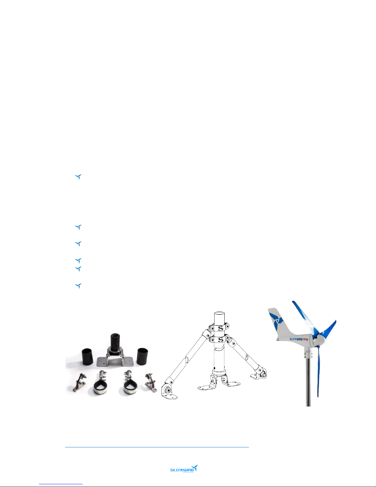
Vessel/motorhomes equipped with wind generators typically have a dedicated mast used as the mounting
post for the wind generator.
Vibrations generated by all wind generators will be transferred down into the vessels hull or the
motorhomes walls via the mast and the fittings. These are called “harmonics”.
Therefore, how the mast is fitted to the deck/motorhomes is one of the most important parts of the
installation.
In order to eliminate harmonics and get best performance out of the SILENTWIND Pro we recommend the
following when installing on a vessel/motorhome:
Do not position SILENTWIND Pro in line with a backstay or centered position on your stern. It
needs to be positioned above the Bimini, coach house or any other construction. To work most
efficiently and with the lowest noise emission all wind generators need “clean air”. During the
wind tunnel testing it was clearly proven that any turbulence will decrease the SILENTWIND Pro
performance. The anemometer on a vessel is usually on a different Hight of the wind generator,
the windspeed shown will not be the same as on the wind generator. Please take this is account.
Avoid attaching the mast on any existing structure; for instance, a frame which holds solar panels,
Biminis, rail fitting, etc.
Use rubber inserts between deck and mast base, rubber washer for screws or bolts to remove any
latent vibrations before entering the hull/motorhome.
Use the supplied rubber insert between the SILENTWIND Pro and the mast.
All brackets, like mast clamps, need rubber strip insertions (3-4mm thickness and of medium
density) between parts.
An upper mast bracket should be installed approximately 20 cm below the lowest part of the
blades tip to stabilize the mast.
Once the mast is mounted you can start the installation of the SILENTWIND Pro.
Video Link – Silentwind Scantrut Mas Assembly:
https://www.youtube.com/watch?time_continue=1&v=0dVJIwbwAWY
Page 35
35
Silentwind Pro – User Manual
March 2019
SILENTWIND Pro ASEMBLY
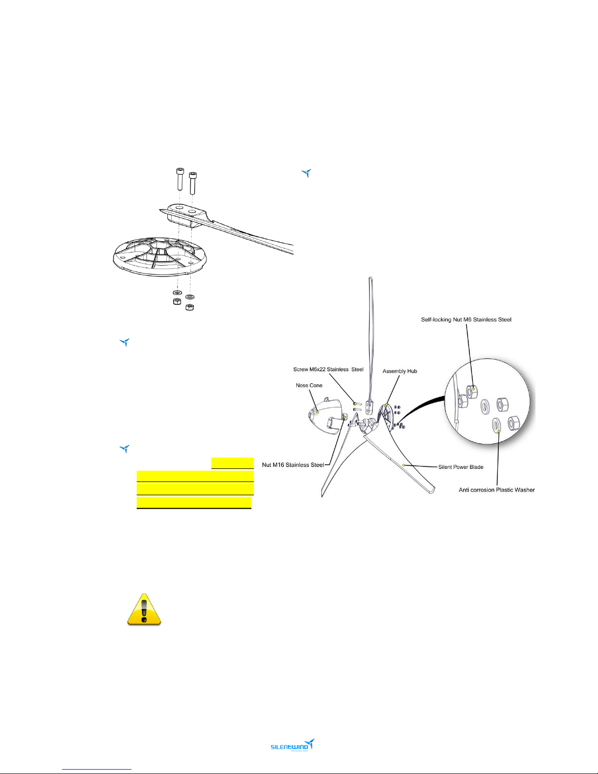
1ST - CONNECT THE 3 BLADES TO THE ASSEMBLY HUB WITH THE ENCLOSED SCREWS
The fastening torque is 7-8 Nm equivalent to a
weight of 7-8kg on a 10 cm long lever arm, upright to the
lever arm. If the fastening torque is too high, this will
destroy or damage the blades. If the fastening torque is
not high enough, the blades can get lose. A wrong
fastening torque is a considerable safety risk.
Move each rotor blade in
running direction towards
the edge of the blade guide
of the hub. The running
direction is clockwise
looking from the front.
Before the final tightening of
the blade screws, make sure
that the distance between
the blade tips is the same, in
order to avoid vibrations.
Take a measuring tape and measure the distance from all three tips of the blades and adjust
accordingly (Approximately 990mm ± 5mm tolerance). The blades have been balanced statically
and dynamically.
An incorrect tightening torque represents a significant security risk. Regularly control
the fixation of the blades!
The enclosed nylon discs protect against electrolytic corrosion.
Page 36
36
Silentwind Pro – User Manual
March 2019
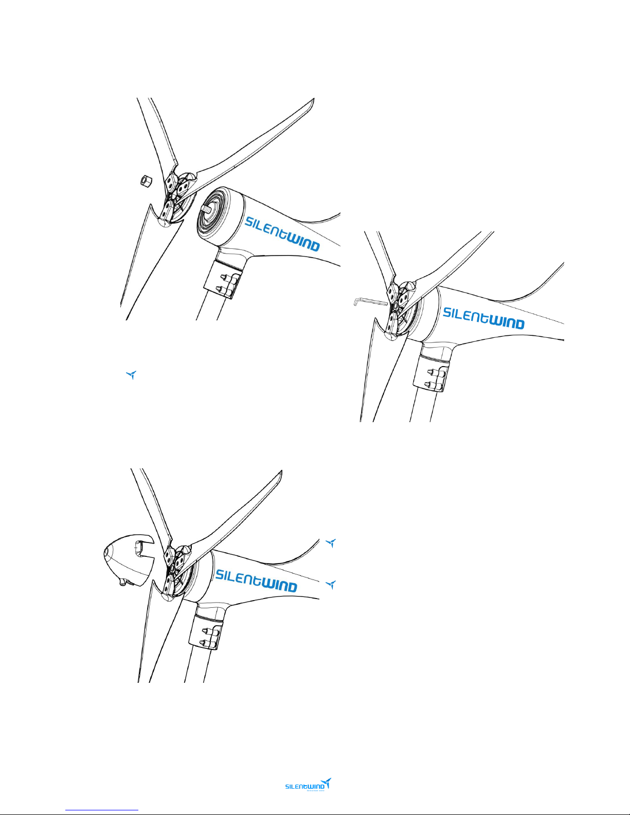
2nd FIX THE SET TO THE SILENTWIND Pro SHAFT WITH THE ENCLOSED SCREW NUT
(use the enclosed hexagon socket screw key).
The M16 Nut and the Hub is marked. The
arrow on the central nut should point towards
SILENTWIND Pro head. Do not over tighten
the central nut.
3rd SNAP THE NOSE CONE INTO PLACE ON THE ASSEMBLY
HUB
If possible, it is best to attach the hub with the blades
to the shaft at the very end of the mounting procedure.
After a week or so check the central nut which
connects rotor hub to shaft for tightness. Also check the 6
bolts which fix the blades to the hub.
Page 37
37
Silentwind Pro – User Manual
March 2019
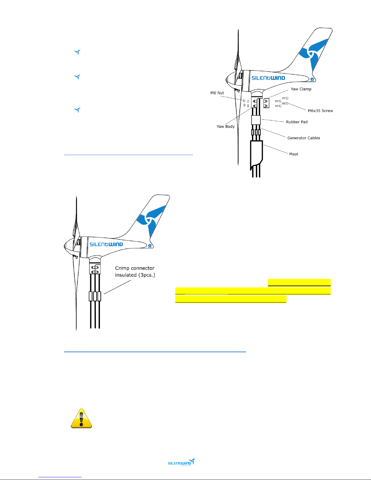
4th MOUNT THE SILENTWIND ON THE MAST
Fix the 4 hexagon screws to the yaw clamp after
inserting the rubber pad.
When tightening the screws take care for a
uniform, circumferential tightening of the 4
screws.
The tightening should be made with small
increments in order to avoid damaging the
marine grade painting.
Video Link - Silentwind Blade Assembly:
https://www.youtube.com/watch?v=0avf_y2U3gY
ELECTRICAL INSTALLATION
Make an extension of the 3 cables AC, using a crimp connector
insulated will be necessary since the SILENTWIND Pro will be
fixed in the mast and the Hybrid Boost Charge Controller will
not be fixed in the same place.
If there is enough wind speed when connecting SILENTWIND
Pro, this will immediately generate electric power at the end
of the 3 AC-wires without being connected to the Hybrid
Boost Charge Controller. Therefore, we recommend blocking
the SILENTWIND Pro blades with a rope before connecting the
wires to the Hybrid Boost Charge Controller.
Video Link - Silentwind Cable Connection:
https://www.youtube.com/watch?time_continue=1&v=1W4HlPHQ_C4
Connect insulating screw joints in the end of the wires coming from the battery. In case you do not use
the connecting wires, we recommend the use of crimp type cable sockets to connect your wires directly
to the Hybrid Boost Charge Controller.
Install a fuse between the Hybrid Boost Charge Controller and the battery positive pole, as
close as possible to the battery.
Page 38
38
Silentwind Pro – User Manual
March 2019
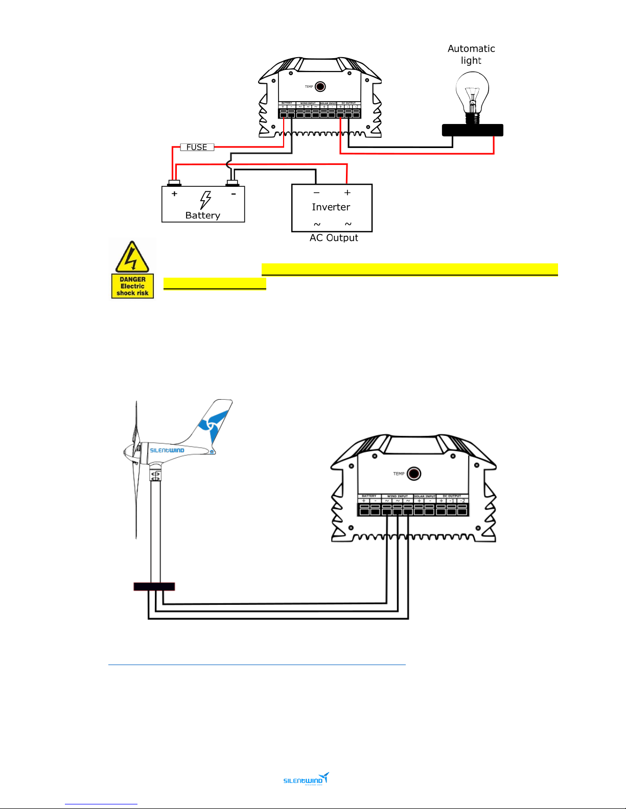
It’s very important that you first connect the Hybrid Boost Charge Controller to the battery
with the right polarity. The confusion of plus (red) and minus (black) will destroy your Hybrid
Boost Charge Controller.
After the connection of the battery you can connect to SILENTWIND Pro, the solar panel and if required a
load output with maximum 10A.
The 3 AC output wires must be connected to the 3-screw terminal on the back of the Hybrid Boost Charge
Controller. In a 3 phase AC system the connection order/polarity does not matter.
Video Link - Silentwind Charge Controller Installation:
https://www.youtube.com/watch?time_continue=5&v=DS5oi9-2Hbk
Page 39

39
Silentwind Pro – User Manual
March 2019
Page 40

40
Silentwind Pro – User Manual
March 2019
 Loading...