

SILENTRON 5500 Silenya HT GSM Top, 5501 Silenya HT GSM Free, Silenya HT Series, 5502 Silenya HT Top, 5503 Silenya HT Free Instruction Manual

1) FOREWORD
2) FEATURES
2
3
3
4
3) USER MANUAL
4
6
7
7
4) INSTALLER MANUAL
5) PC MANAGEMENT
6) SETTING ALARM DEVICES
7) APP
8) APPENDIX
SILENTRON FW
MANUAL
Instruction manual
CONTENTS OF THE FIRST SECTION – USER AND THE INSTALLER MANUAL
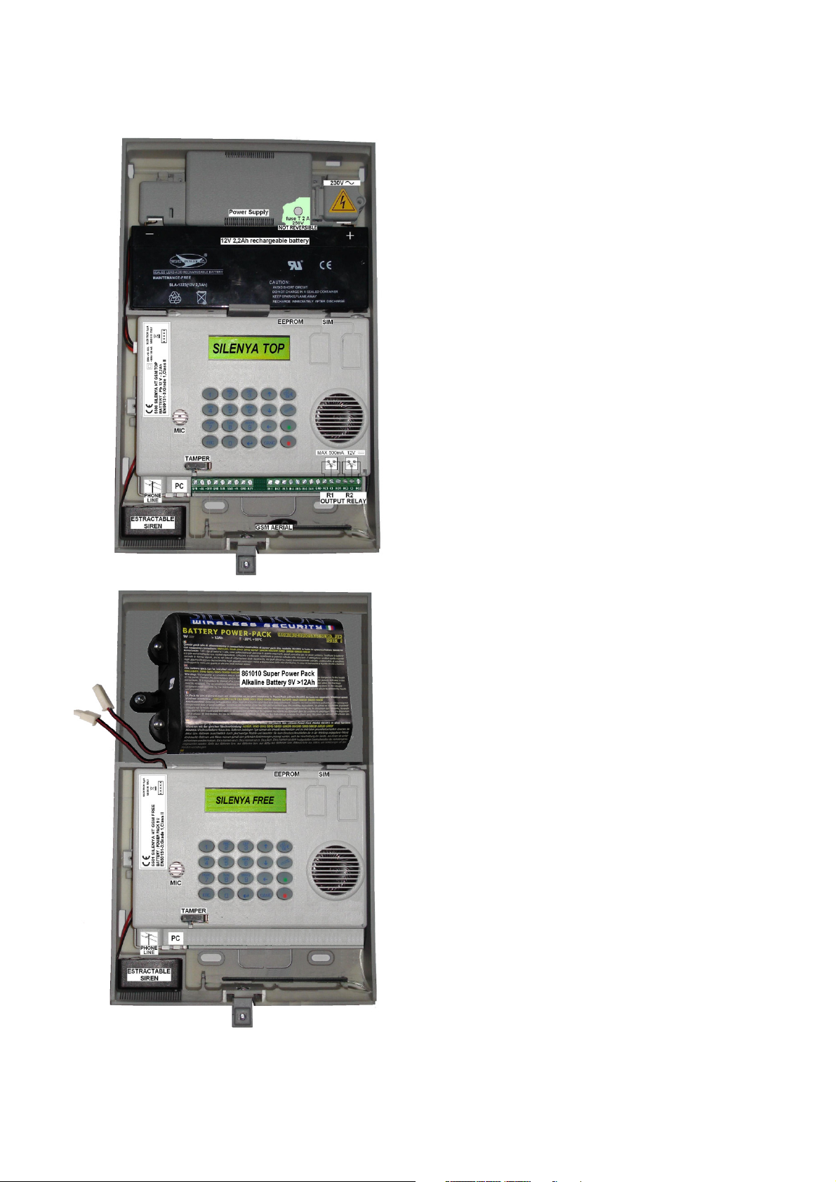
Free Models (5501-5503): Technical Specifications - Back-up Power – Electronic board 12
Built-in Telephone Transmitters: Specifications 13
Commissioning - initial setup 14
Diagram of menu when control panel is first commissioned - Programming procedure - Messages 15
Availables Firmwares of the control panel 2
Overview and differences between the two control panel models.
Diagram of EN compliant system (fully expanded configuration) - Hardwired external devices.
Table of EN 50131 products and accessories
System project - Audio Wizard - Least expanded configuration
User/Installer codes and access levels - Meaning of keys
User Access for setup functions. User is authorized to setup messages, tools, settings, remote
technical support, installer code, temporary exclusion (isolation) of a detector.
User Access for operation purposes. User is authorized to display the event history log, perform
testing and setup relay 1.
Event Alert - User operations (figure): arming/disarming from control panel.
Arming/disarming using remote controls and keyboards - Automatic arming.
Disarming under duress - Automatic relay 1 operation.
Alarm functions - Control panel’s telephone section - voice messages and SMS – Call. 7
Telephone calls to central monitoring station – Medical assistance calls - Calls to the control
panel
Remote Control functions - Editing address book numbers with SMS – SIM card balance –
Remote audio monitoring
Hands free telephone conversation - Other functions - Setup from PC
User Information
Precautions - Opening, positioning and fastening – Tamper Protections - Network connection 10
Testing radio reception - Top Models (5500-5502): Technical Specifications
Electronic board of Top models: connections 11
4
5
8
9
9
9
11
Editing voice messages - SMS -SMT - Event Messages 15
Setting Phone book - Tools: setting external devices (remote controls, alarm zone codes, AND
Setting hardwired zone - Functions Setting Menu 16
Function Setting (continued) - Digital Protocols 17
Additional data on digital protocols 18
GPRS transmission (data) - remote technical support (remote maintenance) 19
function, 24H areas.
Operations to perform settings over the PC 19
Receivers, sirens, keypads 20
Utilities for Smartphone users 21
EC compliance to applied regulations 21
Variations supplied by Silentron’s firmware 22
16
1
1 FOREWORD - Availables Firmwares
1.1 Declaration of conformity
The manufacturer declares at chapter 8 that the panels here described
are conforming to the UE regulations when them are used with the
firmware EN 50131.
1.2 SILENTRON firmware
In compliance with general regulation criteria, this firmware allows to
perform better solutions for end-users. These operations are therefore
not strictly compliant. Main not compliant operations are: 1) external
detectors’ differentiated alarm management, which the standard does
not mention 2) immediate alarm transmission dynamics, the standard
requires that it be delayed, 3) immediate display of alarm location during
partial arming. for a better information to end-user. The other operating
differences are specified in the paragraphs pertaining to each topic. IMQ
certification will be void when the other optional firmware is selected.
Installer and user are responsible for firmware selection. The
manufacturer is available to maintain that some of the operational
decisions envisaged by its firmware improve user’s safety and usability.
1.3 Silentron firmware selection
The control panels are developed with the EN 50131 firmware and you
must enter the appropriate menu (see 4.8.5.20) to change firmware
version. Please refer to the specific instruction manual should you wish
to replace the firmware. All of the programmed settings will be
maintained when firmware is replaced.
2 OVERVIEW
Silenya HT control panels are devices that allow to manage and control
alarm and home automation systems. All external devices and functions
are setup according to each location’s requirements.
Various accessory devices may be hardwired to the control panels and
control panels may be fitted with home automation actuator boards.
These devices are used to handle the control panel, detect various
kinds of events and generate various types of warning and/or deterring
alarms.
2.1 DIFFERENCES BETWEEN THE CONTROL PANEL MODELS
Silenya are extremely powerful control panels that may be used to
develop small and large systems using from 1 to over 90 detectors. You
can select between four available control panel models according to the
type and size of the system to be installed. The models feature different
power supply modes and some models are supplied with a built-in
GSM-GPRS module while some types do not. It is not possible to add
elements to a model that is not supplied with them since the different
features are native ones. All control panels are equipped with a built-in
PSTN telephone transmitter (landline line).
5500 Silenya HT GSM Top: primarily powered by 230V mains, with
built-in GSM/GPRS module
5501 Silenya HT Top: primarily powered by 230V mains, without GSM/
GPRS module
5502 Silenya HT GSM Free: primarily powered by alkaline batteries,
without 230V, with built-in GSM/GPRS module
5503 Silenya HT Free: primarily powered by alkaline batteries, without
230V, without GSM/GPRS module
2.1.1 IMPORTANT NOTE: This manual sets out the features of the
most complete model, 5500 Silenya HT GSM Top. Please note that all
of the functions that require a GSM/GPRS telephone module will not be
available for the models supplied without this device. Likewise all of the
functions linked with a mains power supply will not be available for the
"Free" battery powered models. This manual therefore applies to all
models and highlights only the shortcomings which do not directly result
from the different mentioned above features. Examples:
a) Models without GSM/GPRS module do not require a SIM card, do not
send SMS and therefore do not require SMS settings to be performed.
These models can receive outside calls only from a PSTN landline. b)
Battery-powered models which are not powered by the main power
supply do not feature hardwired inputs/outputs. The GSM/GPRS module
of these control panels cannot be constantly on and is activated only
through the control panel’s control and/or in the event of an alarm.
2
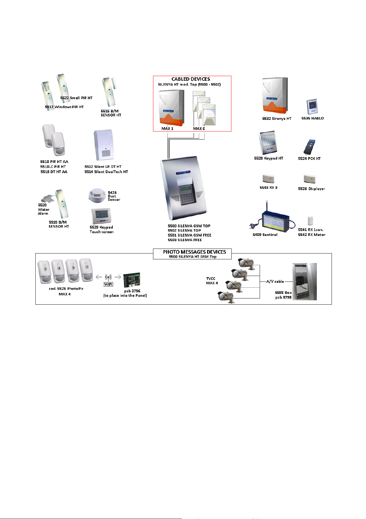
2.2 EXAMPLE OF A FULLY EXPANDED CERTIFIED SYSTEM
Caution! Up to 99 supervised external devices (detectors, keyboards, sirens, etc.) may be connected to the system. There is no limit as far
as the number of unsupervised (not certified) external devices is concerned.
2.3 CONVENTIONAL HARDWIRED EXTERNAL DEVICES (Top models only)
Control panels are fitted with hardwired lines to which you can connect:
• up to 6 detectors powered over a 3 wire balanced line
• no. 1 (or more) self-powered siren with built-in battery
• no. 1 (or more) not self-powered built-in siren
• no. 1 electromagnetic key (TAG) supplied with at least 300 million code combinations to arm/disarm control pane over a balanced line.
• no. 1 control board with metal box part 5598 (installation under the panel) for 1-4 hardwired CCTV cameras
• no. 1 WiFi control board part no. 3796 (installation into the panel) for operate 1-4 wireless PhotoPir (detector with camera onboard)
2.4 EN 50131 WIRELESS SILENTRON PRODUCTS
CODE DESCRIPTION Grade Class
5510 PIR HT AA* - Passive Infrared Detector - LB 32442 PCB 89423/C-1,C-2 1 II
5510LC PIR HT - Passive Infrared Detector - LB 32424 PCB 89424/A1-A2 1 II
5512 Silent LR DT HT - Passive Infrared Detector - LB 32440+32411 PCB 89421/A 1 III
5514 Silent DualTech HT - Dual Technology Detector. PIR + MW - LB 32430+32401 PCB 89420/B 1 III
5515 B/M Sensor HT ** - Magnetic Contact - LB 300301 PCB 89235/C 1 II
5517 B/M Window PIR - Passive Infrared Detector - LB 300091 PCB 89316/C 1 II
5518 DT HT AA * - Detector DualTech. PIR + MW - LB 32423+32412 PCB 89423/C1-C2 1 II
5521 B/M PIR HT - Passive Infrared Detector - LB 300095 PCB 89317/C 1 II
5522 B/M Small PIR HT - Passive Infrared Detector - LB 300099 PCB 89319 1 II
5524 PCK HT – 2 way remote control - up to 32 - LB 300495 PCB 89237/B 1 II
5528 KeyPad HT bi-directional keypad - up to 32 - LB 300431 PCB 89238/B 1 II
5532 SIRENYA HT bidirectional outdoor siren - LB 30446 PCB 89277/B 1 III
3
2.5 INSTALLER’S RESPONSIBILITY & PERFORMANCE
Each alarm system consists of several external devices (detectors, sirens, control points, keyboards, etc.) which are controlled by one of the
control panels that are featured in this manual. This manual describes all of the panels’ features, their use and their operation. A professional
installer has the essential task of identifying which functions are required by the customer, to foresee the safety measures required by the
system and to install the system with diligence and professionalism. The installer must integrate the instructions supplied in this manual with
the operating variables being implemented in the system in order to allow the user to fully master all of these functions
2.5.1 INSTALLER AND USER AUDIO WIZARD
In order to facilitate the system’s implementation and use, these control panels feature an audio wizard that illustrates the available
operations during their use. For this reason some marginal and/or highly intuitive aspects of the control panels may not be mentioned in this
manual. These control panels have been designed in such a way that no user operation could damage the system.
2.5.2 MINIMUM SYSTEM REQUIREMENTS FOR EN 50131-1 AND FOLLOWING STANDARD COMPLIANCE
The system must foresee at least one battery or battery pack powered control panel, an enabled built-in telephone dialer, a detector and an
external siren (grade 1 certified). Up to 99 devices (detectors, sirens and keypads) may be managed with a fully expanded system. The
detectors are be divided into three groups (zones) and each zone can be individually armed.
Up to 6 hardwired detectors may be connected to Top model control panels using a balanced line. You can freely select for which of the
three zones you wish to setup the detectors.
3 USER MANUAL
The following figures describe all of the operations that the user can perform using the control panel keypad and/or the remote control. The
figures specifically describe how to partially and fully arm the system, how to test it and the user settings.
Caution! Each item that is entered using the keypad must be confirmed using the () key.
3.1 ACCESS CODES - Caution! Keypad locks for 3 minutes when the wrong code is entered more than 5 times!
You must use two 4 and 8 digits access codes, the USER code and INSTALLER code, in order to operate the control panel. These different
codes are setup by the installer during the installation. After the installation, the user must change the temporary user code programmed by
the installer to have full system’s ownership. The installer will therefore need the user’s authorization (the new code) in order to perform any
changes to the system after this time.
Enter the USER code– Confirm it ( ) – scroll down to INSTALLER CODE – enter INSTALLER code.
3.2 ACCESS LEVELS
Level 1: Control panel can be accessed by anyone: anyone can see the display’s basic screen
Level 2: User access: user accesses control panel by entering a 4digit code
Level 3: Maintenance access: control panel's settings can be accessed only by entering the installer code
Level 4: Manufacturer access: control panel’s upgrading operations may be performed only when the control panel is disabled.
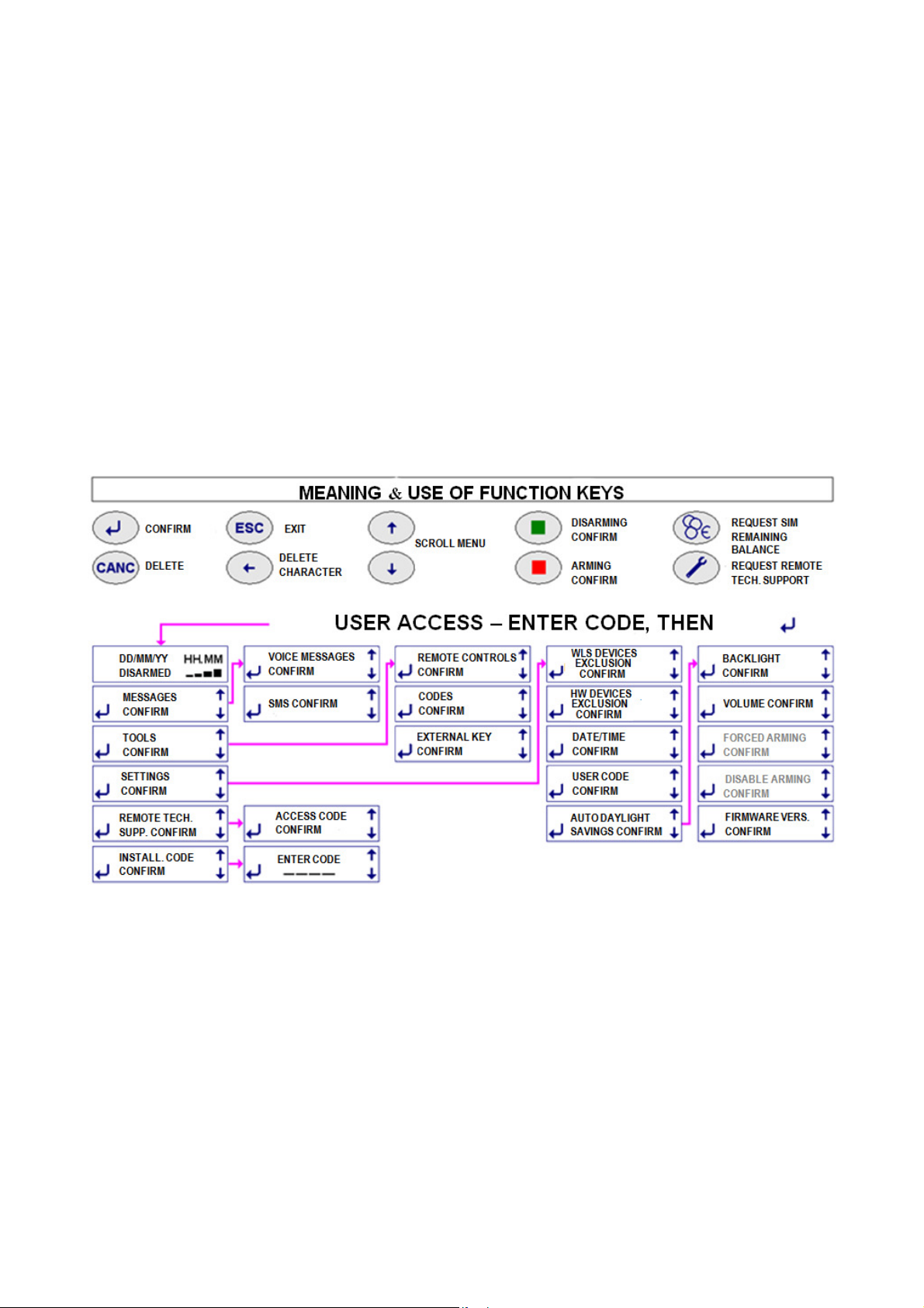
3.3 MEANING OF FUNCTION KEYS - see drawing.
3.4 USER ACCESS FOR SETUP PURPOSES ( see previous table)
Once the user code is entered, followed by , the available menus to setup and operate the control panel are displayed. Operations are
intuitive and described in the following sections.
4

3.4.1 MESSAGES: used to record/delete the voice messages and SMS (see 4.8.2 ) that are sent over the telephone to the numbers setup
in the phone book during the relevant event.
3.4.2 TOOLS : used to setup new remote controls, to delete any ones that may have been lost and to edit previously setup remote controls
(see 4.8.4.1). It is also used to create, delete and edit arming and disarming codes with different restrictions (see 4.8.4.2) as well as to setup
an additional TAG with the same options same has been installed.
3.4.3 SETTINGS: used to access sub-menus for the following options (see 4.8.5) :
• Isolate (exclude) one or more hardwired or wireless detectors. The events signaled by the excluded detectors will be stored in the
system without triggering any other function.
• Update date and time
• Change USER code, to be performed after installation to detain be exclusive access.
• Enable or not enable automatic daylight saving time.
• Enable display’s backlight permanently.
• Forced arming: only the installer can access the function that allows to program system arming at specific set times.
• Disable arming: this function is not available.
• Display your system’s firmware version. It may be updated or implemented as required.
3.4.4 REMOTE TECHNICAL SUPPORT: to create a code that is required to request remote assistance. This code can be used to connect
the control panel to the installer’s servicing center by dialing it over the telephone when the control panel answers the call. This operation
automatically disables the control panel as the service is enabled. The control panel will be automatically enabled when the connection to the
servicing center ends. Caution! This code must be different from the user code: see 4.10.
3.4.5 INSTALLER CODE: by accessing this menu, user will grant installer's access as this is where the installer will enter his own access
code. This procedure will ensure that the installer is not able to access the unit without user’s authorization.
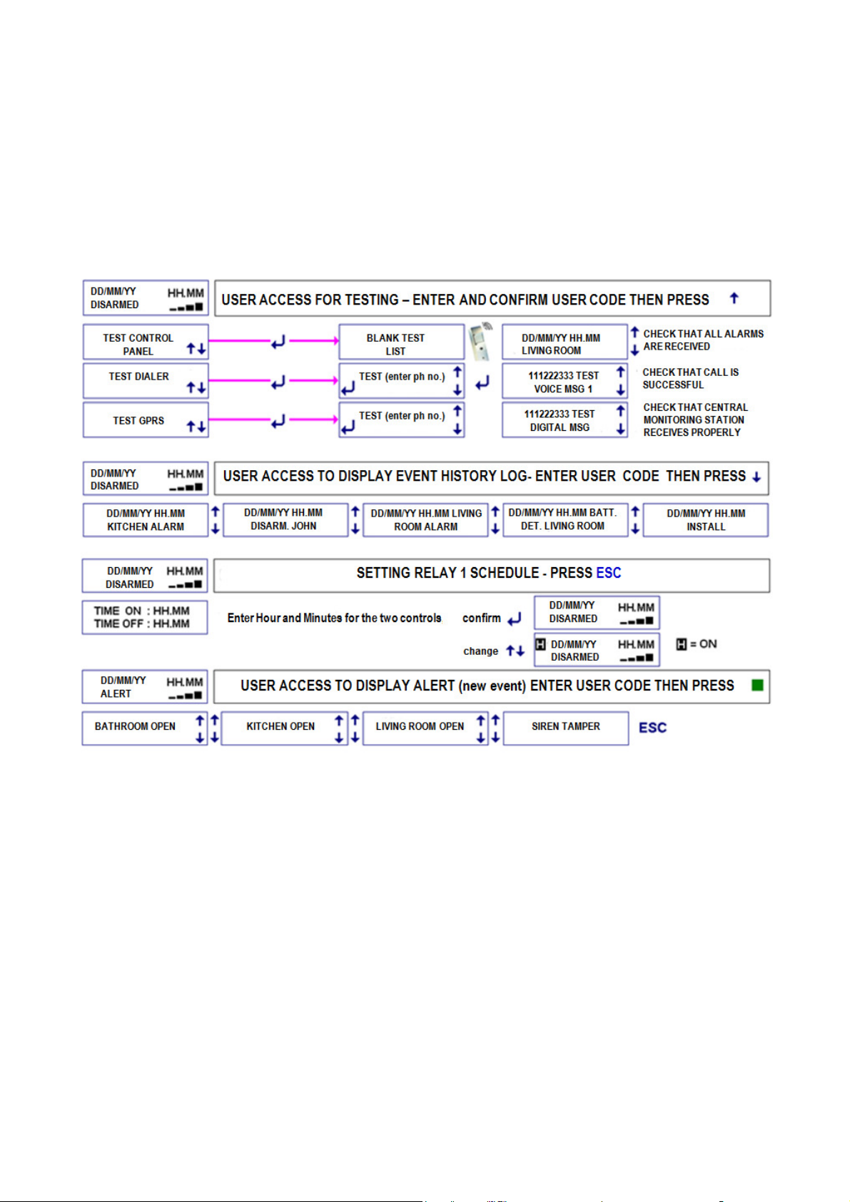
3.5 USER ACCESS TO USE THE SYSTEM (see following table)
As illustrated, control panel’s operations can be accesses with different modes.
3.5.1 TESTING CONTROL PANEL - USER/INSTALLER ACCESS - SYSTEM ADJUSTMENTS
3 types of tests are available: CONTROL PANEL ( DETECTORS) – DIALER - GPRS (digital messages sent to the central monitoring
station) . When TEST mode is enabled using USER code, no alarm will be triggered, but tamper protection will continue to be enabled.
Caution! You must enable TEST mode using the INSTALLER code in order to change any batteries and/or service the system since this
code will also disable tamper alarm. This also allows you to access radio signal test mode (see FIELD METER 4.2).
Procedure: test the remote controls and trigger all detector’s alarm by opening protected doors/windows, moving inside areas that are
protected by volumetric detectors, breaking infrared barriers, etc. Always wait at least 5 seconds between alarms, up to 99 subsequent
alarms will be stored in the system. Perform the test in two phases in the event of multiple detectors. Once testing has been completed,
check that each alarm has properly transmitted as well as its reception range over the two operating CH1 and CH2:
H = excellent, M = good , L = low. All range levels are to be viewed as effective for signal reception purposes since the test is carried out
with the receivers’ attenuation required by the standard. Perform a “real” test by arming the control panel and triggering an alarm should
there be no display for either frequencies as the signal is attenuated during TEST mode in compliance with Standard 50131 and the unit
could be properly operating. Contact support service in the event that no alarm is triggered.
TESTING WIRELESS SIRENS: in TEST status, sirens have been properly connected if a beep is heard when pressing the red button.
3.5.2 TESTING DIALLER and GPRS : enter the required number to be dialed and verify the outcome.
3.5.3 DISPLAYING EVENT HISTORY LOG: the control panel stores any operation and or event of taking place. Event display all events and
operations by accessing the event history log. Some events are displayed abbreviated as follows:
Telephone calls : ← = call from the control panel; → = call to the control panel date and time of call; V = voice message; S = text message;
D = digital protocol; CONTACT ID protocol type = type of digital protocol; INSTALL = installer; TELESERVICE = remote management;
SERV.CLIENTI = other support service; OK = successful call, KO = failed call; OC = busy number; NO= no answer
User/installer accesses/operations: Time and date of event; INSTALL = installer access; USER = user access; PROG = setup;
CHANGED NUM . = change in the number; CHECK GSM = automatic switching on and off of the module; REMOTE = remote assistance ;
DEL = delete
Operations and alarms : ARM = total arming ; ARM AB = arming A+B zones; DISARM . = not armed; EXT ALM. = External alarm (not
managed to in this version); OPEN = open window/door; TAMP = tampering; ALM = alarm ( name of detector is displayed) ; SCAN = radio
interference, DEL= delete; BATT = low battery; SERV = operational; FSERV = out of service; SUPERVIS = supervision failure; REM =
remote control; DET = detector; COD = code ( keypad); HW = hardwired input; PH FAILURE = telephone line out of service, NO GSM = No
GSM range; 230V = 230V power failure;
3.5.4 SETTING RELAY SCHEDULE: Top control panels are equipped with a relay that can switch on electrical loads for home automation.
You can set the time in which operations should start and end using this function.
3.5.5 DISPLAYING NEW EVENTS: enter the USER code and press the green button to display new events when the word ALERT is
displayed on screen. The ALERT message will clear when the condition triggering the event is removed, but it will continue to display until it
is removed.
5
3.6 ACCESSING CONTROL PANEL TO ARM/DISARM THE SYSTEM
The control panel features 3 intruder alarm zones which can be individually armed according to the system’s configuration and user’s
requirements. The unit also features three additional zones for the following type of alarms: 24H PANIC alarm - 24H ROBBERY alarm - 24H
TECHNOLOGIC alarm. These zone are always armed in order to detect such occasional alarms. Technologic alarms involve monitoring
smoke, water and gas detectors as well as other sources of danger. Caution! The 24H Panic and 24H Technologic alarm functions are not
certified.
The system can be armed and disarmed directly from the control panel or using the wireless keypad or the remote control. You must set
appropriate arming delays and alarm delays for the detectors located in the entry/exit route in order to arm and disarm the system directly
from the control panel without triggering false alarms.
3.6.1 ARMING/ DISARMING FROM THE CONTROL PANEL
• ARMING: Enter USER code or another approved code to display the three alarm zones: A, B and C. Press the red button to arm all
three zones. Press 1 ( A) , 2 ( B) or 3 ( C ) to exclude a zone (one or two zones), then press the red button to partially arm the system.
Excluded zones will disappear from the display. All operations will be displayed and confirmed with a voice message. All armed zone
will display flashing during the setup delay time.
• DISARM: enter a code as above and then press the green button. This operation will be displayed and confirmed with a voice
message.
• Arming with new events: if the word ALERT is displayed, you will be able to arm the system after having entered the user code and
having viewed the event that will automatically display. If the cause that triggered the event is not removed, the control panel will ask
you to force system’s arming. Press the red button and use the above described procedure to force system's arming.
• Disarming with new events: if the word ALERT is displayed, you must display the new event by entering the USER code and pressing
the green button once system is disarmed.
Caution! Arming is denied and the condition is displayed if one or more detectors are alarmed during arming delay. We recommend that you
do not leave and make sure that the system has been successfully armed if arming delay has not be set for some of the detectors located
along the exit/entry route.
Caution! If any detector has been set with an alarm delay, adjustable from 1 to 45 sec., same will trigger an alarm once delay has elapsed
unless the control panel is disarmed in the meantime. An immediate alarm will take place when a detector with an alarm delay detects a
movement and a second detector without an alarm delay is also triggered. In this case, telephone transmissions will begin after 30 seconds
or, when set for a longer time, after entry/exit delay time.
Caution! After 5 wrong inserting codes the panel keyboard will be blocked during 3 minutes.
6

3.6.2 ARMING/DISARMING FROM THE REMOTE CONTROL (5524) AND/OR ADDITIONAL KEYPADS (5528)
TOTAL ARMING: voice confirmation or 3 beeps
Additional Keypads: enter the code and then press the red button
Remote Controls: press the red button.
PARTIAL ARMING: voice confirmation or a long beep
Additional Keypads: enter the code , exclude zones by pressing A, B, C to leave only the ones to be armed, then press the red button.
Remote Controls: press the white button to arm A and B zones (see remote control’s manual for additional options).
DISARMING: voice confirmation or a beep
Additional Keypads: type the code then press the green button
Remote Control: press the green button
Caution! Unless remote controls and keyboards are setup differently, disarming involves all zones. You must arm individual zones after
disarming the system in order to partially arm it.
Caution! Models with GSM module (5500-5501): You may experience some issues in disarming the system after an alarm when using
additional remote controls/keypads during GSM phone transmission. In this even, disarm the system from the control panel’s keypad.
WARNING: alerts can be managed only using the control panel. You cannot therefore use remote controls or keypad in the event of alerts.
Caution! The control unit manages keypads and remote controls low battery status. These devices can no longer be employed without
replacing their batteries after 25 reports or 30 days from the first report.
Caution! AUTOMATIC ARMING: when this function is setup by the installer, the system will enable automatic arming, forcing the system in
the event of alerts, one minute after having emitted a long beep.
3.6.3 DISARMING UNDER THREAT - DURESS ALARM Caution! the same operation takes place when the system is disarmed by
entering a DURESS code (a code specially setup by the installer), but in this case, the telephone transmitter will be enabled and preset users
will be called. The control panel will display an ALERT in compliance with the standard.
3.6.4 AUTOMATIC RELAY 1 OPERATION: Press ESC to access clock setup for this option, when used.
3.7 ALARM FUNCTIONS
When an alarm is triggered, the control panels enables the built-in siren (which can be removed), local alarm devices (sirens and
other deterrents) and landline and/or mobile telephone calls as follows:
3.7.1 Audible messages and alarms (please also see "Telephone Section")
• Audio wizard: Silenya HT are talking control panels which provide pre-recorded not encrypted data messages.
• Pre- alarm: pre-alarm voice message broadcasted during the delay, when detectors delayed have been setup.
• General Alarm: built-in and all external sirens sound for three minutes.
• Panic alarm when the system is partially armed or disarmed (this function is not certified): Sirenya and SR –P sirens start
sounding .
• Robbery alarm: only preset calls are made with a silent alarm. This function can be used also to call
• medical or other emergency telephone calls (you must record the message appropriately).
• Technologic alarm: a 15 seconds intermittent sound is transmitted by the control panel (this function is not certified).
• Tamper alarm when system is disarmed: the message ALERT is displayed and remote calls are enabled without any sounds being
triggered.
• Tamper alarm when system is partially/fully armed: the control panel enables a general alarm.
Caution! Please note the following :
a) sirens will be silenced during any type of alarm by disarming the system.
b) Up to three alarms are accepted for each detector during each period in which A, B and C zones are armed. This feature prevents a faulty
detector from becoming a public nuisance. The count restarts every time each zone is armed. The " detectors isolation" function ( 3.4.3 ) is
used to temporarily exclude a detector in the event of a fault.
3.7.2 TWO-WAY TELEPHONE SECTION - TELEPHONE CALLS
During the installation, appropriate messages are recorded/written and assigned to the telephone numbers to be dialed in the event of an
alarm. The numbers of the user’s family members, friends and law enforcement will for example be assigned to alarms. Assigning the
installer’s number for alarm calls is not useful, but it is useful to assign his number for "low battery" calls. Phone calls to the police require
prior approval from the user according to each country's regulation. Based on the control panel’s features, messages are transmitted over:
PSTN landline: all control panel transmit 6 voicemails and 6 voice messages assigned to 6 specific events which are transmitted over the
landline to up to appropriately setup 63 user phone numbers.
GSM Mobile Network: control panels model 5500-5501 are equipped with a GSM module and send the above messages over the GSM
network , with a SMS message priority. 11 default text messages with a technical content are transmitted as a result of event. Each of the
available 63 telephone numbers may be assigned to receive one or more voice messages and/or text messages. The hour and date of the
event occurred will be showed in SMS.
Caution! When a detectors is programmed with a delay, the phone calls and text messages will be transmitted 30 seconds after the event.
3.7.2.1 RECORDED/WRITTEN VOICE MESSAGES AND SMS: the default settings foresee 6 main events which can be changed/edited.
(see 4.8.2) . Your installer will setup messages that are appropriate to the events.
Caution! Those who will be called by the control panel for a new event will listen (repeated twice) or read the uncripted message, identifying
its origin from the phone number and/or the message itself.
3.7.2.2 Default SMS (MODELS 5500-5501) - Note: messages 6,7 and 11 are only for model 5500).
The control panels also feature 11 technical related SMS, which will be sent to the appropriate numbers. See 4.8.2.4
7

Detector ID: properly “labeling" each detector and performing appropriate voice recordings during setup, will allow the user to receive
messages supplying their exact source.
3.7.2.3 TELEPHONE CALLS TO CENTRAL MONITORING STATIONS: the control panels use digital protocols that are suitable for
monitoring stations transmissions. These protocols must be properly setup according to the instructions provided by the receiving central
monitoring stations. These messages can also be transmitted over the mobile network when the control panel is fitted with a GSM module.
3.7.2.4 CALLS FOR TECHNICAL SUPPORT: user can enable the control panel to automatically contact with the stone or (should he
provides the service) to allow system’s remote servicing and tuning.
3.8 USER’S REMOTE OPERATIONS - HOME AUTOMATION FUNCTIONS (THIS FEATURE IS NOT CERTIFIED).
All control panels can be called over the landline by dialing their number. Only until final model 5500 can be called over the GSM line by
dialing the number of the employed card. Control panel model 5501 also features a GSM module, but it cannot receive calls as it is normally
turned off for power savings purposes.
3.8.1 “Guide” message no. 7: this is the message that will automatically play when calling the control panel. This message recording must
contain instructions for the user regarding which numbers and symbols must be pushed on the phone to execute the preset commands.
Recording must be performed during system’s installation. Many of the functions supplied by the control panel’ cannot be fully described as
they vary based on an witch solutions have been adopted for the system.
3.8.2 CALLING THE CONTROL PAN OVER THE PSTN LINE
Caution! The control panel will answer incoming calls over the PSTN line only after the “Guide” message no. 7 is recorded and after the
remote technical support access code is setup. Without the above programming the control panel will not answer calls. To call, dial the
number of the control panel and hang up after two rings. Call again as soon as you have hung. the the control panel will reply by playing the
guide message or by beeping when no message has been recorded. . Wait for the message to finish playing and dial the user code followed
by # . Continue by performing the required functions.
3.8.3 CALLING THE BUILT-IN GSM MODULE (only with 5500 model)
The GSM module replies immediately to incoming calls. Dial the user code followed by # . Continue by performing the required functions.
You do not need to dial the user code if the incoming number is authorized to directly access the control panel. ( ved.4.8.3 ) .
SMS Query: see paragraph4.8.3
3.8.4 OPERATIONS THAT CAN BE PERFORMED WHEN CALLING THE CONTROL PANEL.
• Arming/disarming. Dial 0# for system’s status. The control panel with reply with an unencrypted voice recording. Dial 0∗1# to totally
arm the control panel. Dial 0 ∗2# to arm only A+B zones. Dial 0∗0# to disarm it. The control panel will reply with a voice recording. Model
5500-5501 panels will also send a text confirmation via SMS at the end of the call.
• Controlling built-in relays: dial 20 ∗ 1# to enable relay R1. Some configurations see this relay being used to replace the command set
with the clock (see 3.5.4) . Dial 20 ∗ 0 # to disable relay. Dial 21 ∗ 1 # to enable relay R2 and 21 ∗ # 0 to disable it. This relay can be
connected to another electrical load for home automation. Please bear in mind during installation that relays can be
enabled/disabled/controlled only with specific system configurations.
• Controlling built-in relays: dial 20 # to check R1’s status. The control panel sounds 3 separate beeps when the relay is enabled and 1
single beep when the relay is disabled. Dial 21 to check R2’s status as above.
• Local controls: by dialing a number from 1 to 16, followed by ∗ 1# you will enable locally installed 1-16 receivers (for example, dial 12∗
1# to enable receiver 12) . By dialing a number from 1 to 16 , followed by ∗ 0 # you will disable locally installed 1-16 receivers (for
example, dial 12 ∗ 0 # to disable receiver 12).
3.8.5 USER BEING CALLED BY THE CONTROL PANEL
The control panel will call the user in the event of an alarm. When called, the user will be able to interact with the unit to disarm the system
by dialing the above described commands. This action is to be avoided in the event of an genuine intrusion.
When called, the user can also disable control panel’s preset dialing cycle by dialing # on the phone dial after having listening to the control
panels message and to the end of message beep.
3.8.6 EDITING STORED PHONE NUMBERS REMOTELY (ONLY WITH 5500 MODELS).
You can edit and the phone numbers stored in the control panel’s phone book via SMS using a telephone number authorized to directly
access the control panel. Write this SMS message by entering the letter A followed by the phone number without any spaces. For example:
A333555666 ( old number to be replaced) A333666888 (new number to be entered).
The unit stores the change and sends the following confirmation SMS: CHANGE MADE *333666888 *
3.8.7 SIM CARD BALANCE
press € key to enable hear SIM’s remaining balance (when number has been setup - see 4.8.3). You can also request remaining balance
from TIM, WIND or VODAFONE providers by sending an SMS containing only a question mark (?) to the control panel. When calling the
control panel from a mobile phone authorized for direct access, it will reply by sending you an SMS text with the remaining balance, control
panel's current status and last occurred events. The text will display the data separated by asterisks. For safety it is always better to use an
automatically chargeable SIM card.
3.8.8 REMOTE AUDIO MONITORING
You can listen to the environmental noise taking place near the control panel when the control panel calls a preset number or you call the
control panel using a PSTN landline. Press the ∗ key on the phone to listen to environmental noise remotely. Press the ∗ key again to stop
monitoring environmental noise and to dial different commands. Audio connection will end automatically within 60 seconds of inactivity.
8
 Loading...