

SILENTRON 4001 Centrale Sil-Bus 4A, 4003 Centrale sil-Bus 1, 5A Instruction Manual

1
REGULATION COMPLIANT CONTROL PANELS
EN 50131-1 ; 50131 A1/IS1; 50131-3; 50131-6; 50136-1; 50136-2
GRADE II - CLASS II - ATS: SP2/DP2 (with GSM inside)
Instruction manual 2001-3EN-GD160802GM
Control panel firmware version from 3790J02A and following versions (touch screen keypad from 3720J01A and following versions).
All products versions can be upgraded using the PC and special software
CONTENTS OF THE FIRST SECTION – USER AND INSTALLER MANUAL
1) FOREWORD Current regulations and their application – Certified System – Silentron FW 2
2) FEATURES Overview and differences between the two control panel models 2
Figure of the two control panel models – Diagram of IMQ compliant system 3
Table of IMQ certified products and accessories 4
Hardwired devices – Installer responsibility and performance– System designing – Audio Wizard 4
Minimum system requirements 4
3) USER MANUAL Table - User access during standard conditions 5
User codes and user access levels – Meaning of icons – Master and Slave codes 6
Changing codes - arming – test - Time/data and display settings 6
Temporary detector exclusion - Display event history 6
Access and event history log display – Entry/Exit delay - Disarming - Tag readers and applications 7
Disarming under duress – Direct and home automation controls 8
User access with events table 8
Remote control panel management over the telephone 8
Remote audio monitoring – Editing phone book – Alarm modes: intrusion and other modes 9
System protection 10
4) ALARM CALLS Outside calls 10
5) SPECIAL FUNCTIONS (not compliant) Home automation controls - Audio alerts - Access control - TTL connections TTL 10
6) USER INFORMATION Alarm systems overview 10
7) INSTALLATION MANUAL Upgrading control panels – Firmware version – Opening and mounting 11
Sistem's protection features – 230V connections and batteries 11
Electronics logic board (HW) 11
Power supply and batteries - current availability - Electric connections table 12
Hardwired balanced lines (not bus) – Bus cable sizing and safety 13
End of line resistors – Bus repeater 13
8) Touch-screen keypad Setting and addressing Bus elements 13
Built-in telephone transmitter - Features – Settings 14
Initialing operation – Addressing Bus elements 15
Table of installer access during operations 15
9) TOOLS menu Setting user code – Tag – Bus modules – Bus modules parameters 16
Modules' settings table 17
Detectors "AND" function 18
Setting multi-purpose Bus modules – Slave Touch-screen – Bus relay boards 18
Bus TAG readers 19
Adjusting Bus detectors – Managing hardwired inputs – Replacing Bus modules 19
10) SETTINGS menu System's parameters – Time functions 20
Scheduling weekly arming/disarming 21
Scheduling weekly home automation functions 21
SIM card management–Built-in relay–Excluding detectors–GSM/PSTN priority–Utility functions 21
11) MESSAGES menu Audio messages 21
SMS/SMT (technical) text messages 21
12) PHONE BOOK menu Setting phone numbers 22
13) DIGITAL MESSAGES Setting calls to the central monitoring station 22
Dual phone lines: setting calls to the centra l monitoring station 22
14) SETUP OVER THE PC Local and remote management 23
Connecting, configuring and managing the system from a local PC 23
Reading and writing data – Parameters of peripheral devices – Control panel's technical sheet 24
15) REMOTE MANAGEMENT Connecting, configuring and managing from a local PC-Remote management over GMTS 25
16) MULTI USER SYSTEMS Available configurations 25
17) MAINTENANCE Control panel maintenance instructions 26
18) APPENDIX EC conformity declaration – Applied regulations
SILENTRON FIRMWARE Variations supplied by Silentron Firmware 27-31
DIGITAL PROTOCOLS CODES TABLE 32
2
1 FOREWORD - CURRENT REGULATIONS AND THEIR APPLICATION (legal notes supplied by the manufacturer)
1.1 Laws and Regulations
These control panels must be installed in compliance with the local Laws.
1.2 IMQ Italian Certification - SECURITY SYSTEMS - EN 50131 . . . .
Compliance is achieved when all components have been certified. The system’s grade corresponds to the system component/components with lower grade.
1.3 INCERT certification of these control panels
This certification prevides the EN 50131 conformity and some caracteristics for Belgium only. To activate this FW it needs to entry in the right menu (see diagrams par. 8.4 and 10.6) to
confirm the choice. The control panel will function as here is described.
If used with the firmware automatically offered and within the limits and/or the instructions outlined for each application, these control panels fully comply with standards EN 50131-1;
50131 A1/IS1; 50131-3:2009; 50131-6:2008; 50136-2-1. Any adjustments and/or configurations must be performed within the specified limits.
1.4 SILENTRON firmware
In compliance with general regulation criteria, this firmware allows to perform operations with are not consistent with the aforementioned regulations. These operations are therefore not
compliant. Main not compliant operations are: 1) external detectors’ differentiated alarm management, which the standard does not mention 2) immediate alarm transmission dynamics,
the standard requires that it be delayed, 3) immediate display of alarm location during partial arming and therefore with user on the premises, which is not accepted by the standard. The
other operating differences are specified in the paragraphs pertaining to each topic.
IMQ certification will be void when this other firmware is selected. Installer and user are responsible for firmware selection. The manufacturer is available to maintain that some of the
operational decisions envisaged by its firmware improve user’s safety and usability.
1.4.1 Silentron firmware selection
The control panels are developed with the IMQ firmware and you must enter the appropriate menu (see Figure at paragraph 8.4 and paragraph 10.6) to change firmware. Please refer to the
specific Silentron Sil Bus manual should you wish to replace the firmware even though all of the programmed settings will be maintained.
2 OVERVIEW
Sil Bus control panels are devices that allow to manage and control alarm and home automation systems. They are formed by two modules which make up a "kit":
a) the control panel, enclosed in a metal, which houses also the power supply and the electronic control board as well as an optional GSM network board.
b) a black and white touch-screen user interface which must be connected to the control panel through a proprietary serial line (Bus) which is an integral part of the unit.
Various accessory devices may be connected to the control panels using a 4 way serial cable (Bus – see cable features). These devices are used to handle the control panel, detect various
kinds of events and generate various types of warning and/or deterring alarms. Devices that convert hardwired ones to wireless ones (not certified) a re also available to make use of the full
Silentron wireless range along with home automation actuator boards.
The control panels are supplied with outputs for analogue operations and may be hardwired using conventional connections.
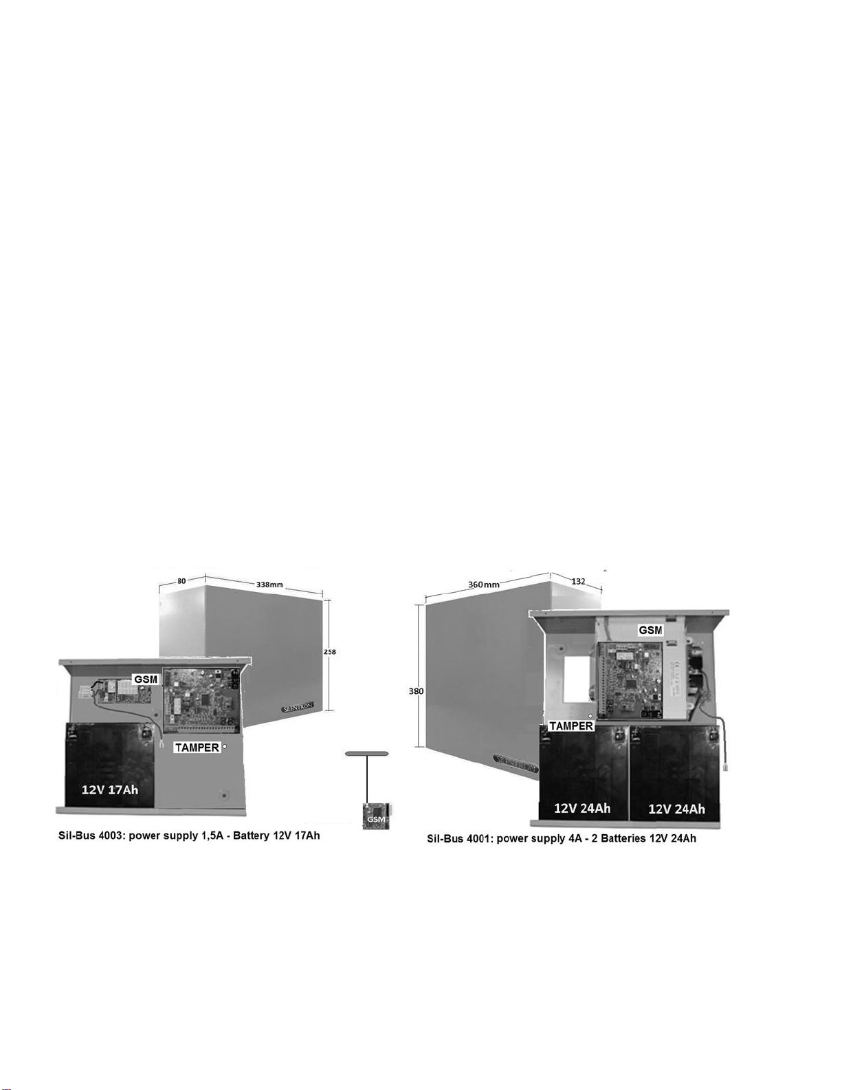
2.1 DIFFERENCES BETWEEN THE TWO CONTROL PANELS
Sil-Bus are extremely powerful control panels that may be used to develop small and large systems using from 1 to over 120 detectors. You can select one of the two available control panel
models based on the type and size of the system to be installed. The two models differ only for the control panel’s housing a nd its power supply which allows for a different number and type
of batteries (see figures) as well as different type and number of powered devices (see electric energy consumption table).
The specifications supplied in paragraph 7.4 must be taken into account because the different power supply and the resulting different installable batteries are clearly appropriate for
different sized systems.
3
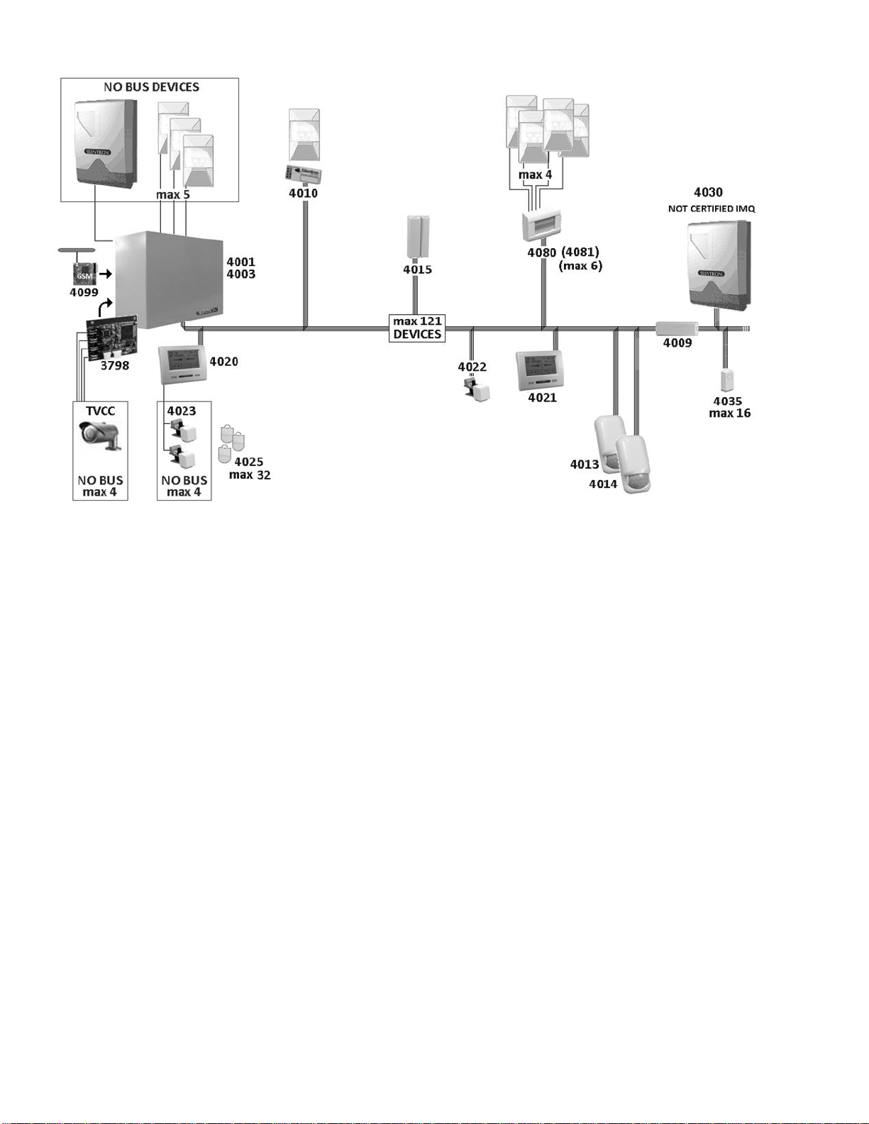
2.2 EXAMPLE OF A FULLY EXPANDED CERTIFIED SYSTEM
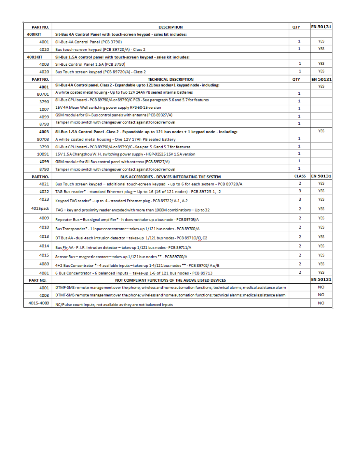
2.3 CERTIFIED SILENTRON PRODUCTS
Please find following a table listing IMQ certified products. This table also lists the main components of the control panels and th e special installation requirements of some components.
To show other compatibles devices, that are not EN 50131 certified, please see al page 27.
2.4 CONVENTIONAL HARDWIRED PERIPHERAL DEVICES
Control panels are fitted with lines that are not Bus to which you can connect:
Up to 5 detectors powered over 3 wire balanced line
no. 1 (or more) self-powered siren with built-in battery
no. 1 (or more) not self-powered built in siren
no. One 12V microphone for remote audio monitoring
no. 1 Management Card for 1-4 hardwired CCTV cameras (not certified accessory device)
Caution! The NOT BUS devices that comprise the system (alarm intrusion devices – those supplied by other manufacturers) must feature at least a Grade 2 certification in order not to
downgrade the overall system. The 4099 GSM module is certified as part of the over all system Cameras control board part no. 3798 is not part of the provisions foreseen by the EN 50131 -1
standard and its following amendments.
2.5 INSTALLER’S RESPONSIBILITY & PERFORMANCE
Each alarm system consists of several peripheral devices, detectors, sirens, control points, keyboards, etc. which are controlled by one of the control panels that are featured in thi s manual.
This manual describes all of the panels features, their use and their operation. A professional installer has the essentia l task of identifying which functions are required by the customer, to
foresee the safety measures required by the system and to install the system with diligence and professionalism. The installe r must integrate the instructions supplied in this manual with the
operating variables being implemented in the system in order to allow the user to fully master all of these functions.
2.5.1 INSTALLER AND USER AUDIO WIZARD
In order to facilitate the system’s implementation and use, these control panels feature an audio wizard that illustrates the available operations during their use. For this reason some
marginal and/or highly intuitive aspects of the control panels may not be mentioned in this manual. Control panels have been designed in such a way that no user operation could damage
the system.
2.5.2 MINIMUM SYSTEM REQUIREMENTS FOR EN 50131-1 AND FOLLOWING STANDARD COMPLIANCE
The system must foresee at least one control panel battery, a keypad with enabled built- in telephone dialer, a detector and an external siren (Grade 2 certified).
4
* Devices must be installed with tamper protection in order to comply with the standard.
** Terminal board’s NC not balanced inputs are not compliant and therefore not available.

5
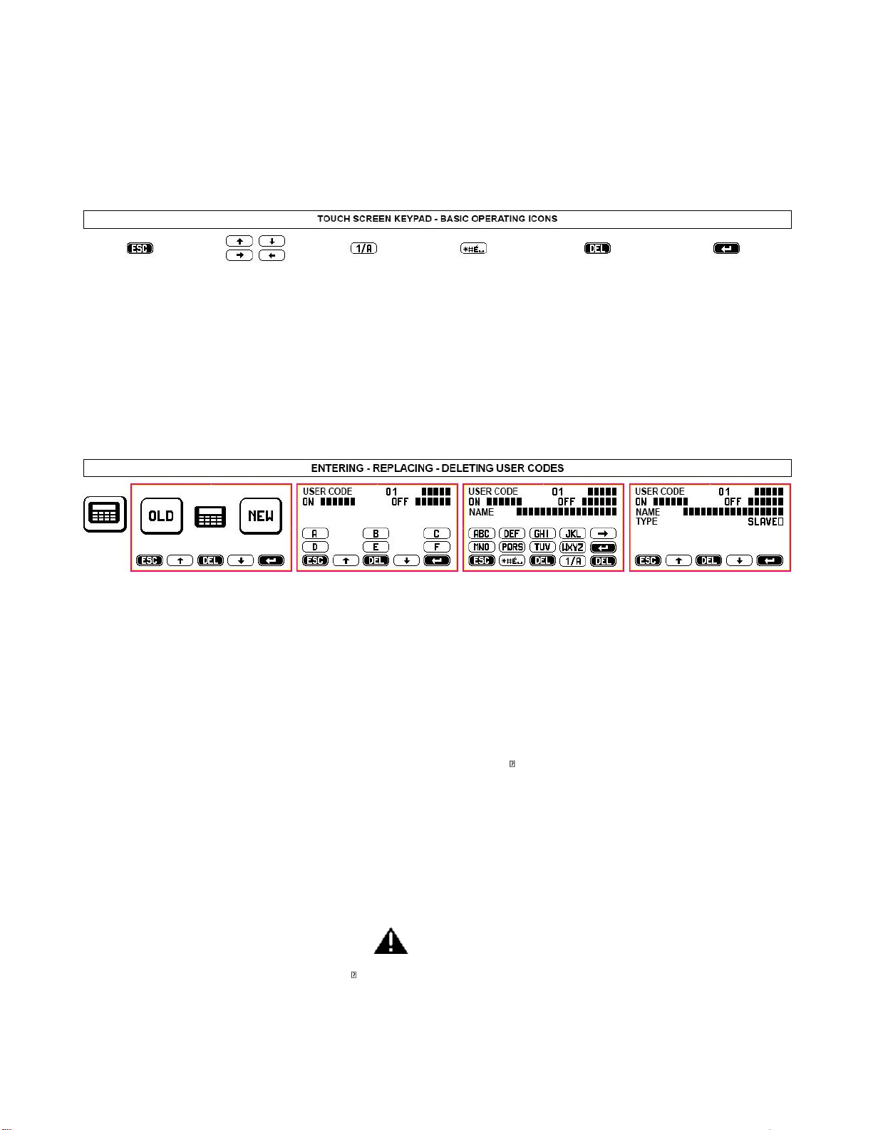
3 USER MANUAL : The following figures describe all of the operations that the user can perform on the control panel using tactile keypad part no. 4020. The figures s pecifically describe how
to partially and fully arm the system, how to test it and the user settings.
6
3.1 ACCESS CODES - Caution! Keypad locks for 3 minutes when the wrong code is entered more than 5 times!
ESCAPE: exit screen
without saving any
changes
move inside a screen or
exit writing mode
switch keypad operations
from letters to numbers
special characters
delete any changes that
have been made without
saving
confirm entered data
ALWAYS SELECT
AFTER HAVING MADE
ANY CHANGES
You must use 2 access codes, the USER code and INSTALLER code, in order to operate the control panel.
These different codes are programmed by the installer during the installation. After the installation, the user must change the temporary user code programmed by the installer to have full
system’s ownership. Any future changes made by the installer will need to be authorized by the user employing this new user code.
3.2 ACCESS LEVELS
Level 1: Control panel can be accessed by all: anyone can see the display’s basic screen
Level 2: User Access: user can access control panel by entering a MASTER user code (5 digits) or a SLAVE user code (see par. 3.4.2)
Level 3: Maintenance access: control panel's settings can be accessed only by entering the installer code
Level 4: Manufacturer access: control panel’s upgrading operations may be performed only when the cont rol panel is disabled.
3.3 MEANING OF ICONS
---------------------------------------------------------------------------------------------------------------------------------------------------------------------------
3.4 USER ACCESS DURING STANDARD CONDITIONS (only MASTER codes - see table 1)
TIME/DATE-DISPLAY: apply pressure to the center of the display and enter user code to access: fully arming mode, default partial arming mode (to arm zones previously set during system
installation) and selectable partial arming mode. The decreasing exit time (entry/exit delay after which control panel is armed) will display after selected arming procedure has been
performed.
TEST: use to test system’s components, beginning with the Bus network. Follow the instructions on the display.
INSTALLER ACCESS: used to enter installer code and to service control panel.
3.4.1 SETTINGS: some operations, such as setting the control panel’s clock or setting the display, are intuitive and simply require that you follow the text and audio prompts. Please find
following a description of the other operating procedures:
3.4.2 REPLACING/CREATING USER CODE (up to 32) – please see par. 9.1 - 9.1.1 and above figure.
The USER code, which allows you to access the control panel, may be MASTER or SLAVE. You are enabled to perform all of the pr ocedures described in the User Access Tables when you use
the MASTER code. The SLAVE code gives you access only to the previously enabled zones.
After installation is complete, user may access the control panel with the user code set by the installer to change it so that it is not known even to the installer. You can also add and/or
delete other third party codes, restricting operations to specific zones where they are necessary (e.g. A + B + C arming, A + B disarming - any possible combination of the above The user will
authorize installer’s access for servicing by entering his user code.
3.4.3 ISOLATING (EXCLUDING) a detector (only with MASTER codes). When necessary, in the event of failure for example, one or more detectors may be excluded. Please see the following
table for the relevant instructions.
INCERT - Detectors' isolating : the installer only, with his code, can isolate one or more detectors when it's necessary. The operation will be signalized by the vocal message 2 (please, register
as "Periferic device isolation") and SMS 2 (automatic text inside).
3.4.4 DISPLAYING EVENT HISTORY LOG (only with MASTE R or INSTALLER codes - see also table at par. 8)
Press the event history log icon to displays the control panel’s last 500 events. Events are displayed showing (↓ ) event’s date and the device that triggered the event. Voice calls and SMS
messages are displayed as follows:
VOICE CALL . (type of message) 1-10 ; (result) OK/NO/OCC (busy) – Dialed number – Name. Examples:
VOICE CALL . 1 OK 333444555 Gianni SMS TRANS. - 1 OK 333444555 Gianni
VOICE CALL .[RESULT] –[TYPE] - PH NO. COMISSIONING – LABEL
DETEC. ESCL. – bathroom OPEN WINDOW/DOOR – main entrance
START Firmaware (reboot after a total disconnection) Upgrade firmware (reboot when a new FW is placed)
3.4.5 ARMING WITH USER CODE (with both Master and Slave codes - see table 1)
Enter the user code and press the relevant icon to fully or partially arm the control panel. Partial arming zones are set dur ing system’s installation. Press SELECTABLE ARMING to arm
different zones, then select items to be armed. You can also set an arming delay time as well as conditions where partial arming is blocked - see par. 3.5.1.
3.4.6 AUTOMATIC ARMING: see par 10.1.2 when automatic arming has been set during installation.
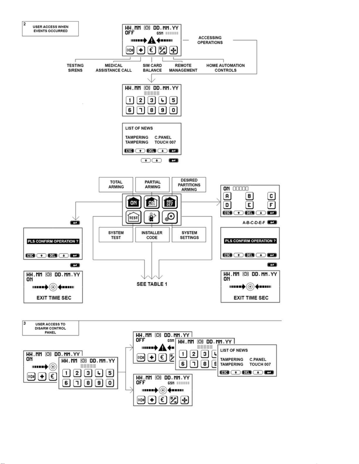
3.5 USER ACCESS WITH NEW EVENTS (only with MASTER codes - see Table 2).
The "warning" icon displays when new events to be verified have occurred. The different type of events (alarm, masking, tampe ring, failure, etc.) are clearly described for the user to read.
Events that are no longer taking place are deleted when the user confirms that same have been read. Events that are still occurring will not be deleted.
INCERT - Tamper Alarm: the installer only, with his code, can force the arming and/or replace the system.
7

8
3.5.1 ARMING DELAY - Caution: in the following circumstances, control panels may not arm!
An arming delay ranging from 1 to 99 seconds is set during the installation. During this preset time the control panels check the system’s condition and a “warming” icon will display if any
detector has triggered an alarm. Should an alarm have occurred, you will need to read the event from the even history log after having entered the a ppropriate code. You can force control
panel’s arming by confirming this option ( ) in which case all detectors that are not alarmed will be enabled.
Arming is denied and the condition is displayed on the keypad if one or more detectors are alarmed during arming delay.
Caution! We therefore recommend that you wait for the system to successfully arm before leaving the premises.
Caution! Forced arming may be performed only using the keypad and only by entering the MASTER code. When arming is blocked, you must remove the cause of the blocking before you can
arm the system again.
3.5.2 DISARMING
You must enter the user code to disarm the control panels. Any occurring alarms will end when the system is disarmed. Check any new occurring events.
If any detector has been set with an alarm delay (adjustable from 1 to 45 sec.), same will trigger an alarm unless the contro l panel is disarmed in the meantime. An immediate alarm will take
place when a detector with an alarm delay detects a movement and a second detector without an alarm delay is also triggered. In this case, telephone transmissions will begin after 30
seconds or, when set for a longer time, after entry/exit delay time.
3.6 TAG ARMING/DISARMING
Control panels can also be controlled by a small electromagnetic key, called a TAG. Each TAG is supplied with more than 1000 million code combinations and operates by simply bring it c lose
to the reader. 4020 a nd 4021 keypads feature a built-in reader which is located on the top right hand side. This reader is pulse operated and each reading either arms or disarms the control
panel. The keypad reader does not supply any other function other than arming or disarming.
3.6.1 OPTIONAL TAG READERS
The system may foresee additional TAG readers (part no. 4022 which is bus operated or part no. 4023 which is hardwired to the keypad) whose sensitive element is located in the front
section (see relevant instructions). The above readers supply the following functions:
ON - full arming: bring the TAG close to the reader and remove it as soon as the red LED indicator turns on.
ON/P - partial arming: bring the TAG close to the reader and remove it as soon as the red LED indicator begins to flash.
OFF - disarming: when the control panel is armed, bringing the TAG close to the reader and hold it there until the green LED indicator turns o n.
Yellow LED: these readers feature a yellow LED indicator. If the yellow LED indicator flashes when the system is being armed (ON - ON/P) it reports that there are open windows/doors
and/or alarm events taking place. In this case, close the open windows or try to force arming using the keypad. If the LED f lashes after disarming, it means that an alarm has occurred during
arming period and that you must therefore display the event history log.
Caution! Red, green and yellow LED indicators can be programmed to stay on or to switch off after 30 seconds in order not to d isplay system’s condition. The LEDs will turn on again when
you bring an enabled TAG near them if they are setup to switch off.
3.6.2 DISARMING UNDER THREAT - DURESS ALARM
TAG reader can be programmed to require that USER code is also entered on the keypa d within 30 seconds from disarming. With this setup, the system will continue to be disarmed even
when the code not be entered within 30 seconds, but the control panel will send a preset ROBBERY message over the phone line enabling a silent alarm. This feature is useful if you run the
risk of being forced to disarm the system against your will.
3.7 SPEED DIAL COMANDS NOT REQUIRING CODE ENTRY (see Tables 1 and 2)
The user can enable these functions for different needs by simply pressing the relevant keypad icon.
Caution! Functions 3.7.1/2/4/5 are not IMQ compliant.
3.7.1 TESTING SIREN: press once to enable sirens, press again to disable them. This function can al so be used as a neighborhood alert. Sirens will be silenced automatically after the preset
time when they are not previously manually turned off.
3.7.2 MEDICAL ASSISTANCE: press and hold icon for 2 seconds to enable preset emergency telephone calls.
3.7.3 SIM BALANCE: press and hold icon for 2 seconds to enable the call to request SIM remaining balance to SIM provider.
3.7.4 REMOTE MANAGEMENT: press and hold icon for 2 seconds to enable electronic connection with the installer (if foreseen).
3.7.5 HOME AUTOMATION FUNCTIONS (controlling electric charges):
Control panels can be used to control any type of electric device (automations, lights, engines, etc.), through the built-in relay or the keypad using the appropriate boards part no. 4035 Relay
Bus and by confirming operation. The installer must clearly describe the functions that are shown on the display since these vary greatly from one installation to the other.
Commands are simple to use and can be performed in different ways using:
the system’s touch-screen keypads that display which controls to execute. Identify the actuator by making
phone calls followed by number combinations corresponding to the required commands (see par. 3.8.1)
especially written SMS messages (previously stored to be retrieved using the phone – see par. 3.8.2)
specific APP downloadable from website www.silentron.com and programmable on the user’s SMART PHONE.
3.8 REMOTE REQUESTS AND CONTROLS - Caution! The functions described in this paragraph are not IMQ compliant as same are not foreseen by the standard.
3.8.1 Accessing the control panel using the landline (PSTN) number – Only with audio wizard message recording.
Dial the number - wait for two rings - hang up - dial the number again within 1 minute. The control panel answers using the audio wizard message recording followed by a beep. Dial the
USER code followed by # to open the connection with the control panel. Continue as follows:
3.8.1.1 Sending commands the control panel. Press the following keys to send the corresponding command to the panel: it will reply with an audio message.
check control panel's ON-OFF condition 0 # arm control panel 0 * 1 #
arm only A+B zones 0 * 2 # disarm control panel 0 * 0 #
INCERT - Note ! The remote arming/disarming will be confirmed by 3 beeps/arming and 1beep/disarming to the first number on the phone book.
3.8.1.2 Sending commands to the control panel’s relay. Press the following keys the send the corresponding command. The control panel will reply with one or more beeps
check relay status 20 # relay is enabled = 3 beeps - relay is disabled = 1 beep
enable relay 20 * 1 # 3 beep
disable relay 20 * 0 # 1 beep

9
3.8.2 Accessing the control panel using the mobile network (GSM)
The numbers stored in the control panel’s address book by the installer can be programmed allowing their direct access or not as long as the dialing number is not anonymous.
a) Making a call from a number that is recognized and enabled for direct access. Dial control panel’s SIM card number, the control panel answers using the audio wizard message recording
(when same has been recorded) followed by a beep or by an immediate beep. You are connected to the control panel and can perf orm the following described operations once you hear this
beep.
b) Making a call from a number that is not enabled for direct access. Dial control panel’s SIM card number, listen to audio wizard message recording (when same has been recorded)
followed by a beep. Enter the USER code followed by # after hearing the beep. You are now connected to the control panel and can perform the required operations.
Operations. Press the same key combinations used when calling from a PSTN line (see above) to check control panel and to perform operations.
INCERT - Note ! The remote arming/disarming will be confirmed by 3 beeps/arming and 1beep/disarming to the first number on the phone book.
3.8.3 SENDING COMMANDS VIA SMS (only when calling from a number enabled for a direct access)
You can control the control panel using SMS messages. The control panel may not receive these commands immediately since same are subject to the SIM card's provider transmission
service. Caution! ײַ = space
3.8.3.1 Controlling the control panel via SMS
operation SMS text to send control panel's SMS reply
check control panel's ON-OFF condition C? ON ײַ OK ON ײַ ACF(zones) ײַ OK OFF ײַ OK
fully arm control panel ON ON ײַ OK
partially arm zones ON ײַ ACF(zones) ON ײַ ACF(zones) ײַ OK
disarm control panel OFF OFF ײַ OK
read event history log MEM? last 3 events displayed in the event history log
request SIM card balance ? € according to SIM card's provider mode
INCERT - Note ! The remote arming/disarming will be confirmed by 3 beeps/arming and 1beep/disarming to the first number on the phone book.
3.8.3.2 Controlling control panel's built-in relay
operation SMS text to send control panel's SMS reply
check R? R ײַ ON (OFF)
enable R ײַ ON R ײַ ON ײַ OK
disable R ײַ OFF R ײַ OFF ײַ OK
3.8.4 Controlling system's Bus relay boards 4035
These boards can be managed only through the touch screen keypad (see par. 3.7.5) or via SMS (if GSM module has been installe d). For easier operations, you can use APP icons that replace
sending SMS messages.
Caution! You must transmit the number of the Bus node corresponding to the setup relay board (for example:32).
operation SMS text to send control panel's SMS reply
manage 32? 32 ײַ ON (OFF)
enable 32 ײַ ON 32 ײַ ON ײַ OK
disable 32 ײַ OFF 32 ײַ OFF ײַ OK
3.8.5 REMOTE AUDIO MONITORING
Install and connect to the control panel a remote microphone to perform remote audio monitoring. Press during a phone call to hear what is happening where the microphone has been
installed. Two way conversations are not possible.
3.8.6 EDITING PHONE NUMBERS IN THE CONTROL PANEL'S PHONE BOOK
Edit one or more phone numbers stored in the control panel's phone book by sending the following SMS message: A old number A new number (without any spaces in between). Reply:
number HAS BEEN CHANGED
3.9 ALARM MODES
Once enabled, the control panels are always operational to assure tamper protection. You can temporaril y disable tamper protection only by enabling TEST mode. Enter the INSTALLER code
to enable TEST mode (maintenance - see. par. 19). Enabling TEST mode by entering the USER code does not disable tamper protection functions.
Operating modes: intrusion alarm zones
a) Disarmed control panel OFF only 24 hour zones, direct and automation controls are enabled
b) Partially armed control panel ON/P also armed intrusion alarm zones are enabled
c) Fully armed control panel ON all zones are enabled
3.9.1 ALARM MODE, REPORT AND MANAGEMENT
The keypad does not display any alerts during fully armed or partially armed mode. The event history log icon prompting to check the log can instead display when the control panel is
disarmed or during disarmed mode (see par. 3.5).
The foreseen alarm devices, telephone calls/preset text messages are activated when an alarm event takes place. Disarming the control panel stops any alarm and/or telephone call, apart
from digital ones to the central monitoring station which cannot be blocked until the end of the cycle (contact central monitoring station’s staff if alarm is triggered by mistake).
Warning! Telephone messages are sent only if they have been properly enabled, assigned and recorded or written (Installation).
3.9.2 INTRUSION ALARM FUNCTIONS
Foreword: all detectors and alarm delayed detectors in the system can be set with a 1 to 99 seconds arming delay. Alarm delayed detectors will trigger an alarm after the time set during
installation (adjustable from 1 to 45 seconds). Arming delay allows user’s entry/exit when the keypad is installed in a protected zone within the premises. The following alarm modes take
place when the system is fully or partially armed.
3.9.2.1 IMMEDIATE ALARM: alarm devices (sirens and/or other) and text/audio alarm phone messages are activated when a detector set for an immediate alarm is triggered. The alarm lasts
for an adjustable time (from 1 to 999 seconds) and can be repeated over time if a new event is triggered by a detector.
3.9.2.2 DELAYED ALARM: the alarm delay time count down begins when a detector set for a delayed alarm is triggered. The alarm will activate at the e nd of the delay time unless the control
panel is not previously disarmed. Telephone messages are sent only at the end of delay time when delayed alarms are triggered. See 3.5.2.
3.9.3 TECHNICAL ALARM FUNCTION - Not EN 50131 compliant
A technical alarm is triggered by smoke, gas, flooding detectors when these events take place in the setup zones. These detectors are always enabled, regardless the control panel's
condition. This alarm only displays a "warning" alert during disarmed mode.
Caution! Alarm disabled! Every detector is automatically excluded after 3 alarms have occurred during a continued period in which the control panel is fully armed or partially armed. A
disabled detector is reset when the control panel is armed again.

10
3.9.4 PROTECTION FUNCTIONS OF THE SYSTEM
TAMPER: this function constantly monitors all of the system's components and its hardwired lines reporting any sabotaging attempts. All visual, audio and communication devices are
activated triggering a general alarm when tamper takes place and the control panel is armed . The "warning" icon displays and telephone calls are dialed without any other audio alarm
taking place when the control panel is disarmed.
MASKING: the masking protection function is supplied by any anti-masking detectors that may have been connected to the Bus. All visual, audio and communication devices are activated
triggering a general alarm when masking takes place and the control panel is armed. The "warning" icon displays without any other audio alarm taking place when the control panel is
disarmed.
INCERT - Caution ! The reset of anti-tamper/masking alarms will be possible by the installer only
BUS FAULT: this function constantly monitors the Bus line to which all of the system's components are connected. When the control pane l is armed any detected bus faults trigger a cycle of
telephone calls without activating any audio alarm.
TELEPHONE FAULT
PSTN line: the landline is constantly monitored. When the system detects that there is not line or that a fault has occurred for more than 10 seconds, this is displayed on the keypad
and reported via GSM (if available).
GSM line: when the GSM board in installed, any fault on the GSM line is displayed and reported after 15 minutes using the PSTN landline. When line is reset, the system sends SMS
messages confirming GSM's availability.
SUPERVISION CALLS: the control panels call and transmit monitoring messages every 1-25 hours (adjustable).
The first number stored in the control panel’s phone book will be dialed to send a 3 second beep when the PSTN line is the only operating one. When also the GSM line is operational, preset
no. 5 SMT will be sent to the preset phone numbers stored in the phone book.
230V POWER FAILURE/POWER RESTORED: any power failure is displayed after 10 sec onds. If failure persists for more that preset time (adjustable f rom 1 to 60 min.), telephone calls will be
made and SMS will be sent. The system immediately reports when 230V power is restored.
LOW BATTERY: batteries are monitored only when there is not power available. Low battery visual/audio alerts are displayed on the keypad and audio/SMS messages are enabled after 10
seconds. The system reports a low battery level when battery is below 10.9V. Battery level is restored with a 11.2V charge. Temporarily disconnect the control unit from the power line to
check battery level.
OPEN WINDOW/DOOR: the system reports any passage that has been left open. These events are logged in the event history log and can be displayed after having entered the USER code.
Open windows/doors prevent control panel from being armed. You must force arming or close windows/doors that have been left often in order to arm the system.
4. ALARM MESSAGES SENT BY THE CONTROL PANEL : acknowledgement pass-trough
During an alarm the control panel will call all the numbers has been stored in the phone book and jointed to the alarm event, as described above.
Caution ! The called user must confirm the reception by pressing a number on his phone. Without this confirm, the call will be stored as "unreceiv ed" on the panel memory.
Digital message to the central monitoring station: this message has priority over any other transmission. Completing
this function may take a few minutes, as long as it takes for the surveillance staff to reply.
Caution! This is the only type of message that is not disabled by disarming the control panel.
SMS messages: alarm SMS are sent by the control panel when the GSM module is available. SMS message transmission is stopped when the control panel is disarmed.
Audio messages: the control panels dial every setup phone number in sequence and transmit an audio message. W hen both GSM and PSTN landline are available, you will select which
line has priority during system's setup. If a number does not reply or is busy or without reception confirm, each number is dialed up to three times after the first sequence of calls has
been completed. The control panel will stop dialing when it is disarmed, but the digital calls to Security cannot be stopped.
Disabling calls remotely: press # af ter having heard the “end of message” beep to disable additional calls.
5. NOT EN 50131 COMPLIANT SPECIAL FUNCTIONS
Control panels supply some complementary functions which may be useful to the user based on the individual system.
5.1 Detectors and Bus relay board 4035 (CHIMES - HOME AUTOMATION FUNCTIONS)
Each detector can control one or more Bus relay boards 4035 when the control panel is armed and/or disarmed. It can, for example, automatically turn lights on, enable a door bell or other
similar automations.
5.2 Controlling Bus relay boards 4035 with a TAG ( ACCESS CONTROL FUNCTION)
An access control system can be implemented using special TAGs that differ from those used to arm/disarm the control panel. The TAG will allow to open doors, gates, etc. through a Bus
relay board and each access will be stored in the event history log listing entry time and date.
Caution! This use requires to frequently display/ download the event history log based on the number of accesses that typically take p lace.
5.3 TTL Connections
The control panel can be connected to other devices using a TTL port. Through a Silentron proprietary protocol, this port allows different devices to communicate with eac h other and to
centralize alarms transmitted by different control panels. Please contact Silentron's Technical Department to use this function and to receive its operating instructions.
6. USER INFORMATION
This manual comprehensively describes Sil-Bus Control Panels' extensive capabilities. Many functions are tied to the way in which the system is installed, its setup and its appropriate
maintenance. The installer must supply any integration to this manual that will allow the user to achieve the described operations.
Although Silentron is available to provide information and advice upon request, it declines any responsibility regarding for the use and/or lack of use of the significantly varying uses that are
made possible by the equipment. Specifically:
a) malicious events that are not reported or that are insufficiently reported which could occur for a variety of causes, such as defective or insufficient charging of the batteries, alarm
devices' shortcomings, lack of adequate SIM card funds, inability to connect to the telephone line, mistaken selection/positioning of employed det ectors, failure to arm the system, other
fault reports that are not corrected, etc. (the list is merely indicative and not comprehensive);
b) false alarms There are two types of false alarms: a) false alarms due to failure of system components, b) improper alarms caused by various types of environmental factors and/or
installation errors. The manufacturer's warranty applies according to the terms and conditions published online and in the general catalogues in the event of proven flawed material. The
dealer/reseller who sold and installed the product to the user is responsible for finding a solution in the event of unflawed materials.
c) partial or total lack of the described functions: this manual describes the Sil-Bus control panel including all of its accessories and/or peripherals; any shortcomings are therefore due to an
incomplete installation, settings and/or function enabling. Silentron's technical staff is available to assist in this regards.
For additional information please visit www.silentron.com
 Loading...