

Page 1

User Manual
Page 2

Page 3

Thank you for purchasing the USB from the OMNI series. The OMNI USB is an Battery Powered,
Optically Isolated USB Hub.
• Dedicated dual-bre 10G/1.25G optical isolation ensures noise-free data transmission
• Three ANC-enabled USB Pure Port; additional two dedicated power supply port
• Dual-head USB cable compatible for fully isolated power and data connections
• High-capacity 8,000mAh battery with a battery only mode, isolating power from both the source and mains
• BMS with charging optimisation to extend battery lifespan
• Fast charge with PD3.0 – quick charging passthrough for connected source device
• 10MHz synchronous clock input for precise timing accuracy
• Digital-to-Digital Conversion with Hi-Res 24/192kHz Coaxial and Optical S/PDIF outputs
• Normal and Enhanced Coaxial outputs to suit your DAC
• Real-time display of voltage, current, power and noise – for each USB port
• Ultra-Speed USB 3.2 for rapid data transfer rates up to 10Gbps
• NEXIS app compatible for wireless remote control and OTA firmware updates
1
Page 4
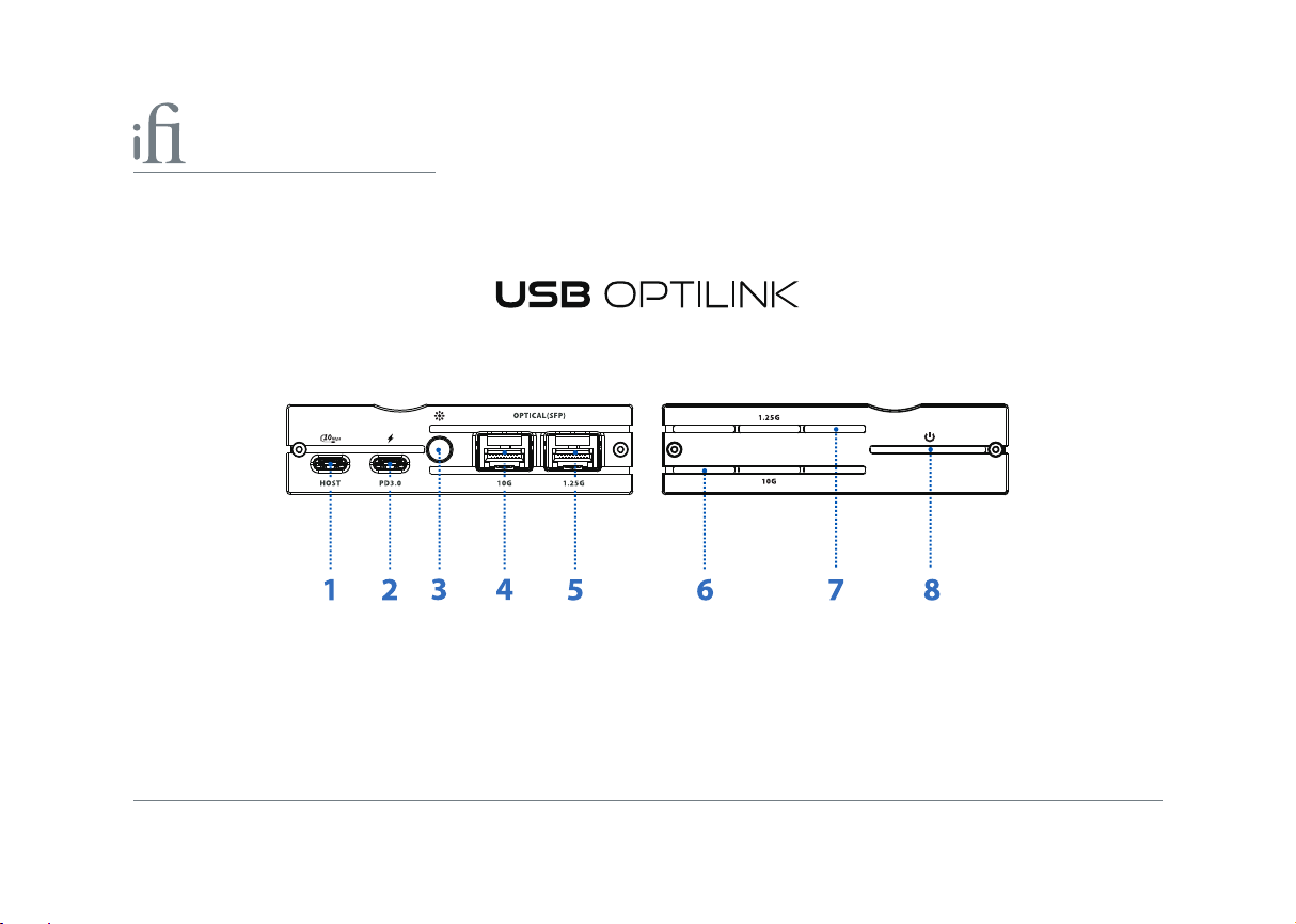
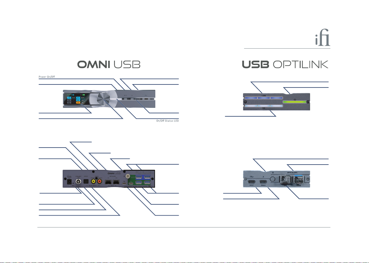
1.
USB-C Host port
2.
USB-C PD3.0 Fast Charging
LED brightness control
3.
SFP 10G Optical Fibre Output port
4.
2
port
SFP 1.25G Optical Fibre Output port
P. 3
P. 3
P. 4
P. 4 P. 5
5.
SFP 10G Optical Fibre Output Connection Status LED
6.
SFP 1.25G Optical Fibre OutputConnection Status LED
7.
Power connection status LED
8.
P. 4
P. 4
P. 5
Page 5

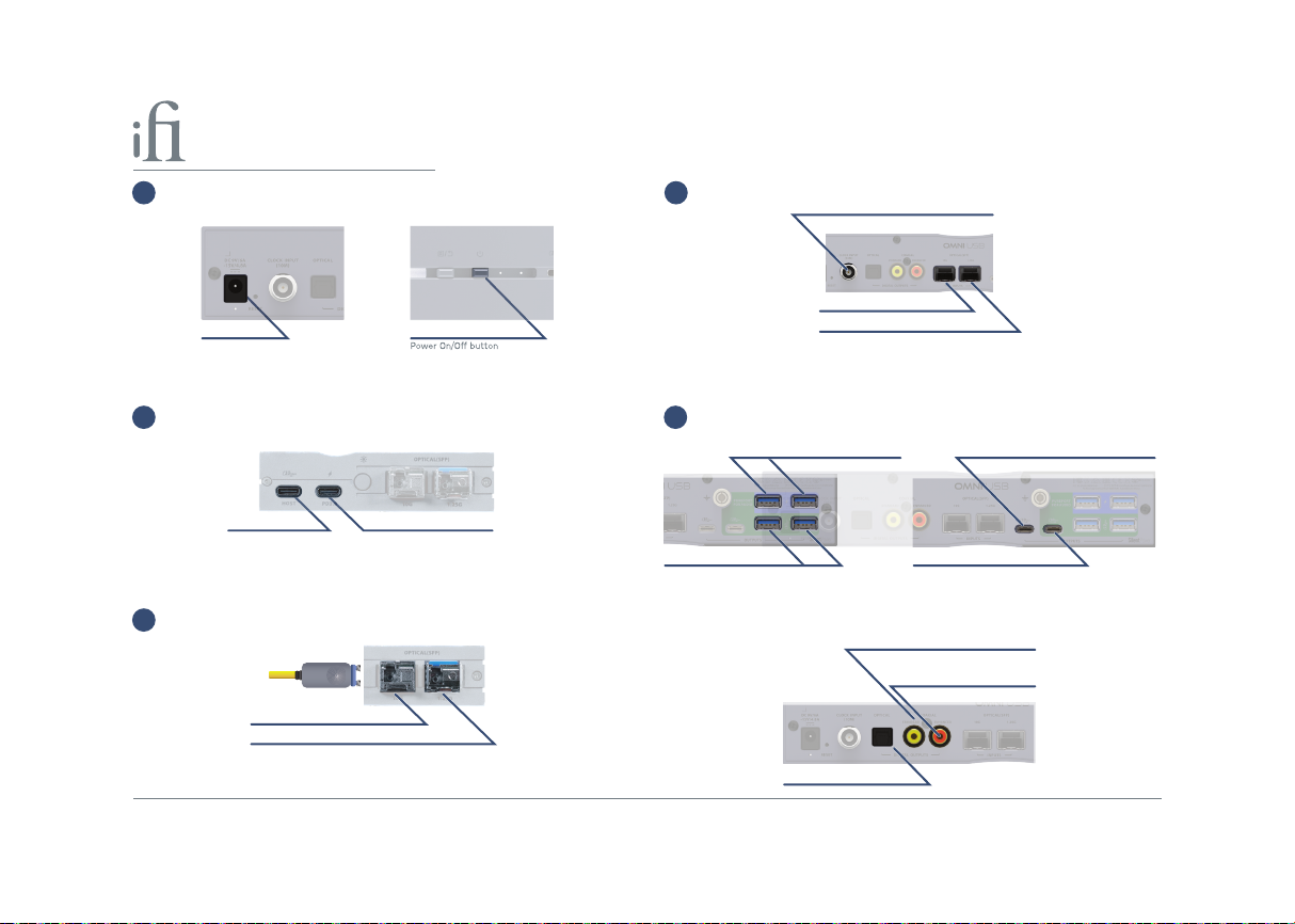
1. USB-C Host Port
a. Use the included USB-A to USB-C or USB-C to USB-C cable to connect the source device's USB output port to the USB
OptiLink's 'Host' port. The source device will supply both a digital signal and power to the USB OptiLink, provided it can
output sucient current.
b. Next, connect a PD3.0 (2) power supply. It provides the necessary power for the USB OptiLink, while also supporting
passthrough fast charging for the source device.
Tip: If the standalone power supply (2) is not used, the source device must be able to provide a minimum rated 5V/2A continuous current, as the USB OptiLink will
not function properly with a minimum operating power requirement of 5V/2A.
2. USB-C PD3.0 Fast Power input Port
If your source device cannot meet the power requirements of USB OptiLink, you can use a common USB-C power
adapter 5V/2A (maximum power 10W) to power it.
If you want to quickly charge the source device, connect the USB OptiLink to a PD USB-C power adapter (20V/5A,
maximum power 100W) that support the PD3.0 charging protocol.
Tip: The above USB-C power adapter is not included in the OMNI USB accessories list and needs to be purchased separately.
3
Page 6
3. LED brightness control
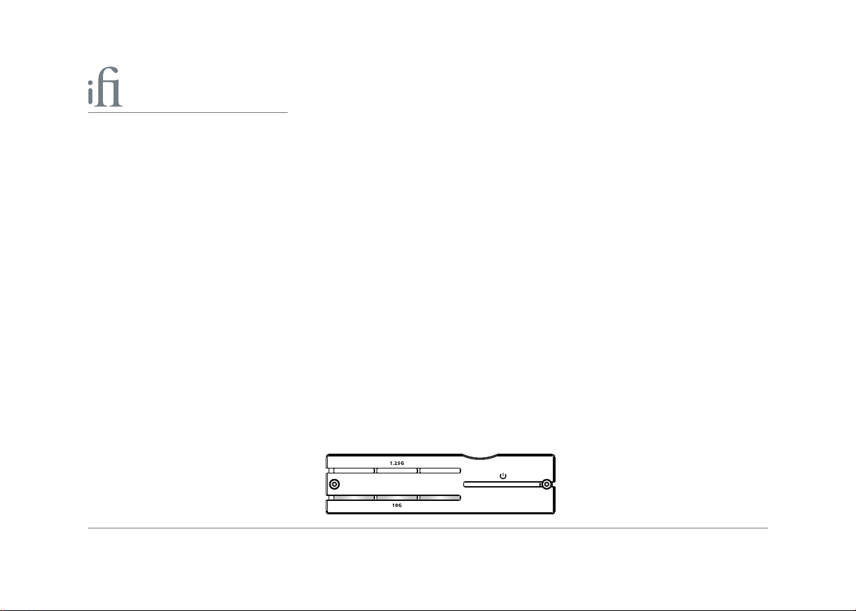
This button adjusts the brightness of the front panel connection status LEDs (6,7,8). The default setting is 'Bright'.
Short press this button to cycle the LEDs (6,7,8) through three modes: bright, soft and o.
Bright ‘Bright’ brightness mode. The LED brightness always remains bright.
Soft ‘Soft’ brightness mode. The LED brightness always remains soft.
O ‘LED’ will turn o.
4. SFP 10G Optical Fibre output port
This is the SFP 10G optical output port. Please plug the supplied USB OptiLink 10G bre optical module into this port.
Tip: The USB OptiLink 10G SFP bre optic modules are factory-tted to the USB OptiLink bre optic module port.
5. 1.25G SFP Optical Fibre output port
This is the SFP 1.25G optical output port. Please plug the supplied USB OptiLink 1.25G bre optical module into this port.
Tip: The USB OptiLink 1.25G SFP bre optic modules are factory-tted to the USB OptiLink bre optic module port.
6. SFP 10G Optical Fibre connection status LEDs
The LEDs show the current SFP 10G optical connection status of the USB OptiLink.
LED Status
White Connected
O Unconnected
4
Page 7
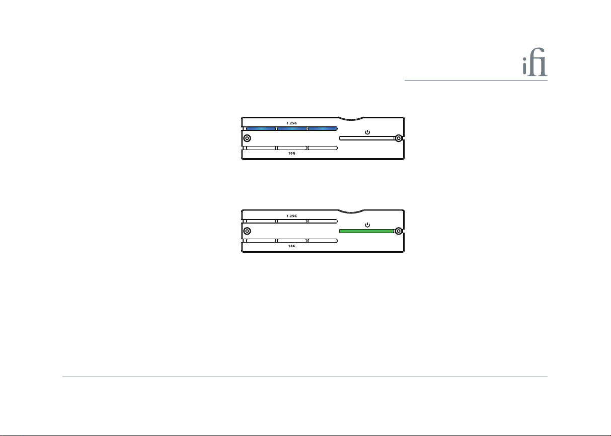
7. SFP 1.25G Optical Fibre connection status LEDs
The LEDs show the current SFP 1.25G optical connection status of the USB OptiLink.
LED Status
Blue Connected
O Unconnected
8. Power Connection Status LED
The LEDs show the current power connection status of the USB OptiLink.
LED Status
Green Connected
O Unconnected
5
Page 8
5
7
1
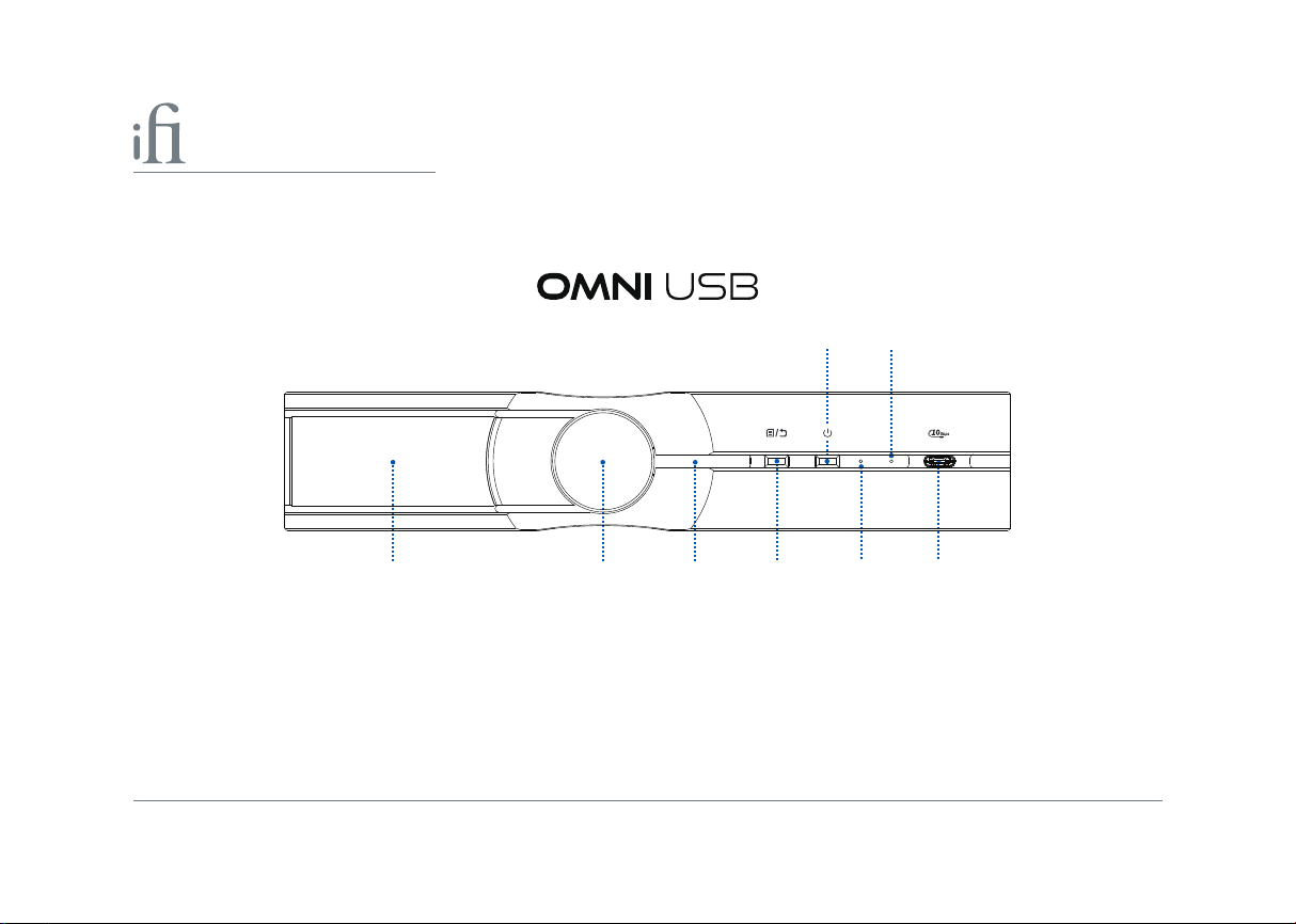
1.
TFT Display
2.
Multi-function Dial
Power On/O LED
3.
Enter/Exit menu settings
4. Standard USB-C port8.
6
2
P. 8
P. 8
P. 8
P. 8-16
43
Power
5.
6.
7.
On/O
SFP 1.25G Optical bre module connection LED
SFP 10G Optical bre module connection LED
6
8
P. 17
P. 17
P. 17
P. 18
Page 9
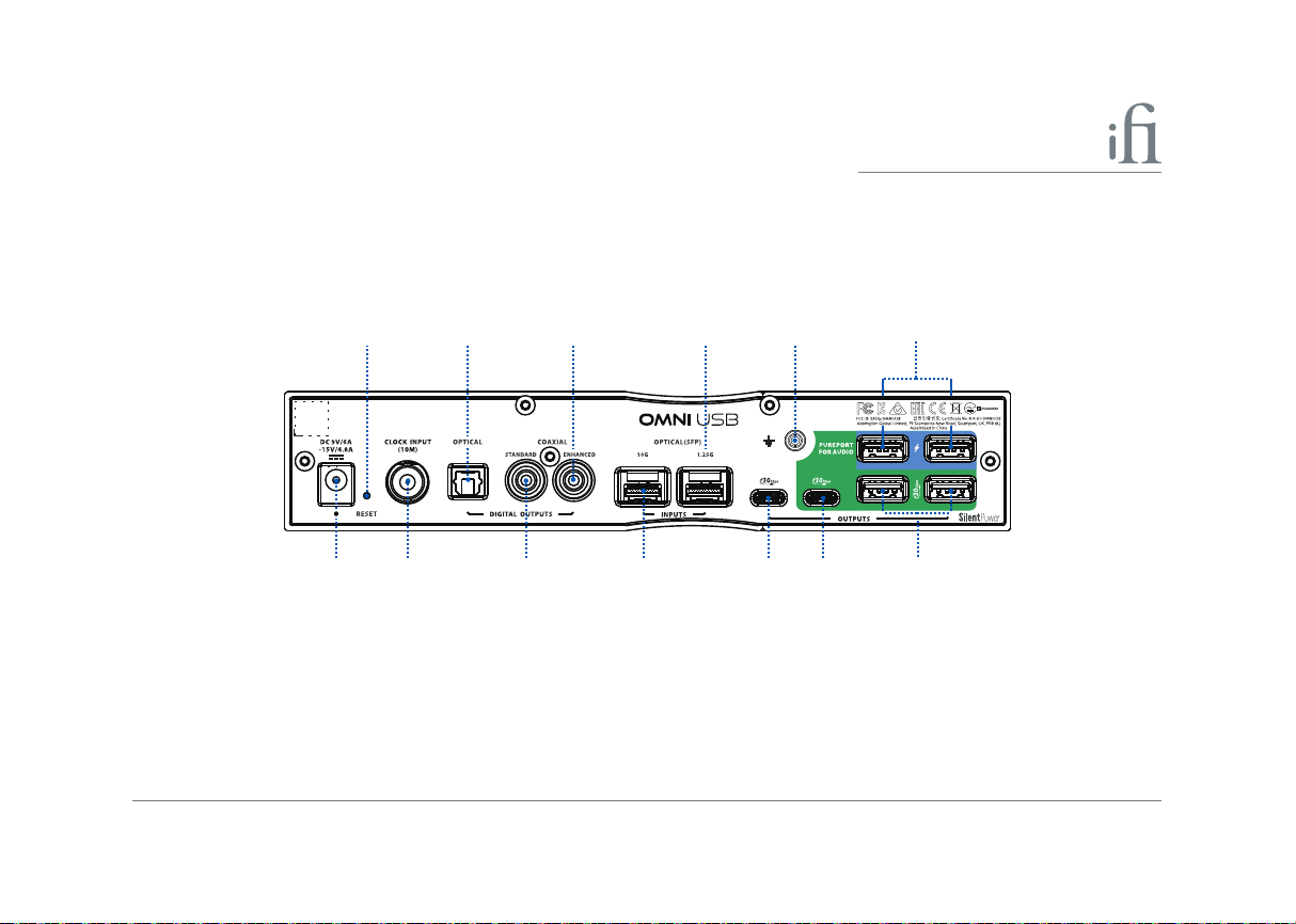
10
9
12 14 16 18
11 15 17 21
13
20
19
9.
DC power supply and battery charge input port
10.
Factory Reset
11.
External Clock input port
12.
S/PDIF Optical Output
Standard S/PDIF Coaxial output
13.
Enhanced S/PDIF Coaxial output port
14.
SFP 10G Optical bre input port
15.
port
port
P. 18-19
P. 19
P.19-20
P. 20
P. 20
P. 20
P. 21
SFP 1.25G Optical Fibre Input Port
16.
STANDARD
17.
18.
Grounding Terminal
19.
PurePort USB-C Data and Power output port
20.
PurePort 2 x USB-A Power output ports
PurePort 2 x USB-A Data and Power output ports
21.
iFi Nexis App QSG SPECIFICATIONS
USB-C Output port
P. 21
P. 21
P. 21
P. 22
P. 22
P. 22
P. 23-31
7
Page 10
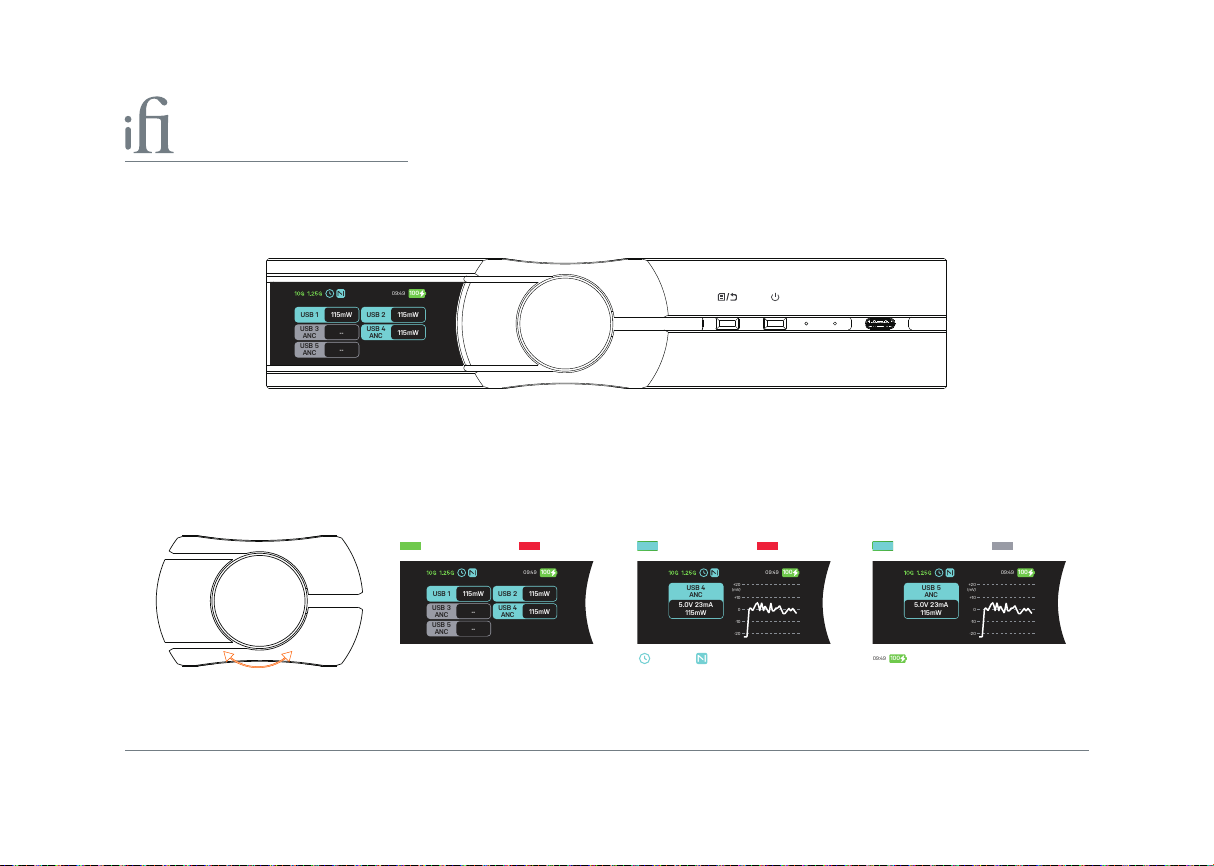
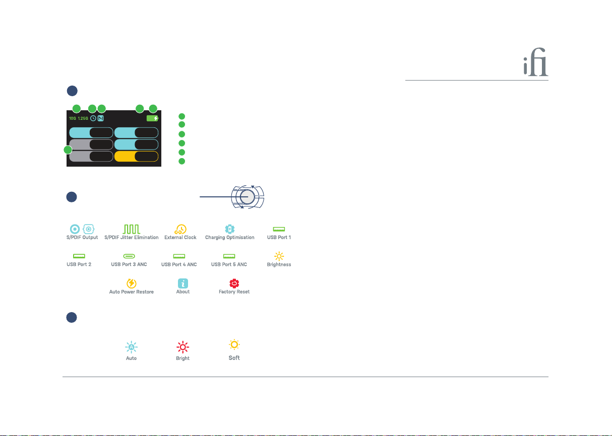
1. TFT display
09:49
10
0
USB 5
ANC
--
USB 4
ANC
115mW
USB 3
ANC
--
USB 2
115mW
USB 1
115mW
09:49
10
0
USB 5
ANC
--
USB 4
ANC
115mW
USB 3
ANC
--
USB 2
115mW
USB 1
115mW
09:49
10
0
0
-
10
-20
+10
+20
(mV)
5.0V 23mA
115mW
USB 4
ANC
09:49
10
0
0
-
10
-20
+10
+20
(mV)
5.0V 23mA
115mW
USB 5
ANC
09:49
10
0
The TFT display shows the user interface in real-time: SFP 10G/1.25G optical input, external clock input, NEXIS application
connection, battery charge, battery charge duration, USB port voltage, current, power and noise.
Tip: The TFT screen should be on the left-hand side when OMNI USB is positioned horizontally, and at the top when positioned vertically.
2. Multi-function Dial
a) On the home page, turning the rotary ial switches the information displayed on the display, such as the individual
standards and the voltage, current, power and noise of the pure port USB port.
Connected Unconnected
Connected
Unconnected
10G and 1.25G SFP Optical Connection Status Clock and NEXIS Connection Status Remaining battery time/Battery status
b) Once you're in the menu, turn the rotary dial to scroll through the options. Press it to select or switch your choice.
8
Connected
Unconnected
Page 11
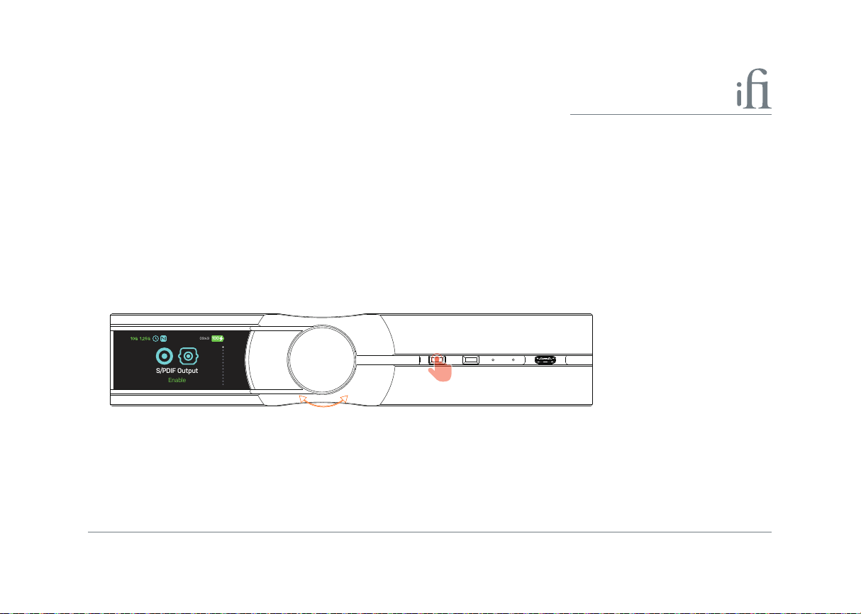
3. Power On/o LED
09:49
10
0
S/PDIF Output
Enable
This LED lights up when the unit is on and turns o when it's powered down.
4. Enter/exit menu settings
Short press to enter or exit menu settings and return to the homepage.
- S/PDIF Output - S/PDIF Jitter Elimination - External Clock - Auto Power Restore
- Charging Optimisation - USB Port 1 - USB Port 2 - USB Port 3 ANC
- USB Port 4 ANC - USB Port 5 ANC - Brightness - About
- Reset
Turn
Short Press
Tip: Turn to select function, short press to conrm selection or toggle on/o mode. If there is no operation within 10 seconds, the display will
return to the home screen.
9
Page 12
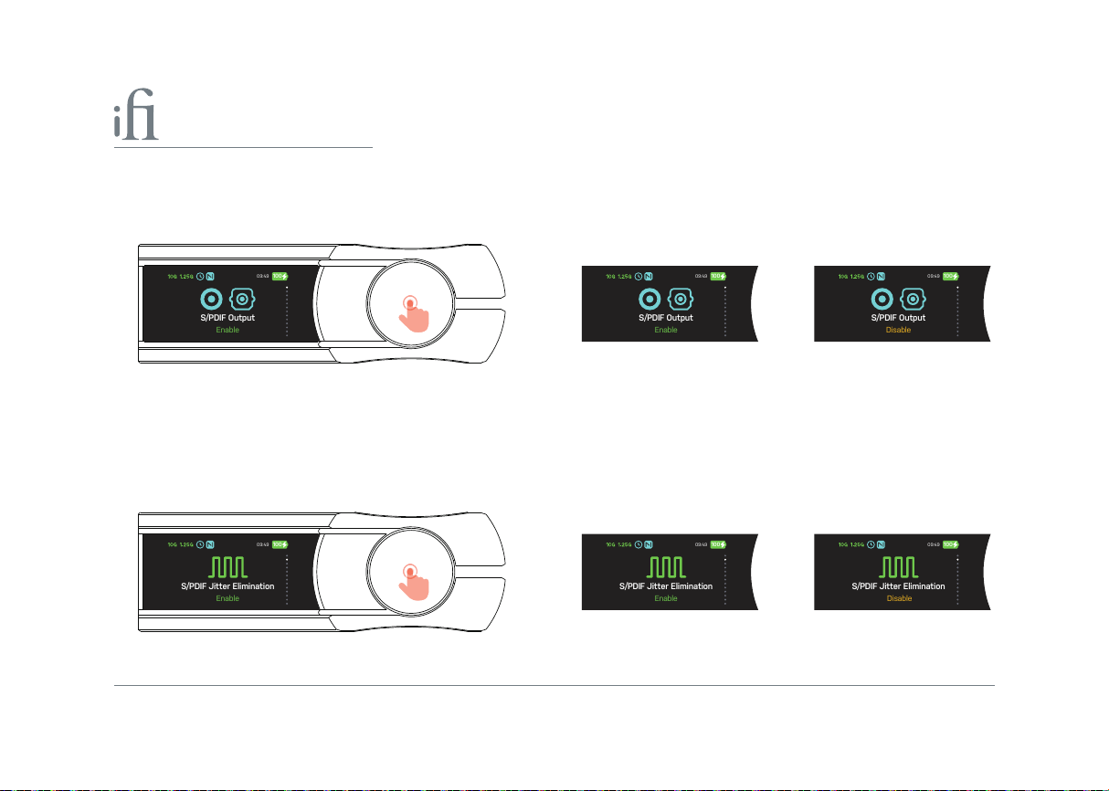
I) S/PDIF Output
09:49
10
0
S/PDIF Output
Enable
09:49
10
0
S/PDIF Output
Enable
09:49
10
0
S/PDIF Output
Disable
09:49
10
0
S/PDIF Jitter Elimination
Enable
09:49
10
0
S/PDIF Jitter Elimination
Enable
09:49
10
0
S/PDIF Jitter Elimination
Disable
This setting Enables or Disableds S/PDIF output functionality. The default setting is 'Enabled'.
When set to 'Disabled', the S/PDIF port (12) (13) (14) Disables digital signal output.
Short Press Enabled Disabled
II) S/PDIF Jitter Elimination
This setting Enableds or Disableds S/PDIF Jitter Elimination functionality. The default setting is 'Enabled'.
When set to 'Disabled', the input digital signal remains unchanged - without Jitter Elimination or enhanced decoding. This
may cause issues with high-sampling-rate audio les, preventing them from opening or causing noise during playback.
Short press Enabled Disabled
10
Page 13
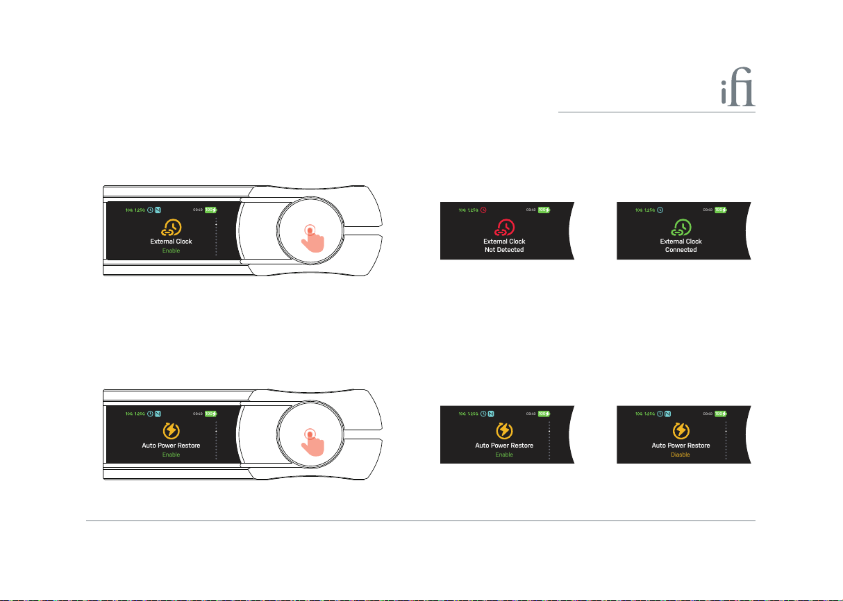
III) External Clock
09:49
10
0
External Clock
Enable
09:49
10
0
External Clock
Not Detected
09:49
10
0
External Clock
Connected
09:49
10
0
Auto Pow
er Restore
Enable
09:49
10
0
Auto Pow
er Restore
Enable
09:49
10
0
Auto Pow
er Restore
Diasble
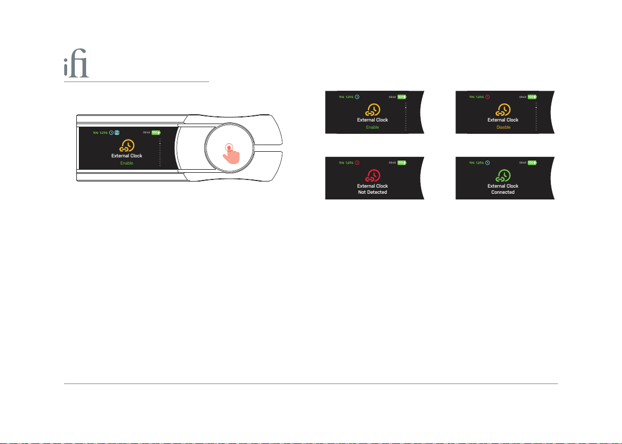
This setting Enables or Disableds External Clock (11) functionality. The default setting is 'Disabled'.
To use an external clock input, set this to 'Enable'. For more information on external clocking, refer to section (11).
Short press
Enabled Disabled
IV) Auto Power Restore
This setting Enables or Disableds Auto Power Restore functionality. The default setting is 'Disabled'.
When set to 'Enabled', the OMNI USB will automatically turn on and resume its previous state when reconnected to DC
power (9) after the battery has drained or following a power interruption.
Short press Enabled Diasbled
11
Page 14
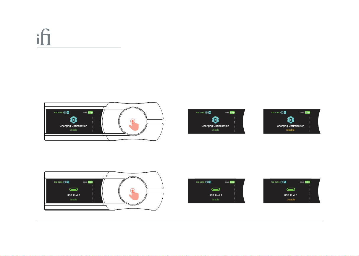
V) Charging Optimisation
09:49
10
0
Charging O
p
timisation
Enable
09:49
10
0
Charging O
p
timisation
Enable
09:49
10
0
Charging O
p
timisation
Disable
09:49
10
0
USB Port 1
Enable
09:49
10
0
USB Port 1
Enable
09:49
10
0
USB Port 1
Disable
This setting Enables or Disables Charging Optimisation functionality. The default setting is 'Disables'.d
When set to 'Enable', the Charging Optimisation function balances the battery pack's charging voltage, reducing
overcharging and over-discharging.
This helps extend battery life and improve charging eciency through precise management and intelligent equalisation
technology. It also controls temperature and voltage during charging to prevent lithium decomposition and excessive
heat, ensuring safety.
Short Press Enabled Disabled
VI) USB Port 1
This setting Enables or Disableds USB Port 1 (8). The default setting is 'Enabled'.
Short Press Enabled Disabled
12
Page 15
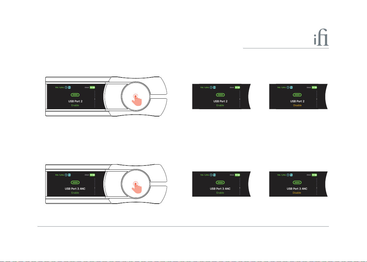
VII) USB Port 2
09:49
10
0
USB Port 3 ANC
Enable
09:49
10
0
USB Port 3 ANC
Enable
09:49
10
0
USB Port 3 ANC
Disable
09:49
10
0
USB Port 2
Enable
09:49
10
0
USB Port 2
Enable
09:49
10
0
USB Port 2
Disable
This setting Enables or Disableds USB Port 2 (17). The default setting is 'Enabled'.
Short press Enabled Disabled
VIII) USB Port 3 ANC
This setting Enables or Disableds USB Port 3 ANC (19). The default setting is 'Enabled'.
Short press Enabled Disabled
13
Page 16
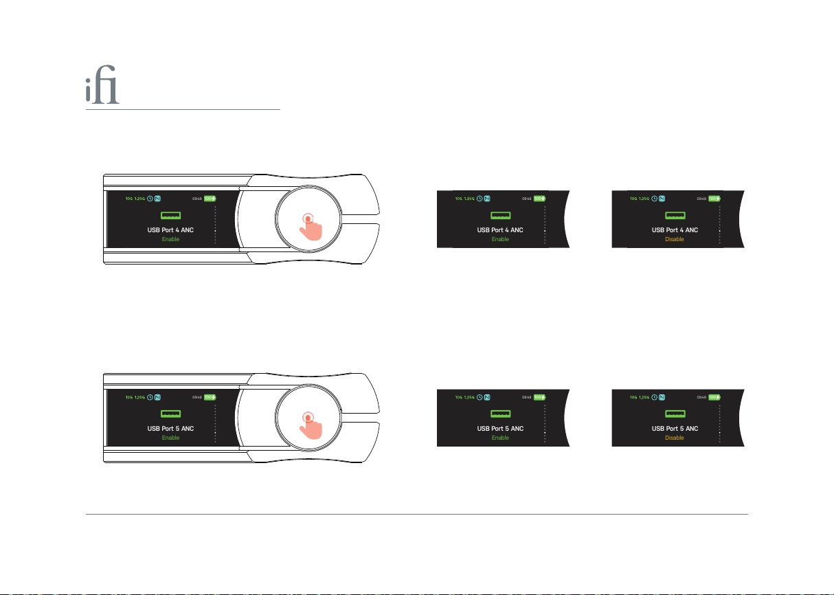
IX) USB Port 4 ANC
09:49
10
0
USB Port 4 ANC
Enable
09:49
10
0
USB Port 4 ANC
Enable
09:49
10
0
USB Port 4 ANC
Disable
09:49
10
0
USB Port 5 ANC
Enable
09:49
10
0
USB Port 5 ANC
Enable
09:49
10
0
USB Port 5 ANC
Disable
This setting Enables or Disableds USB Port 4 ANC (20). The default setting is 'Enabled'.
EnabledShort press Disabled
X) USB Port 5 ANC
This setting Enables or Disableds USB Port 5 ANC (21). The default setting is 'Enabled'.
Short press Enabled Disabled
14
Page 17
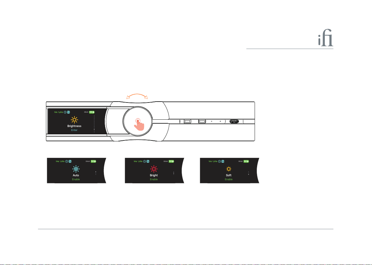
XI) Brightness
09:49
10
0
Brightness
Enter
09:49
10
0
Auto
Enable
09:49
10
0
Bright
Enable
09:49
10
0
Soft
Enable
This setting controls the TFT display screen brightness. The default setting is 'Bright'.
Short press the dial to enter brightness mode selection, turn the dial to choose a setting, then short press to conrm.
Turn
Short press
Bright The display brightness always remains bright.
Soft The display brightness always remains soft.
Auto Turns o the display after 10 seconds of no activity.
15
Page 18
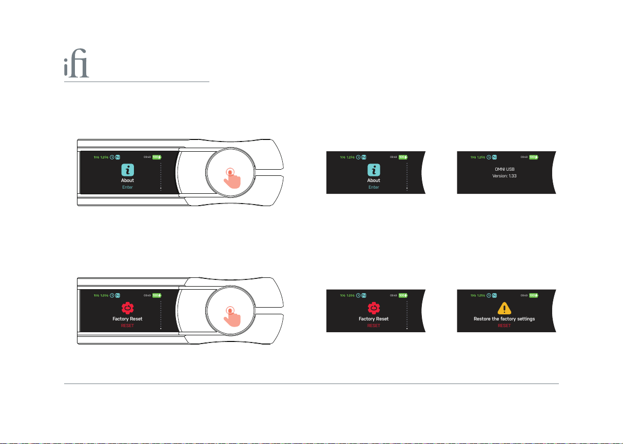
XII) About
09:49
10
0
About
Enter
09:49
10
0
About
Enter
09:49
10
0
OMNI USB
V
ersion: 1.33
09:49
10
0
Fac
tory Reset
RESET
09:49
10
0
Fac
tory Reset
RESET
09:49
10
0
Restore the fa
c
tory settings
RESET
View the device name and the current rmware version number (pictures are for illustration only, subject to the actual
version of the device).
Short press Enter Version
XIII) Factory Reset
Short press to conrm your selection. A prompt will appear on the screen to reset, and the device will restart once the
operation is complete.
Short press Enter RESET
WARNING: A factory reset will restore the menu setup options to default mode.
16
Page 19
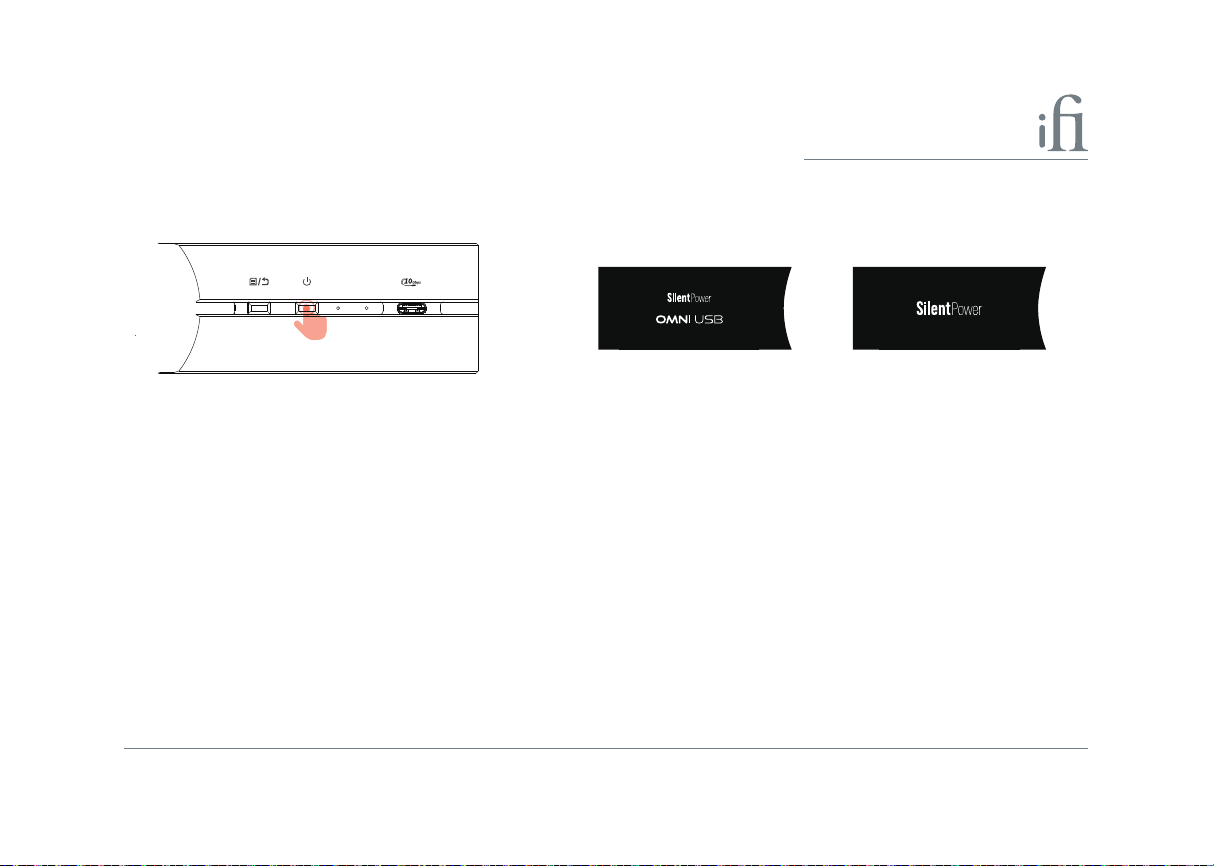
5. Power On/O
Long press ≥2s to switch the OMNI USB on/o.
Long press ≥2s On O
6. SFP 1.25G Optical bre module connection LED
The LED indicates the current status of the OMNI USB's SFP 1.25G optical connection.
LED Status Display iCons
On Connected 1.25G
O Unconnected 1.25G
7. SFP 10G Optical bre module connection LED
The LED indicates the current status of the OMNI USB's SFP 10G optical connection.
LED Status Display iCons
On Connected 10G
O Unconnected 10G
17
Page 20

STANDARD USB PORT SECTION (8) (17)
Each USB port supports input and output bi-directional transmission, and can be connected to USB devices. It supports
USB2.0 and USB3.2. It is recommended to use the standard USB ports as input ports.
8. STANDARD USB-C Port
The standard USB-C ports support input and output bi-directional transmission, can be connected to USB devices, and
support USB2.0 and USB3.2.
a) Output - Connect to USB DAC (Data & Power)
b) Input - Connect to HDD, USB DISK etc.
9. DC power supply and battery charge input port and LED for Battery Status
I) DC power supply input
DC 9V/6A, 12V/5A, 15V/4A* power input. Please connect OMNI USB to the enclosed power supply.
*A power supply unit must be able to deliver minimum rated repetitive current.
WARNING: Please use the standard powe r supply device. Using a non-standard power su pply may prevent the device from functioning properly.
II) Battery charge input
When the OMNI USB is connected to DC power, it will draw power from the DC supply instead of the battery. The battery
will fully charge in approximately 3 hours using the supplied DC power adapter.
Tip: We recommend charging the OMNI USB when it is switched o. Once fully charged, switch to battery p ower by unplugging the DC power supply, as this will
enable the full electrical isolation feature to be utilised to its full extent!
When the OMNI USB is in normal use or charging, the sur face of the casing may become warm; this is normal and nothing to worry about.
18
Page 21

III) LED for Battery Status
When the OMNI USB detects DC power or a change in battery status, the battery icon in the top right shows the updated
time or status with the matching colour.
LED Status
Red 0%-20%
Orange 21%- 49%
Green 50%-100%
Tip: When the OMNI USB detects a DC power supply, the Power LED will change colour and ash to indicate the various charging states.
10. Factory Reset
This button restores factory settings if the product encounters an error.
Long press >3s to perform a factory reset. A "Resetting" message will appear on the screen, and the device will reboot once the
reset is complete.
WARNING: Do not power o the OMNI USB during a factory reset. Loss of power during this period may damage your device and leave it unusable.
11. External Clock input port
Enabled/Disabled External Clock (11) function, default ‘Disabled’.
If you need to use an external clock input, please set to ‘Enabled’. For external clock, please see (11).
With ‘External Clock’ set to ‘Enabled’, the OMNI USB will automatically detect the external clock input signal.
If no input 10 MHz clock signal is detected or the external clock signal is not recognised, the OMNI USB will automatically switch
back to the internal clock, and the clock icon in the top left of the display will turn red.
A sine or square wave signal may be used, 1Vpp nominal, 75Ω.
19
Page 22
09:49
10
0
External Clock
Enable
09:49
10
0
External Clock
Enable
09:49
10
0
External Clock
Diasble
09:49
10
0
External Clock
Not Detected
09:49
10
0
External Clock
Connected
Enabled Diasbled
Short press
Connected Unconnected
12. S/PDIF Optical output port
This is the S/PDIF TOSLINK Optical signal output. Connect it to the Optical input port of a digital device.
13. STANDARD S/PDIF Coaxial output port
This is the standard S/PDIF Coaxial signal output (Output level 1-2V). Connect it to the coaxial input port of a digital device.
14. ENHANCED S/PDIF Coaxial output port
This is the standard S/PDIF Coaxial signal output (Output level 1-2V). Connect it to the coaxial input port of a digital
device.
Tip: (12) (13) (14) S/PDIF standard supports PCM sample rates up to 192kHz.
20
ON
Page 23

15. SFP 10G Optical bre input port
This is the SFP 10G optical input port. Please plug the supplied OMNI USB 10G bre optical module into this port.
16. SFP 1.25G Optical Fibre input port
This is the SFP 1.25G optical input port. Please plug the supplied OMNI USB 1.25G bre optical module into this port.
Tip: The OMNI USB 10G and 1.25G SFP bre optic modules are factory-tted to the OMNI USB bre optic module port.
Tip: Please use the supplied dedicated optical bre cable to connect the 10G and 1.25G SFP Optical Fibre Output Port of the USB OptiLink with the 10G and
1.25G SFP Optical Fibre Input Port of the OMNI USB.
17. STANDARD USB-C Port
The standard USB-C port support input and output bi-directional transmission, can be connected to USB devices, and
support USB2.0 and USB3.2.
a) Output - Connect to USB DAC (Data & Power)
b) Input - Connect to HDD, USB DISK etc.
18. Grounding Terminal
This is the ground terminal for the OMNI USB. Use an earth wire to connect it to any grounded object or device
capable of being earthed.
21
Page 24

PUREPORT USB PORT SECTION (19) (20) (21)
Each USB port supports bi-directional transmission for both input and output, and can be connected to USB devices that
support USB2.0 and USB3.2. As the ultra-pure ports feature Active Noise Cancellation III (ANC3) technology, it is
recommended to use them as output ports.
19. PUREPORT USB-C Data and Power output port
The Pure Port USB-C port supports bi-directional input and output transmission. It is compatible with USB devices and
supports both USB 2.0 and USB 3.2 standards.
a) Output - Connect to USB DAC (Data & Power)
b) Input - Connect to HDD, USB DISK etc.
20. PUREPORT 2 x USB-A Power output port
The 'Pure Port' USB-A Power ports only output power, and can provide power to USB devices.
21. PUREPORT USB-A Data and Power output port
The 'Pure Port' USB-A ports support bi-directional input and output transmission. It is compatible with USB devices and
supports both USB 2.0 and USB 3.2 standards.
a) Output - Connect to USB DAC (Data & Power)
b) Input - Connect to HDD, USB DISK etc.
22
Page 25
“iFi Nexis”
Download the Nexis app for added features and future updates
Set up your OMNI USB using our iFi Nexis App
Please search for "OMNI USB" within the iFi Nexis app.
The iFi Nexis app gives you access to all OMNI USB features and settings, including OTA upgrades, network status
monitoring*, and more**.
*OTA (Over-the-Air) technology enables automatic rmware updates via the network.
**You can easily and conveniently view the status of all OMNI USB network ports.
23
Page 26

Scan the QR code to view the ocial iFi audio OMNI iDSD 2 video on YouTube.
Cautions
1. Avoid extreme heat, cold and humidity.
1
2. Avoid dropping or crushing the OMNI USB.
Prolonged Heat Exposure
Your OMNI USB may become very warm during normal use. It is important to keep it on a hard, stable, and
2
well-ventilated work surface when in use.
24
Page 27
Quick Start Guide
Enter/Exit Menu Settings
TFT Display
Multi-Function Dial
Enhanced S/PDIF
Coaxial Output Port
Standard S/PDIF
Coaxial Output Port
DC Power Supply
and Power Indicator
Factory Reset
Clock Sync Input
S/PDIF Optical Output Port
SFP 10G Optical Fibre
Module Input Port
SFP 1.25G Optical Fibre
Module Input Port
Ground Terminal
10G Fibre Connection LED
Standard USB-C Data/Power Port
1.25G Fibre Connection LED
PurePort 2 X USB-A
Power Output Ports
PurePort 2 X USB-A
Data/Power Output Ports
PurePort USB-C
Data/Power
Output Port
Standard USB-C
Data/Power Port
SFP 1.25G Optical Fibre Connection Status LED
Power Connection Status
SFP 10G Optical Fibre Connection Status LED
LED Brightness Adjustment Button
SFP 1.25G Optical Fibre Output Port
USB-C Host Input Port
USB-C PD3.0 Fast Power Input SFP 10G Optical Fibre Output Port
25
Page 28
1
Power (OMNI USB)
DC Power Supply and Power Indicator
4
Input (OMNI USB)
Clock Input
10G Optical Fibre Module Input Port
1.25G Optical Fibre Module Input Port
2
Input (OPTILINK)
USB-C Host Port
3
Output (OPTILINK)
26
USB-C PD3.0 Fast Power Input
LC Fibre Cable
SFP 1.25G Optical Fibre Output Port
SFP 10G Optical Fibre Output Port
5
Output (OMNI USB)
PurePort 2 X USB-A Power Output Ports
PurePort 2 X USB-A Data/Power Output Ports
Optical Output Port
Standard USB-C Data/Power Port
PurePort USB-C Data/Power Output Port
Enhanced Coaxial Output Port
Standard Coaxial Output Port
Page 29
6
TFT Display Screen (OMNI USB)
11223
115mW
USB 1
USB 3
--
ANC
6
USB 5
--
ANC
7
TFT Menu (Rotate for Menu)
8
Brightness
Power ON/OFF - Screen Brightness
USB 2
USB 4
ANC
DSD
445
09:49 100
205mW
2.5W
256
Module Connection Status
External Clock
Nexis App Connection
3
Remaining Battery Life
Battery Status
5
Signal Inputs
6
27
Page 30

SPECIFICATIONS
Inputs:
Optical 1 x SFP 10G Optical Fibre
1 x SFP 1.25G Optical Fibre
Clock Sync 1 x 10MHz BNC External Clock
Outputs:
Standard 1 x S/PDIF Optical/TOSLINK (PCM up to 192kHz, 24-bit)
1 x S/PDIF Coaxial (PCM up to 192kHz, 24-bit)
Enhanced 1 x S/PDIF Coaxial (PCM up to 192kHz, 24-bit)
USB port:
Standard (Input) 2 x USB-C (Front & Back)
Pure (Output) 2 x USB-A (Power & Data)
1 x USB-C (Power & Data)
Pure Power (Output) 2 x USB-A (Power Only)
USB compliancy: USB 3.2 (USB 2.0 compatible)
Data speeds: 10Gbps/5Gbps/480Mbps/12Mbps/1.5Mbps
28
Page 31

General
Power supply requirement: DC 9V/6A, 12V/5A, 15V/4A* (centre pin +ve)
Power consumption: <2W idle, 50W max.
Battery: Lithium-Polymer 8,000mAh
Battery life: 10-15 hours
Grounding terminal: Binding post
Dimensions: 214 x 158 x 41 mm (8.4" x 6.2" x 1.6")
Net weight: 1.25kg (2.76lbs) with SFP optical module installed
Limited Warranty: 12 months*
*A power supply unit must be able to deliver minimum rated repetitive current
See FAQ at silentpower.tech for more information
12 months typical or as permitted/required by local reseller laws.
Specications are subject to change without notice.
29
Page 32

SPECIFICATIONS
USB port:
Power & Data input: 1 x Host USB-C
Power input: 1 x PD3.0 USB-C
Power output: 1 x PD3.0 USB-C (via Host USB-C)
Optical outputs: 1 x SFP 10G Optical Fibre
1 x SFP 1.25G Optical Fibre
USB compliancy: USB 3.2 (USB 2.0 compatible)
Data speeds: 10Gbps/5Gbps/480Mbps/12Mbps/1.5Mbps
USB-C PD3.0 Power support: 100W (20V/5A)
30
Page 33

General
Power supply requirement: DC 5V/2A*
Power consumption: ~3W max.
Dimensions: 99 x 92.8 x 24.2mm (3.9 x 3.7 x 1")
Net weight: 268g (0.59lbs) with SFP optical module installed
Limited Warranty: 12 months*
*A power supply unit must be able to deliver minimum rated repetitive current
See FAQ at silentpower.tech for more information
12 months typical or as permitted/required by local reseller laws.
Specications are subject to change without notice.
31
Page 34

32
Page 35

Page 36

 Loading...