

Usermanual Motors 902x_903x Page 1
Motor Silent Gliss 9020, 9021, 9022, 9023
Motor Silent Gliss 9030, 9031, 9032, 9033
User Manual March 2008

Page 2
Usermanual Motors 902x_903x
Copyright April 2007 by Silent Gliss International Ltd., 3073 Gümligen/Berne (Switzerland)
Realised by Silent Gliss International, Group Headquarters
Printed in Switzerland

Usermanual Motors 902x_903x Page 3
1
2
3
4
5
6
7
8
9
10
4
4
5
5
6
11
17
18
20
20
Introduction and Product Overview
Intended Application
Safety Instructions
Technical Specications
Connection and Operating Equipment
Programming and operating of SG 9020/9021
and SG 9030/9031 motors
Programming and operating of SG 9022/9023
and SG 9032/9033
Group Control
Troubleshooting
Declaration of Conformity
Table of Contents
Please read chapters „Intended application“ and „Safety Instructions“
before installing or connecting. Non-observance as well as opening
and manipulation of the motor will result in voiding of the Silent Gliss
liability and warranty.

Page 4
Usermanual Motors 902x_903x
1 Introduction and Product Overview
This User Manual describes the setting up and programming of the
different motor types, which are used in connection with the Silent
Gliss Electrical Curtain Track System SG 5400 and SG 5420 as well as
with the Radio Remote Control System SG 9940. Please refer to the
separate tting instructions and wiring diagrams for the installation of
the Systems SG 5400 and 5420.
This User Manual applies to following Silent Gliss motor variations:
2 Intended Application
The motors mentioned in Chapter 1 may only be used in combination
with the designated Silent Gliss Systems.
The motor is solely designed for indoor use. Application in wet areas
like bathrooms, indoor swimming-pools, saunas etc. is not permitted.
Please note that Radio Control Systems are not permitted in certain
locations such as Hospitals and Airports.
Please ensure that other equipment is not being controlled by radio
equipment using the same frequency.
9020
9021
9021
9022
9023
SG Nr.
9023
9030
9031
9031
9032
9033
9033
ERP Nr.
100902000
100902101
100902102
100902200
100902301
100902302
100903000
100903101
100903102
100903200
100903301
100903302
Long description
Motor 90-250V AC*
Motor 90-250V AC*,radio 868MHz
Motor 90-250V AC*,radio 915MHz
Motor 90-250V AC*,manual override
Motor 90-250V AC*,radio 868MHz, manual override
Motor 90-250V AC*,radio 915MHz, manual override
Motor 24V DC
Motor 24V DC, radio 868MHz
Motor 24V DC, radio 915MHz
Motor 24V DC, manual override
Motor 24V DC, radio 868MHz, manual override
Motor
*260V AC CB
24V DC, radio 915MHz, manual override
Short description
on motor
9020.000.00
9021.868.00
9021.915.00
9022.000.MO
9023.868.MO
9023.915.MO
9030.000.00
9031.868.00
9031.915.00
9032.000.MO
9033.868.MO
9033.915.MO

Usermanual Motors 902x_903x Page 5
3 Safety Instructions
The Motor may be used only in dry rooms.
The Motor may not be used in explosive areas.
The Motor is not intended for use by young childrens or inrm
persons without supervision.
Only original Silent Gliss parts may be used.
The installation, inspection and troubleshooting of the drive mecha-
nism may only be performed by qualied specialists. Please consider
the country specic regulations in regards of connection of the motors
to the mains.
The proper operation of the motor in combination with the Electric
Curtain Track Systems is only guaranteed with professional installati-
on, xing, as well as sufcient electric power supply.
Cleaning of the motor may only be performed if the motor is discon-
nected from the mains voltage.
The motor must not be used if cables, plugs, or the motor are
damaged.
Please ensure the specication detailed below and in the declaration
of conformity (page 20) conform with the necessary regulations in the
intended country of use and the radio frequency is approved for that
country.
4 Technical Specications
Technical data for motors only. For the technical data for the entire
curtain track system refer to the corresponding Assembling- / Fitting
Instruction.
9020-9023 9030-9033
Voltage Supply
Frequency
Current
Frequency of radio control
(only for 9021/9023/9031/9033)
90 - 250V AC**
50 - 6 0 Hz
0.5 - 1 A
868 or 915 MHz*
24 V DC
--
2.5 A
868 or 915 MHz*
Speed
Noise level
Dimension
Max. drapery weight
Weight
110 rpm
< 45 dBA (30cm)
240 x 90 x 60mm
1kg
110 rpm
< 45 dBA (30cm)
240 x 90 x 60mm
1kg
44kg / 97lbs 44kg / 97lbs

Page 6
Usermanual Motors 902x_903x
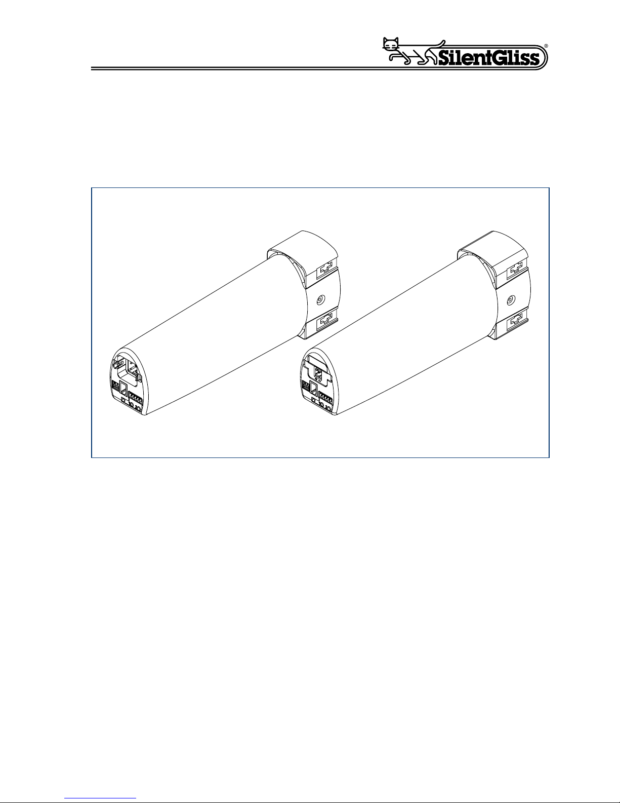
5 Connection and Operating Equipment
5.1 Overview
The Motor is available in two power supply options; 90 – 250V
AC/260V AC CB as well as 24V DC. The power plugs are designed
differently and cannot be mixed up. The remaining ports and indicators
are identical on both motors.
The following main overview of the ports and indicators may be used
for both motors. The subsequent chapters deal in detail with the functions, allocations and setting of the ports and indicators.
9020-9023 9030-9033
Voltage Supply
Frequency
Current
Frequency of radio control
(only for 9021/9023/9031/9033)
90 - 250V AC**
50 - 6 0 Hz
0.5 - 1 A
868 or 915 MHz*
24 V DC
--
2.5 A
868 or 915 MHz*
Speed
Noise level
Dimension
Max. drapery weight
Weight
110 rpm
< 45 dBA (30cm)
240 x 90 x 60mm
1kg
110 rpm
< 45 dBA (30cm)
240 x 90 x 60mm
1kg
44kg / 97lbs 44kg / 97lbs
Temperature ranges:
For operation
Storage
Safety class
*(depending
**260V AC CB
on regulation of respective country)
0 C to + 60 C
-20 C to + 70 C
IP40
0 C to + 60 C
-20 C to + 70 C
IP40
2 1
2 1
Programming Buttons
Power Plug
LED
Low Voltage Switch
Connections
DIP Switch
Special Function Socket
SG 9020 - 9023
(90-250V AC/
260V AC CB)
SG 9030 - 9033
(24V DC)

Usermanual Motors 902x_903x Page 7
5.2 Special Function Socket
Used in connection with the Manual Override version for the motors
SG 9022 / 9023 / 9032 / 9033.
5.3 Low Voltage Switch Connections
Used for control by low voltage, group control or for the connection
of the programming cable.
5.4 Programming Buttons
Used for the programming of the endstops as well as for the
intermediate positions (scenes).
The numbers of the buttons are marked on housing of the motors.
The right button is nr. 1, the left nr. 2.
DenotationPin
1
2
3
4
GND
Endstop 1
Endstop 2
VCC
123
4
DenotationPin
1
2
3
4
5
Common
Open - Single
Close - Single
Open - Group
Close - Group
5
4
3
2
1
Programming
buttons

Page 8
Usermanual Motors 902x_903x
5.5 LED
Flashes or is illuminated in the programming mode.
5.6 Mains Connection and Wiring of
SG 9020 – 9023 (90 – 250V AC/260V AC CB)
Wiring: The motors SG 9020 – 9023 can be wired for non permanent
power as well as for permanent power. The wiring is to be employed as
required by local codes. The wiring diagrams are as follows:
Note!
The earth wire has to be wired according to the international wiring
standards for buildings by reason of a proper grounding. The used
switch must be equiped with a neutral terminal.
LED
DenotationPin
1
2
3
4
Neutral
Phase (rotating direction left)
Phase (rotating direction right)
PE,
Parallel jacketed
thermoplastic cable,
300V with third
conductor for
grounding. (PVC)
Minimum lenght 72.04" (1.83m)
1
Contact H-A 3TGV 10426400
Contact H-A 3BS 10421000
2
3
1
2
3
Phase
Neutra
l
1
2
3
Phase
Neutra
l
Low Voltage switched
(requires permanent mains supply)
Mains Switched (90-260VAC)

Usermanual Motors 902x_903x Page 9
5.7 Mains Connection and Wiring of
SG 9030 - 9033 (24V DC)
Wiring: The motors SG 9030 - 9033 are always connected with permanent power.
5.8 DIP - Switch Settings of SG 9020 - 9023
(90 - 250V AC/260V AC CB)
and SG 9030 - 9033 (24V DC)
The DIP Switches are used to set the motor depending on the wiring
and the required operation mode. Following table shows the
possibilities.
+
-
ON
1 2 3
ON
1 2 3
DIP Switch Position
"off-off-off"
DIP Switch Position
"on-on-on"

Page 10
Usermanual Motors 902x_903x
ON
1 2 3
Controlled by switched mains
Non Latching Switch: the motor will latch immediately it receives a
momentary signal and continue to the pre set end position.
To stop the motor while it is running apply a short signal in the
opposite direction.
For vertical Blinds only. Use a non latching switch. Short pulses
will rotate the angle of the blind but if the switch is held depressed
for more than 1 second the motor will latch and the blind will run to
the fully open or fully closed position.
Non latching switch: The motor will only run when the signal is
present (switch depressed). Mainly used when the motor is
being controlled from an AV or BMS controller.
As on-off-off but with the manual/electrical option enabled for
use with a 5420 system.
As off-on-off but with the manual/electrical option enabled for
use with a 5420 system.
As on-on-off but with the manual/electrical option enabled for
use with a 5420 system.
Not applicable
off-off-off
on-on-off
off-off-on
on-off-on
off-on-on
on-on-on
Operational Mode
DIP Switch
Position
Controlled by low voltage switching
(requires permanent mains supply)
or Radio
on-off-off
off-on-off
Important:
When changing the DIP-mode please allways plug-off the motor rst!

Usermanual Motors 902x_903x Page 11
6 Programming and Operating of
SG 9020/9021 and SG 9030/9031
Motors
6.1 Main Overview
After installation of a motor onto the designated Curtain Track System,
the end stops – and if required, the intermediate positions can be
programmed. This programming can be carried out in several ways:
by means of the programming buttons on the motor, by means of the
optional available Programming Cable SG 5651 or by means of the
Radio Remote Control System SG 9940.
6.2 Programming by means of Programming Buttons
on Motor or Programming Cable SG 5651
The following table shows the different steps required to program
the nal stops regardless of mains or low voltage switch type. If the
Programming Cable SG 5651 is used to program the end stops, it
is required to plug it into the Low Voltage Switch connection before
programming.
To do Signal
Step
12Check if the DIP switch setting is correct
(Setting according to Chapter 5.8).
Disconnect power supply of the motor for 5
seconds and make sure that the motor will
have permanent power supply when
reconnected. Typically unplug power
lead from motor.

Page 12
Usermanual Motors 902x_903x
6.3 Programming by means of Radio Remote
Control SG 9940
The remote control has to be teached-in with the motor before
the programming of the end positions by means of the Radio Remote Control System can be performed. This can be carried out
with the following steps. Please refer to the user manual which is
enclosed with every delivered remote control.
To do Signal
Step
1
2
3
4
5
6
Check if the DIP switch setting is correct
(Setting according to Chapter 5.8).
Disconnect power supply of the motor for 5
seconds and make sure that the motor will
have permanent power supply when
reconnected. Typically unplug power
lead from motor.
Reconnect to power supply and
simultaneously push programming
button 1 or 2.
Simultaneously press both buttons (1&2)
and hold depressed for > 6 seconds.
After 3 seconds motor will sound and the
light will flash. Do not release the buttons.
Wait until motor sounds and light flashes
for the second time. Motor is then in programming mode for 3 minutes.
Use programming button 1 to drive the
system to the first end stop position.
Then press both buttons simultaneously
for 3 seconds. This end position is
then stored.
Use programming button 2 to drive the
system to the other end stop position.
Then press both buttons simultaneously
for 3 seconds. This end position is
then stored.
Acoustic Signal,
LED blinks
Acoustic Signal
and LED blinks
after 3 and 6 seconds
respectively
Acoustic Signal
and LED blinks 1 x
Acoustic Signal
and LED blinks 1 x
Step
Todo Signal
1 Check if the DIP switch setting is correct
(Setting according to Chapter 5.8).

Usermanual Motors 902x_903x Page 13
To do Signal
Step
1
2
3
4
Check if the DIP switch setting is correct
(Setting according to Chapter 5.8)
Disconnect power supply of the motor for
5 seconds and make sure that the motor
will have permanent power supply
Establish power supply and simultaneously
push programming button 1 or 2 on Motor.
Select the desired chanel by pressing the
select button (only SG 9942)
Acoustic Signal,
LED lights
Chanel LED on transmitter lights on
2 Disconnect power supply of the motor for
5 seconds and make sure that the motor
will have permanent power supply when
reconnected. Typically unplug power lead
from motor.
3 Move the curtain with button 1 or 2 on the
motor about to the middle position of the
two endstops.
4 Select the desired chanel by pressing the
select button (only SG 9942)
Chanel LED on
trans-mitter lights on
5 Position yourself in front of the motor
with the remote control in your hand, and
open the front cover of the device and
press button „P“.
Curtain moves
independently
approx. 2 minutes
open and close
6 To dene the allocation of the buttons
press rst button on the transmitter as
soon as the curtain begins to move in the
rst direction.
The curtain will
come to a briey
hold
7 As soon as the curtain begins to move
again, press the second button on the
handheld transmitter. The transmitter has
been succesfully programmed.
The curtain will
come to a stop
Adjusting the endpositions

Page 14
Usermanual Motors 902x_903x
6.4 Programming and Accessing of intermediate
Positions
Two intermediate positions can be set for the Electric Curtain
Track System with low voltage switching. The programming of
the intermediate positions doesn’t have to be carried out in the
programming mode. It can be carried out in operational mode.
Programming with Low Voltage Control:
To do Signal
Step
1
2
3
4
5
6
Check if the DIP switch setting is correct
(Setting according to Chapter 5.8)
Disconnect power supply of the motor for
5 seconds and make sure that the motor
will have permanent power supply
Establish power supply and simultaneously
push programming button 1 or 2 on Motor.
Select the desired chanel by pressing the
select button (only SG 9942)
Push simultaneously programming button
1 and 2, >6 seconds. The motor is now
able to be programmed for 3 minutes
Move to first end position with programming
button 1. Subsequently, push both programming buttons simultaneously for 3 seconds.
The first end position is now saved
Acoustic Signal,
LED lights
Chanel LED on trans-
mitter lights on
Acoustic Signal and
LED blinks after 3 and
6 seconds respectively
Acoustic Signal and
LED blinks 1 x
7 Move to the second end position with pro-
gramming button 2. Subsequently, push
both programming buttons simultaneously
for 3 seconds. The second end position is
now saved
Acoustic Signal and
LED blinks 1 x
To do Signal
Step
12Use button 1 to move the system to the
required scene position 1. When you reach
the required position press button 2 twice
while still holding down button 1
Use button 2 to move the system to the
required scene position 2. When you reach
the required position press button 1 twice
while still holding down button 2. The
intermediate positions are now adjusted.
Acoustic Signal and
LED blinks 1 x
Acoustic Signal and
LED blinks 1 x

Usermanual Motors 902x_903x Page 15
Programming with Remote Control:
Recalling the intermidiate positions: The curtain automatically moves to
the programmed positions by briey pressing 2 times the buttons which
are assigned to the intermediate positions.
6.5 Resetting of Motor to Factory Status
To do Signal
Step
12Press button 1 permanently and move the
curtain to the desired intermediate position
1. Arrived at the first intermediate position,
press button STOP simultaneously.
Press button 2 permanently and move the
curtain to the desired intermediate position
2. Arrived at the first intermediate position,
press button STOP simultaneously.
Acoustic Signal and
LED blinks 1 x
Acoustic Signal and
LED blinks 1 x
To do Signal
Step
12Disconnect power supply of the motor for 5
seconds and make sure that the motor will
have permanent power supply when
reconnected. Typically unplug power
lead from motor.
Reconnect to power supply and
simultaneously push programming
button 1 or 2.
Acoustic Signal,
LED blinks
3 Simultaneously press both buttons (1&2)
and hold depressed for > 6 seconds.
After 3 seconds motor will sound and the
light will flash. Do not release the buttons.
Wait until motor sounds and light flashes
for the second time.
Acoustic Signal
and LED blinks
after 3 and 6 seconds
respectively

Page 16
Usermanual Motors 902x_903x
6.6 Deleting transmitters 9940 to motors
SG 9021/9023 and SG 9031/9033
Transmitter 9941 (1-Channel)
Transmitter 9942 (5+1-Channel)
To do Signal
Step
1
2
3
Make shure that the motor has permanent
power.
Open the front cover on the device and
press the following buttons simultaneously:
- Programming button P
- STOP button
Keep these two buttons pressed until the
LED goes out briefly.
LED turns off short
1 Make shure that the motor has perma-
nent power.
2a Deleting of a specied channel
Select the channel to be deleted. Then
open the front cover and press the following buttons simultaneously:
Programming button P + STOP button
2b Keep all of these buttons pressed until
the LED ashes off short
LED ashes off
short
3a Deleting of all channels
Select all Channel. Open the front cover
and press the following buttons simul-
taneously: Programming button P + UP
button + STOP button + DOWN button
3b Keep all of these buttons pressed until
the LED ash off 3 x
LED ash off 3 x

Usermanual Motors 902x_903x Page 17
7 Programming and Operating of
SG 9022/9023 and SG 9032/9033
These motors and Electric Curtain Track Systems are equipped with
a Manual Override function, i.e. the curtain can be moved by hand if
the motor is turned off. This function is only applicable with a low voltage switching.. In addition, no intermediate position can be programmed.
The programming occurs through following steps
To do Signal
Step
1
2
3
Check if the DIP switch setting is correct
(Setting according to Chapter 5.8).
Disconnect power supply of the motor for 5
seconds and make sure that the motor will
have permanent power supply when
reconnected. Typically unplug power
lead from motor.
Pull the curtain to about the middle position
between the two end positions.
5
6
7
Reconnect to power supply and
simultaneously push programming
button 1 or 2.
Move the curtain to one end position.
Motor is programmed.
Acoustic Signal,
LED lights
Motor stops
automatically
4 Simultaneously press both buttons (1&2)
and hold depressed for > 6 seconds.
After 3 seconds motor will sound and the
light will flash. Do not release the buttons.
Wait until motor sounds and light flashes
for the second time. Motor is then in programming mode for 3 minutes.
Acoustic Signal
and LED blinks
after 3 and 6 seconds
respectively

Page 18
Usermanual Motors 902x_903x
8 Group Control of Motors
8.1 Group Control via Mains
Motors can be connected in parallel when mains switching. 3 motors
maximum are recommended. If quantities above 3 motors in parallel
are required, a qualied electrician must be consulted to ensure that
the supply, wiring and switching is suitable for the electrical load.
For motors to all run in the same direction on command attention must
be paid to ensure that the connections to all motors are identical. If
a motor is specically required to operate in the reverse direction on
command the connections to pins 2 & 3 should be reversed on that
specic motor.
2 1 2 1
Group
Switch
Phase Neutral
2 3
1
2 3
1

Usermanual Motors 902x_903x Page 19
8.2 Group Control via Low Voltage Inputs (max. 15)
If a motor is required to run in the opposite direction to others wired
within the same group connections 2 & 3 at the low voltage switch
connection should be reversed on that specic motor.
8.3 Group Control via Radio Remote Control
SG 9940
For the programming of the group control by means of the radio remote
control system SG 9940 please refer to the user manual which is enclosed in every delivered hand remote control device.
2 1 2 1
Group
switch
Phase
Single
switch
motor 2
Neutral
2 3
1
Phase NOTE: No protection
relays are required
Neutral
2 3
1
5 4 3 2 1 5 4 3 2 1
Single
switch
motor 1

Page 20
Usermanual Motors 902x_903x
9 Troubleshooting
... the motor doesn’t move?
Check if motor is correctly supplied with power according to the
wiring diagram and if the DIP switches are in the right position.
... the motor doesn’t move after saving the rst end stop?
Disconnect power supply. Start limit setting process again ensuring
that button 1 is used rst to drive the system to its rst limit position.
... the motor turns in the wrong direction with low voltage switching
(permanent power supply)
Exchange cable of Pin 2 with Pin 3 at the low voltage switch
terminal connection.
... the motor SG 9020 turns in the wrong direction with mains
switched connection?
Exchange cable of Pin 2 and 3 on mains plug.
... some motors 9020 / 9022 turn in the wrong direction when
connected for simultaneous operation using mains switching.
Check if Pin 2 and Pin 3 on each motor are connected identically.
10 Declaration of Conformity
Micro- Motor AG conrms herewith that this product complies with
the relevant harmonised regulations of the 73 / 23 / EEC + 89 / 336 /
EEC + 93 / 68 / EEC directives. The declaration of conformity can be
ordered at: info@micromotor.ch .
 Loading...