

User and tting Manual Silent Gliss 5090 Page
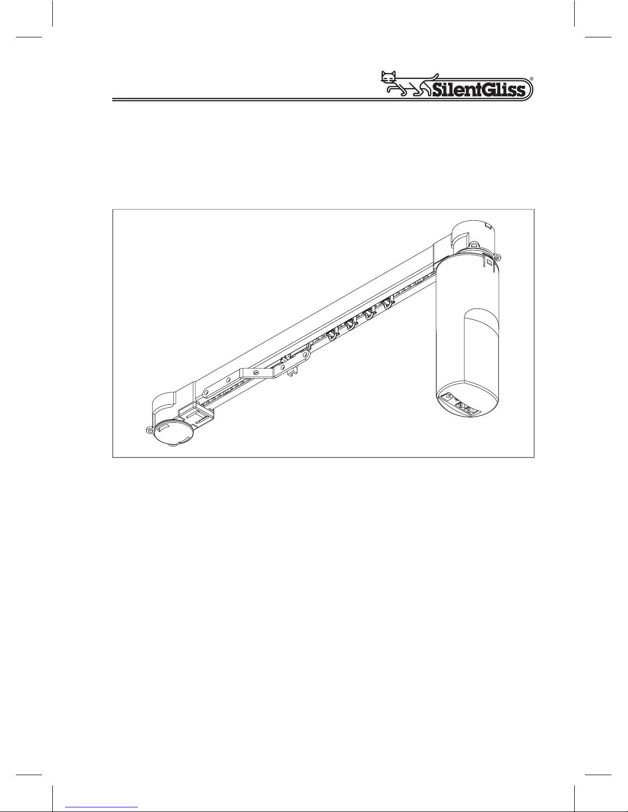
Electric Curtain Track System Silent Gliss 5090
User and Fitting Manual June 2008

Page 2
User and tting Manual Silent Gliss 5090
Copyright June 2008 by Silent Gliss International Ltd., 3073 Gümligen/Berne (Switzerland)
Realised by Silent Gliss International, Group Headquarters
Printed in Switzerland
Version

User and tting Manual Silent Gliss 5090 Page 3
2
3
4
5
6
4
9
0
4
22
23
Fitting Information
Silent Gliss 5090 Basic Operation Method:
With Switch
Option : Silent Gliss 5090IR
Option 2: Silent Gliss 5090TL
Option 3: Silent Gliss 5090TC
Problem Solver
Table of Contents
Failure to observe the following instructions may invalidate the
Silent Gliss warranty.
Important:
Before using your system Silent Gliss 5090, please read these instructions carefully and keep them safe for future reference.
A few minutes spent familiarising yourself with these components will
save you time when carrying out the installation.
Page 4
User and tting Manual Silent Gliss 5090
Fitting Information
. Deciding the best position
Points to consider when planning your installation
The system Silent Gliss 5090 may trigger some types
of burglar alarm. This may usually be remedied by
relocation of, or a change of burglar alarm sensor. If in
doubt, consult your burglar alarm supplier.
It may be easiest to have the power supply on the
same side of the window as the nearest plug socket.
You might choose to position the power supply so that
it is not visible and not touchable.
The transformer should not be placed where there is a
risk of condensation dripping onto it from a window sill
or used in damp environments such as bathrooms.
When xing avoid any hidden cabling in wall. If in doubt consult a
qualied electrician.
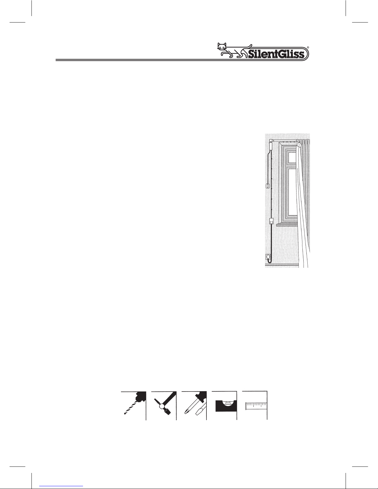
Tools for xing
Your system track is ready assembled for easy xing. Your track pack
contains everything you need to x the track to a wooden batten. If
xing directly to a wall or ceiling, appropriate xings; e.g. wall plugs will
also be needed.

User and tting Manual Silent Gliss 5090 Page 5
Bracket position
Draw a level line on the ceiling,
wall or batten at the height you
wish to position the track.
Ask your supplier about the
appropriate kind of bracket.
Note: The distance* depends on the kind of curtain used. Check that
nothing disturbs the curtain for example: radiator, window handle etc.
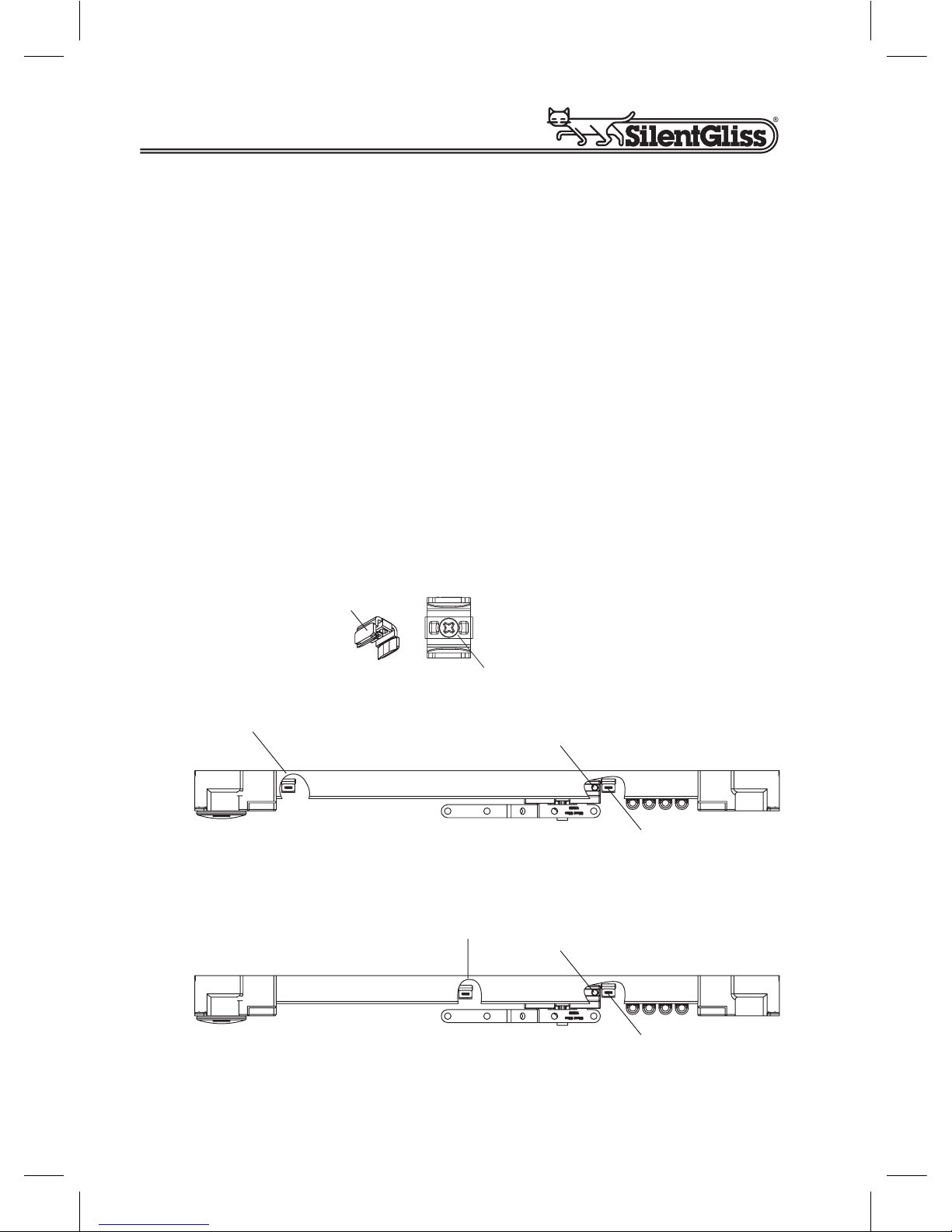
.2 Fitting the motor
Fitting the motor unit to the predetermined end of the track
Slide back locking plate () and remove. Locate motor drive shaft (2)
into pulley drive (3) inside pulley housing (5). Fully insert motor (4) into
pulley housing (5) and twist to secure motor unit onto pulley housing as
shown. Replace locking plate () to
lock the motor rmly in position.
Note: You may need to turn
motor slightly to left or right to
ensure locking plate locates
completely with a click.
To remove motor, if necessary,
reverse instructions above.
Top x with bracket 3826 Wall x with bracket 3836
10cm
30�60cm
10cm
30�60cm
5
2
4
1
3
1
80 -100
53
Page 6
User and tting Manual Silent Gliss 5090
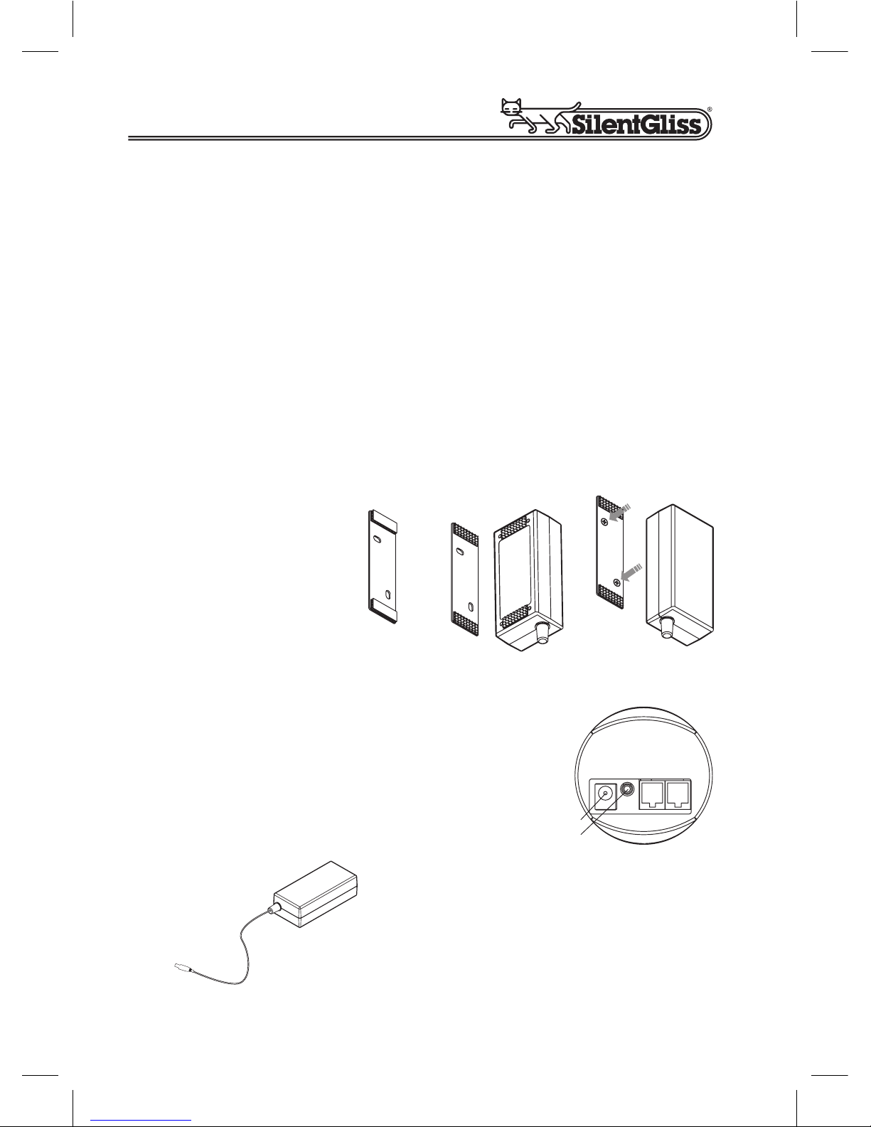
.3 Fixing the hook tape to the transformer and the
xing plate to the wall
Clean rear of transformer case, remove velcro hook strips from xing
plate (). Stick velcro hook strips in position centrally above and below
the certication sticker on the rear of the transformer case (2) lining up
with velcro loop section on the xing plate.
Position wall holder and mark through xing lugs onto the wall.
Drill xing holes using a 6mm drill, insert wall plugs provided and screw
xing plate (3) to wall.
In the event of the mains cable not reaching a convenient mains
socket, we would advise you to have an additional socket tted by a
qualied electrician.
Tidy the run of cable
between the transformer and motor unit
with the cable clips
provided. When xing
avoid any hidden
xing cabling in the
wall. If in doubt consult
a qualied electrician
1 2 3
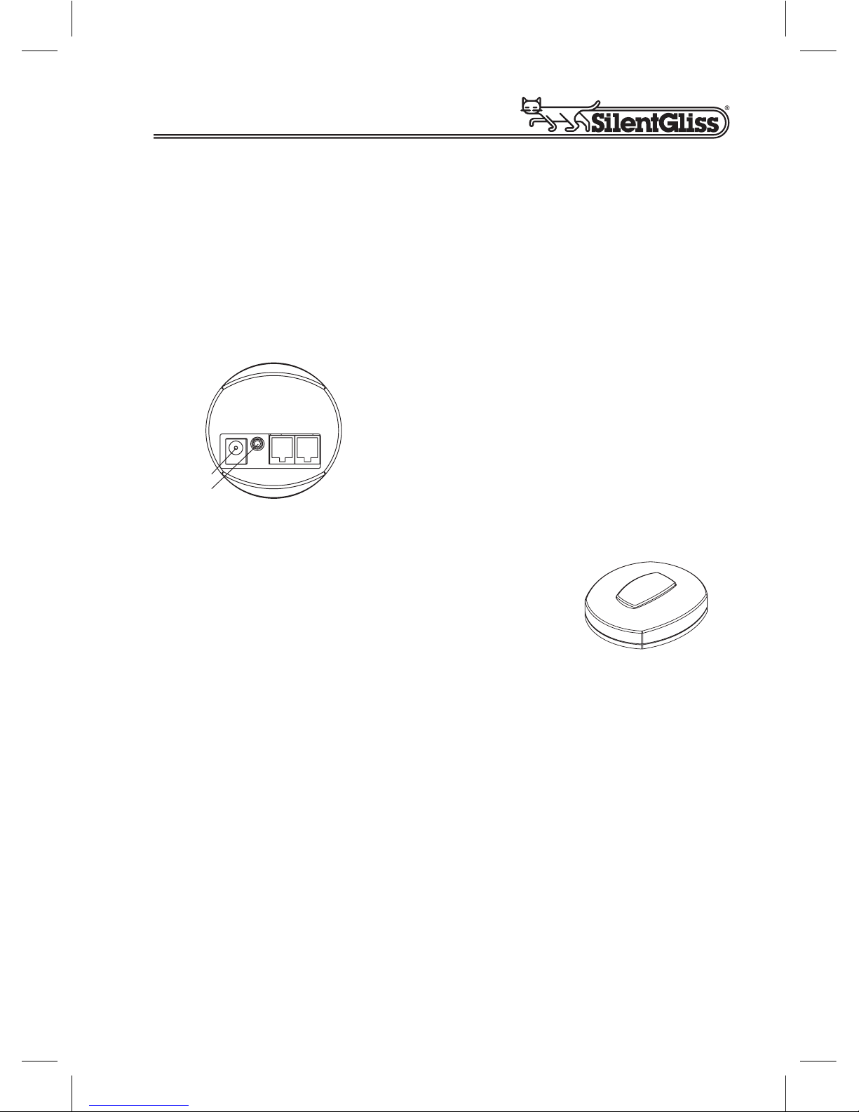
.4 Connecting the motor
Connect transformer to mains power with lead
supplied (do not switch on power at this stage).
Plug in transformer output into port () on the
bottom of the motor. Black wheel (2) is channel
for IR sensor (optional) see section 3.
Plug A is for the cable of the timer or
switch
Plug B is for the infrared sensor or
switch
A B
2
1
Motor
Transformer (with cable)
User and tting Manual Silent Gliss 5090 Page 7
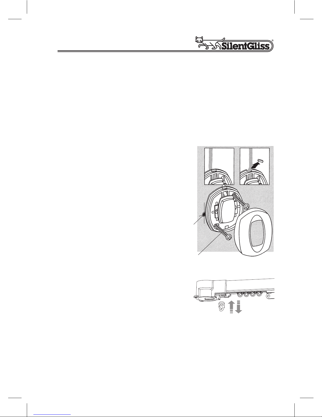
.5 Fixing the switch
Lever switch cover off switch using a at bladed screwdriver near the
cable. There are two options for tting the cable of the switch.
A. Concealed tting the switch is supplied with cable entering from
the back to allow concealment of cable.
B. Surface tting break off the blanking piece () from the
edge of the switch backplate as shown allowing the cable to t
ush to the wall.
Position the switch and mark through
holes onto the wall (2).
Drill xing holes using a 6mm drill,
insert wall plugs provided and screw
switch to wall (3). Replace cover.
Fix cable to wall with cable clips
provided.
Note: All cables are tted with
non-rewireable plugs and cannot
be shortened.
3
2
1
Switch
.6 Adding or removing gliders
Single Stack: First remove the motor
(see “Fitting the Motor” on previous
page). Insert gliders through the slot.
Pair Stack: On the opposite side of the motor, remove only the locking
plate, there will be enough space to add or remove gliders.
Note: When hanging your curtains the heading must be underslung – i. e. the top of the curtains must be completely below the
curtain track prole, failure to do so could invalidate the warranty.
Page 8
User and tting Manual Silent Gliss 5090
.7 Setting or adjusting the end stops
Having hung your curtains to the track, you can now adjust the end
stops if necessary.
If required, you can control how far the curtains draw back by means of
the end stop ().
Carefully loosen end stop (2) locking screw.
Slide the stop along the channel to the point that you want the curtains
to dress to when open or close and then fully re-tighten screw.
Re-test to the open position and re-adjust end stop ().
Note: In order to avoid damage of the system, the belt carrier (3)
must run into the end stop (1) on both sides.
3
1
Single Stack
factory set – do not move
adjustable – set to curtain fullness
2
1
3
1
Pair Stack
factory set – do not move
adjustable – set to curtain fullness
Track
User and tting Manual Silent Gliss 5090 Page 9
2 Silent Gliss 5090 Basic Operation Method:
With Switch
Connecting motor
The switch can now be plugged in to either position A or B.
Operating your curtain track with switch
Press switch » curtain moves
Press switch during moving » curtain stops
Press switch again » curtain moves back
A B
2
1
Motor
Switch

Page 0
User and tting Manual Silent Gliss 5090
3 Option : Silent Gliss 5090IR
) Motor
2) Switch
3) Infrared Sensor
4) Transformer
5) Main Plug
) Remote control
2) Wall bracket
3) Self-adhesive cover
4) Sensor unit
5) Mounting clip - sensor
6) Cable - sensor
7) Plug B - sensor
8) Cable clips
1
3
2
4
5
4
7
5
8
1
3
6
2
Infrared Set IR SG 5093

User and tting Manual Silent Gliss 5090 Page
3. Remote control
The system can be conveniently operated
from anywhere in the room using the remote
control (Ideal for curtains that may be difcult
to reach). Visible contact between sensor
and remote control is necessary in order to
dependably operate the system.
3.2 Connecting motor and infrared sensor
Unplug motor from mains.
Plug the infrared sensor into the position B on the motor.
Additionally, the switch could also be plugged into position A on the
motor. (see Basic 5090 operation section 2)
Decide where you wish to locate the sensor (4). It can be xed to the
wall by mounting clip (5) and screw (9) or clipped to a curtain by the
mounting clip (5). The sensor should be in full view, not hidden behind
the curtain or track.
Attach the sensor (4) to the wall or
curtain and secure cable with clips (8)
provided.
Note: The mounting clip (5) can be
removed from the sensor (4) for xing
or adjusting the angle of the sensor.
5
4
8
9
IR Sensor
A B
1 sensor
2 switch
Motor

Page 2
User and tting Manual Silent Gliss 5090
3.3 Wall mounting the remote control
You may wish to mount the remote handset () to a convenient wall
near the door or close to a light switch. A wall mounting bracket (2) is
provided for this purpose.
Important: Do not attempt to x mounting bracket where there is a
possibility of hidden cables, e.g. directly above or below a light switch.
If in doubt, consult a qualied electrician.
To t mounting bracket position, level and mark holes of mounting
bracket (2). Drill two holes and insert wall plugs.
Secure mounting bracket (2) to wall with screws provided.
Attached self-adhesive cover (3) onto mounting bracket (2) to cover
screw heads.
The handset locate rest securely on this bracket but remains easily
detachable for use anywhere in you room.
1
3
2
IR Remote Control

User and tting Manual Silent Gliss 5090 Page 3
3.4 Controlling more than one track
You can use the handset to operate
one or more systems by using the
channel selector switch. There are four
positions, ,2,3 and 23(All).
The motor is preset to receive all
channels.
If you have more than one system in
the same room and you would like to
operate them independently, you will
need to set each motor to a separate
channel as follows:
Adjusting and testing the infrared system
If you have just one track and no other infrared systems in your house,
then the easiest way is to set the remote control to position 23(All).
If you have more than one system and would like to control them separately, choose remote control position and turn the black wheel ()
with small at blade screwdriver to position on the rst motor.
For the second motor, set the switch on the remote control to position 2
and turn the black wheel on the second motor to position 2.
For the third motor, set the switch on
the remote-control to position 3 and
turn the black wheel (potentiometer)
on the third motor to position 3.
3
2
1
123
3
2
1
All
A B
1
Motor
Channel
selector
switch
Side view of the
remote control

Page 4
User and tting Manual Silent Gliss 5090
4 Option 2: Silent Gliss 5090TL
4. Fixing the timer unit
The timer unit is xed to the wall by means of the xing bracket ().
When xing, avoid any hidden cabling in the wall. If in doubt, consult a
qualied electrician.
Drill 6mm holes, insert wall plugs provided and screw wall bracket to
wall.
Before mounting the timer unit onto the bracket, plug the motor cable
into position A and the light sensor into position C (see next page).
You have the possibility to hide the cable on the rear side of the timer
unit. Both cables could leave timer unit on the left or right side or one
cable to the left and the other to the right, depending on where motor
and light sensor are located.
C
A
Rear of Timer
1

User and tting Manual Silent Gliss 5090 Page 5
4.2 Connecting motor & timer
) Unplug motor from mains.
2) Plug the timer unit cable into position A on the motor ().
3) Plug in the other side of the cable into position A on the timer
unit (2).
4) Plug in the light sensor into position C on the timer
unit (3).
5) Additionally, the switch could be plugged into position B on the
motor.
A B
1
A C
2
3
Motor
Timer

Page 6
User and tting Manual Silent Gliss 5090
4.3 Fixing the light sensor
The light sensor should be positioned behind the curtains facing the
window to detect changing levels of light.
Different locations can affect the opening times of curtains as follows.
- Sensor faced towards rising sun – will open and close earlier.
- Sensor faced towards setting sun – will open and close later.
- Angling the sensor away from the window into the room – will
open later and close earlier.
Fix the light sensor to the window frame or inside the window reveal
with the adhesive pad. Tidy the cable with cable clips to the timer unit.
4.4 Activating the timer unit
To activate the timer unit turn on mains power. The display panel
should now indicate a time of 2:00 hours.
Now try the operation using the open-stop-closed buttons.
) Option button
2) Reset button
3) Display
4) Clock controls
5) Close
6) Stop
7) Open
2
4
3
1
5
6
7
Timer

User and tting Manual Silent Gliss 5090 Page 7
Programming the timer unit
When you plug in the timer Unit, it is factory set;
Clock 2:00
Timer Open 09:00
Timer Close 9:00
To set timer to the correct time:
Press , a ashing clock wil appear.
Set time using or .
Press when nished.
To set timer opening:
Press , a ashing open symbol and
opening time will appear. You can now reset the
opening time using the or controls.
Press when nished.
To set timer closing:
Press , a ashing closed symbol and
closing time, now show. You can now set the
closing time, again using the or controls.
Press when nished.
This completes the setting procedure.
Press until both symbols appear.
Your timer is now set to operate for both open
and closed operations.
Timer

Page 8
User and tting Manual Silent Gliss 5090
Continued
Select your desired control method
Press and the system will scroll trough the following options with
each press of the button.
Start point; timer operates for both open and close.
Open on timer and close on light sensor (when tted).
Close on timer and open on light sensor (when tted).
Timer and light sensor not operational, switch control
through switch on timer only.
Light sensor operates both open and close
(timer not activated).

User and tting Manual Silent Gliss 5090 Page 9
4.5 Light sensor adjustments
Your unit is pre-set to switch at an average light intensity for both open
and close. However, you may wish to adjust the light sensor level
required to trigger the curtain operation.
Using the option button select clock only.
First mode (Dawn and Dusk)
Now press and hold the following 2 buttons
,
and then
all simultaneously.
The number 50 shows up. The sensitivity is divided
between and 00 for dark and bright.
= The curtains will open with minimum of light.
00 = The operation requires brighter light to open the
curtains.
The rst mode setting is common for both the open and close functions. To return to normal operation press button.
Functional test of light sensor
When in this part of the set-up procedure, the light sensor can be
functionally tested and will respond immediately.
Cover the light sensor and the curtains will close, uncover the sensor
and the curtains will open.
You can use the open-stop-close buttons at any time without
affecting the automatic settings. The timer gets back to light mode
after a 24 hour cycle.

Page 20
User and tting Manual Silent Gliss 5090
Second mode (Sun protection)
In Sun protection mode the curtain will close in high levels of direct
sunlight to control temperatures or protect room interiors.
Now press and hold the following 2 buttons
,
and then
all simultaneously.
The number 50 shows up. By pressing the button
long enough you get after 0 to –00. There you have to
possibility to choose between –00 and -900.
-00 = The curtains close with less light.
-900 = The curtains close with direct sunshine into the
sensor (bright sunlight)
The rst mode setting is common for both the open and close functions. To return to normal operation press button.
The second mode works only on this display position.
Note: Opening and closing times will vary with changing weather
conditions.
You can use the open-stop-close buttons at any time without
affecting the automatic settings. The timer gets back to light mode
after a 24 hour cycle.

User and tting Manual Silent Gliss 5090 Page 2
Reversing open-close direction
Note: Depending on which way round you have chosen for your curtains to operate, you may nd the open and close controls on the main
control are reversed.
To reverse the direction, proceed as follows:
) Set the curtains to half open / half closed (this is so that the system
can run in either direction when the procedure is completed)
2) Disconnect the power plug from the motor unit.
3) Wait for 30 seconds to allow the capacitors in the motor unit to
discharge
4) Press and hold a manual operating switch (note: this must be one
of the simple switches, NOT the buttons on the timer unit)
5) Whilst still holding the switch, reconnect the power plug.
6) The motor will now run in the new ‚open‘ direction.
7) The switch can be released once the motor has started to run.
The switch used for this setting can be connected into either position A
or B on the motor.

Page 22
User and tting Manual Silent Gliss 5090
5 Option 3: Silent Gliss 5090TC
The Silent Gliss 5090TC combines all control options from Silent
Gliss 5090IR and 5090TL, for connection instructions please refer to
sections 3 and 4.
Please note the manual switch cannot be used if the light sensor
is connected (switch included in kit).

User and tting Manual Silent Gliss 5090 Page 23
6 Problem Solver
Problem Possible cause What to do
Switch does
not operate
curtain
Not plugged in at
mains or fuse blown
Loose plugs
at motor unit
Motor unit fault
a)
b)
c)
Check mains plug
or change fuse if
necessary
Connect plugs into
motor unit
Refer to supplier
a)
b)
c)
Infra-red
does not
operate
curtain
Battery in remote
at
Infra-red sensor
is not connected
Infrared sensor
is covered
Not the same
frequency on the
remote and the motor
a)
b)
c)
d)
Change batteries
on remote
Plug Infrared sensor
into B on the motor
unit
Reposition Infrared
sensor
Change the
frequency on the
remote to 23 (All)
and try
a)
b)
c)
d)
Timer unit not
functioning
Timer unit not
activated
Not plugged in
a)
b)
Press reset button
Plug in on position A
timer unit and A
motor unit
a)
b)
Light sensor
does not operate curtains
Light sensor or timer
unit not connected
Sensitivity incorrectly
adjusted
a)
b)
Plug Light sensor
into C on timer unit,
plug timer unit A
to motor unit A
Adjust setting
a)
b)
Light closes
or open not
correctly
Sensitivity incorrectly
adjusted
Not correct daylight.
a)
b)
Turn sensitivity
adjuster on timer unit
Reposition
Light
a)
b)

Page 24
User and tting Manual Silent Gliss 5090
6. Helpful Information
Heat from the
transformer
The Silent Gliss 5090 transformer will feel slightly
warm to touch. This is normal operating temperature and not a cause for concern.
Power consumption
Silent Gliss 5090 is designed for minimal power
consumption and is, therefore, inexpensive to run.
Maintenance In normal use, Silent Gliss 5090 will require no
maintenance. There are no user-serviceable parts
within the motor unit, timer unit or the transformer. If
the supply cord becomes damaged it must only be
replaced by the manufacturer, or its service agent,
or a similarly qualied person in order to prevent a
hazard.
Safety precautions
Do not exceed the maximum total curtain weight of
5 kg straight or 0 kg on a bent track.
Power cut Timer settings will be retained for up to 48 hours in
the event of a power cut.

User and tting Manual Silent Gliss 5090 Page 25

Page 26
User and tting Manual Silent Gliss 5090

User and tting Manual Silent Gliss 5090 Page 27

Silent Gliss Ltd.
Pyramid Business Park
Poorhole Lane, Broadstairs
Kent CT10 2PT
Tel: +44 (0) 1843 863571
Fax: +44 (0) 1843 864503
sales@silentgliss.co.uk
www.silentgliss.co.uk
 Loading...