

Page 1
PHOTOELECTRONIC SMOKE DETECTOR
WITH BUILT-IN WIRELESS TRANSMITTER
Installation and Operation Manual
Model # SD4-MC(US)
418 MHZ TRANSMITTER
Document #
1081373126052
Page 2

General Information
Before installing detectors, please thoroughly read these installation
instructions. For detailed information on detector spacing, placement,
zoning, wiring, and special applications refer to current edition of the
NFPA 72 National Fire Alarm Signaling Code.
NOTICE: Do not discard this manual. Manual should be left with the
owner/user of this equipment.
IMPORTANT: This detector must be tested and maintained regularly following NFPA requirements. Test detector operation weekly. The detector should be cleaned at least once a year.
NOTE: Smoke Detectors have a limited life. Smoke detectors should
be replaced immediately if not operating properly. You should always
replace a smoke detector after 10 years from date of purchase.
NOTE: Remove battery tab before installation.
NOTE: Radio Frequency device operates at 418MHz
FCC ID: PPJSD4418SC
Page 3

General Description:
The Model SD4-MC(US) photocell electronic smoke detector with builtin wireless transmitter is intended for use with the Silent Call® Mini
receiver to form an alerting system. The transmitter will send alarm
condition messages to the system’s receiver.
The SD4-MC(US) wireless transmitter operation is to be used only
with Silent Call® Medallion Series Receivers. The transmitted signal
incorporates a Million Code Address principle that provides each SD4MC(US) detector with a unique one in a million address. This helps to
keep any cross talk between like transmitters in a typical single living,
multi-dwelling, or apartment building to a minimum where it is possible
to have adjacent apartments with Medallion Series Receivers.
IMPORTANT: The range and proper operation of any wireless device
will vary depending on its surroundings. It is very important that each
SD4-MC(US) detector is tested with each receiver intended for Alarm.
The Model SD4-MC(US) incorporates a state of the art optical sensing
chamber and an advanced microprocessor. The microprocessor allows
the detector to automatically maintain proper operation at factory calibrated detection levels, even when sensitivity is altered due to the presence of contaminants settling into the unit’s smoke chamber. In order
for this feature to work properly, the chamber must never be opened
while power is applied to the smoke detector.
Page 4

This includes cleaning, maintenance or screen replacement.
The Model SD4-MC(US) contains a piezoelectric horn which generates
the ANSI S3.41 temporal pattern in an alarm condition. During an alarm
condition, pressing the detector’s test switch will silence the piezoelectric horn for 5 minutes. The built-in Drift Compensation algorithm
automatically maintains the sensitivity of the detector. The mounting
base installation is simplifi ed by the incorporation of features compat-
ible with drywall fasteners or other methods that provide a method for
securing the detector in place.
Current studies have shown smoke detectors may not awaken all
sleeping individuals, and that it is the responsibility of individuals in the
household that are capable of assisting others to provide assistance to
those who may not be awakened by the alarm sound, or those who may
be incapable of safely evacuating the area unassisted.
Two LEDs and a sounder on the detector provide local visual and audible indication of the detector’s status:
Page 5

Table 1: Detector LED Modes
Piezoelectric HornGreen LED Red LED
Power-up
Normal
(Standby)
Out of
Sensitivity
Smoke Alarm
Low Battery
Blinks every 5
sec
Blinks every 10
sec
Off
Off
Off
Blinks every 5
sec
Off
Blinks every 5
sec
Blinks every 1
sec
Blinks every 45
sec
Off
Off
Off
Temporal
Pattern
Chirp every 45
sec after LED
blinks for 7 days
During initial power-up, the red and green LEDs will blink synchronously once every 5 seconds. It will take approximately 20 seconds for the
detector to fi nish the power-up cycle (see Table 1).
After the power-up cycle has been completed and the detector is
Page 6

functioning normally within its listed sensitivity range, the green LED
blinks once every 10 seconds. If the detector is in need of maintenance
because its sensitivity has shifted outside the listed limits, the red LED
blinks once every 5 seconds. When the alarm has been activated by
smoke, the red LED blinks every 1 second. The LED indication must
not be used in place of the tests specifi ed under Testing. If the detector
senses a low battery condition, the red LED blinks once every 45 seconds.
Low Battery Detection:
The Model SD4-MC(US) is powered by a single 3-volt CR123A Lithium
battery. The detector checks for a low battery at least every 65 minutes.
In addition, the red LED of the Model SD4-MC(US) will blink every 45
seconds and the test switch will be disabled. This condition will exist for
a minimum of 7 days, and then the detector’s horn will “chirp” about
every 45 seconds. Pressing the test switch during this time will silence
the chirps for 12 hours. The battery should be replaced BEFORE the
chirps begin. Be sure to replace the battery with a fresh one.
Page 7

Battery Life Expectancy:
Replace the battery once a year or immediately when the low battery
indicator starts to blink and the horn begins to chirp.
Battery Installation and Replacement:
To replace the battery:
1. Remove the detector from its mounting base by twisting the detector counterclockwise. Remove the battery and dispose of it
properly.
2. To ensure proper power-down sequence, wait a minimum of 20
seconds before installing new battery.
3. Install a new approved 3-volt Lithium battery in the battery com-
partment. Follow the polarity diagram inside the compartment.
4. Reinstall the smoke detector onto the mounting base by turning
the detector clockwise.
5. The green LED should blink about once every 10 seconds to indicate
normal operation. If the battery is not installed correctly, the smoke
detector will not operate and the battery may be damaged. If the
detector does not appear to be sending a signal during any of the
tests, check for correct battery installation and for a fully charged
battery.
6. Test Smoke detector operation with Medallion Series Receiver to
verify proper operation.
Page 8

NFPA Required Protection:
This smoke detector should be installed in accordance with the National Fire Protection Association, Standard 72 (National Fire Protection
Association, Quincy, MA 002269). This detector will provide maximum
protection when installed in compliance with the National Fire Protection Association (NFPA). Standard NFPA 72, household fi re warning
equipment
“For your Information, the National Fire Alarm and Signaling Code
NFPA reads as follows”
11.5.1* Required Detection
Where required by applicable laws, codes, or standards for a specifi c
type of occupancy, approved single and multiple-station smoke alarms
shall be installed as follows:
1. *In all Sleeping Rooms and Quest Rooms.
2. *Outside of each separate dwelling unit sleeping area, within 6.4 m
(21 ft) of any door to a sleeping room, with the distance measured
along a path of travel.
3. On every level of a dwelling unit, including basements.
4. On every level of a residential board and care occupancy(small facility), including basements and excluding crawl spaces and unfi n-
ished attics.
5. *In living area(s) of a guest suite.
6. In the living area(s) of a residential board and care occupancy (small
facility).
Page 9

(Reprinted with permission from NFPA 72®, National Fire Alarm Code
Copyright© 2007 National Fire Protection Association, Quincy MA
02269. This reprinted material is not the complete and offi cial position
of the Nation Fire Protection Association, on the referenced subject
which is represented only by the standard in its entirety.)
(National Fire Alarm Code® and NFPA 72® are registered trademarks of
the National Fire Protection Association, Inc., Quincy, MA 02269.)
Page 10

Recommended Locations for Smoke Detectors:
The National Fire Protection Agency (NFPA) recommends one smoke
detector on every fl oor, in every sleeping area, and in every bedroom. In
new construction, the smoke detectors must be AC powered and interconnected. For additional coverage, it is recommended that you install
a smoke detector in all rooms, halls, storage areas, fi nished attics, and
basements where temperatures normally remain between 4.4°C to
37.8°C. Make sure no door or other obstruction could keep smoke from
reaching detectors.
Specifically locate detectors:
• On every level of your residence, including basements and fi nished
attics.
• Inside every Bedroom, especially if people sleep with the doors
closed.
• Inside every bedroom where electrical appliances (such as portable
heaters or humidifi ers) are operated where someone sleeps.
• At the bottom of the basement stairwell.
• At the top of the fi rst-to-second fl oor stairwell, as long as no other
door or other obstructions block the path of smoke to the detector
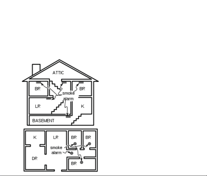
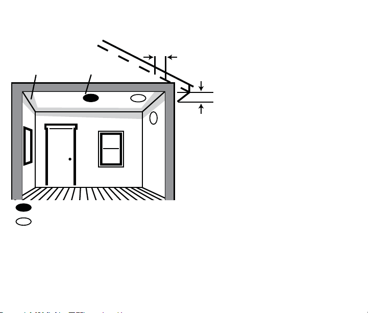
• As close to the center of the ceiling as possible. If this is not practical, put the detector on the ceiling, but no closer than 4 inches (10
cm) from any wall or corner. See fi gure 1.
• If wall mounting is permitted by your local and state codes. Put the
top of wall-mounted detectors between 4 and 6 inches (10 and 15
Page 11
cm) from the ceiling. see fi gure 1.
• Put a smoke detector at both ends of a bedroom hallway if the hallway is more than 40 feet (12 meters) long.
PLACE ONE SMOKE ALARM ON EVERY FLOOR AND SLEEP ROOM
Figure 1: Recommended locations for
smoke alarms
MULTI-STORY
SINGLE LEVEL
Page 12
Dead
Air
Space
Best in
center of
ceiling
No closer than 4 inch
(10 cm) from side wall
Mount on wall at least 4 inch
(10 cm) from ceiling
No more than 6 inches
(15 cm) from ceiling
Best location
Acceptable location
Figure 1.2: Recommended smoke detector mounting locations.
Page 13
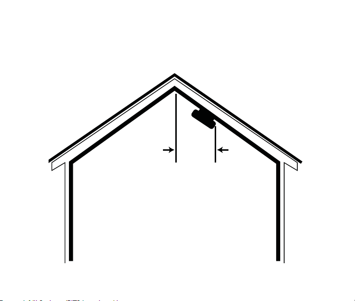
• In rooms with sloped, peaked, or gabled ceilings, mount detectors
within 3 feet (0.9 meters) measured horizontally from the highest
point of the ceiling. See fi gure 2.
Horizontal
distance
from peak
3 feet
(0.9 m)
Figure 2: Recommended smoke detector location in rooms with sloped,
gabled, or peaked ceilings.
Page 14

Where Smoke Detectors Should Not Be Located:
Nuisance alarms are caused by placing detectors where they will not
operate properly. To avoid nuisance alarms, do not place detectors:
• In or near areas where combustion particles are normally present
such as kitchens, in garages where there are particles of combustion from vehicle exhausts, near furnaces, hot water heaters, or gas
space heaters. Install detectors at least 20 feet (6 meters) away from
kitchens and any other areas where combustion particles are normally present.
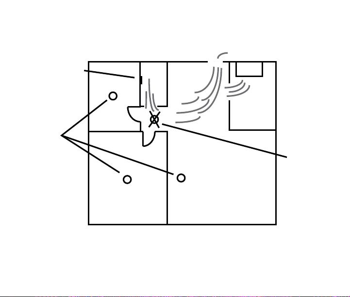
• In air streams passing by kitchens. Figure 3 shows how a detector
can be exposed to combustion particles in normal air movement
paths, and how to correct this situation.
Page 15
Air Flow
Air Return
Bath
Bedroom
Stove
Kitchen
Correct
Incorrect
Bedroom
Figure 3: Recommended smoke detector locations to avoid air streams
with combustion particles.
Living Room
Page 16

• In damp or very humid areas, or next to bathrooms with showers.
The moisture in humid air can enter the sensing chamber as water
vapor, and will cool and condense into droplets that cause a nuisance alarm. Install detectors at least 5 feet (1.5 meters) away from
bathrooms.
• In very dusty or dirty areas. Dust and dirt can build up on the detector sensing chamber and make it overly sensitive, or can block
openings to the sensing chamber and keep the detector from sensing smoke.
• Near fresh air inlets or returns or excessively drafty areas. Air
conditioners, heaters, fans, and fresh air intakes and returns can
drive smoke away from smoke detectors, making the detectors less
effective.
• In dead air spaces at the top of a peaked roof or in the corners between ceilings and walls. Dead air may prevent smoke from reaching the detector. See fi gures 4 and 5 for recommended mounting
location.
• In insect-infested areas. If insects enter a detector’s sensing chamber they may cause a nuisance alarm. Get rid of the bugs before
installing detectors where bugs are a problem.
Page 17

• Near fl orescent light fi xtures. Electrical “noise” from nearby fl ores-
cent light fi xtures may cause a nuisance alarm. Install detectors at
least 10 feet (3 meters) away from such light fi xtures.
Limitations of Smoke Alarms
• Smoke detectors will not work without power. Battery operated
detectors will not work without batteries, with dead batteries, or
if the batteries are not put in properly. AC-powered detectors will
not work if their AC power supply is cut off by an electrical fi re,
and open fuse or circuit breaker, or for any other reason. If you are
concerned about the reliability of either batteries or your AC power
supply for any of the above reasons, you should install both battery
powered and AC powered detectors for maximum safety.
• Smoke detectors must be tested regularly to make sure the batteries
and the alarm circuits are in good operating condition.
• Smoke detectors may not sense fi res that start where smoke cannot
reach the detectors such as in chimneys, in walls, on roofs, or on the
other side of closed doors. If bedroom doors are usually closed at
night, detectors should be placed in each bedroom as well as in the
common hallway between them.
• Smoke detectors also may not sense a fi re on another level of the
residence or building. For example, a second-fl oor detector may not
sense a fi rst-fl oor or basement fi re. Therefore, detectors should be
placed on every level of a residence or building.
Page 18

• The horn in your detector meets or exceeds current audibility
requirements of Underwriters Laboratories. However, if the detector is located outside a bedroom, it may not wake a sound sleeper,
especially if the bedroom door is closed or only partly open. If the
detector is located on a different level of the residence than the
bedrooms, it is even less likely to wake up people sleeping in the
bedrooms.
• All types of smoke detectors have limitations. No type of smoke
detector can sense every kind of fi re every time. In general, detec-
tors may not always warn you about fi red caused by carelessness
and safety hazards like smoking in bed, violent explosions, escaping
gas, improper storage of fl ammable materials, overloaded electrical
circuits, children playing with matches or arson.
• Installing smoke detectors may make you eligible for lower insurance rates, but smoke detectors are not a substitute for insurance.
Homeowners and renters should continue to insure their lives and
property.
Page 19
Test Switch
Green LED
Red LED
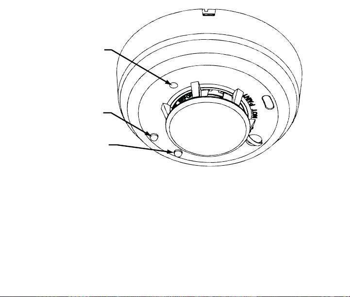
Figure 4: Silent Call Model #SD4-MC(US) Wireless Smoke Detector
Programming
The smoke detector is pre-programmed at the factory.
Transmitter Setting
The Silent Call® system is digitally coded. The Medallion Series SD4MC(US) Smoke Detector is set to a unique million code setting at the
factory and therefore never requires the need of a different code.
Transmitter operates at a frequency of 418MHz.
Page 20

Mounting
First, determine the best location for the smoke detector, one that provides a strong wireless transmission path and proper smoke detection.
A GOOD TRANSMISSION PATH MUST BE ESTABLISHED FROM THE
PROPOSED MOUNTING LOCATION BEFORE PERMANENTLY INSTALLING THE DETECTOR. To check, perform the test described in the TESTING SIGNAL STRENGTH section of this manual. To mount the detector,
perform the following steps:
1. Once a suitable location has been determined, install the mounting
base on the ceiling or on the wall (if local ordinances permit). Use
the two screws and anchors provided.
2. Turn the detector in a clockwise direction in the mounting base until
it clicks into place.
3. Test the detector immediately after completing the installation as
described in the TESTING section of this manual.
Page 21
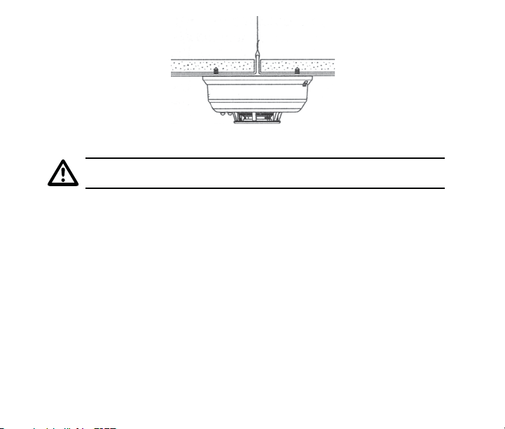
Figure 5: Mount Detector Across Ceiling Panel Support.
DO NOT attach the detector to removable ceiling panels.
Attach the detector across panel support as shown in Figure 5.
Dust Covers are an effective way to limit the entry of dust into the
smoke detector sensing chamber during construction. However, they
may not completely prevent airborne dust particles from entering the
detector. Therefore, it is recommended that the detectors be removed
before beginning construction or other dust producing activity. When
returning the system to service, be sure to remove the dust covers from
any detectors that were left in place during construction.
Smoke detectors are not to be used with detector guards unless the
combination has been evaluated and found suitable for that purpose.
Page 22

Testing the Sensor
Detectors must be tested after installation and following periodic maintenance. The Model #SD4-MC(US) may be tested as follows:
A. Test Switch
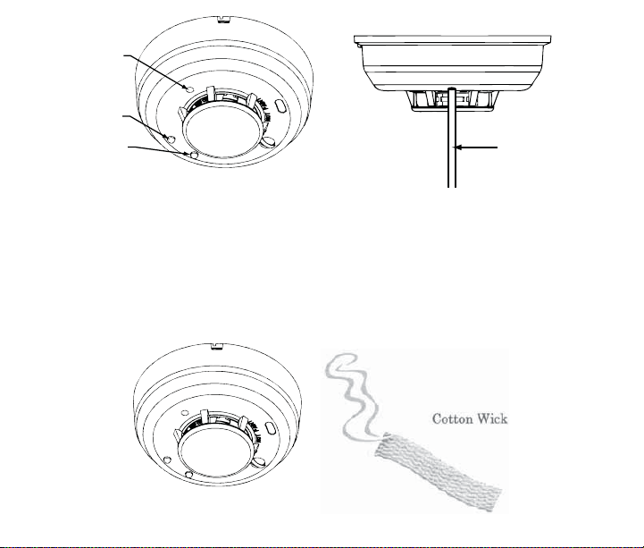
1. A recessed test switch is located on the detector housing
(see Figure 6).
2. Push and hold the recessed test switch for a minimum of 5 seconds.
Use a small screwdriver or Allen key with maximum diameter of
0.18 inch (the detector will trigger and then the smoke detector will
go into alarm thus sending a transmitting signal to the receiver. If
the tool is removed from the recessed switch the sounder will shut
off)
If the detector is within the listed sensitivity limits, the LED on the
detector should blink once per second and the horn should sound within 3 seconds.
Page 23
Test Switch
Green LED
Red LED
PUSH RECESSED
SWITCH WITH A
0.18’ MAX
DIAMETER TOOL
Figure 6: Recessed Test Switch Opening
B. Smoke Entry Test
Hold a smoldering punk stick or cotton wick at the side of the detector and gently blow smoke through the detector until the unit alarms.
Canned aerosol is also an accepted method.
Figure 7: Testing with Wick
Page 24

Testing Signal Strength
A test should be performed before installation to determine a strong
communication path with the receiver and after installation is complete.
Also the owner/user should test the unit at least weekly.
Testing Programming
A test should be performed before installation to ensure the detector
transmitter address is properly programmed to the receiver, and are
operational as a system.
Page 25

Maintenance
NOTE: Power must be removed from the detector before performing
maintenance of any kind by removing the detector’s battery.
1. To ensure proper power-down sequence, battery must be removed
from detector for a minimum of 20 seconds before servicing.
2. Vacuum the cover or use canned air to remove any dust or debris.
3. Using a vacuum or canned air spray carefully clean any dust or debris From Smoke Detector Cover.
4. Reinstall the detector and test. (see the Testing section).
Page 26

What to do in case of fire
• Don’t panic; stay calm. Follow your family escape plan.
• Get of the house as quickly as possible. Don’t stop to get dressed or
collect anything.
• Feel doors with the back of your hand prior to opening them. If a
door is cool, open it slowly. Don’t open a hot door. Keep door and
windows closed, unless you must escape through them.
• Cover your nose and mouth with a cloth (preferably damp). Take
short shallow breaths.
• Meet at the planned meeting place outside your home, and take a
head count to make sure everybody got out safely.
• Call the fi re department from outside. Give your address, then your
name.
• Never go back inside a burning building for any reason.
• Contact your fi re department for suggestions and ideas on how to
make your home safer.
Page 27

FCC INFORMATION NOTICE:
Unauthorized changes or modifi cations could void the user’s authority
to operate the equipment.
This device complies with Part 15 of the FCC Rules. Operation is subject
to the following two conditions: (1) This device may not cause harmful
interference, and (2) this device must accept any interference received,
including interference that may cause undesired operation of the device.
This equipment has been tested and found to comply with the limits
for a Class B digital device, pursuant to Part 15 of FCC Rules. These
limits are designed to provide reasonable protection against harmful
interference in a residential installation. This equipment generates, uses
and can radiate radio frequency energy and if not installed and used
in accordance with the instructions, may cause harmful interference to
radio communications. However, there is no guarantee that interference
will not occur in a particular installation. If this equipment does cause
harmful interference to radio or television reception, which can be determined by turning the equipment off and on, the user is encouraged
to try to correct the interference by one or more of the following measures:
• Reorient or relocate the receiving antenna.
• Increase the separation between the equipment and the receiver
• Connect the equipment into an outlet on a circuit different from that
to which the receiver is connected.
• Consult the dealer or an experienced radio/television technician for
help
Page 28

Specifications
Power Source:
Height:
Diameter:
Weight:
Operating Ambient Temperature Range:
Operating Humidity Range:
Agency Listings:
For Warranty Claims/Repairs Please Contact the Manufacturer:
Silent Call Communications
5095 Williams Lake Road
Waterford, MI 48329
800-572-5227
One 3-volt CR123A Lithium Battery (included).
(Replace with Panasonic CR123A or DURACELL
DL123A)
These batteries are available at local retail stores.
You can also order Replacement Batteries Online
at www.Silentcall.com.
2.3 inches (58 mm)
5.3 inches (135 mm) (with mounting base)
8.5 oz. (241 g) (without battery)
40° to 100°F (4.4° to 37.8°C)
0% to 95% Relative Humidity
Conforms to UL STD 217
 Loading...