

Silent Alert SA3000, FSTX-2225-EU, PG3A-2204-EU, FSCH-2226-IN, CH3A-2205-IN Technical Manual
...
SILENT ALERT SA3000 FIRE SAFE MANUAL 24/04/2015
Designed & Manufactured by Clofield Limited
Free technical helpline 01246 450789 www.silent-alert.co.uk
Silent Alert Fire Safe System
Technical Manual
This manual covers the
FSTX-2225-EU – Fire alarm interface
PG3A-2204-EU – Pager
FSCH-2226-IN Fire Safe Charger or CH3A-2205-IN Alarm clock charger
SW3A-2208-EU SignWave
The Fire Safe interface panel contains electrostatic discharge sensitive components.
Observe antistatic precautions whilst ever the cover is removed.

SILENT ALERT SA3000 FIRE SAFE MANUAL 24/04/2015
Designed & Manufactured by Clofield Limited
Free technical helpline 01246 450789 www.silent-alert.co.uk
TECHNICAL SPECIFICATION
Introduction
The Silent Alert Fire Safe system alerts people who are deaf when a fire alarm is activated; it
comprises a fire alarm interface and one or more compatible receivers. The fire alarm interface
links to a fire alarm panel via a volt free relay and incorporates a radio transmitter. When the fire
alarm is activated the transmitter within the fire alarm interface sends out a coded radio signal.
When a Pager receives this signal it vibrates and lights a fire key on the Pager display. The
system is designed to comply with all relevant parts of BS5839-1 2013 & EN54-2 and MUST be
installed by a competent person as defined in BS5839-1 2002.
Installation Training
Installation training is available; please call us on 01246-450789 for more details.
Fire Safe Interface Panel
Part Number: FSTX-2225-EU
Dimensions: H300mm x W210mm x D160mm
Weight: Without Battery 1.50 KG - With battery 2.3KG
Material: Polycarbonate self-extinguishing enclosure.
Protection: Water resistant
Power Supply: 240v AC 50 Hz
Battery back up: 6volt lead acid 4Ah (Yuasa Type Y4-6) Dimensions
H100mmxW47mmxD70mm
Alarm Panel feed to Fire Safe Panel: Normal condition 5-30 Volts DC.
Grounded in alarm mode via an integral OPTO isolated voltage fed relay.
Fault signal to Fire Panel: Via an integral normally open or normally closed volt free relay.
Fault conditions: Mains failure, battery removal or charge failure,
PCB failure, radio failure
Radio compliance: In accordance with EN300 220-1.
Radio licence: Licence exempt
Range: Up to 1000m in open air
Pager Unit
Part number: PG3A-2204-EU MKIII
Dimensions: H63mm x W82mm x D26mm (Excluding belt clip)
Weight: 74gms
Material: Impact resistant ABS
Power supply: Integral NiMH 3.6Volt rechargeable battery pack.
Charger: Intelligent boost, trickle and maintenance charging.
Fault conditions: Low battery & radio failure.
Radio compliance: In accordance with EN300 220-1.
Radio licence: Licence exempt.
Range: Up to 1000m in open air.
Other: Integral field strength / data validation meter for system commissioning.

SILENT ALERT SA3000 FIRE SAFE MANUAL 24/04/2015
Designed & Manufactured by Clofield Limited
Free technical helpline 01246 450789 www.silent-alert.co.uk
SignWave Unit
Part number: SW3A-2208-EU
Dimensions: H140mm x W50mm x D70mm (Excluding belt clip)
Weight: 278gms
Material: Impact resistant fire retardant ABS
Power supply: Integral NiMH 6Volt rechargeable battery pack.
Charger: Intelligent boost, trickle and maintenance charging.
Fault conditions: Low battery & radio failure.
Radio compliance: In accordance with EN300 220-1.
Radio licence: Licence exempt.
Range: Up to 1000m in open air.
Other: Integral field strength / data validation meter for system commissioning.
Preliminary radio coverage test
A preliminary radio coverage test is normally conducted prior to installation to ensure total
coverage throughout a building. It is recommended that a further radio coverage test is
performed prior to permanently securing the Fire Safe panel to a wall in case it needs to be
relocated. The Fire Safe panel should be mounted temporarily to a wall at between 1.5 and
1.75 meters from the ground away from large metal objects and lift shafts. For best results
locate the panel central to the building. In multi-storey buildings penetrations through steel
re-enforced concrete floors may be poor. In these situations coverage would be improved if
the panel is located one floor above ground level to provide coverage over three floors or
two levels above ground level to cover four floors. In-building coverage will vary from
building to building therefore it is essential that a full and thorough radio coverage test is
conducted. The range test procedure detailed later under the heading Site Survey should
be followed. If it is found that the coverage is inadequate then additional Fire Safe interfaces
may need to be added. In this case it will be necessary to change the signal patterns for
each panel to ensure there are no standing wave problems. This aspect is covered in more
detail under the heading The use of more than one Fire Safe panel below.
Power Supply
It is necessary to supply the Interface Panel with a dedicated mains supply (220-240v AC 50
Hz) via its own un-switchable fused spur. The mains terminal block is located at the bottom left
hand side of the main PCB and is marked Earth (top) Neutral (middle) Live (bottom). The Panel
will also require a 6 Volt lead acid 4Ah back-up battery Type Y4-6 (Dimensions
H100mmxW47mmxD70mm).
It is necessary to connect the battery to the two wires with crimped connectors, before
connecting the mains to avoid a fault condition.
SILENT ALERT SA3000 FIRE SAFE MANUAL 24/04/2015
Designed & Manufactured by Clofield Limited
Free technical helpline 01246 450789 www.silent-alert.co.uk
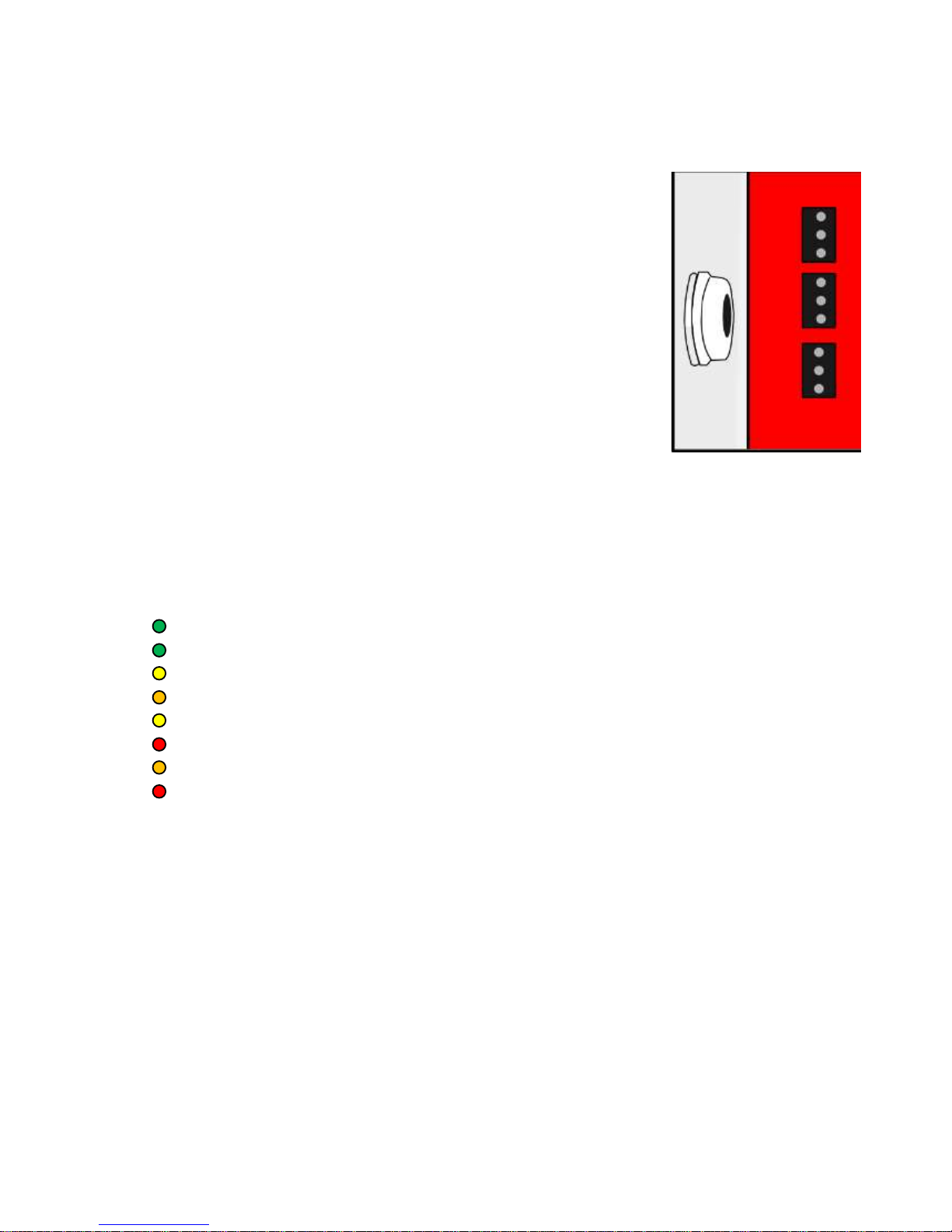
Alarm Output from main fire alarm panel
It is possible to trigger the unit by the removal of an external voltage using the bottom I/O
terminal.
The Interface Panel requires an external voltage of at least 5 – 30V AC
or DC.
NOTE the maximum voltage must not exceed 30v AC or DC or damage
will occur to the panel invalidating warranty.
Fault conditions from Fire Safe panel
The Fire Safe panel has a fault output to the main fire alarm panel
provided via the top terminal block. A fault condition on the Fire Safe
panel will cause a relay to be closed that will create an open circuit
between common and normally closed (N/C) and a closed circuit
between normally open (N/O) and common.
A fault alarm will be given in the following conditions:
Mains failure
Battery charge failure or removal
Loss of radio signal
Main PCB failure
Front Panel Indicator Lights
Mains Green Lit when mains power present
Battery Green Lit when battery present
Charging Yellow Lit whilst battery is charging
Fault Orange Lit when any of the above fault conditions occur
Poll Yellow Lit constantly, goes out when poll signal is sent
Alarm Red Lit when alarm signal received from fire panel
Disable Orange Lit when disable key is turned to the on position
Test Red Lit when in range test mode.
GND
N/C
N/O
COM
 Loading...