

Silencer 30SL Installation Manual
INSTALLATION MANUAL
This unit is designed for professional installation only and
must be installed by an authorized Silencer dealer.
Please visit our website at www.magnadyne.com
For Warranty information:
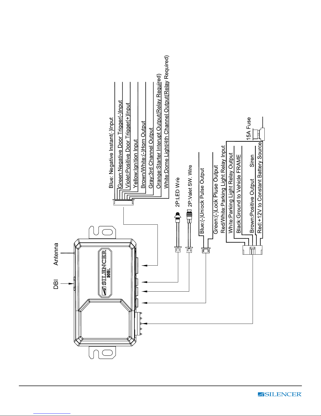
INSTALLATION DIAGRAM
for
IM-FULL-30SL rev A 2
MAIN POWER CONNECTOR
RED / WHITE: PARKING LIGHT RELAY INPUT
WHITE: PARKING LIGHT OUTPUT
BLACK : MAIN SYSTEMS GROUND
BROWN : POSITIVE SIREN OUTPUT
RED : FUSED 12 VOLT (+) BATTERY POWER
3 PIN, DOOR LOCK CONNECTOR
1. Blue
3. Green
Wire
Wire
( - ) Unlock Pulse
( - ) Lock Pulse
8 - PIN ACCESSORY CONNECTOR
GRAY WIRE / CHANNEL 3 NEGATIVE TRUNK OUTPUT
ORANGE :STARTER INTERRUPT O/P RELAY REQUIRED
YELLOW / IGNITION INPUT (+)
GREEN / (-) DOOR TRIGGER INPUT
BLUE / (-) INSTANT TRIGGER INPUT ( HOOD, TRUNK)
VIOLET / (+) DOOR TRIGGER INPUT
BROWN/ WHITE / (-) HORN OUTPUT.
WHITE: DOME LIGHT OUTPUT(OR CH#4 O/P) RELAY REQUIRED
WIRING
Keep wiring away from moving engine parts, exhaust pipes and high-tension cable. Be sure to tape wires that pass
through holes on the rewall to prevent fraying.
CAUTION: Do not connect the wire harness to the control module until all wiring to vehicle is complete.
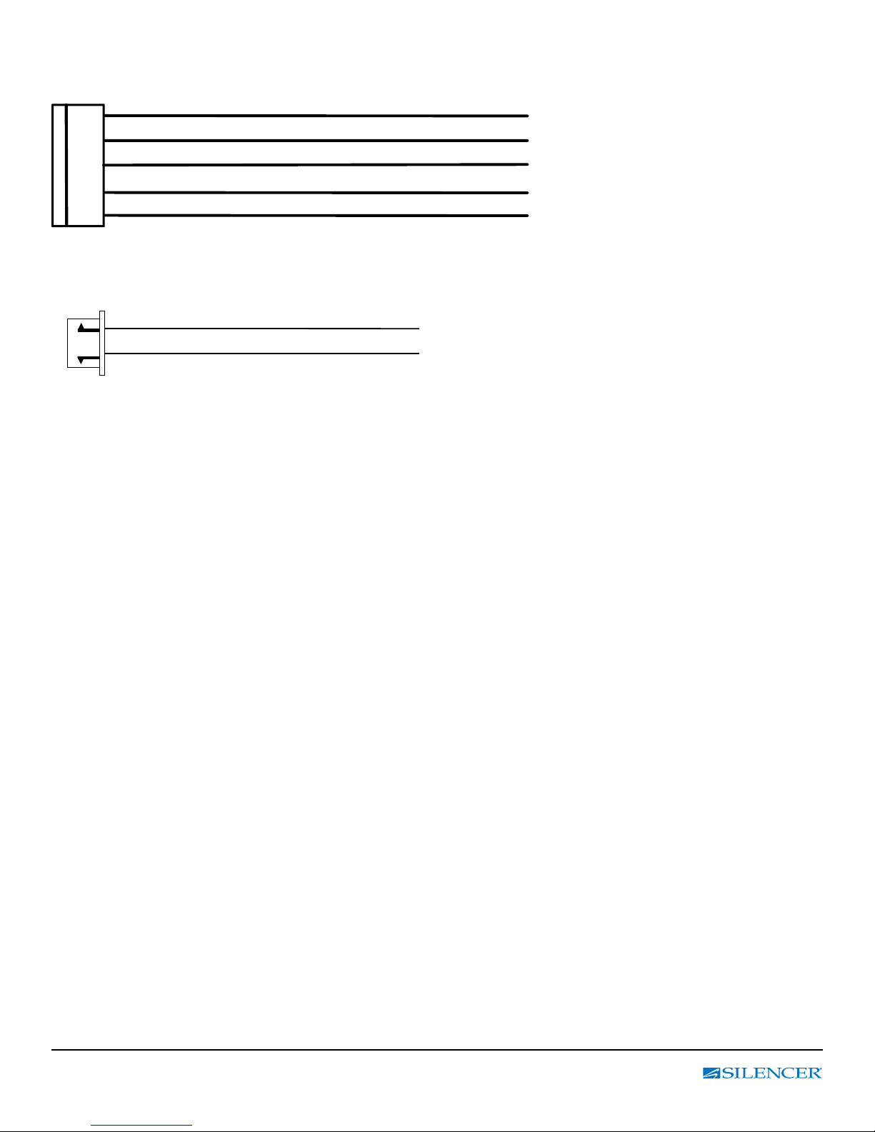
2 PIN CONNECTOR (THE LED STATUS INDICATOR)
The led indicator status should be mounted in a highly visible area such as the top of the dashboard, on top of the shifter
console or on the dashboard face. Leave at least 6mm space behind the mounting location for LED housing. Once a
suitable location is chosen, drill a 6mm hole. Run the LED wires through the hole, then press the 2 pin LED housing into
place. Route the LED wires to the control module.
IM-FULL-30SL rev A 3

5 PIN WIRE HARNESS
RED / WHITE WIRE –PARKING LIGHT RELAY INPUT —
The RED/WHITE wire is the input to the ashing parking light relay. The connection of the RED/WHITE wire
will determine the output polarity of the ashing parking light relay.
If the vehicle you are working on has +12volt switched parking lights, you don’t need to connect this wire.
This wire is already connected to +12volt.
If the vehicle’s parking lights are ground switched, cut the RED/WHITE wire and connect it to the chassis ground.
WHITE WIRE — PARKING LIGHT RELAY OUTPUT
(+12 V 10A OUTPUT) —
Connect the WHITE wire to the parking light wire coming from the headlight switch. Do not connect the WHITE wire to the
dashboard lighting dimmer switch. (Damage to the dimmer will result). The limitation of the WHITE wire is 10 AMP max.
Do not exceed this limit or damage to the alarm and parking relay will result.
BLACK WIRE — SYSTEM GROUND –
This is the main ground connection of the alarm module. Make this connection to a solid section of the vehicle frame.
Do not connect this wire to any existing ground wires supplied by the factory wire loom, make the connection to the
vehicle’s frame directly.
BROWN WIRE – (+) SIREN OUTPUT –
This wire provides power to the supplied siren. Connect the Brown wire to the Red wire of the siren.
Connect the Black wire of the siren to a stable chassis ground.
RED WIRE — SYSTEM POWER (+12V CONSTANT) —
The RED wire supplies power to the system. Connect this wire to a stable constant +12 volt source.
2 PIN BLUE CONNECTOR FOR THE VALET SWITCH
Select a mounting location for the switch that is easily accessible to the driver of the vehicle. The switch does not have to
be concealed, however, concealing the switch is always recommended, as this provides an even higher level of security to
the vehicle. Mount the valet switch in a hidden but accessible location. Route the valet switch wires to the control module.
8 - PIN ACCESSORY CONNECTOR
GRAY WIRE / CHANNEL 3 NEGATIVE TRUNK OUTPUT
ORANGE :STARTER INTERRUPT O/P RELAY REQUIRED
YELLOW / IGNITION INPUT (+)
GREEN / (-) DOOR TRIGGER INPUT
BLUE / (-) INSTANT TRIGGER INPUT ( HOOD, TRUNK)
VIOLET / (+) DOOR TRIGGER INPUT
BROWN/ WHITE / (-) HORN OUTPUT.
WHITE: DOME LIGHT OUTPUT(OR CH#4 O/P) RELAY REQUIRED
IM-FULL-30SL rev A 4
 Loading...