

Silence Aircraft Twister Kit Assembly Manual

Revision 1.6
ii
S ilence-Aircraft GmbH,
Kapellenweg 54a,
33415,
Verl
Germany
Aircraft Assembly
Manual
Twister Kit
Revision 1.6

Revision 1.6
iii
Table of Contents
0. Using this Manual
1. General
1.1 Specifications
1.2 Materials and Tools
1.3 Fiber Composite Basics
1.4 Safety
2. Wings
2.1 Flaps
2.1.1 Installing the Hinge Pin for the Flap and the Aileron
2.1.2 Installing the Connecting Pins
2.1.3 Installing the Counterweight
2.1.4 Laminating the Seams and Ribs
2.2 Ailerons
2.2.1 Installing the Hinge Pins
2.2.2 Installing the Aileron Horns with Self-Aligning Bearings
2.2.3 Installing the Counterweights
2.2.4 Laminating the Seams and Ribs
2.3 Wings
2.3.1 Installing the Outboard Self-Aligning Bearing for the Aileron
2.3.2 Installing the Mounting Bearing for the Flap
2.3.3 Installing the Root Rib
2.3.4 Cutting the Holes for the Counterweights
2.3.5 Cutting the Wheel Well
2.3.6 Installing the Fuel Tanks
2.3.7 Installing the Aileron Drive
2.3.8 Installing the Flap and the Aileron
2.3.9 Installing the Bearing Sleeve for the Front Wing Torsion Pin
2.3.10 Laminating the Seams and Ribs
2.3.11 Installing the Pitot Tube (for Airspeed Indicator)
2.3.12 Installing the Position Lights (Optional)
3. Fuselage
3.1 Reinforcing the safety cell around the lap safety belt

Revision 1.6
iiii
3.2 Installing the flap mechanism and the supports for the wing torque tube
3.3 Installing the landing-gear struts, wheels and fairings
3.4 Installing the landing-gear actuator
3.5 Installing an undercarriage warning system PFA MOD 329/007
3.6 Installing the horizontal stabilizer with securing wire
3.7 Installing the ribs in the rudder assembly
3.8 Mounting the wings
3.9 Installing the fuselage base
3.10 Installing the elevator bellcrank
3.11 Assembling the rudder
3.12 Installing the upper rudder bearing
3.13 Assembling and installing the rudder drive in the rudder
3.14 Installing the rudder pedals
3.15 Assembling and installing the tail wheel
3.16 Assembling and installing the control stick
3.17 Installing the elevator push rods incorporating PFA MOD 329/003
3.18 Assembling and fitting the canopy
3.19 Installing the NACA air supply
3.20 Installing the trim
3.21 Laminating the seams and reinforcing the wheel well
3.22 Installing the baggage compartment cover, safety belt and seat pan
3.23 PFA MOD 329/008 Parachute Seatback
4. Tail
4.1 Installing the Root Ribs and Laminating the Seams
4.2 Inserting the Outboard Hinge Pin and the Self-Aligning Bearing
into the Fin
4.3 Installing the Elevator Supports
4.4 Installing the Fiberglass Hexagon Tube and the Root Rib into
the Elevator
4.5 Installing the Plain Bearing for the Front Elevator Torsion Tube
5. Motor
5.1 Painting and Masking the Firewall
5.2 Installing the Engine Mount on the Firewall including PFA MOD329/005
5.3 Installing the Engine on the Engine Mount

Revision 1.6
ivi
5.4 Installing the Cooling Air Ducts
5.5 Installing the Air-Intake Casing
5.6 Installing the Crankcase Ventilation with Separator
5.7 Mounting the Propeller and the Spinner
5.8 Assembling the Throttle and Brake Assembly
5.9 Installing the Control Cables on the Engine
5.10 Installing the Tank and Fuel System Incorporating PFA MOD 329/002
5.11 Installing the Cowling
6. Avionics
6.1 Selecting and Arranging the Instruments
6.2 Creating the Cut-Outs in the Instrument Panel
6.3 Rounding the Cut-Out Edges
6.4 Laminating the Instrument Panel
6.5 Installing the Instrument Panel in the Fuselage
6.6 Creating the Structure behind the Instrument panel
6.7 Wiring Loom
6.8 PFA MOD329/001 Removing and disabling Emergency Flap lowering switch
System
7. Surface Treatment and Painting
7.1 Filling and Sanding the Surface
7.2 Filling and Sanding the Seams
7.3 Priming
7.4 Wet Sanding
7.5 Painting/Paint Selection
Revision 1.6
vi
0 Using this Manual
Note: This manual was translated from a German original.
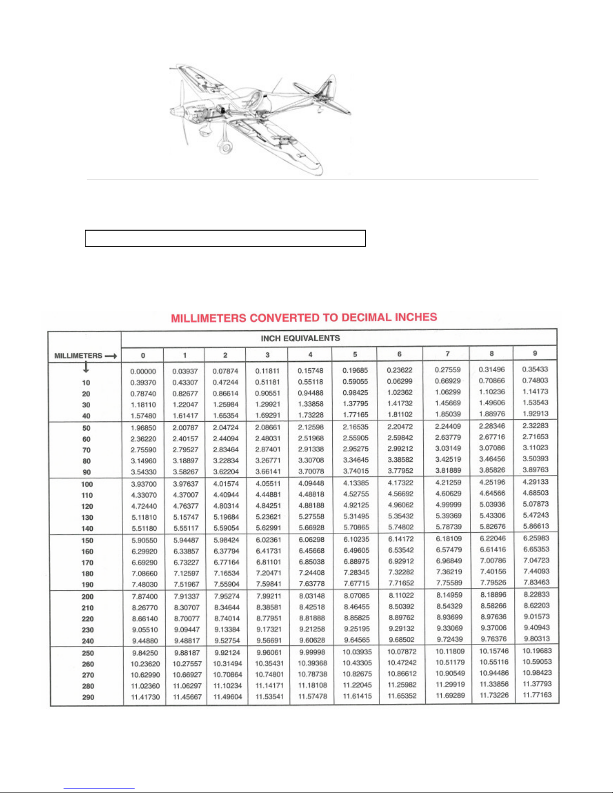
Measurements
The design of the Twister is based on the metric system. All US conversions given in the text are
for guidance only. All dimensions in the figures are in millimeters (mm) unless otherwise stated.

Revision 1.6
ii
Part Numbers
The part numbers refer to the bill of materials, which is delivered as a separate document.
Printing the Manual
The layout of this manual is adjusted for letter size paper.
Abbreviations
CF cotton flock
MB microballoons
FRP fiber-reinforced plastic
FC fiber composite
UD unidirectional
General g uide line for the installation of bolts.
It is standard aircraft practice to always orient bolts pointing down, outboard, or aft, when possible.
Also, the bolt grip length should equal the material thickness it is going through to avoid having the
threads in bearing, and when using self locking nuts, make sure there are at least 1-1/2 threads
showing.
You should not be able to thread the nuts on by hand, if so the locking feature is worn out. The best
practice it to n ot reuse self locking nuts or at least minimize their re-use. When securing with
Loctite, always mark it with witness paint, indicating it has been secured with Loctite.
If you need to remove a fastener secured with Loctite use a heat gun to soften the bonding agent so
not to cause damage to the threads.
If a bolt is not clamping or the material it is going through is rotating against the bolt, a castle nut
and cotter pin must be used.
Revision 1.6
1.1
General
1
1.1 Specifications
The Twister kit consists of structural components made from honeycomb fiber glass composites,
with spars and additional reinforcements made of carbon fiber reinforced plastic. For extra safety, an
aramid honeycomb monocoque (cockpit cell) is used.
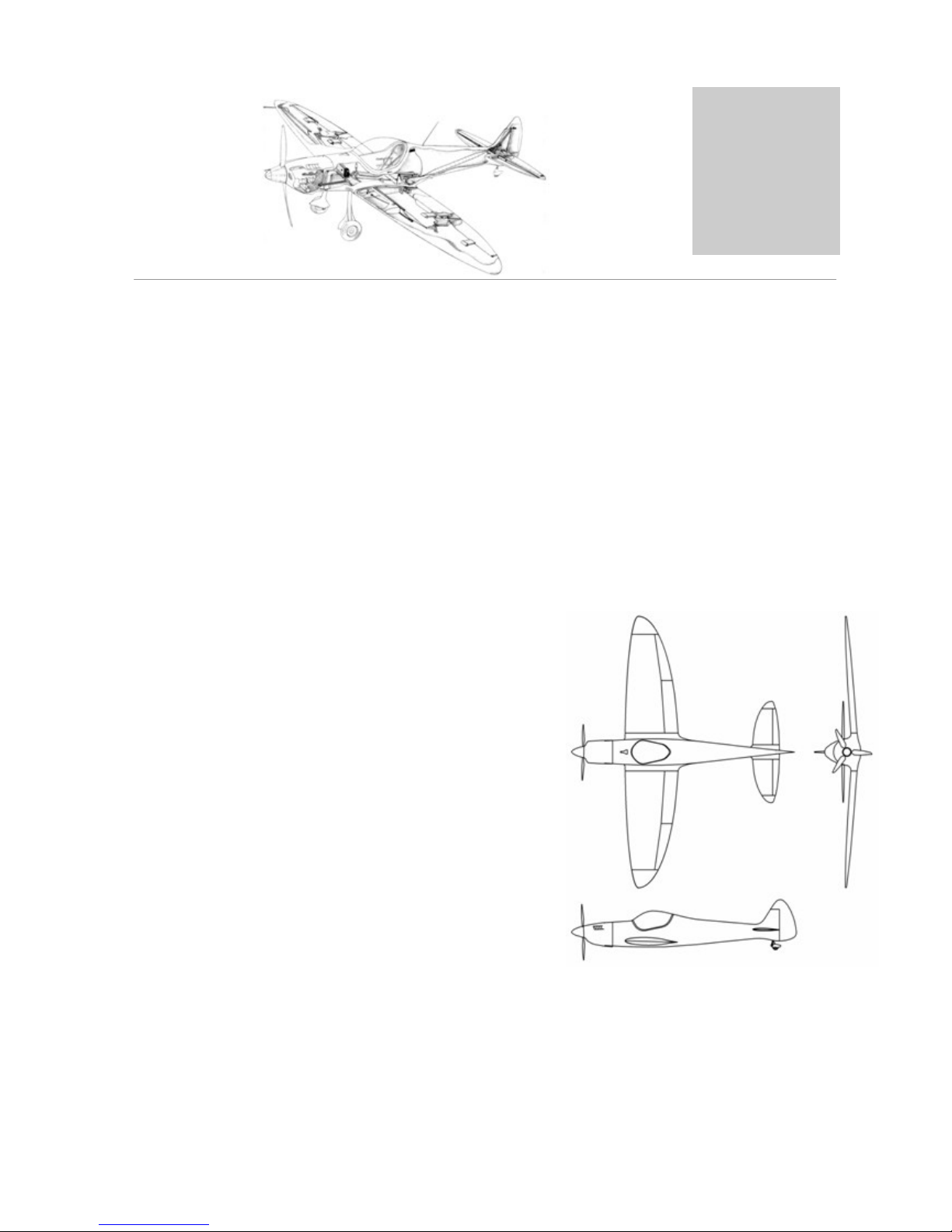
The Twister is an aerobatics -capable cantilever low-wing plane with cruciform tail unit, retractable
two-wheel landing gear and flap system. Optionally a rescue system can be installed in the cockpit cell.
There are two fuselage variants: one prepared for mounting a rescue system and one for use without a
rescue system.
Wing span: 7.5 m (24.6 ft)
Length: 6.18 m (20.28 ft)
Wing area: 8.718 m² (93.84 sq ft)
Max. take-off weight (MTOW): 420 kg (881.95 lb)
Max. wing loading: 40.15 kg/m² (8.22 lb/sq ft)
Elevator span: 2.8 m (9.19 ft)
Elevator area: 1.65 m² (17.76 sq ft)
Crew: 1
Engine: Jabiru 2200

Revision 1.6
1.2
General
1
Strength
The Twister is certified for the following load factors:
+6 / -4g at 400 kg (882 lb) take- off weight at 209 km/h (113 kt/130 mph) maneuvering speed
Do not exceed these load factors. Especially, avoid wide rudder movements at speeds above
209 km/h (113 kt/130 mph).
Maximum Flight Speeds
Speeds converted for sea level
Stall speed, 30° flaps: VSF 75kph (40.47kt/46.60mph)
Stall speed, no flaps: VS 85kph (45.87kt/52.82mph)
Maneuvering speed: VA 209kph (112.78kt/129.87mph)
Maximum speed: VNE 300kph (161.88kt/186.41mph)
V
D
330kph (178.07kt/205.05mph)
Maximum speed, 30° flaps: VFE 125kph (67.45kt/77.67mph)
When using a rescue system, the maximum speed is limited to the maximum speed specified for the
rescue system.
Load calculations are based on JAR23.
 Loading...