


1
USER MANUAL
SCUTUM S02

2
GENERAL CONTENTS
1.- General characteristics of the vehicle
2.- Technical specifications of the battery and charger
3.- Maintenance program
4.- Warranty of the Vehicle and the battery

3
GENERAL CHARACTERISTICS OF THE VEHICLE
0. GENERAL SPECIFICATIONS
1. VEHICLE IDENTIFICATION
1.1 VIN - FRAME MARKING
1.2 INFORMATIVE LABEL - PRODUCTION PLATE
1.3 MAXIMUM PERMITTED LOAD
2. GENERAL COMPONENTS
2.1 MAINSTAND AND SIDESTAND
2.2 MIRRORS
2.3 FUSE BOX
2.4 REAR WHEEL (MOTOR)
2.5 LIGHTS
2.6 UNDER SEAT STORAGE COMPARTMENT
2.7 TAIL BOX
3. CONTROLS
3.1 LEFT SWITCH CONTROLS
3.2 COMBINED BRAKE AND REGENERATIVE BRAKE
3.3 RIGHT SWITCH CONTROLS
3.4 IGNITION SWITCH
3.5 KEY GUARD
4. INSTRUMENT PANEL
4.1 SPEEDOMETER
4.2 PANEL
5. DISPLAY
5.1 MAPING OF THE ELECTRIC MOTOR
5.2 SERVICE
5.3 READY AND BATTERY, MOTOR AND CONTROLLER TEMPERATURES
5.4 VEHICLE CHARGE INDICATOR
5.5 SPEEDOMETER ERRORS

4
GENERAL SPECIFICATIONS
Motor
Type
Specifications
Motor (maximum torque / maximum power)
Type
Maximum speed
Position
161.4 Nm / 4 KW
BRUSHLESS HUB MOTOR 13”
80 Km/h
On wheel
Regenerative brake
Motor brake
Reverse speed
0 Emissions
LED lighting
Battery specifications
2 kWh (Pack 1)
4 kWh (Pack 2)
6 kWh (Pack 3)
Capacity
Cell chemistry
Weight
Battery nominal voltage
2200 kWh 44 Ah
Lithium-ion cells
19.5 Kg
48 V
4200 kWh 82.5 Ah
Lithium-ion cells
30.2 Kg
48 V
5500 kWh 107.3 Ah
Lithium-ion cells
35.8 Kg
48 V
Charger Type
Standard charging time
On-board 600 W
3 hours 100%
On-board 600 W
6 hours 100%
On-board 600 W
8 hours 100%
Riding modes & maximums
2 kWh (Pack 1)
4 kWh (Pack 2)
6 kWh (Pack 3)
Maximum speed
Maximum range
E 25 km/h
E 65 km
C 40 km/h
C 45 km
S 45 km/h
E 40 km
E 45 km/h
E 120 km
C 60 km/h
C 90 km
S 75 km/h
E 80 km
E 45 km/h
E 180 km
C 60 km/h
C 130 km
S 75 km/h
E 110 km

5
Frame
Specifications
Material
Wheel base
Height from ground
Seat height
Weight without battery
Maximum carrying capacity
Steel
1910x710x1260 mm
1482 mm
137 mm
85 Kg
175 Kg
General specifications
Specifications
Wheels
Tyres
Front tyre pressure
Rear tyre pressure
Brakes
Front / rear suspension
Suspension
13”X3.5
130/60-13
1.8 bar
2.5 bar
220 mm disc
Hydraulic with 232 oil
Front telescopic fork
Accessories (optional)
Tail boxes
Document holder on leg guard
Windshield
Smartphone support and charger
Factory remote connection
Electronic data registers
Safety
Protection against short circuits.
Protection against voltage dips and surges.
Protection for low and high voltage.
Protection against high temperatures of the engine, battery and controller.

6
1. VEHICLE IDENTIFICATION
1.1 VIN - FRAME MARKING
The VIN is an alphanumeric 17-digit code which is used to identify your scooter. The VIN standard is established by the ISO
laws. The VIN is required when ordering spare parts.
The VIN is stamped on the steering pipe, below the plastic cover. It is engraved directly on the frame.
To access the VIN, remove the plastic cover by applying pressure to the upper part of the cover.

7
1.2 INFORMATIVE LABEL - PRODUCTION PLATE
This scooter has a label which displays the frame number, the maximum permitted noise level and the rpm.
The label is at the rear of the scooter, towards the right side, very close to the wheel.
1.3 MAXIMUM PERMITTED LOAD
The maximum weight of this scooter is 315 kg, including the rider and the maximum carrying capacity. This weight limit
is shown in all the specifications tables.

8
Maximum Total Weight 315 kg.
Maximum Total Load 170 kg.
Maximum Load in Central Zone Not Specified
Maximum Capacity in Under Seat Storage Compartment 3.7 Litres
Maximum Capacity in Tail Box 75 kg.
Center of the
scooter
Underseat luggage
compartment
Space for a
rear box

9
2 GENERAL COMPONENTS
The general components of this scooter are:
Front fender
Speedometer
Rear
Mirrors
Seat
Front wheel
Battery
Sidestand
Mainstand
Rear wheel
(Motor)
Break light,
Blinkers

10
2.1 MAIN STAND AND SIDE STAND
SIDE STAND
The side stand is on the left side of the scooter.
To use the side stand, push the bar downwards with your
foot from the side support.
The side stand is used when the ground is too uneven, or
sloped to use the main stand.
MAIN STAND
The main stand is underneath the scooter centre line.
This stand is used to keep the scooter in a vertical position.
To lower the stand, push the arm down with one foot while
slowly pushing the scooter forwards and upwards.
The main stand is used when the ground is even and flat
and when the scooter is going to be parked for a long
period of time.
Both stands are reinforced at the fastening point in order to
withstand intensive pressure throughout use.

11
2.2 MIRRORS
Before driving, make sure that the mirrors are
correctly adjusted.
It is possible to adjust them just by moving the
plastic part.
2.3 FUSE BOX
The fuse box is below a protective cover inside the
under seat storage compartment.
If any electronic anomalies are detected, please
contact your official dealer.

12
2.6 UNDER SEAT STORAGE COMPARTMENT
To open this compartment, insert the key in the lock and
turn it clockwise, then pull the seat upwards.
To lock the seat, lower the seat and press down until it locks
into the fitting.
The maximum carrying capacity in this compartment is 3.7
litres.
The power cable for charging the vehicle is also stored in
this compartment.
2.4 REAR WHEEL (MOTOR)
This scooter has a 100% electric motor on the rear
wheel, with Brushless (HUB) technology with direct
transmission and cooled by air.
It has a power of 4000 W and reaches a maximum
speed of 80 km/h.
2.5 LIGHTS
All the lighting on the scooter is LED-based, including
the dipped and main beam headlamps.

13
2.7 TAIL BOX (optional)
This scooter has a platform suitable for fitting a tail box with a maximum carrying capacity of 75 kg, designed for the safe
assembly of boxes with different specifications. Scutum has a 200l Box that can be installed in the scooter.

14
3. CONTROLS
Left Switch Controls
Right Switch Controls
Rear brake / Parking brake
Front brake /
regenerative brake
Throttle
Ignition /
Key guard

15
3.1 LEFT SWITCH CONTROLS
Light switch positions
o Position 1 DIPPED BEAM HEADLAMP
When the vehicle is switched on, the dipped lights come on by default (with the selector switch in position
1). The blue light on the speedometer does not light up when the selector switch is in position 1.
o Position 2 MAIN BEAM HEADLAMP
To switch on the main beam headlamp, press the upper part of the switch.
The blue light on the speedometer lights up when the selector switch is set to position 2.
Position 1
Position 2

16
Turn signal selector switch
To switch on the turn signal, move the switch to the right to indicate a turn to the right or move the
switch to the left to indicate a turn to the left. Press the white central button to reset the position of
the turn signal switch.
Horn
Press the red button to sound the horn.
Reverse speed selector switch
This scooter has a reverse speed. To operate reverse speed, press and hold the button behind the
left brake lever, and gently accelerate.
Proceed with caution, especially the first time. This operation helps to manoeuvre the scooter when
parking or when reversing out of a parking space.

17
Run Button
Selector Switch
Lights
Selector Switch
Horn

18
3.2 COMBINED BRAKE AND REGENERATIVE BRAKE
This scooter is fitted with a combined brake system that
operates as follows:
The right brake (mechanically) brakes the front wheel and
activates the regenerative brake (electronically) of the
rear wheel, while the left brake brakes (mechanically)
both the front and back wheels.
The regenerative brake has its own control on the right
brake lever, allowing it to be used without activating the
mechanical brake.
How to brake using the regenerative brake:
1.- Press the first part of the front brake lever (right) to
activate the regenerative brake.
This system electronically brakes the rear wheel and
regenerates energy to the battery.
2.- If you continue pressing the brake lever, the front
wheel brake is activated; the greater the pressure the
greater the force of the mechanical braking.
Braking with the regenerative brake helps the braking
and it also helps to keep the battery charged.
Regenerative Brake
Mechanical Brake
The force of the regenerative brake depends on the
mode selected (Eco (without regenerative), City
(with regenerative), Sport (with much regenerative)).

19
3.3 RIGHT SWITCH CONTROLS
Throttle
Turn the accelerator downwards to accelerate.
Release the throttle to return to a neutral position.
Warning switch
Right position - All lights off, default setting.
Left position - Warning signal
4 turn signals operating
Riding mode selector switch. “MODE”
This Scooter has three different riding modes:
Press once to change between the ECO, CITY or SPORT modes.
CITY “C”: The vehicle is designed to operate normally in CITY “C” mode, giving the vehicle a good performance level and a
more balanced consumption.
SPORT “S”: This riding mode offers greater power and speed in specific cases. Frequent use of the SPORT mode reduces the
scooter’s range (total range in Km with load), due to the increased power consumption, and may also result in overheating of the
engine/battery, leading to reduced performance or the disconnection of the scooter.
ECO “E”: this mode offers a more relaxed style of riding, with limited speed and acceleration. The speed is limited to 45km/h.
This modes extends the vehicle’s operating range.
The MODE button is also used as the start button. To start the vehicle the MODE button should be held pressed down for 1
second after switching on the scooter. To confirm that the vehicle is started, the word READY is displayed on the screen,an
acoustic signal is heard and the green LED on the speedometer lights up.
MODE selector
Warning switch

20
3.4 IGNITION SWITCH
Selector switch positions
STEERING LOCKED
Turn the handlebar to the left as far as possible.
Insert the key and turn anti-clockwise.
All the functions are deactivated.
The Scooter has very limited movement.
OFF / STEERING UNLOCKED
All the functions are deactivated.
The steering lock is not activated.
The Scooter can be moved.
It is possible to work on the motorcycle in safety.
IGNITION
All functions are ready for use.
The Scooter is ready to be ridden if the MODE button is
held down for one second, READY is displayed on the
speedometer and a green LED lights up.
In this position, the key cannot be removed.
3.5 KEY GUARD
CLOSED
Place the interior side section of the key in the groove.
Turn anticlockwise to protect the switch.
OPEN
Turn clockwise to open and then it is possible to
access the ignition key.
Ignition Switch
Key Guard

21
6.
Charging
4. INSTRUMENT PANEL
Speedometer
Panel
1. Speed
Indicator
2.
Mode
3.
Trip
4.
Stand
7.
Low Battery
8.
Right Turn Signal
9.
Reverse Speed
10.
Dipped Beam
11.
Diagnosis
12.
Left Turn Signal
13.
Screen
5. Temp.
warning

22
4.1 SPEEDOMETER
1.- SPEED INDICATOR
Indicates current speed. This can be read in kilometers per
hour or in miles per hour.
2.- MODE BUTTON
Functions that can be selected with the speedometer
MODE button:
AVG - Average speed of the TRIP selected (TRIP1 or
TRIP2)
TIME - Duration of the partial selected (TRIP1 or TRIP2) in
the format hh: mm: ss.
ODO - odometer (Km indicator)
Temp. B: temperature of Battery Pack
Temp. E: Engine temperature
Temp. C: Controller temperature
All temperatures are given in centigrade degrees.
3.- PARTIAL BUTTON
There are 2 different modes. Press the button to change
between T1 and T2. The user can restore the trip values by
pressing the button for at least 2 seconds.
TRIP1: The value is deleted each time the engine is
switched off (up to 999.9 km).
TRIP2: Deleted only by the user (up to 999.9 km).
To change the hour of the clock you have to see in the display
ODO (press MODE until it appears), then press MODE and
TRIP simultaneously until the first number starts to blink.
Pressing the MODE button will increase its value and
maintaining it will change to minutes.
4.2 PANEL
4 -. LED - Yellow, on when the side stand is open.
5 -. LED - Red, Temperature warning.
6 -. LED - Yellow, the regenerative brake is on.
7 -. LED - battery low- In Yellow, on when the battery voltage is
less than 25%.
8 -. LED - Green when indicating a right turn.
9 -. LED - Yellow, reverse speed in use.
10 -. LED - Blue, indicates main beam on.
11 -. LED - Green, indicates correct engine operation.
12 -. LED - Green when indicating a left turn.

23
5. DISPLAY
This displays the true operation of all the segments.
This displays the true operation of all the
segments of the screen (as in the figure
above, but with other data).
Different screen views are possible:
Odometer (7380), TRIP 2 (286.0) and the
battery charge level (82%).
Operating time (10 h: 48 m: 48s) and the
current battery charge level (38%)

24
Screen
Map
E Eco
C City
S Sport
v.2 Displays ECO map
5.1 MAP OF THE ELECTRIC MOTOR
This displays the selected map of the electric motor.
Example of screen when vehicle is switched on, 3000 km
remaining until service:
5.2 SERVICE
When the ignition is on, the kilometres / miles
remaining until the next service are displayed for 2
seconds.
Service
Km.
1st 1500
2nd 5000
3rd, over 10000
If there are 0 kilometres remaining, the icon is
displayed permanently until the service is
performed.
Read the maintenance section in the manual for
further information.

25
5.3 READY AND BATTERY, MOTOR AND CONTROLLER TEMPERATURES
When the vehicle key is in the ignition and the MODE button
is held down for 1 second, the message READY is displayed
on the screen and the green controller LED is lit.
Vehicle temperatures displayed on the speedometer together
with the high temperature warning (!). This warning flashes
when the component reaches a temperature close to the nonoptimum operating temperature. When the LED remains lit
this indicates that the temperature is not suitable for
operation:
Engine temperature (E).
Controller temperature (C).
Battery pack temperature (b).

26
5.4 VEHICLE CHARGE INDICATOR
When the vehicle is connected to the power supply, the
words Charge On are displayed on the screen together
with the battery percentage.
When the vehicle has finished charging, the words Charge
Ended are displayed on the screen together with the
percentage, which is 100%.
5.5 SPEEDOMETER ERRORS
When the speedometer detects a problem in the
communication with the vehicle, an error message is
displayed.

27
TECHNICAL SPECIFICATIONS, BATTERY AND CHARGER

28
SPECIFICATIONS, BATTERY AND CHARGER
1. DESCRIPTION OF THE BATTERY
2. TEMPERATURE
3. CONNECTING THE CHARGING UNIT
4. HOW THE TEMPERATURE AFFECTS THE PERFORMANCE OF THE SCOOTER
5. LOW TEMPERATURE LIMITS
5.1 DISCHARGING
5.2 CHARGING
5.3 BATTERY CHARGE INDICATOR IN %
6. RANGE
7. BATTERY WARNINGS
7.1 FIRST AID MEASURES
7.2 FIRE PROTECTION MEASURES
8. CHARGER
9. CONTROL SYSTEM

29
10. CONTROL SYSTEM
1. DESCRIPTION OF THE BATTERY
The battery pack consists of a box below the frame, under the
seat.
Only the factory is authorized and able to resolve problems
regarding the battery.
Good care of your battery is essential to obtain maximum
performance from your scooter. The battery has a nominal
voltage of 48 volts DC which, if not respected, may result in
severe injury.
The battery must be kept within the operating
temperature limits specified.
The battery requires charging. It should be
connected when it is convenient to do so. This is
known as convenience charging.
Warning: Never leave the battery box open. This
may be dangerous and will void the warranty.
Only the original charger may be used, otherwise
the warranty will be voided.
It is possible that the battery charge indicator no
longer reflects the true charge. This is due to a
memory loss and indicates that a new
synchronization is required. To proceed with this
process a full charge and a full discharge is
needed.
Please ask your authorized dealer if the problem
persists.
IMPORTANT!!
CHARGE BATTERIES AT LEAST
DURING 24 HOURS EVERY 30 DAYS

30
There is no risk of the scooter starting up
while it is charging, as when it is connected to
the power supply, the engine is automatically
disconnected.
NOTE
This information will help to improve the
performance of the motorcycle and extend
the useful life of your scooter.
NOTE
Regular use of the scooter, charging and discharging the
battery, will allow the system to manage the battery (the most
important element in the scooter) in the best possible way.
The battery pack always uses a small amount of energy due to
the electronic control which is always connected to maintain
the security of the unit. Therefore, care of the unit will help to
extend its useful life and regulate the drop in capacity due to
the useful life of the lithium batteries.
The charging process is necessary to regulate the
performance of the battery over the long term, and also in
periods of reduced use.
To increase the battery safety the chemical used is NMC,
which guarantees optimum performance, a high number of life
cycles in comparison with other chemicals and greater stability
above high limits of operating conditions.
Batteries of this nature have a nominal voltage of 3.65 V. To
create this battery, A18650 model cells are necessary,
connected by welding between series and parallels.
Within the battery pack, a sophisticated battery monitoring
system controls the state of the cell series at all times. In the
event of faults generated by the use of the pack, contact with
the battery management system is not possible.
Leaving the battery uncharged for long
periods may damage the battery operation.
NOTE

31
2. TEMPERATURE
The scooter has a system which controls the voltage and
temperature stability. To avoid critical situations, the safety
systems limit the use of the battery if the cell temperature
exceeds the safety limits in the event of overheating.
The battery operating temperature range is between 6º and
55ºC.
The performance of the lithium cells may vary, depending on
the temperature.
The charger does not charge the battery if the temperature of
the cells is above 55ºC or below 6ºC
3. CONNECTING THE CHARGING UNIT
Connect the unit in the order specified as follows.
1.- Open the seat.
2.- Connect the charger to the power supply.
This scooter is supplied with an “On board” charger, therefore it
is only necessary to plug the cable into the plug.
0-90%
Approx. 5 h
600 W
EXAMPLE 4kWh PACK:
The charging process can be stopped at any
moment.
It is important to make complete charges at
least once every 3 or 4 partial charges.

32
4. HOW TEMPERATURE AFFECTS THE PERFORMANCE OF THE MOTORCYCLE (Example of 3 kWh
battery)
EVOLUTION OF TEMPERATURE AND SPEED ACCORDING TO THE DISTANCE TRAVELLED
Conditions:
Weight of rider 75 kg
Straight road
No wind
Same motorcycle and battery
3 kWh battery pack
Blue graph (Cold)
Ambient temperature -10 ºC
Battery Pack Initial temperature -2 ºC
Red Graph (Hot)
Ambient temperature 20 ºC
Battery Pack Initial temperature 31 ºC

33
The same motorcycle in high temperatures travels more than 60 km while in low temperatures it travels only approximately
50 km with reduced energy.
Temperature
Battery Pack
ºC
Distance (km)
Speed
(Km/h)
Distance (km)
Cold
Hot

34
5. LOW TEMPERATURE LIMITS
5.1 DISCHARGING
• The scooter cannot be used when the internal temperature of the Battery Pack is -5 ºC.
• If the above condition is observed (-5 ºC), the scooter should not be used until the internal temperature of the battery
reaches 0 ºC (or higher).
5.2 CHARGING
• The battery packs include a heater for the batteries which only operates if the scooter is connected to the power supply.
Therefore, we recommend, in the event of low temperatures, that the scooter is left connected to the power supply, so
that the vehicle is charging and the batteries are maintained at the correct temperature level for normal riding.
• The Scooter cannot be charged at a BP temperature of less than 5 ºC. Charging will start once the heater has warmed
the battery.
• If the initial temperature is below 5 ºC, the scooter will not accept charging until the temperature inside the battery
reaches 10 ºC (or higher).
5.3 BATTERY CHARGE INDICATOR IN %
• In order to obtain the vehicle energy reading (% charge) as accurately as possible, it is necessary to charge the battery
to 100% (at least every 3 or 4 partial charges).

35
6. RANGE
Speed/
Range
Speed/
Range
Speed/
Range
2 kWh
25 Km/h - 65 km
40 km/h - 45 km
45 km/h - 40 km
4 kWh
45 kmh - 120 km
60 km/h - 90 km
75 km/h - 80 km
6 kWh
45 km/h - 180 km
55 km/h - 130 km
75 km/h - 110 km
With a standard riding style in the city, the average range obtained for a 4 kWh battery pack varies between
approximately 75 and 80 km. It is important, especially at the beginning, to use a safe and gentle style of riding, while
you discover how the motorcycle responds in different situations. This is especially true for those who use the vehicle
for medium-length distances, who will need to know whether they may have problems with the range in the distance
travelled. Riders should be aware that changes in the weight of the motorcycle, tyre pressure, or unfavourable weather
conditions, including wind, may reduce the range of the vehicle. The greater the forces to be overcome, the lower the
range.
One of the most important parameters in the use of electric vehicles is the range, defined as the distance that can be
travelled on one complete charge of the battery.
Depending on the usage made of the scooter, the life of the engine can be extended by considering a few standard
factors in a vehicle of this nature. As with any motorised vehicle, the benefits vary with the style of riding. A
conservative riding style will increase the range.
It is extremely difficult to define a standard distance for the range, as there are an infinite number of riding styles.
Riding through typical city streets, with stops and starts and the extra acceleration and braking involved will also affect
the range of the motorcycle.
We have studied a standard method that may serve as a guideline for estimating the range. These tests have been
performed during the dynamometer test and on the road, considering an acceleration, constant speed and stop at the
end in the test. Obviously the general conditions are not real-life conditions, but they help to define the product.
The test conditions involved a rider weighing 80 kg, no load and a flat surface:

36
7. BATTERY WARNINGS
NEVER OPEN THE BATTERY BOX
WARNING
THIS MAY BE HIGHLY DANGEROUS AND WILL TOTALLY VOID THE WARRANTY.
ONLY AUTHORISED PERSONNEL MAY WORK ON THE BATTERY BOX.

37
WARNING
To prevent injuries, burns or electric shocks:
- Never dismount the battery unit or remove its caps. Only authorised personnel are permitted to do so.
- Keep children away from this part of the scooter.
- Do not perforate or knock this zone when using hoists, expose to flames, incinerate, or expose to fluids, as
the generation of excess heat may lead to fire which could be dangerous.
Qualified Authorised Personnel
Information Regarding Battery Recycling
The workshop manual must be read before repairing or replacing the battery.
The battery should be carried as stipulated in the applicable legislation.
Consult an authorised dealer or your technical service before replacing or disposing of the battery.

38
In normal conditions of use, the material used in the electrodes
and the solid-liquid electrolytes are not reactive provided that
the battery remains intact and the seals are untouched. There
is a risk of fire only in the event of abuse (mechanical, thermal,
electric). Electrolyte leakage, electrode materials react with
humidity / water or ventilation / fire of the battery may occur,
depending on the circumstances.
7.1 FIRST AID MEASURES
In the event of a broken battery, smoke or a fire, personnel
should be evacuated from the contaminated zone and the area
ventilated as much as possible to eliminate the fumes / gases.
In all cases, seek medical attention.
1.- Eye contact: Flush with plenty of water (with eyelids open)
for at least 10 minutes.
2.- Skin contact: Remove contaminated clothing and flush
affected areas with plenty of soap and water for at least 15
minutes. Do not apply oils or creams.
3.- Ingestion: Dilute by giving plenty of water and seek medical
attention immediately. Make sure that the victim does not
breathe in vomit due to the use of postural drainage. Make
sure that mucus does not block the airways. Do not administer
anything orally if the patient is unconscious.
4.- Inhalation: Remove to fresh air and ventilate the
contaminated area. Administer oxygen or artificial respiration if
necessary.
7.2 FIRE PROTECTION MEASURES
Fire-fighting resources:
1.- The following can be used: Type D, CO2, dry chemical
extinguishers.
2.- Specific risks: reheating of cells due to external source or
undue use. This may result in electrolyte leakage or the break
of the battery container, with the resultant release of the
interior component / material to the environment.

39
3.- Contact with eyes: The electrolyte solution contained in the battery may irritate eye tissue.
4.- Contact with skin: The electrolyte solution contained in the battery may irritate the skin.
5.- Ingestion: Ingestion of the electrolyte solution causes tissue damage to the throat and gastro-respiratory tract.
6.- Inhalation: A battery leak may cause injury of the respiratory tract, mucus, irritation of the membranes and edema.
7.- Special protection: self-contained breathing apparatus to prevent inhalation of irritating vapours. Use protective equipment
and clothing to prevent the electrolyte solution from coming into contact with the body.

40
8. CHARGER
The scooter has a control system able to automatically switch
off when the battery reaches 100% charge.
It has a power of 600 W and is able to withstand 1000 charging
cycles.
The charger is protected with an IP 67, and is totally
waterproof.
It has a high level of efficiency: 96%
It is able to function in exterior temperatures above 50 ºC and
below -15 ºC.
Overvoltage and overcurrent protections
Convection cooled
The charger can be connected to any power supply up to 300
V with a Schuko type connector.
9. BATTERY MANAGEMENT SYSTEM (BMS)
This scooter has a battery monitoring system which controls
parameters such as temperature and voltage. It has an
important function in balancing the individual load and the set
of each series of cells.
The system is also responsible for reporting the charge status
and establishing the charge and discharge current settings. In
addition, there is also an action plan in the event of a faulty
battery state.
The scooter has a control technology for the charging and
discharging of the cells.
Discharging: if the temperature of the cells, due to inadequate
use reaches 55 ºC, the vehicle is automatically switched off for
reasons of safety.
Charging: if the battery cells are at a temperature of 55 ºC, the
charger will not start to operate until the cell temperature is
lowered.
If, on connecting the charger to the power supply, the cells are
at a temperature below 5 ºC, the heater is automatically
connected and the cells are heated to a temperature of 17 ºC.
The heater acts automatically, heating the batteries to allow
them to be charged.

41
MAINTENANCE PROGRAM

42
MAINTENANCE PROGRAM
1. OPERATIONS AND FREQUENCY
2. CHECKS
2.1 CHARGE LEVEL
2.2 LIGHTS AND TURN SIGNALS
2.3 STANDS
2.4 TYRES
2.5 BRAKE FLUID
2.6 FRONT BRAKE
2.7 REAR BRAKE
2.8 BRAKE LINES
2.9 BRAKE LEVER
3. TROUBLESHOOTING
4. INCORRECT OPERATION MESSAGES VIA LED
5. CLEANING AND STORAGE
5.1 CLEANING
5.2 STORAGE

43
1. OPERATIONS AND FREQUENCY
Zone
What should be done.
Frequency
Painted parts
Clean with shine restoration product
Every month.
Rubber parts
Clean with special rubber protection products.
Every month.
Aluminium parts
Clean with protective spray to prevent oxidisation.
Carefully remove any oxidisation spots on the aluminium using a
suitable steel wool and soap.
Every week.
Metal parts
Use oil to clean and lubricate metal parts.
Every month.
Seat
Clean with a soft sponge to remove insects or dirt.
Every day.
Instrument Panel
Clean encrusted dirt with a soft sponge.
Depends on level of dirt
Tyres
Check that the pressure is between 1.8 and 2.5 bar.
Every week.
Lights
Clean encrusted dirt with a soft sponge.
Depends on level of dirt
Screen
Clean with a soft sponge to remove insects or dirt.
Every day.

44
2. CHECKS
2.1 CHARGE LEVEL
Check the charge level on the LCD screen. If the level is too
low, the batteries should be recharged before using the
scooter.
2.2 LIGHTS AND TURN SIGNALS
Replace the part if it does not work or is damaged before riding
the scooter.
When the speedometer indicator lights do not operate
correctly, they flash faster indicating a problem.
2.3 STANDS
Check that both the main and side stands are raised.
2.4 TYRES
Always inspect tyres for punctures, tears or worn tread. Never
ride the scooter with worn or damaged tyres. Keep the tyre
pressures at 1.8 bar (front tyre) and 2.5 bar (rear tyre).
Riding with the incorrect tyre pressure may damage the tyres
and cause an accident.
REAR TYRE
It is important to observe the pressure of the rear tyre (2.5 bar)
as the engine is inside the rear wheel.
Remember that this vehicle carries more weight suspended on
the rear wheel than conventional vehicles (which do not have
the engine in the wheel), and therefore the wheel or engine
may be affected if the scooter rides over kerbs, holes in the
road or speed bumps at the same speed as a conventional
vehicle.
WARNING:
Riding over kerbs, holes in the road or speed bumps at high speeds
may result in damage to the wheels and/or engine of the vehicle.
45
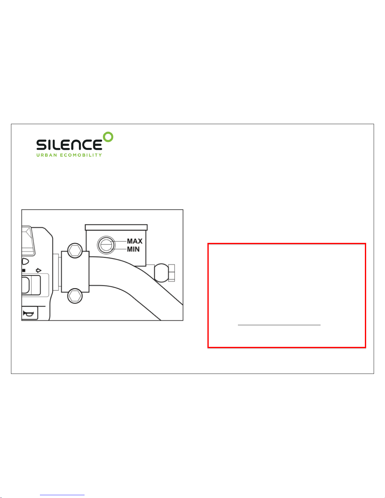
2.5 BRAKE FLUID
The brake fluid reservoir is located on the upper part of the
handlebar. Check the level without stands.
The brake fluid level must not fall below the MIN mark on the
reservoir.
Air might enter the reservoir if it is empty. This may cause
problems to the scooter’s brake system.
The brake fluid should always be checked and replaced at
regular intervals. The front and rear tanks should be kept
topped up above the halfway mark with brake fluid. If the level
is too low, add brake fluid.
2.6 FRONT BRAKE
The brake pads have safety grooves. If the grooves of the
friction material are visible, ask your dealer about the
replacement.
2.7 REAR BRAKE
When the thickness of the rear brake pads is less than 1 mm,
they lose their effectiveness. Ask your dealer about the
replacement of the pads.
WARNING
The brake fluid may damage the motorcycle
paintwork and the plastic parts in the event of
accidental spillage.
The brake fluid may cause damage and injury
if handled incorrectly.
If the brake fluid comes into contact with the
skin, wash immediately with water. If brake
fluid splashes into your eyes, flush with water
and seek medical attention immediately.
Never mix used oil with new oil.
USE DOT4 OIL.

46
2.8 BRAKE LINES
The brake lines should be changed every four years.
2.9 BRAKE LEVER
If there is excessive play in the brake lever but the brake pads are still in good
condition, take the motorcycle to an authorized dealer as soon as possible for
inspection.
After the ready for use icon lights up on your scooter, make sure that the braking
system operates correctly: Pull the left and right brake levers at the same time to
check that both have braking pressure.
Once the scooter ready icon is lit, release the brake levers. The system is enabled
and the throttle is ready to be used.
Scooter ready icon.

47
3. TROUBLESHOOTING
In the faults described below, it is assumed that the final components are the cause of the fault.
If the problem persists after the final component has been replaced, take the motorcycle to an authorised dealer.
All our motorcycles are carefully inspected before delivery to the Dealer. Even after the scooter has been inspected,
some problems may appear. The following table offers a guide for identifying the problem and, if possible, repairing it
yourself.
If you are unable to resolve the problem, take the scooter to the dealer for repair.

48
4. INCORRECT OPERATION MESSAGES
Problem
Cause
Solution
Front lights are not working.
The component is defective or connectors are damaged.
Damaged fuses
Check connectors and replace fuses. If the problem
persists, contact closest authorized dealer.
Back lights or breaking lights do not work.
The component is defective or connectors are damaged.
Damaged fuses
Check connectors and replace fuses. If the problem
persists, contact closest authorized dealer.
Scooter does not speed up.
Throttle is not adjusted properly.
Check the connection between the throttle and electrical
installation.
Contact closest authorized dealer.
Scooter does not start.
Key not inserted. Scooter is charging. Battery is
discharged.
Damaged fuses.
Check if the key is inserted in the groove. Wait until
charging is finished and unplug charger. Charge battery
completely. Replace damaged fuses. If the problem
persists, contact closest authorized dealer.
Battery is not charging, battery percentage
does not increase.
Problem in the battery, problem in the charger.
No electricity in the charger.
Check charger-battery and battery-electrical installation
connections. Check connection of the charger to electric
network.
Breaks do not break properly.
Leakage in the brakes / Low level of fluid in the circuit.
Worn pads.
Check fluid level is correct in tanks. Contact closest
authorized dealer.
Scooter is unstable.
Air pressure is incorrect.
Pneumatics are worn. Compartments are loaded
excessively.
Air pressure must be checked and brought to the
correct level; front 1.5 bar, rear 2.5 bar. Replace the
tires.
Check if the load is excessive. Drive without load.
Error in the status of charge level.
Charge indicator is not synchronized with the actual
status of charge.
Discharge the scooter until green OK LED blinks 7
times and then charge it completely. Go to the dealer if
the problem persists.
Any other problem
Depends on the problem
Contact closest authorized dealer.

49
The engine controller status LED is found on the instrument panel, in green.
If the LED flashes, depending on the number of the flashes, this guide will help you to determine the cause.
The LED may flash while you are riding the scooter.
Flashes
Cause
Explication and solution
2
Side stand mounted
Sequence failure
If the side stand LED remains lit, the stand should be raised.
While the scooter accelerates, it moves suddenly forwards or backwards. Switch off
and back on.
Switch on the motorcycle while the throttle is open. Switch off and switch back on
without accelerating.
7
Battery discharged
The battery energy is running out.
Power is reduced.
Return as soon as possible to charge the vehicle.
8
Temperature too high
Allow scooter to cool. To lower the temperature, continue riding without using the
regenerative brake.

50
5. CLEANING AND STORAGE
All the parts of the scooter have the same risk of corrosion due to the aggressive contaminants in the atmosphere and the
effects of the salt on the road. The user is responsible for adequately protecting the motorcycle from these factors. This guide
favours the maintenance of the vehicle, maintains its value and prevents any warranty claim.
5.1 CLEANING
Clean the scooter at regular intervals. As with any vehicle,
it is important to wash it at regular intervals to keep it in
good condition.
NOTE
DO NOT USE A HIGH PRESSURE JET CLEANER.
Never use abrasive detergents on the scooter.
Try to find gentle cleaning products for the vehicle
which are environmentally-friendly.
NOTE
Always use a clean cloth to dry the scooter. Dirty cloths
may scratch smooth and shiny surfaces and clean cloths
help to minimise scratches.
Never use hard cloths or anti-insect sponges
to remove insects from the screen.
5.2.- STORAGE
If the scooter is to be left unused for extended periods, you
should read and follow the procedures below:
1 -. Wash the scooter and allow it to dry before storage.
2 -. Mount the scooter on the main stand.
3 -. Check the scooter for any past problems.
4 -. A cover helps to protect the motorcycle from the elements
and is a good investment.
5 -. Place a protective sheet on the ground to protect it from
possible leaks and to prevent faults.
NOTE
Always allow the scooter to dry completely prior to use.
Traces of water may lead to problems of contact in the
electronic components.
WARNING
Do not clean the battery with too much
water or a high pressure jet.

51
VEHICLE AND BATTERY WARRANTIES

52
MAINTENANCE PROGRAM
1. DELIVERY TO THE BUYER
2. WARRANTY CONDITIONS
3. INSPECTIONS

53
1.- DELIVERY TO THE BUYER
This document is the basis for any warranty applications.
Warranty applications cannot be processed if the documents have not been completed correctly.
VIN (vehicle identification number)
Full name…………………………………….
Street…………………………………………………….
City………………………………………………….
Post code…………………………………………
Country……………………………………………………..
Telephone / Mobile
phone………………………………………
e-mail…………………………………………………..
……………………………………..
Date of delivery
Name of Dealer
Establishment stamp

54
2.- WARRANTY CONDITIONS
This vehicle is guaranteed for 2 years, from the date of
delivery and receipt, against any defect in the design or
manufacturing, both for the engine and for the battery and
control system.
Fast-wearing parts, including the glass panels, lamp bulbs, tyres,
brake discs, brake pads, are not included in the warranty. The
manufacturer and the appointed workshop shall decide which
defective parts are to be replaced or repaired.
The right to warranty shall not exist if:
a) The end user has treated the vehicle contrary to the
regulations.
b) The end user has carried out any of the inspections
stipulated in the service log or any repairs at a workshop not
authorised by the manufacturer.
c) The vehicle has been modified or changed in any way or
fitted with parts that do not form part of the vehicle equipment
which has been expressly certified by the manufacturer.
d) The vehicle has been used in a sports competition.
e) The operation, maintenance and service instructions
established in this manual have not been observed.
f) Warning: Regular Use. At least once a week, running for at
least 10 hours.
Without Regular Use. The scooter must be fully charged
before leaving it stationary for periods longer than 1 week.
The scooter should be charged at least once every 30 days,
and run for at least 24 hours.
Agreements which differ from the above warranty conditions
shall be confirmed in writing by the manufacturer.

55
3.- INSPECTIONS
The Authorised Dealer should offer advice and a comprehensive service to keep your scooter in optimum conditions.
Here are some tips for simple procedures in the event that an inspection or repair is necessary.
1 -. Only have the scooter serviced by an authorised workshop.
2 -. Make an appointment with the workshop foreman.
3 -. Explain the problem, or make a list.
4 -. If something is not clear, please talk to the workshop foreman.
5 -. Give clear instructions.
6 -. Ask for the cost estimate before the work starts.
7 -. Leave your phone number so that the workshop manager can phone you should any important questions arise.
8 -. Establish a price limit for any additional work required.
9 -. Talk openly about complicated matters with your dealer.
10 -. Observe the regular service inspections of the scooter.
FIRST INSPECTION - 1500 Km.
This official service inspection must take place no later than 1 year after the date of delivery.
It is important that the steering is retightened during the first service, otherwise the vehicle will no longer be under warranty.
Failure to perform the first service inspection may result in the loss of cover under warranty.

56
Service inspections must be carried out within 100 km of the due date, and no later than 1 year after the last service. The screen
displays the kilometres remaining until the next service.
1.500 km
Date………………..
Km…………………
…………………………
Signature of the Authorised
Service
5.000 km
Date………………..
Km………………....
…………………………
Signature of the Authorised
Service
10.000 km
Date………………..
Km………………….
…………………………
Signature of the Authorised
Service
15.000 km
Date………………..
Km………………....
…………………………
Signature of the Authorised
Service
20.000 km
Date………………..
Km………………....
…………………………
Signature of the Authorised
Service
25.000 km
Date………………..
Km………………….
…………………………
Signature of the Authorised
Service

57
30.000 km
Date………………..
Km………………....
…………………………
Signature of the Authorised
Service
35.000 km
Date………………..
Km…………….…...
…………………………
Signature of the Authorised
Service
40.000 km
Date………………..
Km…………….…...
…………………………
Signature of the Authorised
Service
45.000 km
Date………………..
Km…………………
…………………………
Signature of the Authorised
Service
50.000 km
Date………………..
Km…………………
…………………………
Signature of the Authorised
Service
55.000 km
Date………………..
Km………………….
…………………………
Signature of the Authorised
Service
 Loading...