

Page 1
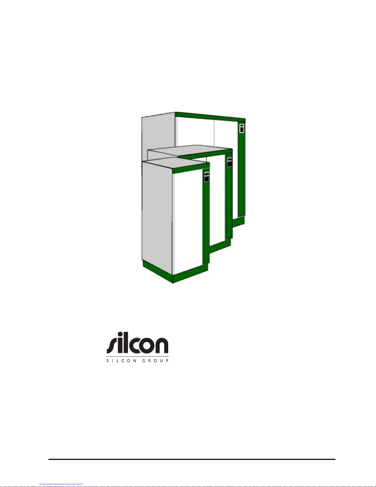
1User Guide DP300E
7OA0001 GB rev.09
DATAPOWER™
DP300E Series
User guide
Copyright © 1997 Silcon Power Electronics A/S
Due to continuous product development information given in this
manual is subject to change without notice.
Page 2

2 User Guide DP300E
7OA0001 GB rev.09
Page 3

3User Guide DP300E
7OA0001 GB rev.09
Contents:
1.0 Introduction
1.1 General
1.2 The display unit
2.0 Stop-start
2.1 General
2.2 Stop
2.3 Start
3.0 Operation
3.1 Keyboard description
4.0 Programming parameters
4.1 General
4.2 Parameters
5.0 Reading out measurements
6.0 Alarms - what to do
6.1 General
6.2 The events stack
6.3 Alarm messages
6.4 The events logger
6.5 Displaying the events stack
7.0 Service bypass switch
7.1 Operating the external service bypass switch
7.2 Operating the external service bypass switch
for parallel systems
8.0 Preventive maintenance
8.1 General
8.2 Fan
8.3 Battery
8.4 Battery capacity test
9.0 Economy operation
10.0 Software
10.1 Choice of software
10.2 Configuration codes
10.3 Choice of cable
11.0 How to contact Silcon
Page 4
4 User Guide DP300E
7OA0001 GB rev.09
Introduction
1.0 Introduction
1.1 General
Congratulations on your choice of UPS (Uninterruptible Power Supply).
This UPS has been designed and produced for reliable and troublefree long-term
use.
For you it means that once installed and commissioned, you can forget it. You only
have to arrange a preventive maintenance as described in section 8 of this manual.
1.2 The display unit
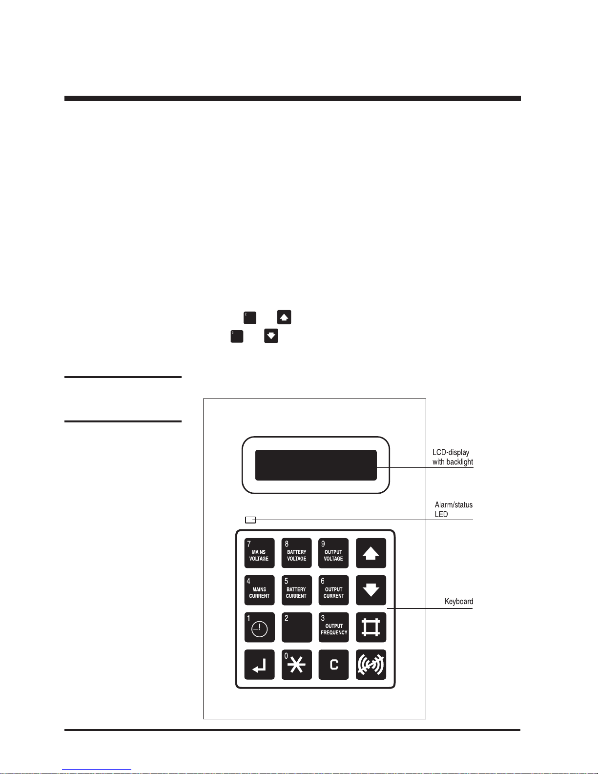
The display unit – placed on the front of the UPS – is the link between user and
UPS.
It consists of a display, an alarm LED, and a keyboard.
The display is used for showing parameters, measured values, and alarm messages. A background light is activated in case of an alarm or if one of the keys are
pressed. No activity or no alarm for 5 minutes will automatically switch of the
light.
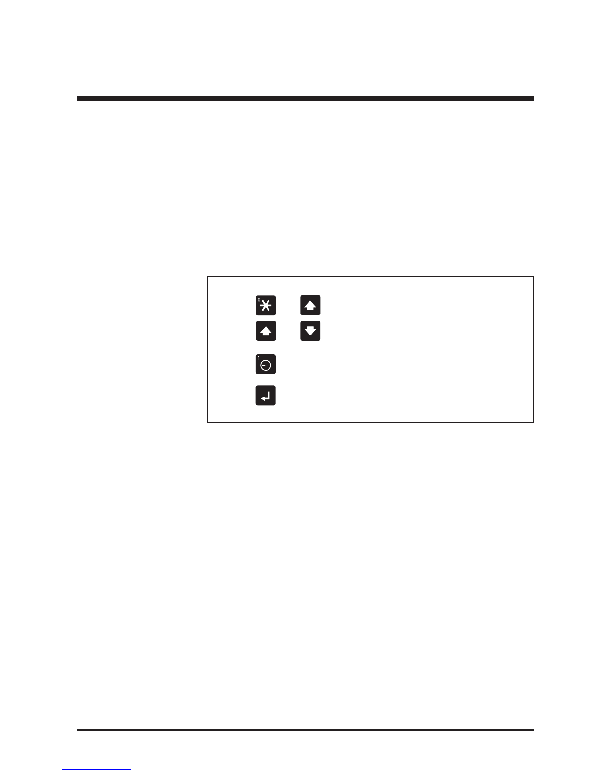
By pressing and simultaneously you increase the contrast, and by
pressing and simultaneously you decrease the contrast.
The alarm LED is together with an acoustic signal the indicator for unusual
operating situations. The light changes from green to red in case of alarm. The
keyboard is used for programming of operating parameters and for calling readouts of parameters / alarm messages.
Note:
The display accuracy is
±1%, ± 1 digit.
Page 5
5User Guide DP300E
7OA0001 GB rev.09
2.0 Stop – start
2.1 General
According to electrical regulations only the local authorized electrical installer is
normally allowed to perform a complete switching in and out of the UPS, as it
involves operation of the battery supply breaker, where touch of high voltage parts
is possible.
For above reasons the normal user can only switch the UPS into system off mode
and from here back into normal operation via the “safe” push buttons.
2.2 Stop
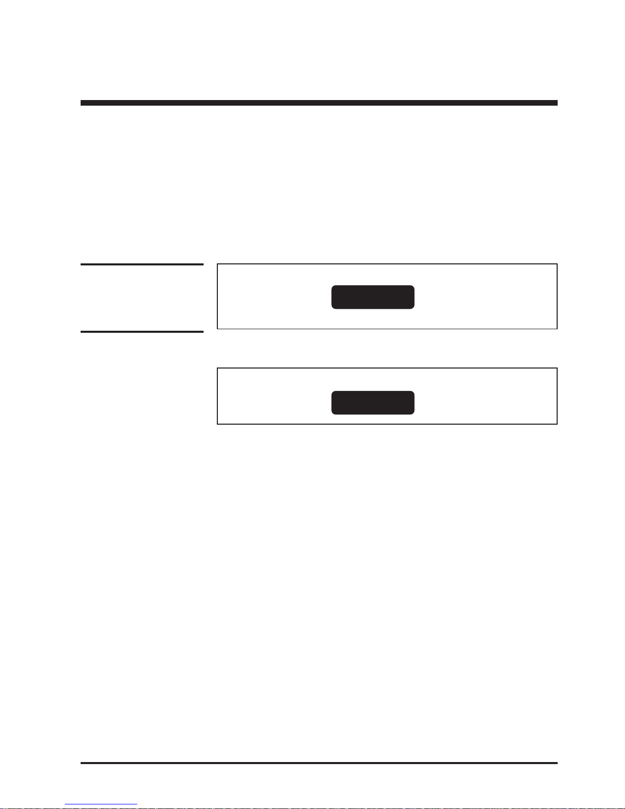
Action Display shows Description
Open the front door
and activate the ”ON”
and “OFF” push-button
simultaneously
2.3 Start
Action Display shows
Open the front door and
activate the green “ON”
push-button
Stop – start
System off
Alarm LED lights. Acoustic
alarm sounds for 30 seconds.
Warning:
Please read maintenance
section, if UPS has to be
stopped for more than one
week.
Normal operation
Load power xx%
Page 6
6 User Guide DP300E
7OA0001 GB rev.09
Operation
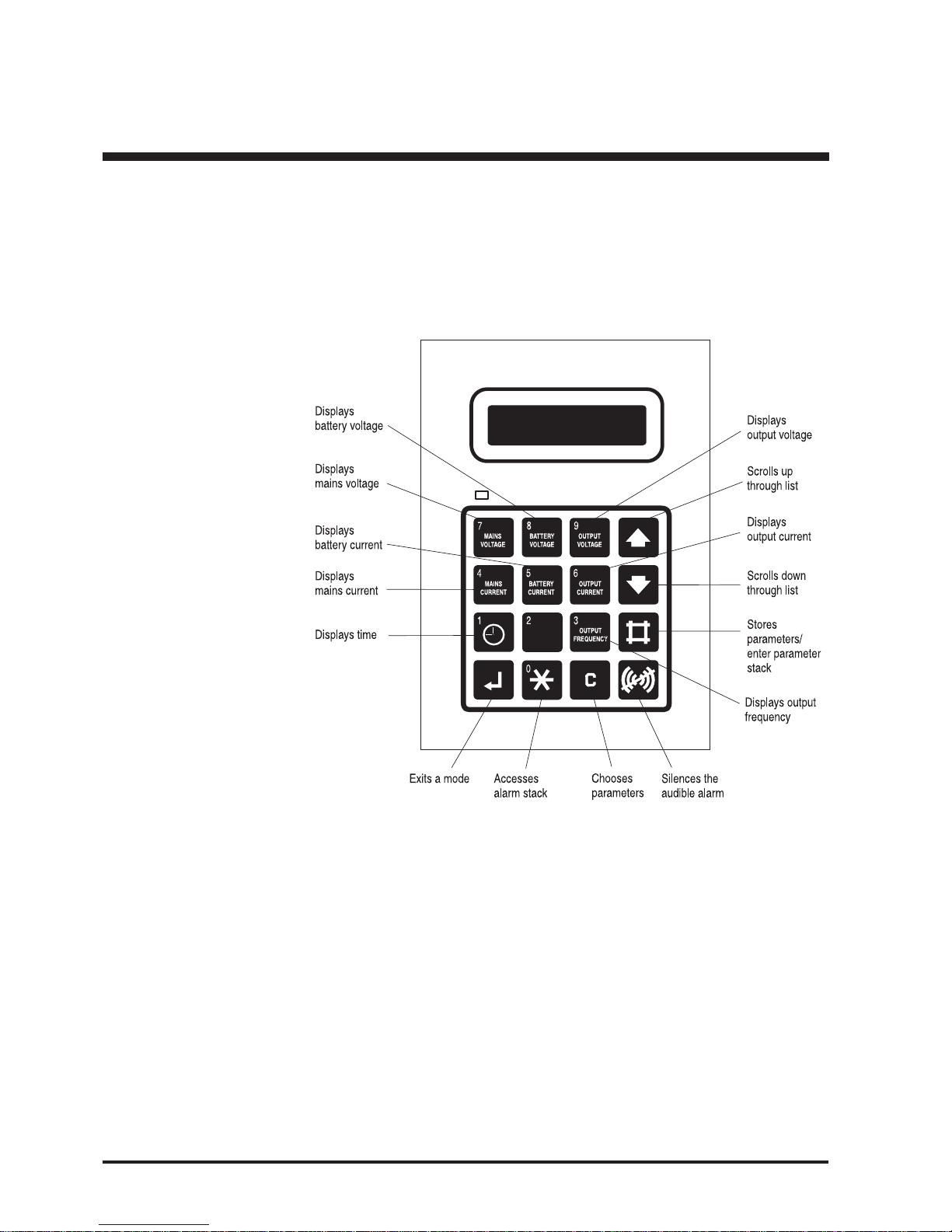
3.0 Operation
The display is used to show parameters, alarms/messages, and measured values.
The alarm LED is used with an audible alarm to indicate unusual operating
situations. The keyboard is used for programming and control of displaying parameters, alarm messages, and displaying measured values.
3.1 Keyboard description
Page 7
7User Guide DP300E
7OA0001 GB rev.09
Programming parameters
NOTE:
The system must not run in
bypass mode for longer
periods of time as the
batteries will not be recharged
4.0 Programming parameters
4.1 General
Some operating parameters can be programmed directly from the keyboard, but
this has already been done during the commissioning. Unless you are quite sure of
the consequence of changing the following parameters, then let it be a task for your
local dealer, if needed.
Parameters are programmed as shown in the example 4.2.3.
4.2 Parameters
4.2.1
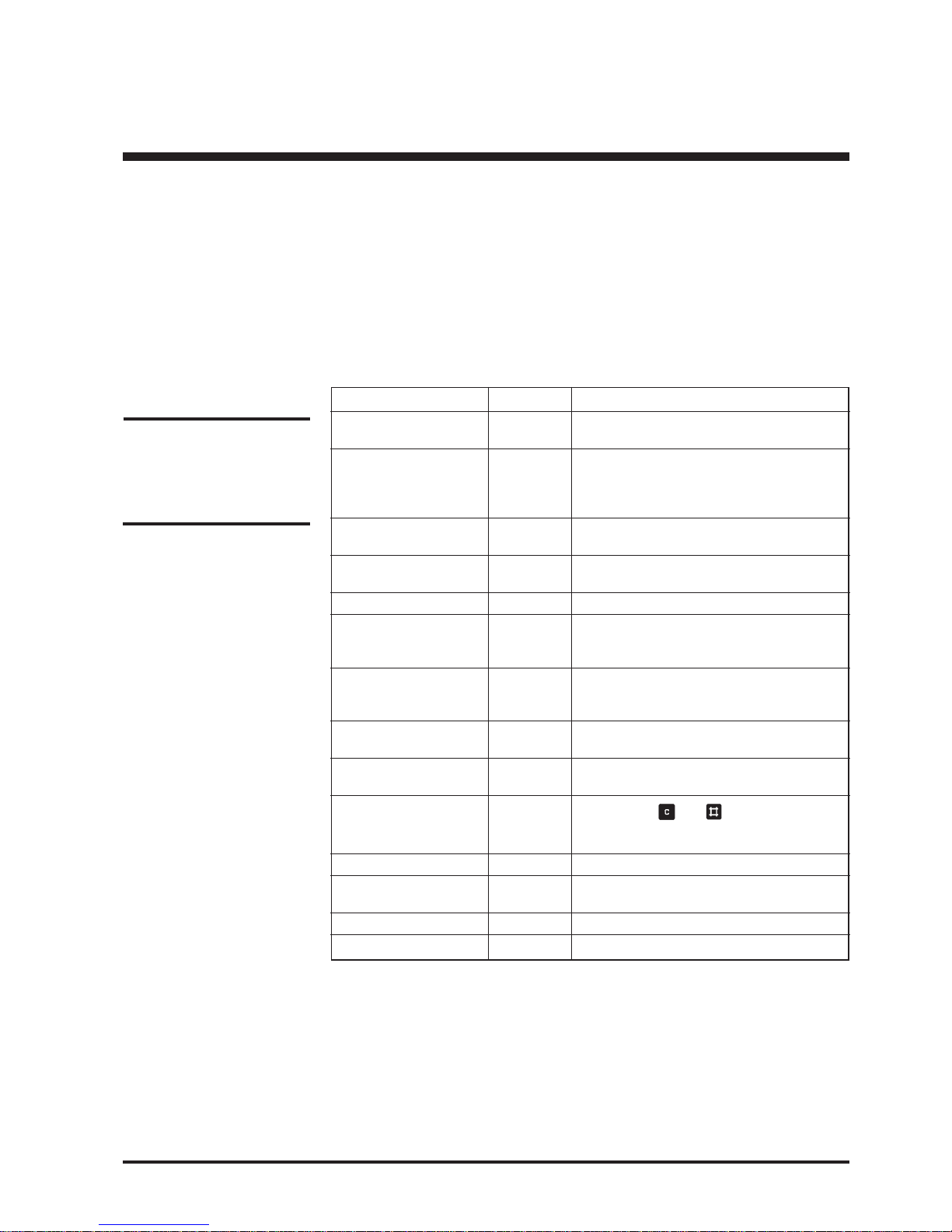
Parameter Setting* Comments
Bypass YES, NO “YES” will switch the system into
bypass mode
Language GB, D, F, Language of text in display
DK, S, SF
NL, PL, CZ
E, P, SK, H
Autostart YES, NO Automatic restart by mains return.
Ensures quick battery recharge.
Remote shutdown YES, NO Shutdown of UPS by remote signal
active
Remote shutdown HIGH, LOW Nature of remote shutdown signal polarity
Remote shutdown time 0, 1, 2, 3, 4 Time delay on remote shutdown of UPS
5, 6, 7, 8, 9
10 min.
Battery capacity test - Initiates check of back-up time. The
measured time is from start until it reaches
low DC warning level (See section 8.4)
Battery monitor test** - Initiates check of battery condition by
25% discharging.
Automatic battery test** NO, 3, 6 Activates the battery monitor test in cyclic
intervals (Unit - months)
Battery monitor reset** - Pressing the
and key after
selecting this parameter resets alarms
and flushes messages in the alarm stack
Boost charge YES, NO “YES” results in boost charge (10 hours)
Autoboost charge YES, NO “YES” results in boost charge after battery
operation (10 hours)
Enter new date YYMMDD Local date can be entered
Enter new time HHMMSS Local time can be entered
* Text in bold letters are the standard setting
** Only for systems with Battery Monitor active
Page 8
8 User Guide DP300E
7OA0001 GB rev.09
Programming parameters
To return to normal operation
Action Display shows
5. Press
to enter parameter stack
6. Press
or until
7. Press
until
8. Press to store
9. Press to exit
Programming of the other parameters can be performed in exactly the same way.
Bypass operation
: YES
Normal operation
load power xx%
Bypass operation
: NO
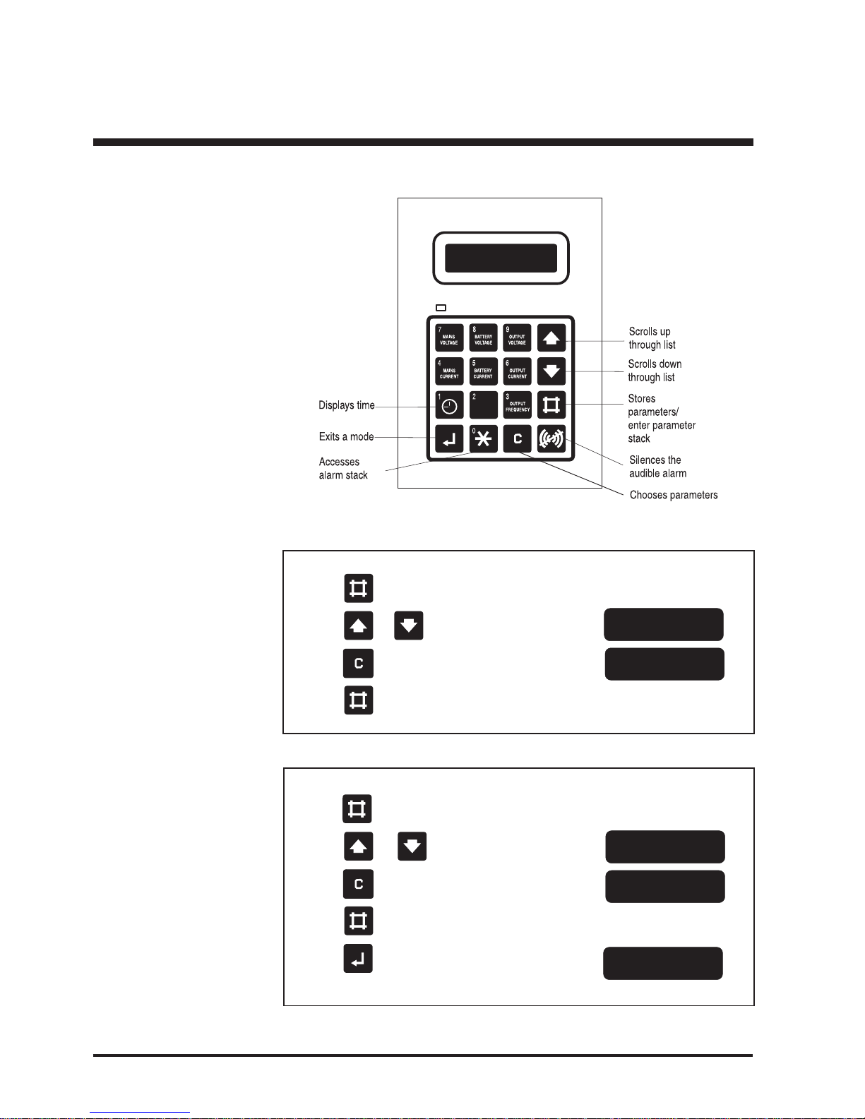
4.2.2 Keys used for programming
4.2.3 Programming example - switch to bypass operation
Action Display shows
1. Press to enter parameter stack
2. Press or until
3. Press
until
4. Press to store
Bypass operation
: NO
Bypass operation
: YES
Page 9
9User Guide DP300E
7OA0001 GB rev.09
Measurements
5.0 Reading out measurements
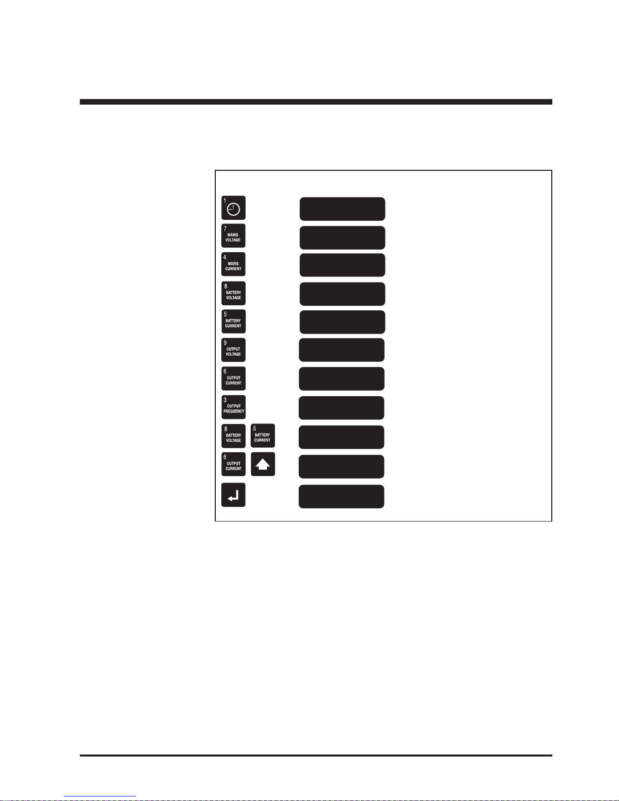
Press as indicated below one key or two keys simultaneously (Used values are only
random for illustration):
Action Display shows Description
96.04.16
10.22,13
Mains voltage
385 385 385 V
ac
Battery current
+ 2 A
dc
Mains Current
16 16 16 A
ac
Battery voltage
438 437 V
dc
Year, month, day
Hour, minute, second
Mains voltage
is 3 x 385 V
ac
Mains current
is 3 x 16 A
ac
Battery voltage is 438 V
dc
on batt.1.
437 Vdc on batt.2.
Charging current is (+) 2 A
dc
(Discharging current (÷))
Output voltage
is 3 x 380 V
ac
Output current
is 3 x 15 A
ac
Output frequency
is 50 Hz
Battery temperature
is 25°C
Output peak current is 3 x 22A
ac
(only of interest for service engineers)
Returns to normal status indication.
If not pressed, automatic switch back
will be performed after 20 seconds.
Output voltage
380 380 380 V
ac
Output current
15 15 15 A
ac
Output frequency
50Hz
Battery temp.
25ºC
Output peak current
22 22 22 A
ac
Normal operation
load power xx%
Page 10
10 User Guide DP300E
7OA0001 GB rev.09
NOTE:
A battery monitor test can
not be performed unless the
battery is fully charged.
6.0 Alarms - What to do
6.1 General
Alarms are indicated by the red lamp (above the upper left corner of the keyboard)
and by a 30 secs. acoustic signal. An alarm is registered in an alarm stack as long as
it is present, and if more in the same succession as they arise.
6.2 The alarm stack
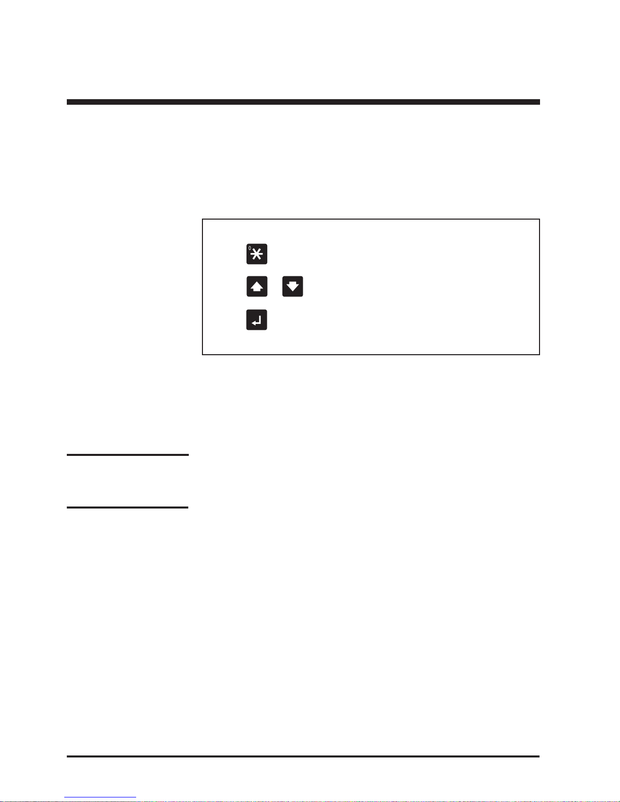
The alarm stack can be displayed by:
Action Description
1. Press
Access to the alarm stack
2. Press
or Scroll up or down through the alarm stack messages.
Last message is “No (further) alarm”.
3. Press
Exits the alarm stack. If not operated the system
will exit the alarm stack automatically
after 30 seconds.
6.3 Alarm messages
The alarm messages are together with the events logger (described in section 7.0)
part of a diagnostic system for the UPS service specialist.
Before calling for assistance you may take one or more of the following actions.
1. “Battery defective” means no back-up capacity any longer. Call for assistance.
“Battery Week” means reduced back-up capacity. Reset the “Battery week” alarm
signal according to point 4.2 and start up a battery capacity test according to
point 8.4. When finished – record the obtained back-up time and reset an
eventual new alarm from the battery monitor. Let the UPS recharge the battery
for at least 16 hours, and with the same load as before start up a second battery
capacity test. If this results in improved back-up time continue with further
capacity tests until none or insignificant improvements take place. Above might
“wake up” the battery – else call for assistance.
2. Check the local mains power supply. One or more fuses may be blown or somebody could by accident have switched off the supply.
3. Check if the cooling air intake on your UPS has been blocked.
4. Check if somebody has switched more load on the UPS - the max. output capacity may be exceeded.
5. If there is no output voltage from the UPS - the mains supply is present and
atempt to restart gives no result – bypass the UPS as described in the following
section by means of the external service bypass switch if present.
Alarms
Page 11
11User Guide DP300E
7OA0001 GB rev.09
6.4 The events logger
The events logger is a memory stack, in which the last 250 events are stored in the
same succession as they arose. (Showing the latest at first).
Events stored are the alarms and the following operational modes:
Mode Comments
MPU is reset UPS has been totally switched off
Stand-by UPS has been in stand-by mode by parallel
system
Normal operation UPS has been in normal operation
Battery operation UPS has been in battery operation
Bypass operation UPS has been in bypass operation
System off UPS has been off
6.5 Displaying the events stack
Action Description
1. Press
and
2. Press or
3. Press
4. Press
Alarms
Press the two keys simultaneously to get
access to the events stack
Scroll up or down through the events stack
(last message is “No (further) event”).
Displays the time where the event happened
Exit the events stack. If not operated the
system will exit the events stack automatically
after 30 seconds
Page 12
12 User Guide DP300E
7OA0001 GB rev.09
Warning:
If the UPS is out of service
for more than 8 days the
connected batteries might
be damaged. Refer to total
„Switching off“ as described
in the Installation Guide.
Service Bypass Switch
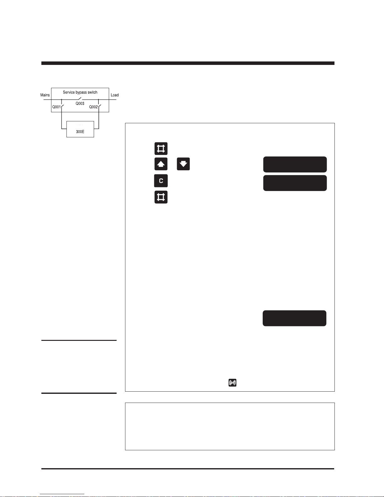
7.1 Operating the external service bypass switch
7.1.1 Bypassing the UPS
Action
1. Press on the keyboard
2. Press
or on the keyboard until
3. Press
on the keyboard
4. Press on the keyboard
5. Check lamp indication on the bypass panel The Green lamp (H003)
above the bypass switch
handle (Q003) lights
6. Turn the external bypass switch (Q003) The Green lamp (H002)
to position „1“. above the output switch
handle (Q002) lights
7. Turn the output switch (Q002) to Only the lamp (H002) above
position “0”. the output switch handle
(Q002) lights now
8. Open the front door and press both the green
„ON“ and the red „OFF“ key simultaneously
The acoustic alarm sounds for 30 secs.*
9. Turn the input switch to position „0“.
The red alarm LED below the display lights and
the acoustic alarm sounds for 30 secs.
* The acoustic alarm can be reset by the key
EMERGENCY (UPS not alive)
1. Turn the input switch (Q001) to position „0“.
2. Turn the output switch (Q002) to position „0“.
3. Change released system input fuse(s), if any.
4. Turn the bypass switch (Q003) to position „1“.
Bypass operation
: NO
Bypass operation
: YES
**System OFF**
Display shows
Lamp indication on
bypass panel
Display shows
7.0 Service bypass switch
DP
Page 13
13User Guide DP300E
7OA0001 GB rev.09
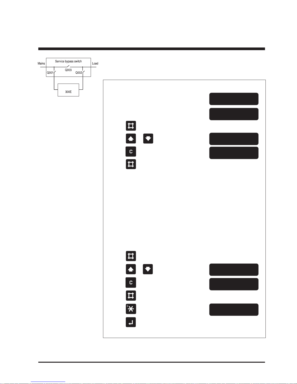
7.1.2 Switching the system from external bypass into normal
UPS operation
Action*
1. Turn the input switch (Q001) to position
„1“
2. Open the UPS front door and press the
green „ON“ key
3. Press
on the keyboard
4. Press or on the keyboard until
5. Press on the keyboard
6. Press
on the keyboard
7. Check lamp indication on the bypass panel The Green lamp (H002)
above the output switch
handle (Q002) lights
8. Turn the output switch (Q002) to position Now the green lamp (H003)
„1“ above the bypass switch
handle (Q003) lights too
9. Turn the bypass switch (Q003) to position Only the green lamp (H003)
„0“ above the bypass switch
handle (Q003) lights
10. Press
on the keyboard
11. Press
or on the keyboard until
12. Press
on the keyboard
13. Press on the keyboard
14. Press
on the keyboard
15. Press
on the keyboard
**System OFF**
Normal operation
load power 0%
Lamp indication
on bypass panel
Display shows
Bypass operation
: YES
Bypass operation
: NO
Bypass operation
: YES
Bypass operation
: NO
Normal operation
load power xx%
No lamps on the bypass
panel light any longer
Display shows
Service Bypass Switch
DP
Page 14
14 User Guide DP300E
7OA0001 GB rev.09
Service Bypass Switch
Bypass operation
: NO
Bypass operation
: YES
**System OFF**
Display shows
Display shows
Warning:
If the UPS is out of service for
more than 8 days the
connected batteries might be
damaged. Refer to total
„Switching off“ as described in
Instal. Guide Chapter 7.0.
Lamp indication
on bypass panel
Bypass operation
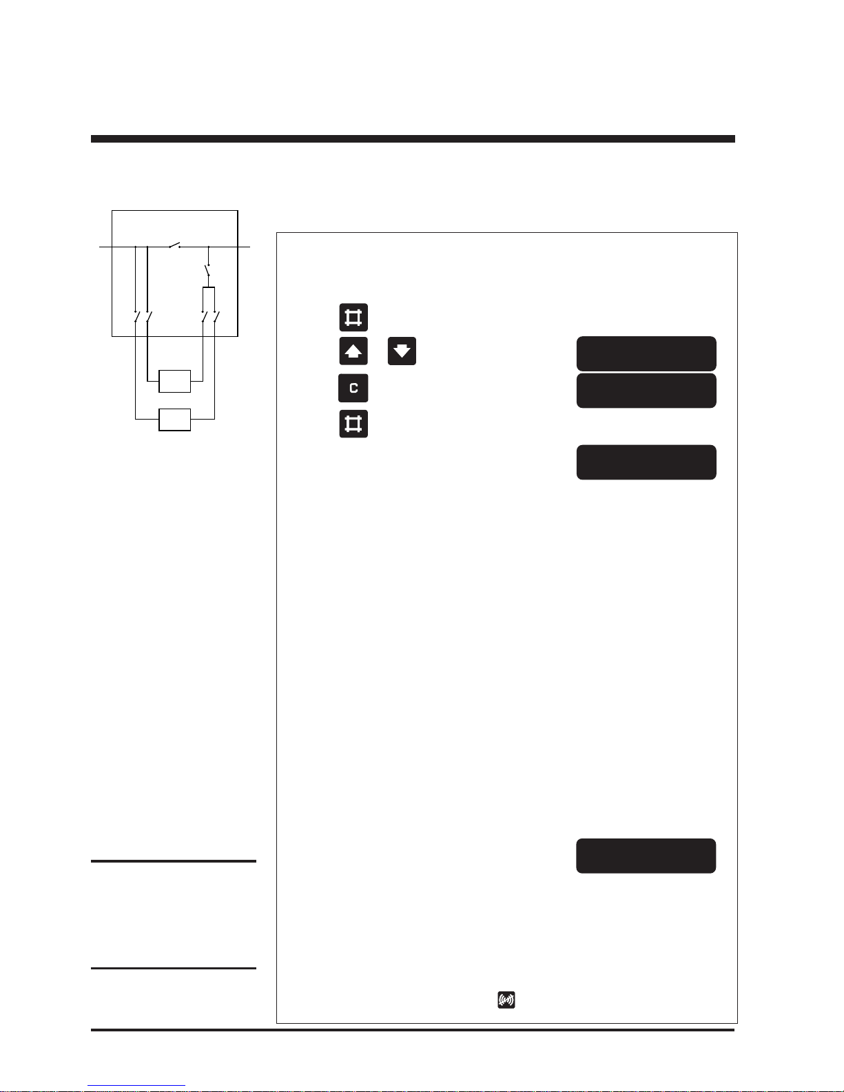
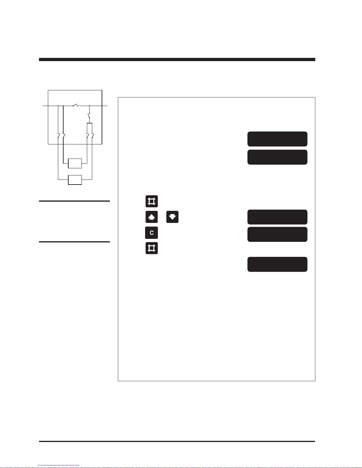
7.2.1 Bypassing the parallel UPS system
Action
Point 1-4 can be carried out with any of the parallel systems, however this will switch all
systems into bypass operation.
1. Press
on the keyboard
2. Press or on the keyboard until
3. Press on the keyboard
4. Press
on the keyboard
All systems will transfer to bypass operation
Do not switch off any of the UPS systems until
point 5-8 has been carried out
5. Check lamp indication on the bypass panel The green lamp (H003)
above the bypass switch
handle (Q003) lights
6. Turn the external bypass switch (Q003) The green lamp (H004)
to position „1“ above the output isolator
(Q004) and the green lamps
(H002) above the output
switch handles (Q002) light
7. Turn the output isolator (Q004) to position “0” The green lamp (H002)
above the output isolator
light
8. Turn all output switches (Q002) to position „0“ Only the lamp (H002) above
the output switch handles
(Q002) lights now
9. Open the front door and press both the green
„ON“ and the red „OFF“ key simultaneously
in any of the systems
The acoustic alarm sounds for 30 secs.*
Repeat for (all) other system(s).
10. Turn all input switches (Q001) to position „0“
The red alarm LED below the display lights and
the acoustic alarm sounds for 30 secs.
* The acoustic alarm can be reset by the key
7.2 Operating the external service bypass switch for parallel
systems
DP300E
DP300E
Q003
Q001a
Q001b
Q002b
Q004
Q002a
Service Bypass Switch
LoadMains
Page 15

15User Guide DP300E
7OA0001 GB rev.09
Service Bypass Switch
EMERGENCY (UPS not alive)
1. Turn the input switches (Q001) to position „0“.
2. Turn the output switches (Q002) to position „0“.
3. Turn the output isolator (Q004) to position “0”.
4. Change possible released system input fuse(s).
5. Turn the bypass switch (Q003) to position „1“.
Page 16
16 User Guide DP300E
7OA0001 GB rev.09
Service Bypass Switch
7.2.2 Switching the parallel system from external bypass into normal
UPS operation
Action
1. Check that output isolator (Q004) is in
position “0”
2. Turn input switches (Q001) and output
switches (Q002) to position “1”
3. Open the UPS front door and press the
green “ON” key on all systems
Point 4-7 can be carried out with any of
the parallel systems, however this will
switch all systems to bypass operation
4. Press
on the keyboard
5. Press or on the keyboard until
6. Press
on the keyboard
7. Press on the keyboard
All systems will transfer to bypass operation
8. Check that green lamp (H004) above output
isolator (Q004) lights
9. Turn the output isolator (Q004) to position “1” Now also the green lamp
(H003) above the bypass
switch handle (Q003) lights
10. Turn the bypass switch (Q003) to position „0“ Only the green lamp (H003)
above the bypass switch
handle (Q003) lights
Point 11-16 must be carried out with same
UPS as was used for point 4-7
**System OFF**
Normal operation
load power 0%
Display shows
Lamp indication
on bypass panel
Bypass operation
: YES
Bypass operation
: NO
Note:
If battery has been disconnected please refer to
“Starting Up” in Instal. Guide
Chapter 5.0 to connect
battery(-ies) again.
Bypass operation
DP300E
DP300E
Q003
Q001a
Q001b
Q002b
Q004
Q002a
Service Bypass Switch
LoadMains
Page 17
17User Guide DP300E
7OA0001 GB rev.09
Service Bypass Switch
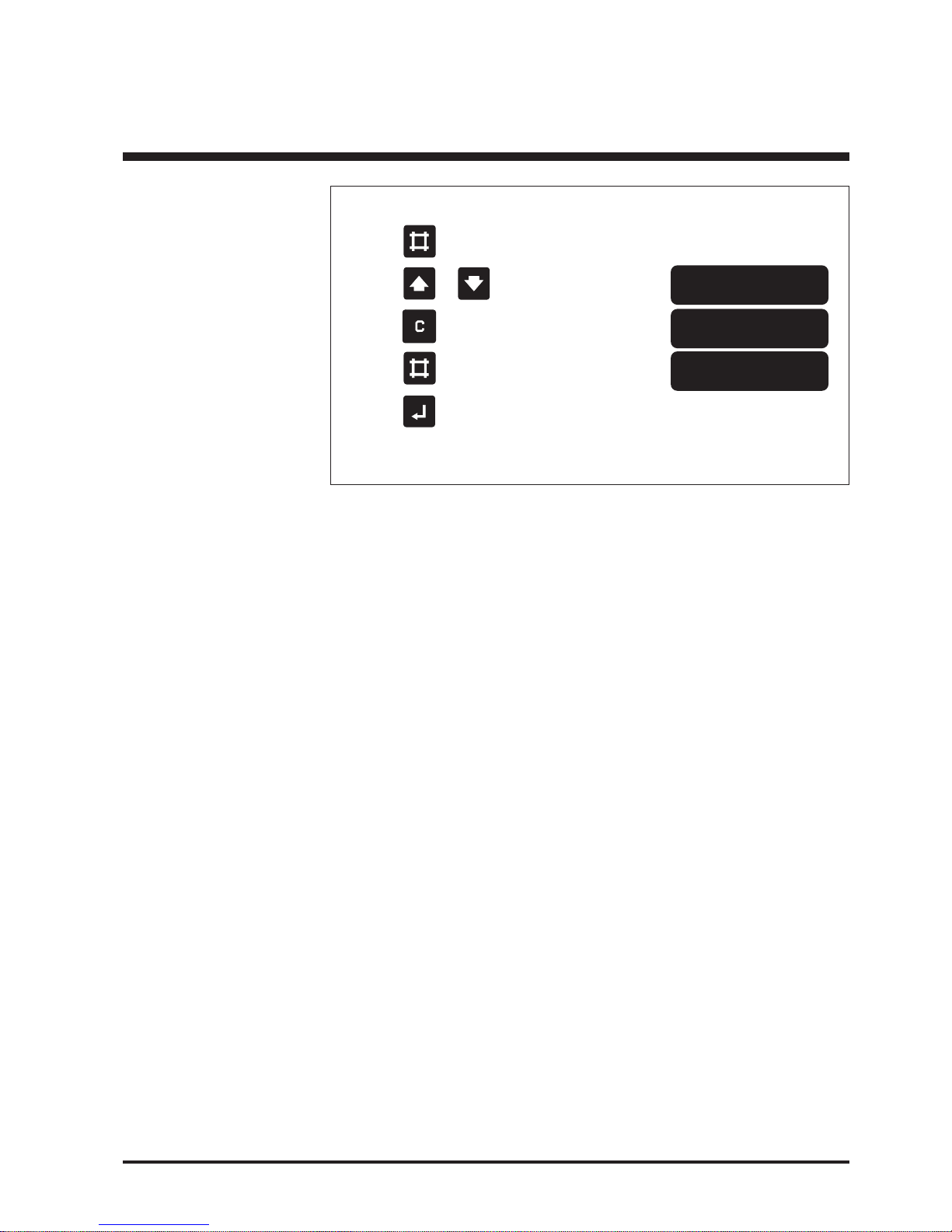
11. Press on the keyboard
12. Press
or on the keyboard until
13. Press
on the keyboard
14. Press on the keyboard
15. Press on the keyboard
No lamps on the bypass
panel lights any longer
Bypass operation
: YES
Bypass operation
: NO
Normal operation
load power xx%
Display shows
Page 18
18 User Guide DP300E
7OA0001 GB rev.09
Service Bypass Switch
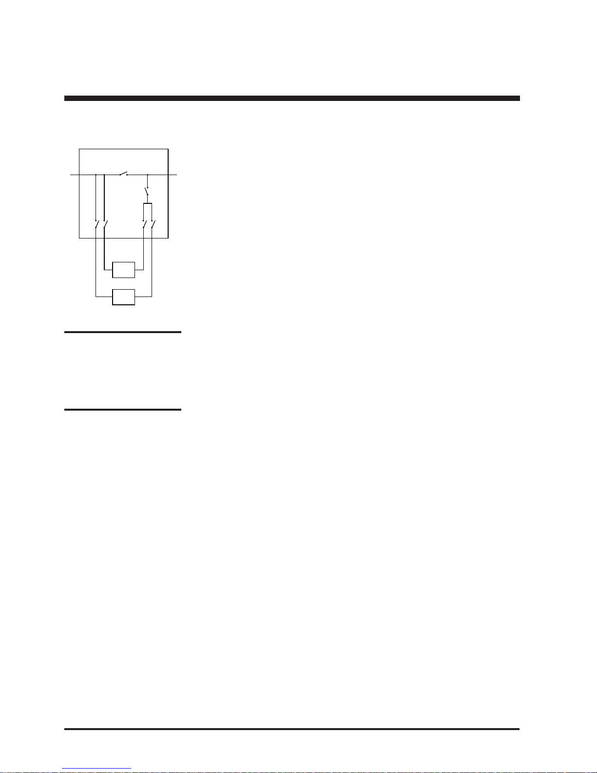
7.2.3 Isolating one UPS for service/maintenance
In a redundant system one UPS can be isolated for service/maintenance without
affecting the other parallel UPS(s).
1. Check that the remaining UPS(s) will be able to carry the load when one UPS is
isolated.
2. Switch off the system to be isolated for maintenance by pushing both the green
“ON” and the red “OFF” key simultaneously.
3. Disconnect battery, mains, and output by opening battery MCCB/fuse and
turning input switch (Q001) and output switch (Q002) to position “0”.
When Q002 is in position “0” the UPS can be operated and tested as a single
system without affecting the other parallel UPS(s).
Switching back the UPS to normal parallel/redundant operation
1. Turn the input switch (Q001) and the output switch (Q002) to position “1”.
2. Charge capacitors, connect battery and start up the UPS as described in chapter
5.0.
The UPS will automatically switch to normal operation and start load sharing
with the other parallelled UPS(s).
Warning!
The system will discharge builtin capacitors. However, before
working on the system check
with a multimeter that there is
no dangerous voltage on the
terminals .
DP300E
DP300E
Q003
Q001a
Q001b
Q002b
Q004
Q002a
Service Bypass Switch
LoadMains
Page 19

19User Guide DP300E
7OA0001 GB rev.09
8.0 Preventive maintenance
8.1 General
The maintenance of the UPS systems should be carried out by trained service
engineers. We recommend that you sign a service and maintenance contract.
8.2 Fan
It is recommended to replace the fans every 3rd year.
8.3 Battery
Systems with built-in batteries have as standard a battery monitoring feature
(option in other systems).
Every time automatic cyclic or manual check is activated, the condition of the
battery is checked. The result is one of following:
1. Battery is OK - nothing will happen
2. Battery has reduced capacity - “Battery week” is given
3. Battery capacity far to low - “Battery defective” is given
The battery monitoring test is performed by taking out max. 25% of the energy in
the battery. But if the battery monitor is not installed or the exact present back-up
time has to be checked, a battery capacity test (8.4) is recommended at least every
sixth month.
For safety reasons battery tests should preferably be made during uncritical periods
for the loads connected.
Test the battery capacity / condition from the keyboard as follows:
Preventive maintenance
Page 20
20 User Guide DP300E
7OA0001 GB rev.09
Warning:
The UPS must at least be in
operation for min. 16 hours
in a 3 month period to
ensure that the battery is
sufficiently charged. If not
the battery might be damaged.
Preventive maintenance
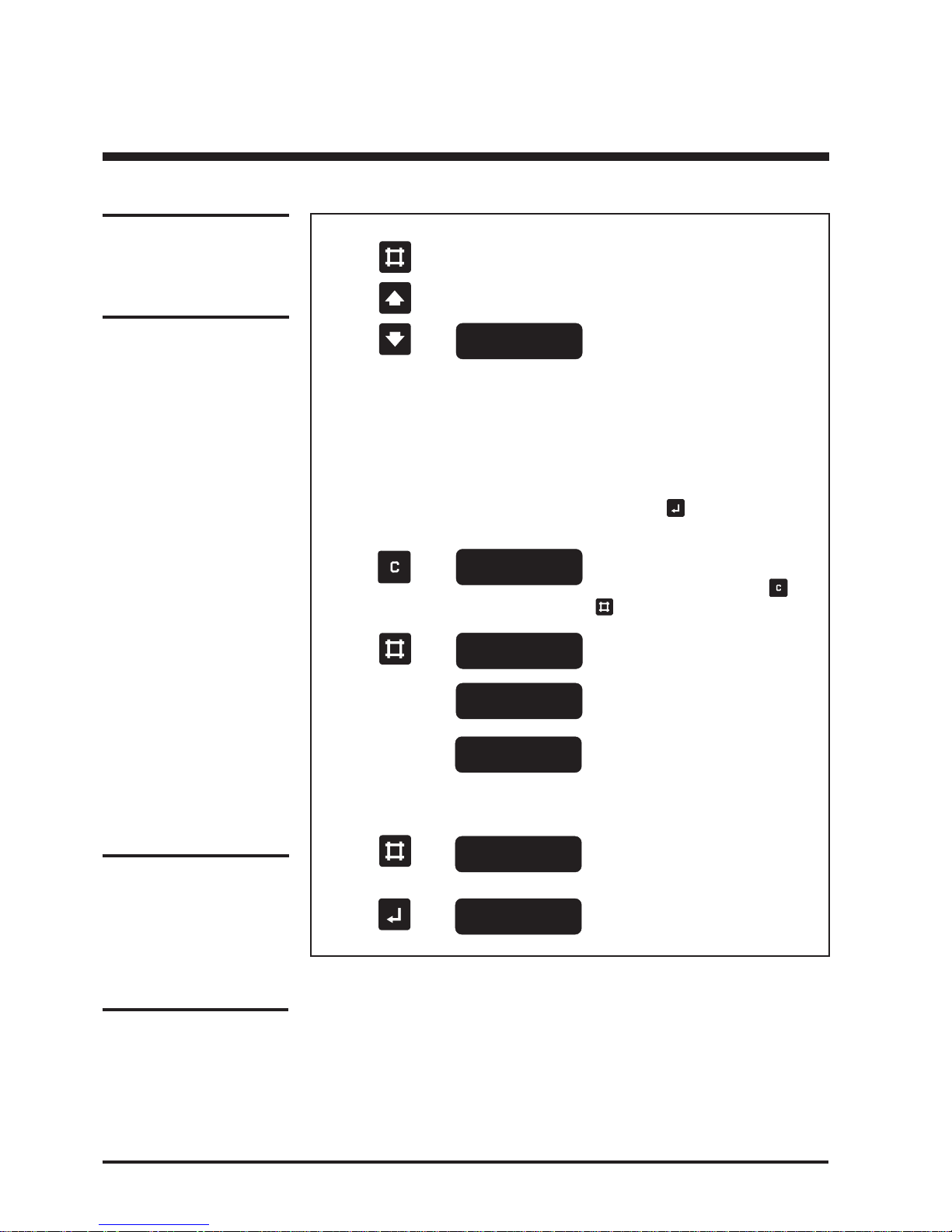
Actions Display shows Description
1. Press
2. Press or
until
3. Press
4. Press
5. Wait about 1 sec.
6. Wait until backup
times expires and
a short alarm
sounds. (No alarm
in battery monitor
test if battery is OK)
7. Press
8. Press
If the UPS has to be taken out of operation for a period of time it is recommended
to disconnect the battery in order to prevent it from being totally discharged. The
information how to do this can be found in the installation guide.
Battery capacity
test : xxx
Starts the battery test.
(To interrupt a r unning test – perform
point 1-2 and then press key and
)
“xxx” is actual obtained back-up time
in minutes. (Battery capacity test
only).
Exits the battery capacity test.
If not operated the system will automatically exit this program after 30
seconds.
“xxx” is back-up time from last test –
if no previous test has been performed or if the test has been aborted
the display will show “???”!
A battery monitor test can be performed in the same way by selecting
“Battery monitor test” in the display.
However, this test will not star t,
unless the battery is fully charged.
The next step starts up the test! To
abort press
.
8.4 Battery capacity test
Battery capacity
test : ON
Data stored
Battery operation
time : xxx min.
Note:
Expect 16 hours recharge
time after a battery capacity
test before full backup time
is available.
Normal operation
load power xx%
Battery capacity
test : xxx
Normal operation
load power xx%
Page 21

21User Guide DP300E
7OA0001 GB rev.09
Note:
When using economy mode
there is NO power factor
correction on the input,
cabling dimensions should
therefore be checked.
Economy Operation
9.0 Economy operation
9.1 General
In economy operation the load is supplied directly from the mains, however the
UPS is monitoring the mains and the output voltages and will in case of mains
failure switch to battery operation without interruptions.
The system will in order to keep the batteries fully charged at all times switch to
normal operation in a pre-programmed sequence.
The operation of the system is the same as already described in this guide with the
exception of the following points:
- When starting up, the system will at first go into normal operation to ensure a
fully charged battery, but will then switch into bypass after the programmed
time (8-10 hours).
Page 22

22 User Guide DP300E
7OA0001 GB rev.09
Software
10.0 Software
10.1 Choice of software
The CD is devided into two main parts:
- DP-SOFT CDX : for serial communication
- DP-SOFT+ : for parallel communication (e.g. for MLU-box)
Installation: See software guide included on the CD.
10.2 Configuration code at normal operation
(Regarding test, see further information in guide included on the CD).
Oper. system UNIX VMS Win3.1x Win95 WinNT OS/2 Novell
Config. code 3 3 8 8 8 8 8
10.3 Choice of cable
Operating system Software DP-series Cable
Windows 3.1x DP-SOFT
CDX
DP300E 0.801.179
Windows 95
Windows NT
OS/2
Novell
UNIX
VMS
Windows 3.1x DP-SOFT+ DP300E 0.801.178
Windows 95
Windows NT
OS/2
Novell
UNIX DP-SOFT+ DP300E 0.801.177
VMS
Page 23

23User Guide DP300E
7OA0001 GB rev.09
For further information:
E-mail: [email protected]
Homepage: http://WWW.silcongroup.com
AUSTRIA
Silcon Elektronik GmbH
Hausberggasse 1
A-7212 Forchtenstein
Tel: +43 26 26 8 38 40-0
Fax: +43 26 26 8 35 64
CHINA
Silcon (Qingdao) Power
Electronics Co. Ltd.
1 Loushan Road
CN-Qingdao
P.C. 266043
Tel: +86 - 532 4810148
Fax: +86 - 532 4810147
DENMARK
Silcon Power Electronics A/S
Silcon Allé
DK-6000 Kolding
Tel: +45 - 75 54 22 55
Fax: +45 - 75 54 27 89
GERMANY
Silcon Elektronik GmbH
Industriestrasse 59a
Postf ach 2233
D-40764 Langenfeld
Tel: +49 - 2173 9239-0
Fax: +49 - 2173 25977
GREAT BRITAIN
Silcon Electronics Ltd.
Milton Court,
Bredbury Industr. Park
Horsfield Way
Stockport
GB Cheshire SK6 2SU
Tel: +44 - (0) 1614 066 866
Fax: +44 - (0) 1614 066 867
IRELAND
Gotec Ltd.
Clonshaugh Industrial Estate
IE-Dublin 17
Tel: +353 - (1) 848 6033
Fax: +353 - (1) 848 6040
POLAND
Silcon Poland Ltd.
ul. E. Orzeszkowej 5
PL-02-374 Warzaw
Tel: +48 - 82 26 59 75 01
Fax: +48 - 82 22 23 66 46
SWEDEN
Silcon Power Support AB
Box 20195
S-161 02 Bromma
Tel: +46 - 8 29 02 90
Fax: +46 - 8 28 33 53
SWITZERLAND
Gutor Electronics Ltd.
Tägerhardstrasse 90
CH-5430 Wettingen
Tel: +41 - 56 437 34 34
Fax: +41 - 56 437 34 44
THE NETHERLANDS
Silcon B.V.
Pieter Lieftinckweg 8
NL-1505 HX Zaandam
Tel: +31 - 75 681 4 681
Fax: +31 - 75 681 4 682
How to contact Silcon
11.0 How to contact Silcon
 Loading...