

Silca Unocode PRO,Unocode PRO Flat Steel,Unocode PRO T Operating Manual
FLAT STEEL
Operating Manual
Original instructions
D446068XA
vers. 3.0
EN

(c) 2016 SILCA S.p.A. - Vittorio Veneto
This manual is written by SILCA S.p.A.
All rights reserved. No part of t his pub lica tion ma y be repr oduced or used in any form or by any means (photocopying, microfilm or
other) without the written permission of SILCA S.p.A.
Edition:
September 2017
Printed in Vittorio Veneto
by SILCA S.p.A.
via Podgora, 20 (Z.I.)
31029 VITTORIO VENETO (TV) - Italy
The Manufacturer declines any responsibility for possible inaccuracies in this document due to printing or transcription errors. The
Manufacturer reserves the right to alter the information without pr ior notice, except whe n they affect safety. This do cume nt or any of
its parts cannot be copied, altered or reprodu ced without written au thorization from the Man ufacturer. Keep the man ual and look after
it for the entire life cycle of the machi-ne.
The information has been drawn up by the manufacturer in his own language (Italian) to provide users with the necessary indications
to use the key-cutting machine independently, economically and safely.
IMPORTANT NOTE:
trade names mentioned in our documentati o n are the exclusive property of authorized manufacturers of locks and users.
Said trade-marks or trade names are nominated only for the purposes of information so that any lock for which our keys are made
can be rapidly identified.
in compliance with current regulations relating to industrial property, we hereby state that the trade-marks or

INDEX
REFERENCE GUIDE .............................................................................................1
GENERAL ..............................................................................................................2
1 MACHINE DESCRIPTION ...............................................................................4
1.1 MAIN CHARACTERISTICS .................................... .............................................. 4
1.2 S
AFETY .......................................................................................................... 5
1.3 M
AIN WORKING PARTS .................................................................................... 6
1.4 T
ECHNICAL DATA ............................ .................................................. .............. 7
1.5 A
CCESSORIES PROVIDED ............................ ............... ............. ................ ......... 8
2 TRANSPORT ...................................................................................................9
2.1 PACKING ........................................................................................................ 9
2.2 U
NPACKING .................................................................................................. 10
2.3 M
ACHINE HANDLING ...................................................................................... 10
3 MACHINE INSTALLATION AND PREPARATION .......................................11
3.1 CHECKING FOR DAMAGE .................................... ................ ................... ......... 11
3.2 E
NVIRONMENTAL CONDITIONS .................................... ........... .......... ........... .... 11
3.3 P
OSITIONING AND INSTALLATION ................. ................................................... 1 1
3.4 D
ESCRIPTION OF WORK STATION ................................................................... 11
4 “SET UP” AND USE OF THE MACHINE .....................................................12
4.1 USE OF THE CLAMP ......................................... .................................. ............ 12
4.2 C
UTTING BY ELECTRIC CONTACT ........................ .............. ............... ............... 14
4.2.1 IMPROPER USE OF ELECTRIC CONTACT .................................................................................. 14
4.3 FITTING THE CLAMP TO THE MACHINE .................... ........... .......... ........... ......... 15
4.4 C
UTTER ............................. ..................... ........................ ....................... ....... 15
4.5 C
HANGING THE CUTTER ................................................................................ 15
5 UNOCODE PRO version UTP ......................................................................16
6 OPERATING GUIDE ........................... ..........................................................17
6.1 INITIAL OPERATIONS ...................................................................................... 17
6.2 M
ACHINE KEYBOARD AND FUNCTION BUTTONS ............................................... 18
6.3 C
OPY FROM ORIGINAL .................................................................................. 20
6.4 C
OPY WITH ADJUSTMENTS ............ .............. ............. .......... ............. ............. .. 21
6.5 C
OPY FROM CUTTING CARD .......................................................................... 24
6.5.1 SPECIAL CASES ................................................................................................................ 34
6.5.2 L
IMITED ACCESS TO DATA (PROTECTED SYSTEMS) ................................................................. 36
6.6 PC QUEUE ................................................................................................... 38
6.7 C
ODE MAKER ............................................................................................... 41
6.8 UTP UPDATE AND CLOCK SYNCHRONISATION ................................... 44
6.8.1 DOWNLOAD THE UTP PACKAGE .................................................................................... 44
6.8.2 SYNCHRONISE MACHINE DATE/TIME (UTP
VERSION ONLY) ........................................... 45
6.9 GAUGING ................... ............................................ .................................... 46
6.9.1 CALIBRATE JAWS ................................................................................................................. 47
6.9.2 C
ALIBRATE CUTTERS .......................................................................................................... 51
ALIBRATE ADAPTERS ....................................................................................................... 52
6.9.3 C
6.10 MAINTENANCE ............... ........................ ....................... ........................ .... 53
6.10.1 OPTIC READER TEST ....................................................................................................... 53
6.10.2 MOTOR TESTS .................................................................................................................. 53
6.10.3 DIGITAL INLETS TEST ......................................................................................................53
6.10.4 DIGITAL OUTLETS TESTS ................................................................................................ 54
6.10.5 KEYPAD TEST ................................................................................................................... 54
6.10.6 DISPLAY TEST ................................................................................................................... 54
6.10.7 SERIAL PORT .................................................................................................................... 55
6.10.8 MACHINE ZERO POINTS .................................................................................................. 55
6.10.9 PHOTOCELLS AND SENSORS REGULATION ................................................................ 58
6.11 OPTIONS ...................... ..................... ........................ ........................ ......... 61
6.11.1 MACHINE OPTIONS [PAGE 1/4] .............................................................................................. 61

6.11.2 UTP SETTINGS .................................................................................................................. 62
6.11.3 M
ACHINE OPTIONS [PAGE 2/4] .............................................................................................. 63
6.11.4 M
ACHINE OPTIONS [PAGE 3/4] ............................................................................................. 63
ACHINE OPTIONS [PAGE 4/4] ............................................................................................. 64
6.11.5 M
6.12 ENABLING .................. ..................... ..................... ..................... ................. 65
6.13 M
ESSAGES ................................................................................................... 66
6.13.1 ATTENTION MESSAGES .......................................................................................................... 66
RROR MESSAGES ................................................................................................................ 68
6.13.2 E
6.13.3 A
LARM MESSAGES ................................................................................................................. 69
6.13.4 CODEMAKER
MESSAGES .................................................................................................... 70
7 CLEANING ....................................................................................................72
8 MAINTENANCE .............................................................................................73
8.1 TROUBLE SHOOTING ............................. ...... ..... ..... ... ..... ..... ..... ...... .. ...... ..... .... 73
8.2 M
AINTENANCE OPERATIONS ............................. .. ... ... ............................... ... .. .. 75
8.3 C
UTTER REPLACEMENT ................................................................................. 75
8.4 B
ELT REPLACEMENT AND TENSION ADJUSTMENT ............................................ 76
8.5 C
HECKING AND/OR REPLACING FUSES ................................ ........... .......... ....... 77
8.6 E
LECTRONIC CIRCUIT BOARD REPLACEMENT .................................................. 78
8.7 K
EYBOARD/DISPLAY REPLACEMENT ............................................... ................. 79
8.8 A
CCESS TO BACK COMPARTMENT .................................................................. 80
8.9 A
CCESS TO BOTTOM COMPARTMENT ............................. .......................... ....... 80
8.10 S
ENSOR REPLACEMENT ........................................ ..................... .................... 81
8.11 P
HOTOCELL REPLACEMENT ........................................................................... 83
8.12 B
RUSH REPLACEMENT ....................................... ............................. ............... 84
8.13 B
ATTERY REPLACEMENT .................................... ........ ........ ........ ........ ..... ....... 84
8.14 W
IN-TRANSFER PROGRAM AND USER DATA BACKUP/RESTORE ...................... 85
8.14.1 USER DATA BACKUP/RESTORE ........................................................................................... 85
9 DISPOSAL .....................................................................................................86
10 ASSISTANCE ................................................................................................87
10.1 HOW TO REQUEST SERVICE .................................................... ....................... 87
ELECTRICAL DIAGRAMS ...............................................................................I - VI
DECLARATION COMPLIANCE

Operating manual - English UNOCODE PRO
2
1
5
3
6
4
1
3
7
5
7
2
REFERENCE GUIDE
This manual has been produced to serve as a guide for users of the UNOCODE PRO electronic key-cutting machine.
Read it carefully; it is essential if you wish to operate your machine safely and efficiently.
C
ONSULTATION
The contents of the manual are divided into sections relating to:
Machine description Chapter
Transport and installation Chapters
Regulation and use
Maintenance Chapters
T
ECHNICAL TERMS
Common technical terms are used in this manual.
To assist those with little experience of keys and key-cutting, below is an illustration of the terms most frequently used.
Chapters
1
2-3
4-5-6
7-8-9
Fig. 1
1) Head
2) Rim
3) Stop
4) Stem
5) Tip
6) Back
7) Cuts
Copyright Silca 2017 1
UNOCODE PRO Operating manual - English
GENERAL
UNOCODE PRO has been designed in compliance to the European Community normative (CE).
From the design stage, risks for the operator have been eliminated in all areas: transport, regulation, cutting and maintenance.
Further risks have been eliminated by means of protective devices.
The materials used to manufacture this machine and all its components are not hazardous.
U
SE
UNOCODE PRO
It must be installed and used according to the instructions indicated by the manufacturer.
If the key-cutting machine is used differently or for purposes different from those described in this manual, the customer
will forego any rights he may have over Silca S.p.A. Furthermore, unforeseen danger to the operator or any third parties
may arise from incorrect use of the machine.
I
NSTRUCTIONS MANUAL
The instructions manual provided with the machine is essential to its proper use and to carry out the necessary maintenance.
We therefore recommend protecting the manual from damage in a safe sheltered place, easily to hand for quick consultation.
I
NCORRECT USE
Operator negligence resulting in improper use of this machine or failure of the operator to observe the instructions written
in this manual. The manufacturer may decline all guarantees and responsibilities.
It is therefore essential to carefully read this operating manual.
is designed for cutting keys of ferrous materials: brass, silver nickel, etc.
I
MPROPER USE OF ELECTRIC CONTACT
• it is not permitted to cut ultralite anodized aluminium keys, plastic keys or any keys with materials that do not
have electrical conductivity by means of electric contact.
• cuts cannot be repeated on the same side of the key when electric contact cutting is used.
F
URTHER RISKS
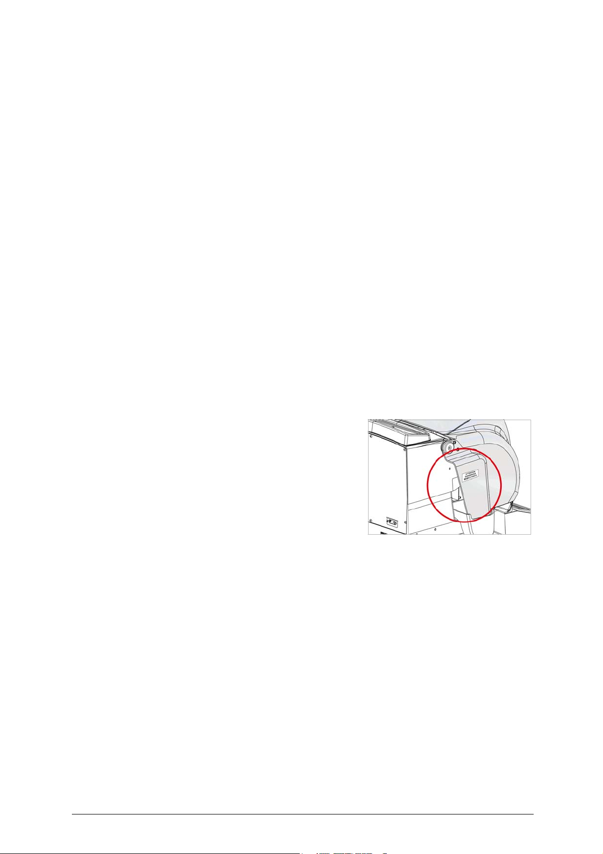
The UNOCODE PRO machine has residual risks in the highlighted area
shown in fig. 2.
P
ROTECTION AND SAFETY PRECAUTIONS FOR THE OPERATOR
UNOCODE PRO is entirely built in compliance to the Machine Directives. The operations for which it has been designed
are easily carried out with no risk to the operator.
The adoption of general safety precautions and observation of the instructions provided by the manufacturer in this
manual eliminate all human error, unless deliberate.
UNOCODE PRO is designed with features which make it completely safe.
• Power supply
UNOCODE PRO is supplied with electricity by means of a grounded plug and differential switch.
• Pneumatic power
With compressed air.
• Start-up
The machine is turned on by means of a master switch that is located on the Unocode’s lower left back side.
• Maintenance
The operations to regulate, service, repair and clean the machine are structured in the simplest and safest way possible.
Parts that the operator can dismount cannot be incorrectly replaced therefore avoiding any risks.
Fig. 2
2 Copyright Silca 2017

Operating manual - English UNOCODE PRO
• Machine identification
The machine is provided with an identification label which includes the machine’s serial number (fig. 3).
Fig. 3
(*) see Ch.9 "DISPOSAL", page 86.
GRAPHICS ON THE UNOCODE PRO KEY-CUTTING MACHINE
Do not clean with
compressed air
Adhesive label Mass - RPM
Unocode PRO
Obligation to read
the manual
Adhesive label Mass - RPM
Unocode PRO Flat Steel
Obligatory use
of safety goggles
Symbol on
UTP versions
Laser warning labels
(Ch. 1.2)
“DANGEROUS MOBILE PARTS”
Warning label
(Ch.1.5 "Accessories provided")
Place the adhesive label in the
appropriate language in position
as shown.
Copyright Silca 2017 3
UNOCODE PRO Operating manual - English
1 MACHINE DESCRIPTION
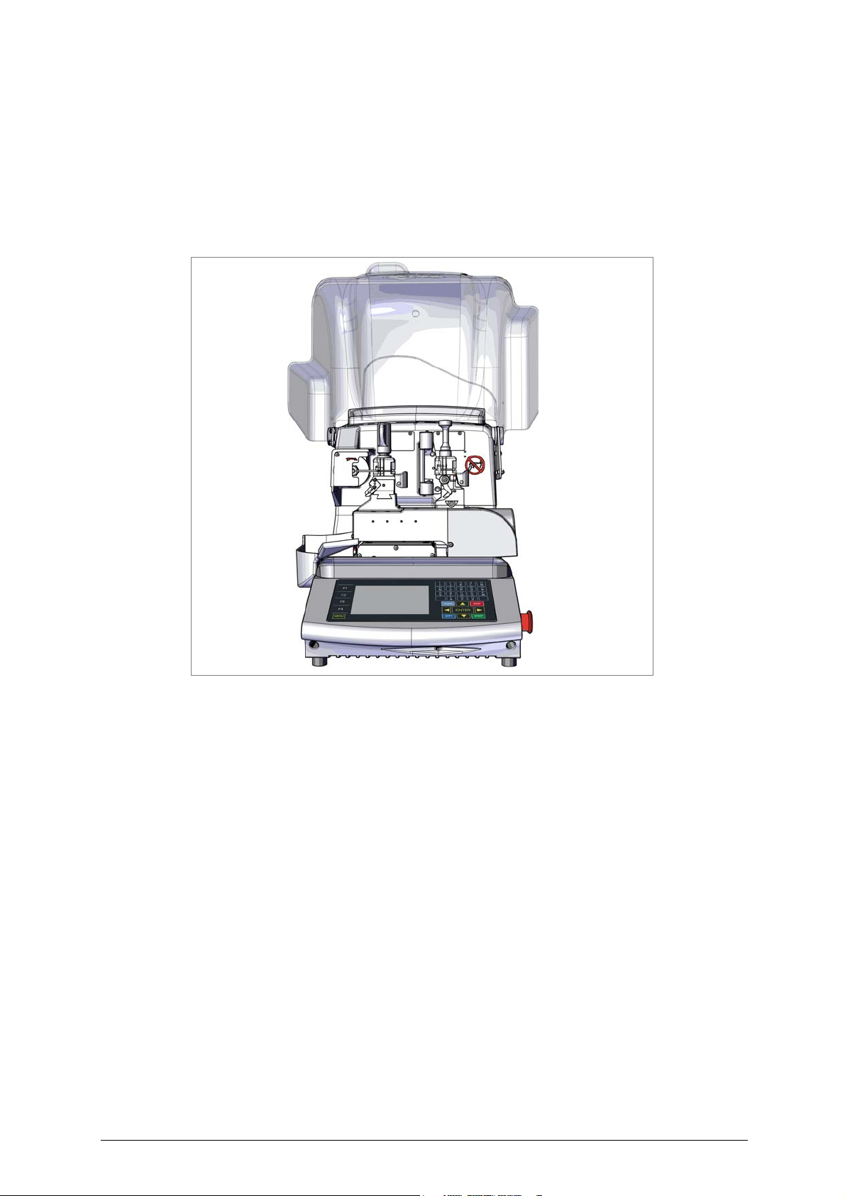
UNOCODE PRO is an electronic machine operating on two axes (3rd axis optional) with controlled movement. Accurately studied, it adds a high degree of cutting precision to operating speed and ease of use.
UNOCODE PRO can be used in 3 different ways:
• entering the key code directly by means of the machine keyboard
• reading the key with a laser reader and reproducing it
• linking to a PC and Silca software
Fig. 4
1.1 MAIN CHARACTERISTICS
•Movements
Movement of the two axes (X-Y) operates on ball screws activated by step motors, on rectified roller guides.
•Clamp
Standard four-sided clamp, specially designed to grip most flat keys.
• Working tool
Consists of a cutter in hard metal carbide, that is easily replaced.
Suitable to the type of work and speed rotation needed.
•Display
Placed on the front of the machine.
Its technical features and positioning make it highly practical in use.
• Laser reader
Designed to read cuts on keys to be reproduced
.
4 Copyright Silca 2017
Operating manual - English UNOCODE PRO
1.2 SAFETY
• Protective shield
The transparent protective shield is designed to cover the working parts as completely as possible, ensuring operator
safety.
The shield (U) (fig. 6, page 6) must be raised in order to fit keys for cutting or carry out other operations.
Raising of the shield is controlled by a microswitch and disactivates the operating and movement functions, including the
cutter. A special message appears on the display to warn that the shield is not closed.
To re-start the work cycle, place the shield in its original position and press START on the machine’s keyboard.
• Emergency stops
The red emergency button (N) (fig. 6, page 6) placed on the right-hand side of the machine is used to stop it immediately
in the event of faulty operation or danger for the operator.
When the cause of the emergency has been eliminated, turn the button 45° clockwise to disactivate it.
Note: the operator is responsible for keeping the area around the button clear so that it can be reached as quickly as
possible.
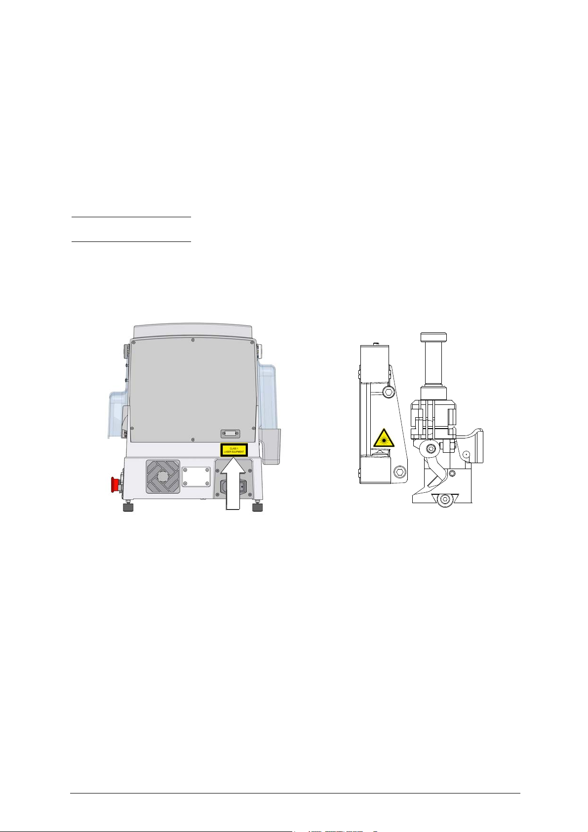
• Laser warning
Regulations require that warning label in the language to be used be attached to the back of the machine, as shown in
fig. 5.
The adhesives are in the accessories kit provided (Ch.1.5, page 8).
Fig. 5 - laser warning
• Cutter motor protection
The cutter motor is protected against overheating by a cut-out switch (located inside the motor) that will automatically
stop the motor if it reaches a certain temperature. Should the switch activate:
1) turn the machine off and disconnect the power supply cable.
2) contact Silca’s Technical Assistance Dept.
Copyright Silca 2017 5
UNOCODE PRO Operating manual - English
D
F
T
V
S
D1
F1
Q
E1
L
U
C B N O R
Q1
P
E
H
I
A
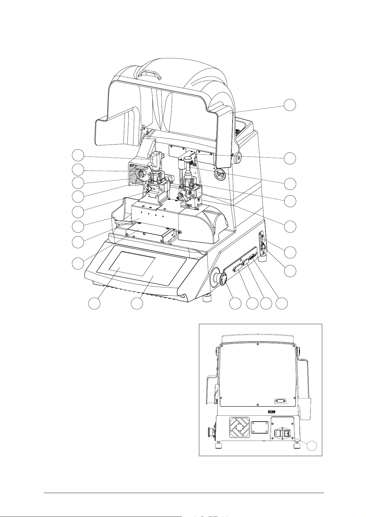
1.3 MAIN WORKING PARTS
Fig. 6
A - master switch
B - keyboard
C- display
D - clamp - cutter side
D1 - clamp - optical reader
E - clamp knob
E1 - optical reader clamp knob
F - key gauge - cutter side
F1 - key gauge - optical reader side
H - cutter
I - cutter shield
L - optical reader
N - emergency button
O - 3rd axis
P - IN/OUT port
Q - serial port
Q1 - USB port
R - Y axis connector
S - X axis carriage
T - Y axis carriage
U - protective shield
U2 - vacuum systems connector
V - swarf tray
6 Copyright Silca 2017

Operating manual - English UNOCODE PRO
1.4 TECHNICAL DATA
Electricity supply:
230V-50Hz
100V-50/60Hz
Nominal power:
230V: 1,1 Amp. 210 Watt
100V: 3,5 Amp. 310 Watt
Cutter motor:
single phase and speed
Cutter:
hard metal, coated
Tool speed
Unocode PRO: 50Hz: 1700 rpm (+/- 10%) 60Hz: 2040 rpm
Unocode PRO Flat Steel: 50Hz: 2340 rpm (+/- 10%) 60Hz: 2800 rpm
Movements:
on 2 axes with ball screws activated by step motors, on rectified roller guides.
Possibility to add a 3rd axis to activate the optional tilting and rotating clamps.
Clamp:
universal 4 sided clamp to grip flat, car and cruciform keys
Runs:
X axis: 57 mm Y axis: 32 mm
Dimensions:
width: 450 mm depth: 600 mm height: 440 mm (with raised shield 680 mm)
Mass:
Kg. 38
Noise level:
sound pressure Lp(A) = 80 dB(A) (cutting iron keys)
77 dB(A) (cutting brass keys)
:
Copyright Silca 2017 7

UNOCODE PRO Operating manual - English
1.5 ACCESSORIES PROVIDED
UNOCODE PRO comes with a set of accessories for its operation and maintenance (tools, hex wrenches, fuses)
supplied in a special tool kit comprising:
tool kit
tip stop bar with notch 13 mm spanner Z20 setting template
tip stop bar 2 Amp fuse - delayed Z3 template
cutter release rod (230V-50Hz)
1,5 mm allen key
2 mm allen key
2,5 mm allen key
10 mm spanner Z1 template
(regulating disk)
(regulating key)
Z4 serial test connector
4 Amp fuse - rapid
(100V-50/60Hz)
5 Amp fuse - rapid
10 Amp fuse - delayed belt tension plate
4 Amp fuse - delayed anti-tilting device
3 mm allen key
4 mm allen key
5 mm allen key
6 mm allen key
Adhesive label to attach to safety shield
6,3 Amp fuse - d el ayed ø 1,7 mm
steel pin
19 mm
socket wrench
slanted brush serial cable 9/9
laser warning label USB cable
ø 1,2 mm
steel pin
8 Copyright Silca 2017
Operating manual - English UNOCODE PRO
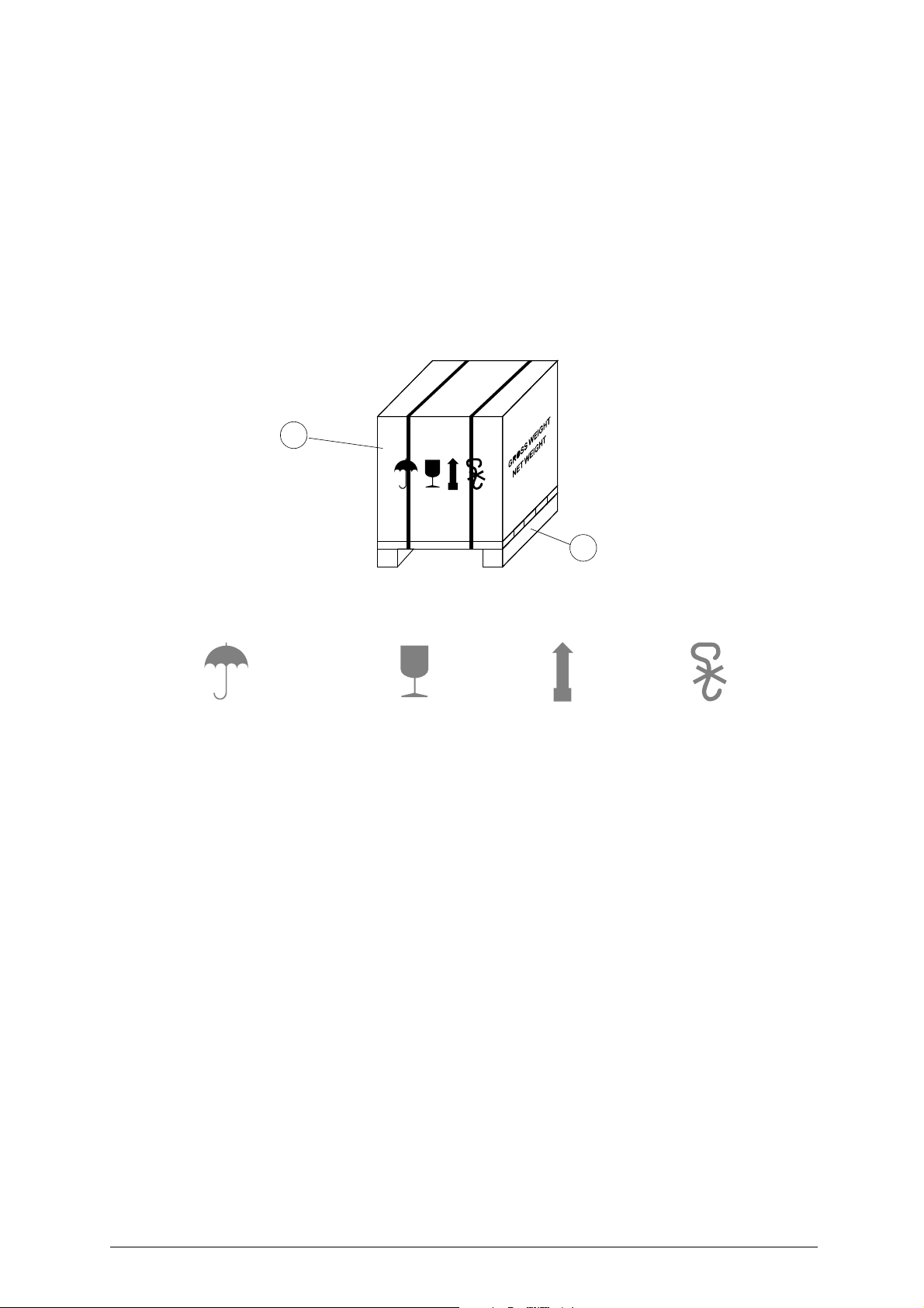
a
b
Keep dry
This side up
Handle with care
Use no hooks
2 TRANSPORT
The key-cutting machine is easily transported and is not dangerous to handle.
The packed machine should be carried by at least two people.
2.1 PACKING
The packing for UNOCODE PRO is designed to ensure safe transportation and to protect the machine and all its parts.
It comprises a pallet base (b) to which the machine is attached, and a cardboard box as a cover (a).
The machine is fixed to the base of the pallet with screwed down brackets that hold it firm into place. This prevents the
machine and its protective shield from any damage.
The closed packing is held in place by two straps which hold the cardboard box firmly on the pallet.
Symbols are printed on the outside of the cardboard box to give instructions and warnings for transportation.
Fig. 7
To prevent any damage to the machine it is advisable to save and use the brackets provided for future transportation
.
Copyright Silca 2017 9
UNOCODE PRO Operating manual - English
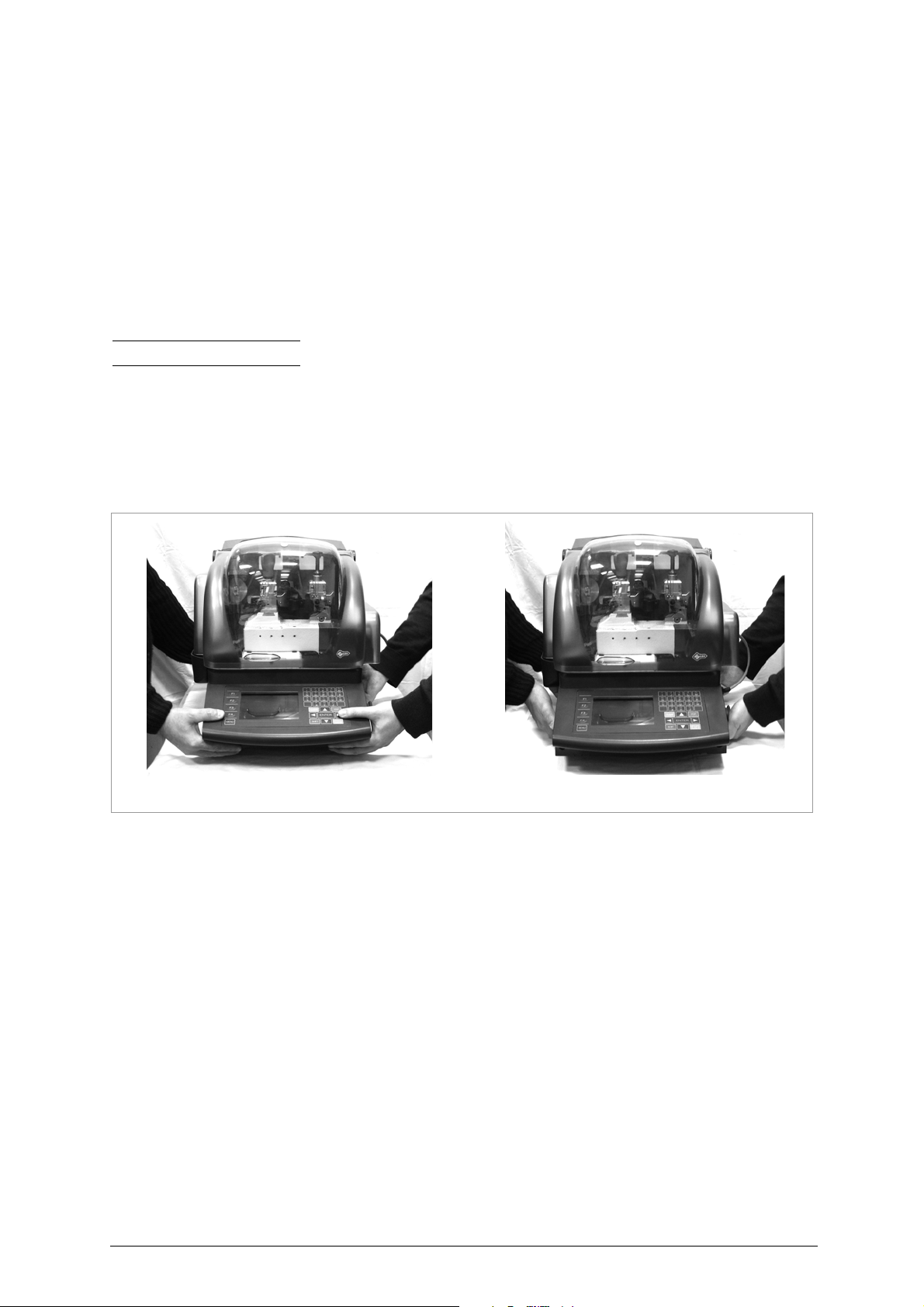
INCORRECT!
CORRECT
!
2.2 UNPACKING
To remove the machine from the packing box:
1) cut the straps with scissors and remove
2) raise the top part of the cardboard box
3) loosen the screws, both on the front and back brackets that hold the machine to the pallet
4) use the special spanner (provided in the tool kit), to loosen the nuts on the machine’s feet
5) remove the metal brackets and re-tighten the nuts on the feet.
6) check the contents in the box, that should comprise with the following:
1 UNOCODE PRO
1
set of documents, including: an operating manual, a spare parts list and a guarantee
1
power supply cable
1
tool kit
Note: we strongly recommend you keep the packing intact for future transportation
key-cutting machine
2.3 MACHINE HANDLING
When the UNOCODE PRO has been unpacked, place it directly on its workbench; this operation should be carried out by
at least two people.
Take care to lift the machine firmly holding the base, and no other part.
ATTENTION: never lift the machine by holding the keyboard stand (fig. 8).
Fig. 8
10 Copyright Silca 2017
Operating manual - English UNOCODE PRO
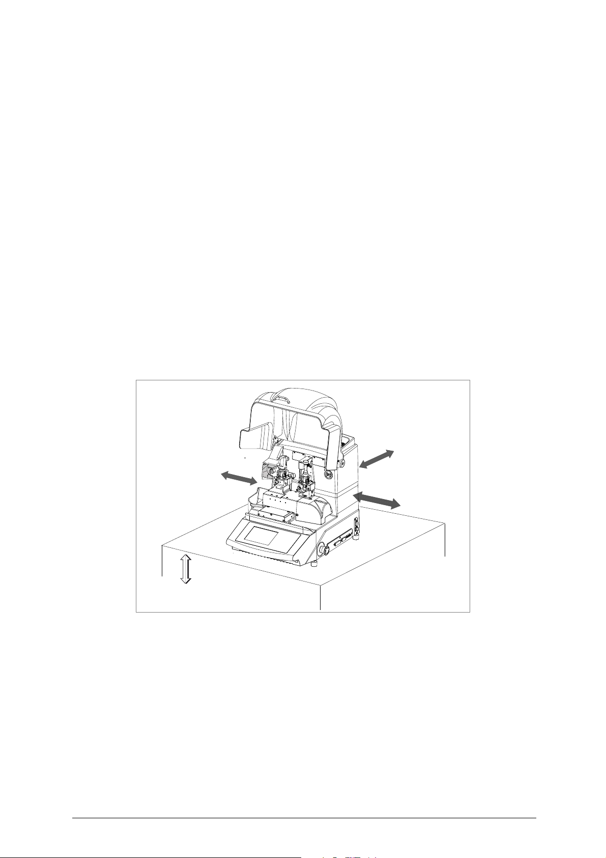
100/120 cm
30 cm
30 cm
30 cm
3 MACHINE INSTALLATION AND PREPARATION
The key-cutting machine can be installed by the purchaser and does not require any special skills.
It is supplied ready for use and does not need any special set up. However, the operator may have to control a few things
before operating the machine.
3.1 CHECKING FOR DAMAGE
UNOCODE PRO is solid and compact and will not normally damage if transport, unpacking and installation have all been
carried out according to the instructions in this manual. However, it is always advisable to check that the machine has not
suffered any damage.
3.2 ENVIRONMENTAL CONDITIONS
To ensure that the best use is made of the key-cutting machine, it is important to place it in a well-aired area which is not
too damp.
The ideal conditions for the machine are: temperature between 10°C and 40°C; relative humidity: approx 60%
3.3 POSITIONING AND INSTALLATION
1) Place the machine on a horizontal surface, solid enough to support the weight of 38 Kg.
- to work with ease, we suggest that the workbench be approximately the height of the operator’s hip.
- it is important to leave clearance of at least 30 cm behind the machine and on each side to ensure proper ventilation.
2) Ensure that the machines voltage is the same as that of the mains power supply, which must be properly earthed
and provided with a differential switch.
3) Connect the power supply cable to the power supply socket.
Fig. 9
3.4 DESCRIPTION OF WORK STATION
The machine needs only one operator, who has the following controls at his/her disposal (fig. 6, page 6):
• master switch placed on the back of the machine
• key-positioning clamp
• keyboard
•display
• emergency button
Copyright Silca 2017 11
UNOCODE PRO Operating manual - English
Clamp - cutter side Clamp - Optic Reader side
V100 R100
1
2
3
4
2
3
1
4
2
C
4
3
2
3
4
1
4
D
B
A
2
1
1
3
D side
C side
B side
A side
1
2
3
4
0
B
4
3
1
C
D
4
3
1
A
4
3
2
1
6
4 “SET UP” AND USE OF THE MACHINE
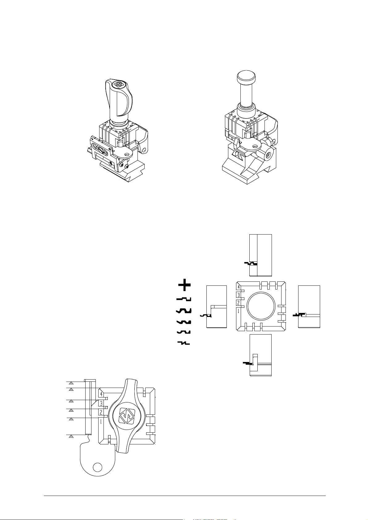
4.1 USE OF THE CLAMP
Fig. 10
The four-sided clamp ensures excellent grip on the keys placed on their back or profile sides (fig. 11).
• Keys with 1 or 2 cuts to reproduce by code should be fitted mainly on the A and/or B side of the clamp.
• When copying with the optical reader the key can be fitted to any side (A, B, C or D) of the clamp.
- For keys to be cut by code the side of the clamp
on which to place the key is shown on the
machines display.
- For keys to be copied with the optical reader the
side of the clamp to be used is at the discretion
of the operator.
-
To fit keys with tip stops on the optic reader
clamp, fit the bar provided into the special
grooves
(fig. 12).
Fig. 11
12 Copyright Silca 2017
Fig. 12 - key stops
Operating manual - English UNOCODE PRO
D5
E
Attention: the pin
should be placed
vertically
2
C
4
3
2
3
4
1
4
D
B
A
2
1
1
3
broken keys
pin
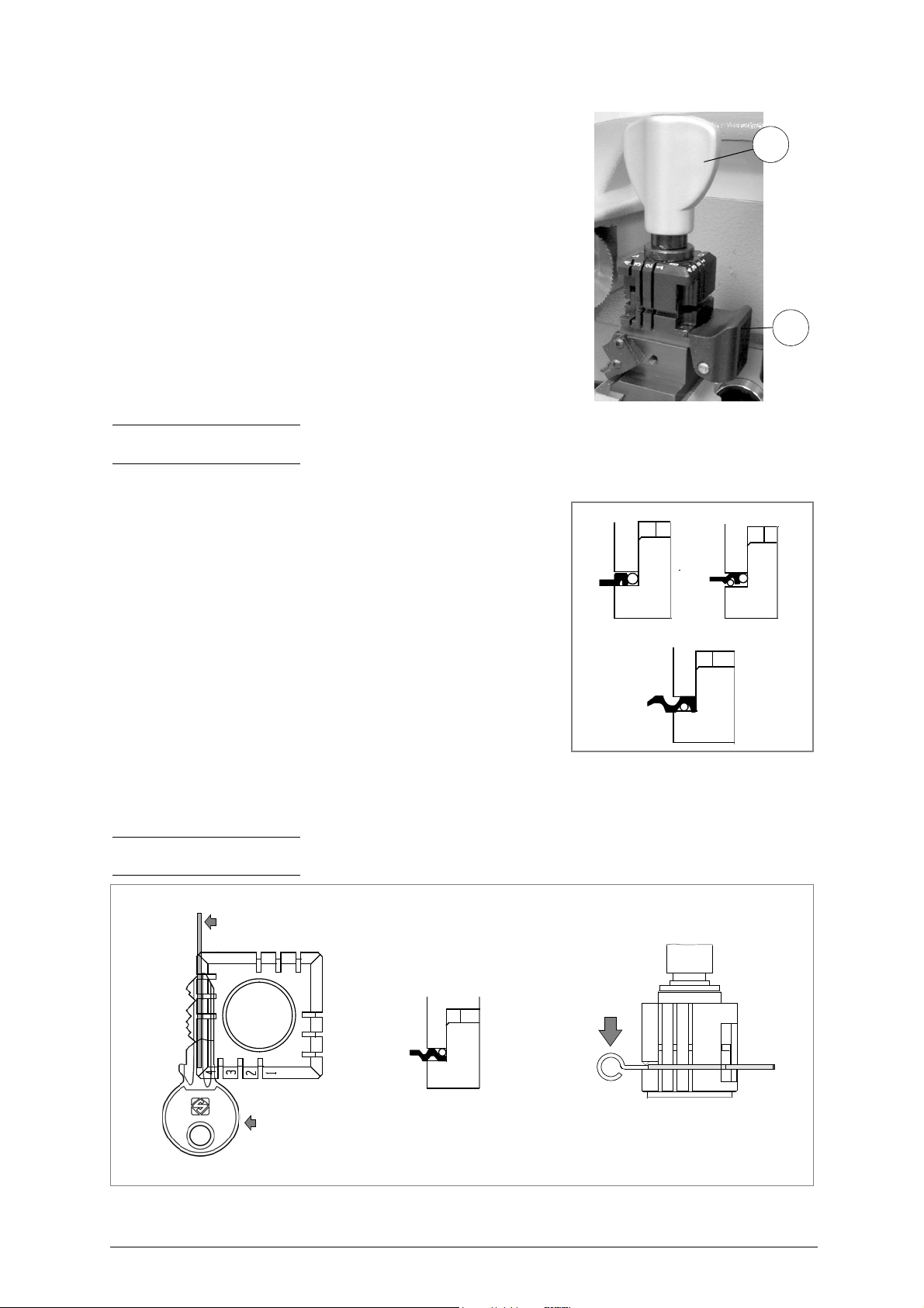
ATTENTION: the knobs are gauged so that they do not exert too much
pressure for closing (if pressure is too high they only idle), which would
damage the key and the parts of the clamp (including the knob).
To turn the clamps:
With loosened handle (E) a light rotation of the clamp is sufficient
(gripping by the 2 jaws) to turn it to the required side. Alignment is
automatic and guaranteed by the mobile pressure device (D5) (fig. 13).
Fig. 13
Note: before starting to cut a key the V100 clamp gauge goes automatically to the idle position so there is no need to
lower it, but the R100 clamp gauge must be lowered manually.
U
SING THE PINS
Copying with the optical reader
For keys with narrow stems the pins must be placed between the bottom of
the clamp and the back of the key so that the key protrudes sufficiently out of
the clamp and therefore can be properly read and cut.
If the key has a narrow stem and is also very thin, 2 pins must be used (fig.
14).
Fig. 14
If the original key is broken, place a suitable sized pin in the groove of the keys stem so that it is properly held in place
and therefore can be copied (fig. 15).
Note: the diameter of the pin used for the original key must be the same as that of the pin used for the blank key; only
in this way will the two keys be locked in the same position.
Fig. 15
Copyright Silca 2017 13
UNOCODE PRO Operating manual - English
F2
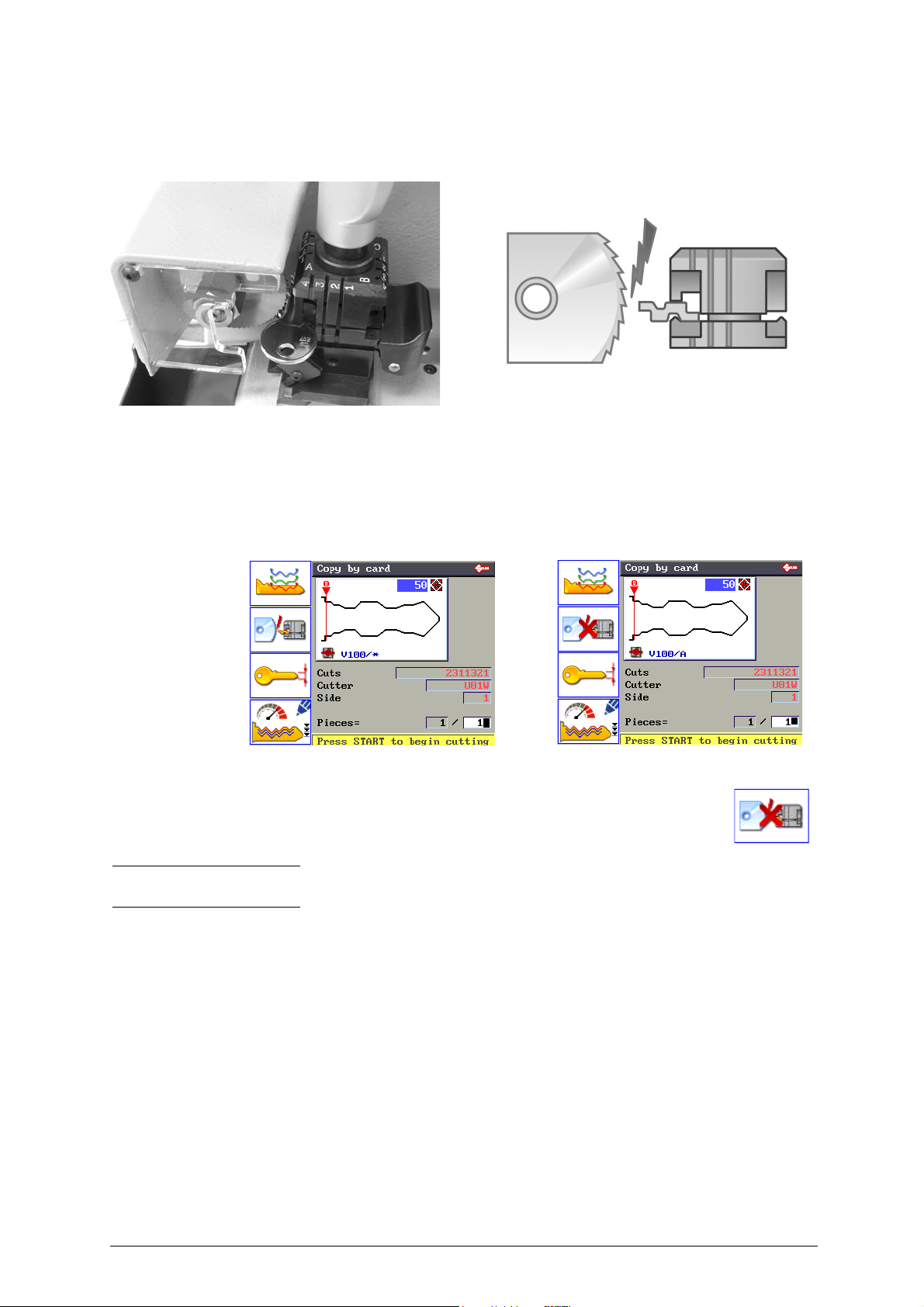
4.2 CUTTING BY ELECTRIC CONTACT
The UNOCODE PRO key-cutting machine is equipped with a low voltage electrical contact device which permits the
cutter to individualize the key blank as it approaches the cutter during the cutting phase (fig. 16).
Fig. 16
This technical solution permits the operator to secure the key to the more appropriate side of the 4 faced clamp (A, B, C
or D) therefore improving the grip on the key and eliminating the need of pins and/or adaptors.
With the electrical contact card enabled, depth calibration is automatically calculated when the cutter touches the keys
profile during the cutting process.
Electrical contact is guaranteed for keys in steel, brass, silver nickel, Zamak or iron (with or without nickel-plating).
• Press F2 to enable or disable the electrical contact function to read the key blank measurements.
The symbol * in the clamp field means that the key will be cut reading the key
blank measurements by electrical contact.
A red “X” on the electrical contact icon means that it has been disabled.
Note: some cutting cards do not include electrical contact. In such cases the software does not allow
editing.
4.2.1 IMPROPER USE OF ELECTRIC CONTACT
It is not permitted to cut ultralite anodized aluminium keys, plastic keys or any keys with materials that
do not have electrical conductivity by means of electric contact.
ATTENTION: for these types of materials, insert standard cutting.
Cuts cannot be repeated on the same side of the key when electric contact cutting is used.
All data cards provided by Silca are in the machine’s memory. The cards are enabled or disabled for code cutting by
electric contact at Silca’s discretion.
14 Copyright Silca 2017
Operating manual - English UNOCODE PRO
D2
X1
X
i2
i
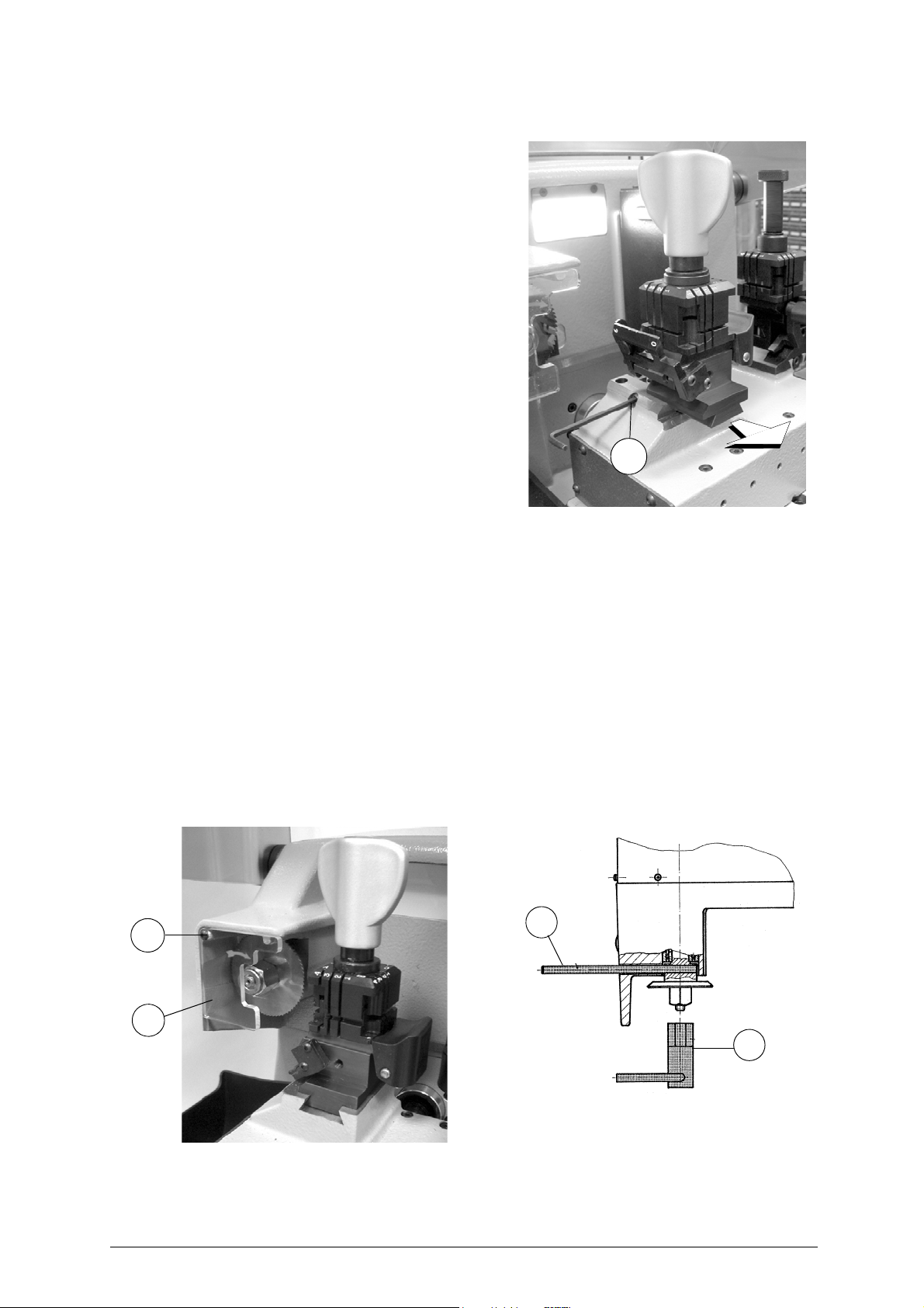
4.3 FITTING THE CLAMP TO THE MACHINE
To remove the clamp unit:
- loosen the grub screw (D2) (fig. 17) and slide the clamp out of the
dovetail guide.
To install the clamp unit on the machine:
- slide the clamp into the dovetail guide, pushing it all the way in,
then secure it by tightening the grub screw (D2).
These instructions refer exclusively to the standard clamp (V100).
For the use of optional clamps please refer to the instructions
provided along with them.
Fig. 17
4.4 CUTTER
The majority of keys utilize the standard cutter for code cutting. Only in certain cases some special keys with particular
type cuts require different cutters.
To change the cutter see chapter 4.5.
4.5 CHANGING THE CUTTER
1) raise the protective shield.
2) remove the cutter protective shield (i) by loosening the screw (i2).
3) slide the cutter release rod (X) into the hole located on the left side of the machines cutter shaft chassis (fig. 18).
4) loosen the cutter locking nut (turning it clockwise) with the19 mm socket wrench (X1) provided with the machine.
ATTENTION: the thread is left-handed.
5) replace the cutter, then tighten the nut (turning it counter-clockwise) and remove the rod from its hole.
6) place the cutters protective shield (i) back into position securing it with the screw (i2).
Fig. 18
ATTENTION: when replacing a worn cutter with a new one or with a re-sharpened cutter consult Ch.6.9 "GAUGING",
page 46.
Copyright Silca 2017 15

UNOCODE PRO Operating manual - English
5 UNOCODE PRO VERSION UTP
Note: UTP function is NOT enabled on Unocode PRO FLAT STEEL.
The UNOCODE Pro UTP (Unlimited Token Plan) is a “timed use” key-cutting machine.
On cutting the first key a free one month “UTP” is automatically activate d. At the end of that
period a message appears: the customer has another 30 days in which to purchase a UTP
package.
At the end of the period (1 month free + 30 days) the machine can no longer be used to cut
keys (it is operative only for decoding ). To continue using all the machine functions contact
a Silca distributor to purchase another UTP package (Ch.6.11.2 "UTP SETTINGS").
• “UTP (Unlimited Token Plan)” is a special “timed digital token” that allows the machine to be used freely
(unlimited number of keys can be cut) for a given period (up to 31 December of the calendar year in
progress).
• When the UTP package has expired 30 days of Extratoken are available before the key-cutting function is
blocked. (Ch 6.11.2 "UTP SETTINGS").
• After purchasing a new UTP package download it from the Internet by means of the “Silca Remote
Service” program (SRS) (Ch.6.8.1 "DOWNLOAD THE UTP PACKAGE").
16 Copyright Silca 2017
Operating manual - English UNOCODE PRO
UNOCODE PRO
UNOCODE PRO UTP
6 OPERATING GUIDE
Introduction
The Operating Guide below explains how to use the UNOCODE PRO without a Personal Computer.
All operations to manually use the key-cutting machine are explained step by step.
The programs available for Personal Computers connected to the key-cutting machine are able to transmit data for
cutting, reading or decoding keys.
Programs for Personal Computer eliminate manual procedures of certain functions, once the data has been transmitted
to the machine it bypasses some of the operating guides screens.
When the UNOCODE PRO is used with a Personal Computer, the operating guide does not change its displays logic,
with the exception of all the screens that are rendered unnecessary.
6.1 INITIAL OPERATIONS
When the key-cutting machine has been placed on its workbench and connected to the mains (Ch.3.3, page 11), proceed
as follows:
1)
make sure that the emergency button is not turned on
2) turn the machine on by means of the main switch that is located on the back of the machine.
3) to check or alter the parameters for use of the machine, consult the "OPTIONS" menu (Ch.6.11, page 61).
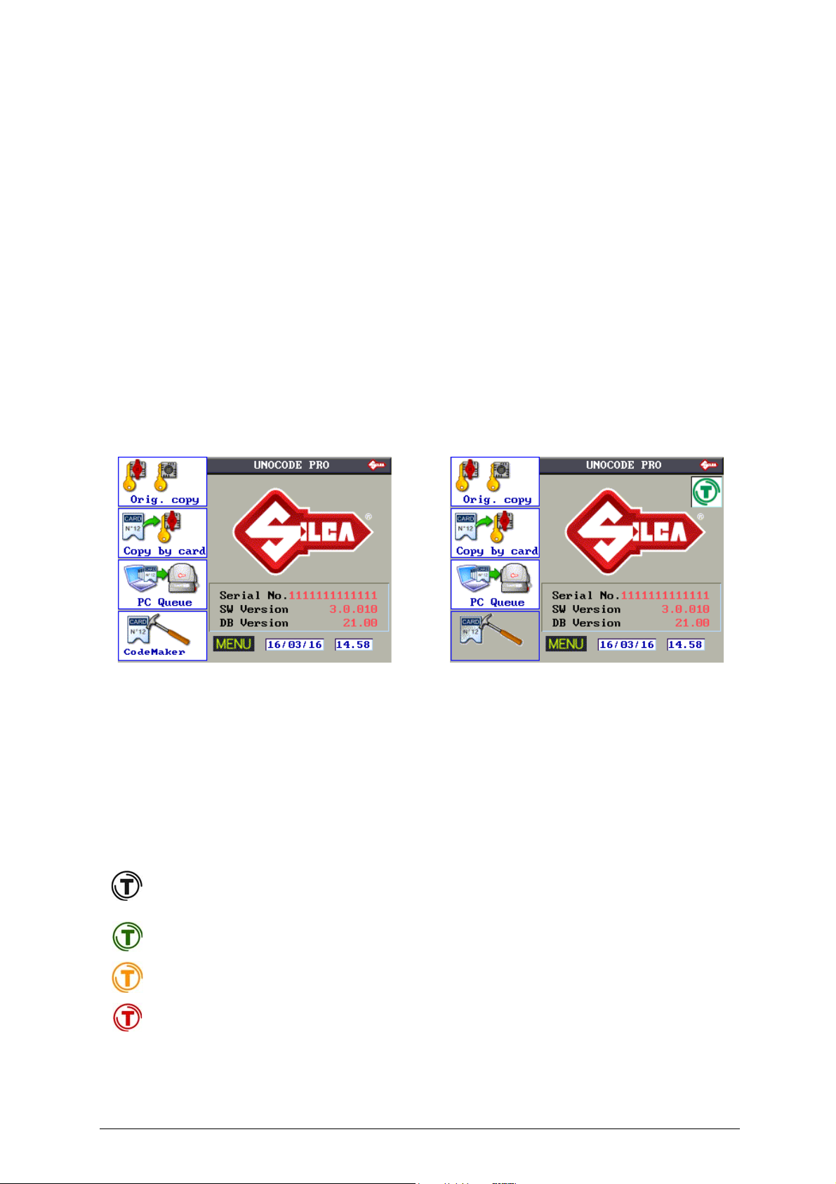
When the machine is turned on the display shows the following screen:
.
Fig. 19
Besides the first 4 icons relating to the main functions, listed on the left, the following information appears:
• Name of the key-cutting machine
• Serial number of the key-cutting machine
• SW version: machine program version
• DB version: version of the cutting card Database on board the machine
•Date
•Time
• Flashing word MENU (press MENU to view the other main functions)
• Machine in UTP mode (Unlimited Token Plan)
GREEN:
YELLOW:
days of use exceed the minimum warning poi nt set in the Options => UTP Settings (Ch.6.11 .2)
days of use are below the minimum warning point set in the Options => UTP Settings (Ch.6.11.2)
RED:
days of use have expired or are about to expire (Ch.6.11.2)
Copyright Silca 2017 17
UNOCODE PRO Operating manual - English
6.2 MACHINE KEYBOARD AND FUNCTION BUTTONS
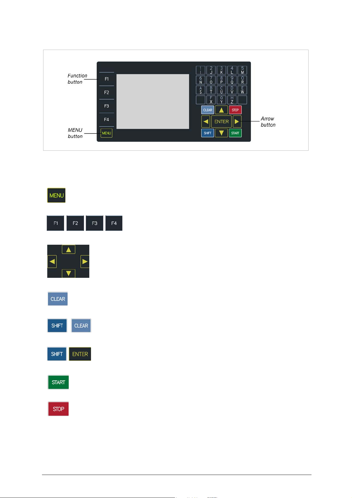
Fig. 20
The MENU key is used to view the list of main functions:
MENU key: is always active from any of the windows.
Function keys: select the on-screen options
Arrow keys: used to move the pointer (navigation) in the on-screen fields
CLEAR: used to delete a single character
SHIFT+ CLEAR: pressed together to delete an entire row
SHIFT+ ENTER: pressed together to insert a digit space
START: starts the procedure
STOP: cancels the operation and/or returns to the previous menu.
18 Copyright Silca 2017
Operating manual - English UNOCODE PRO
F1
F2
F3
F4
F1
F2
F3
F4
F1
F2
F3
F4
F1
F2
F3
F4
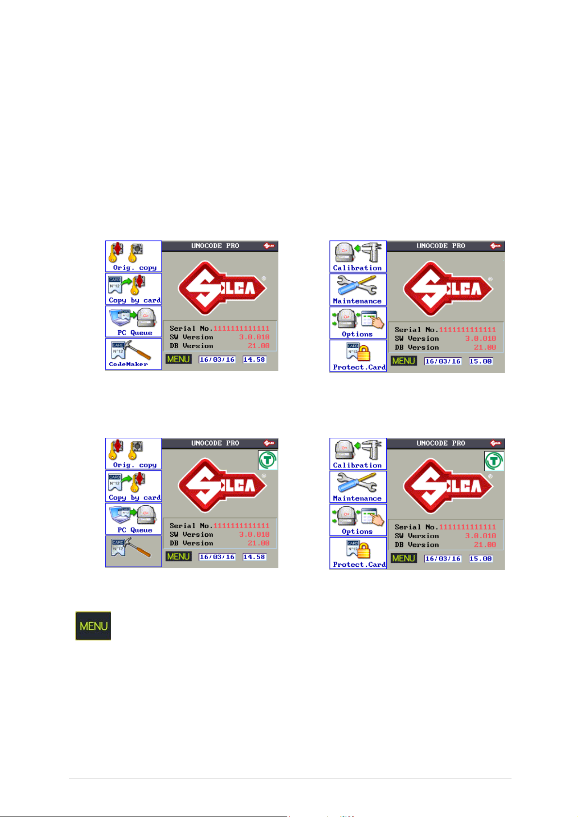
Main menu functions
• Copy from Original
• Copy card
•PC queue
• CodeMaker (not enabled on the UTP version)
• Gauging
• Maintenance
•Options
•Enabling
UNOCODE PRO
UNOCODE PRO UTP
Press the MENU key repeatedly to view the list of icons relating to the main
functions of the machine program.
Copyright Silca 2017 19
UNOCODE PRO Operating manual - English
20
A
1 3 4
Stop 2
Gauge
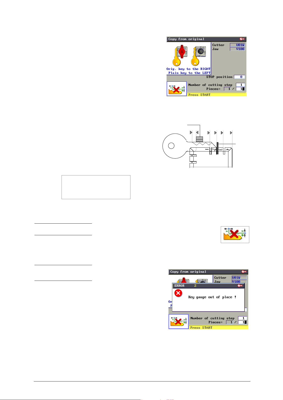
6.3 COPY FROM ORIGINAL
In the initial screen press F1 to use the function.
This function is used to make a direct copy from the key, without
further stages.
The “Copy from Original” window shows certain data and icons:
• Cutter to use (cannot be edited)
• Clamp to use (cannot be edited)
• Stop position (settings go from 0 to 6; other values can be
written but will not be confirmed)
• No. of cutting step: (can be edited) increases the number of
cutting passes (max. 3).
• Pieces = 1 / 1(up to 999 pcs. can be set)
Stop distance:
The number shown on the machine’s display represents the X axis
distance between the key blank shoulder and the beginning of the first
cut.
This function is extremely important with keys that require cuts on
both sides as it ensures precise positioning on the key 2nd side.
The set figure is 50 hundredths of a mm, which can be varied:
• min.0 - max. 99 hundredths of a mm.
ATTENTION: settings that are too high may render precise cuts
impossible, with the following message on the display:
MIN. Parameter of
DISTANCE FROM STOP
is incompatible with
selected card!
Note: the icon in the lower left corner of the menu can be activated by the F4 key (see Ch.6.4 "Copy
with adjustments", page 21).
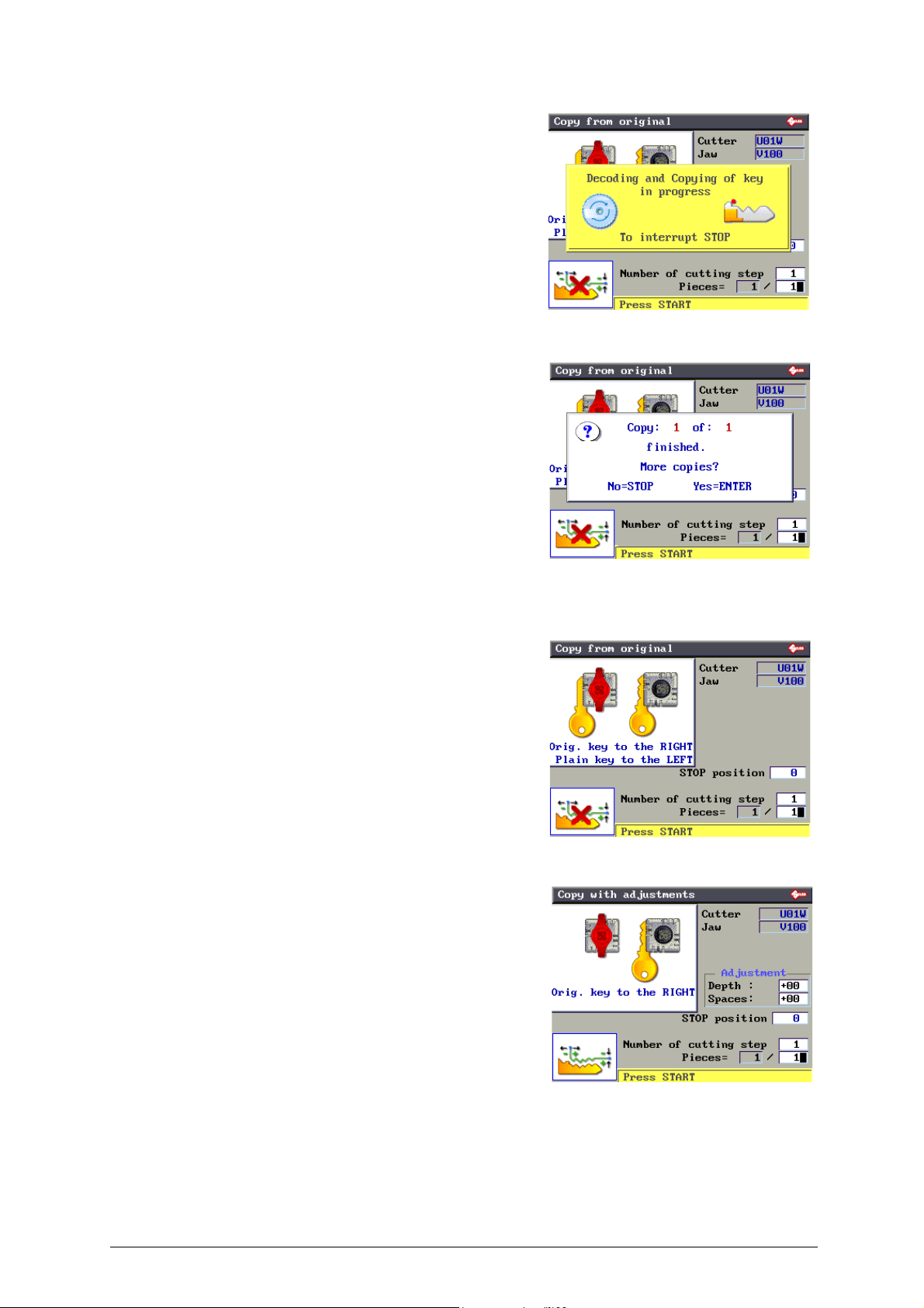
Set the number of pieces to be cut, the type of Stop to use (up/down arrow keys to move and numerical keys for entry).
As illustrated in the figure, with Stop 0 and pieces 1, fit the key blank into the clamp on the cutter side and the original key
into the clamp on the reader side. Lower the right-hand clamp gauge and press START to begin.
Note: after placing the original key in the r/h clamp, remember to
lower the gauge. If this is not done, when reading starts the machine
will stop and show the following message on the display:
In this case lower the gauge and press START to continue.
20 Copyright Silca 2017
Operating manual - English UNOCODE PRO
F4
F4
First the display will show:
and then:
- Press STOP to confirm the end of the operation.
- Press ENTER if you wish to cut other keys.
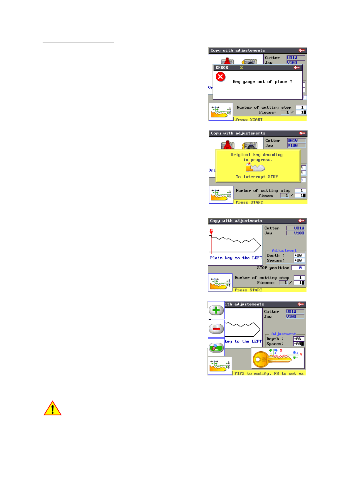
6.4 COPY WITH ADJUSTMENTS
In this mode an original key is copied in 3 stages:
• Reading
• Setting up of adjustments
• Cutting
The icon in the lower left corner of the menu can be activated
by the F4 key.
Press F4 again to return to the “Copy from Original” menu.
When you click on F4 the screen changes:
- The icon/figure of the original key placed in the right/hand
clamp (reader side) and an empty left-hand clamp (cutter
side:
A box appears containing adjustments in depth and spaces.
- Press START to start reading.
Copyright Silca 2017 21
UNOCODE PRO Operating manual - English
F1
F2
F3
F4
Note: after placing the original key in the r/h clamp, remember
to lower the gauge. If this is not done, when reading starts the
machine will stop and show the following message on the
display:
In this case lower the gauge and press START to continue.
When reading is finished, to enter the adjustments, use the “up/
down” arrow keys over the fields (Depths and Spaces) in which
the adjustments are to be made:
• Press F1 to get positive values (+).
• Press F2 to get negative values (-).
• Press F3 to cancel the set adjustments.
Adjustments possible for Depth (-30 to + 30 hundredths of
a millimetre):
- One value (positive or negative) raises or lowers all cuts.
Adjustments possible for Spaces (-30 to +30 hundredths
of a millimetre):
- One value (positive or negative) moves all the cuts (from the
stop) to the right or left.
Warning! The presence of this symbol indicates that adjustments to the card have been
applied!
22 Copyright Silca 2017
Operating manual - English UNOCODE PRO
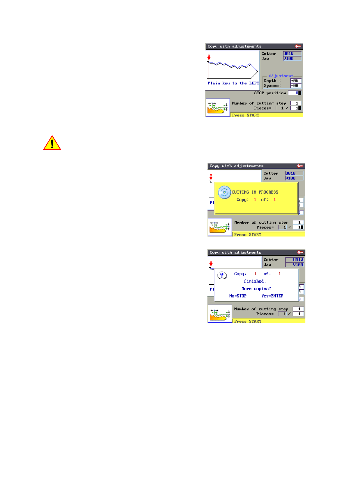
Press ENTER to view the “new” key with the adjustments
made.The display will show:
- a black outline of the original key (key read).
- a blue outline of the key to be cut, with the adjustments made.
Fit the key blank into the clamp on the cutter side and secure.
Lower the safety shield and press START to proceed with
cutting.
Warning! The presence of this symbol indicates that adjustments to the card have been
applied!
First the display will show:
and then:
• Press STOP to confirm the end of the operation.
• Press ENTER if you wish to cut other keys.
Copyright Silca 2017 23
UNOCODE PRO Operating manual - English
F1
F3
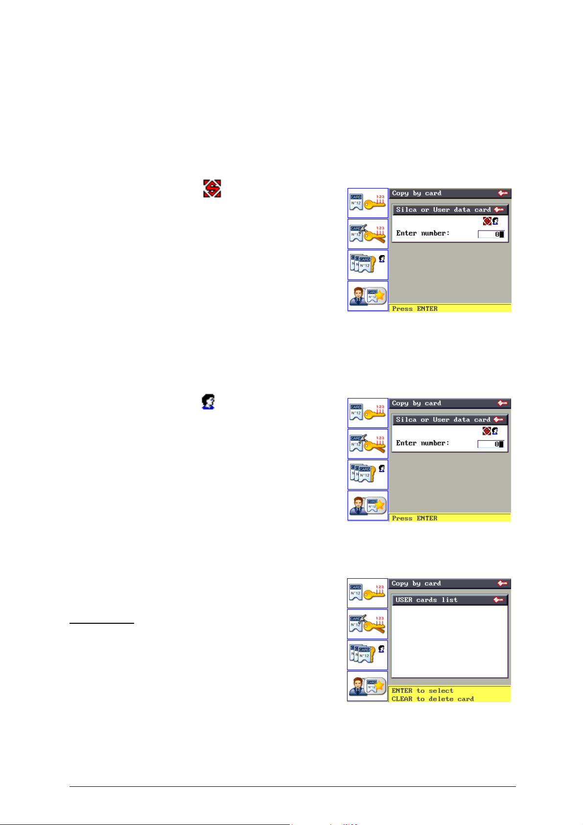
6.5 COPY FROM CUTTING CARD
From the initial screen press F2 to use the function.
One part of the machine’s internal memory is used as a cutting card archive.
A cutting card is a database of “Spaces”, “Depths” and cutting angles for all the keys Silca considers can be taken into
consideration.
SILCA and USER cutting cards can be selected by pressing F1.
• SILCA cutting cards
SILCA cards are found in:
- Paper catalogues
- Electronic catalogue
- Silca Key Programs
Certain parameters on SILCA cards can be edited, but
the adjustments CANNOT BE SAVED in the machine
memory.
The number of SILCA cards is periodically increased with the
“Silca Code Program” update, which can be purchased
separately. Through the Silca Code Program the user can
update the program and data on the machine.
• USER cutting cards
Cards customized using Silca Key Programs on the PC and sent
to the machine. They can be:
- Created with Code Maker of SKP
- Silca SKP cards with certain parameters edited.
Certain parameters on USER cards can be edited and
editing CAN BE SAVED in the machine memory.
• Press F3 to view the list of User cutting cards.
Operational keys:
Up/Down arrows: to scroll cards
ENTER: to select
CLEAR: to delete selected card
24 Copyright Silca 2017
Operating manual - English UNOCODE PRO
F2
F3
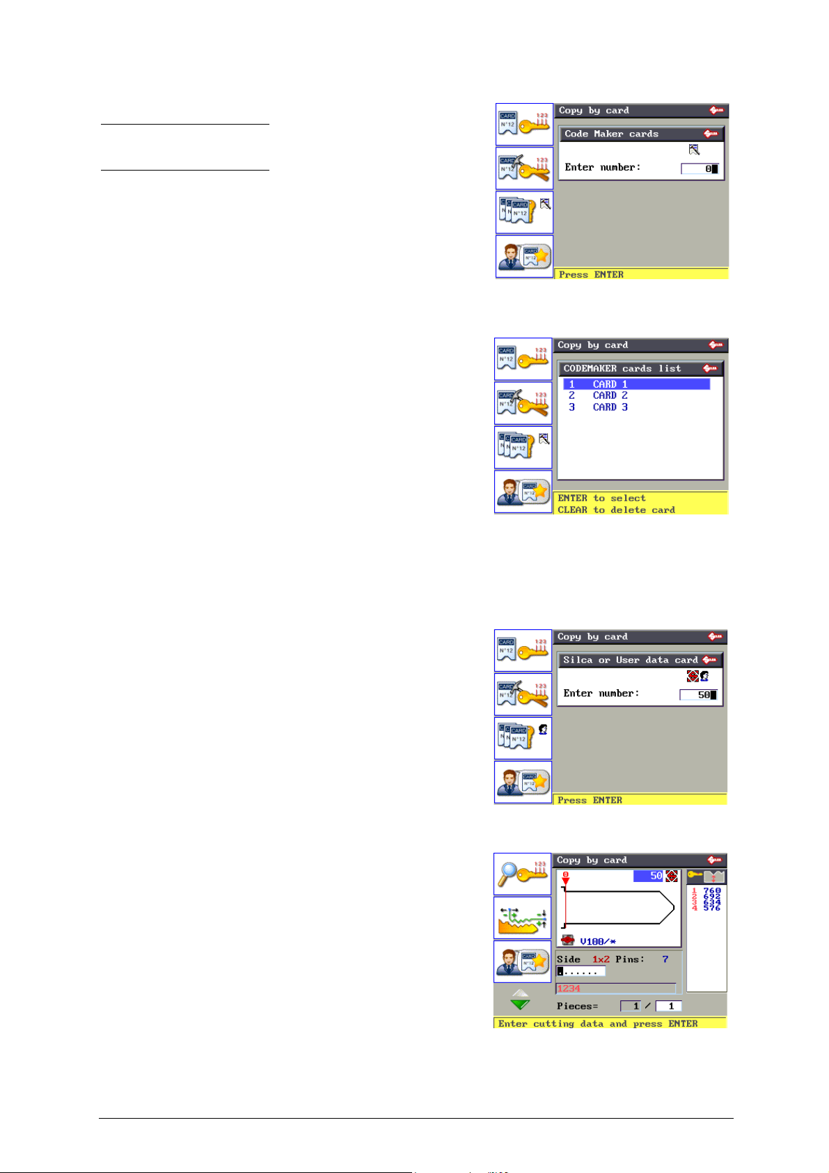
• CODEMAKER cutting cards:
Note: on the UTP version the Search for cutting cards created
with Codemaker (optional program) is run only through the Silca
Key Program.
Customized cards created using CODE MAKER on the machine.
• Press F3 to view a list of CodeMaker cards.
EXAMPLE: Copy from SILCA cutting Card
1) Digit the card number (e.g.: 50):
Press ENTER, the display shows:
. . . . . . .
The dots shown represent possible cuts. The same card can be used
for a number of keys with a different number of cuts.
If a key is used with fewer cuts than the dots on the display, just digit a
partial combination.
2) Digit the cuts.
• Single side Side 1
• Double symmetric Side 1x2
• Double asymmetric Side 1 / Side 2
Copyright Silca 2017 25
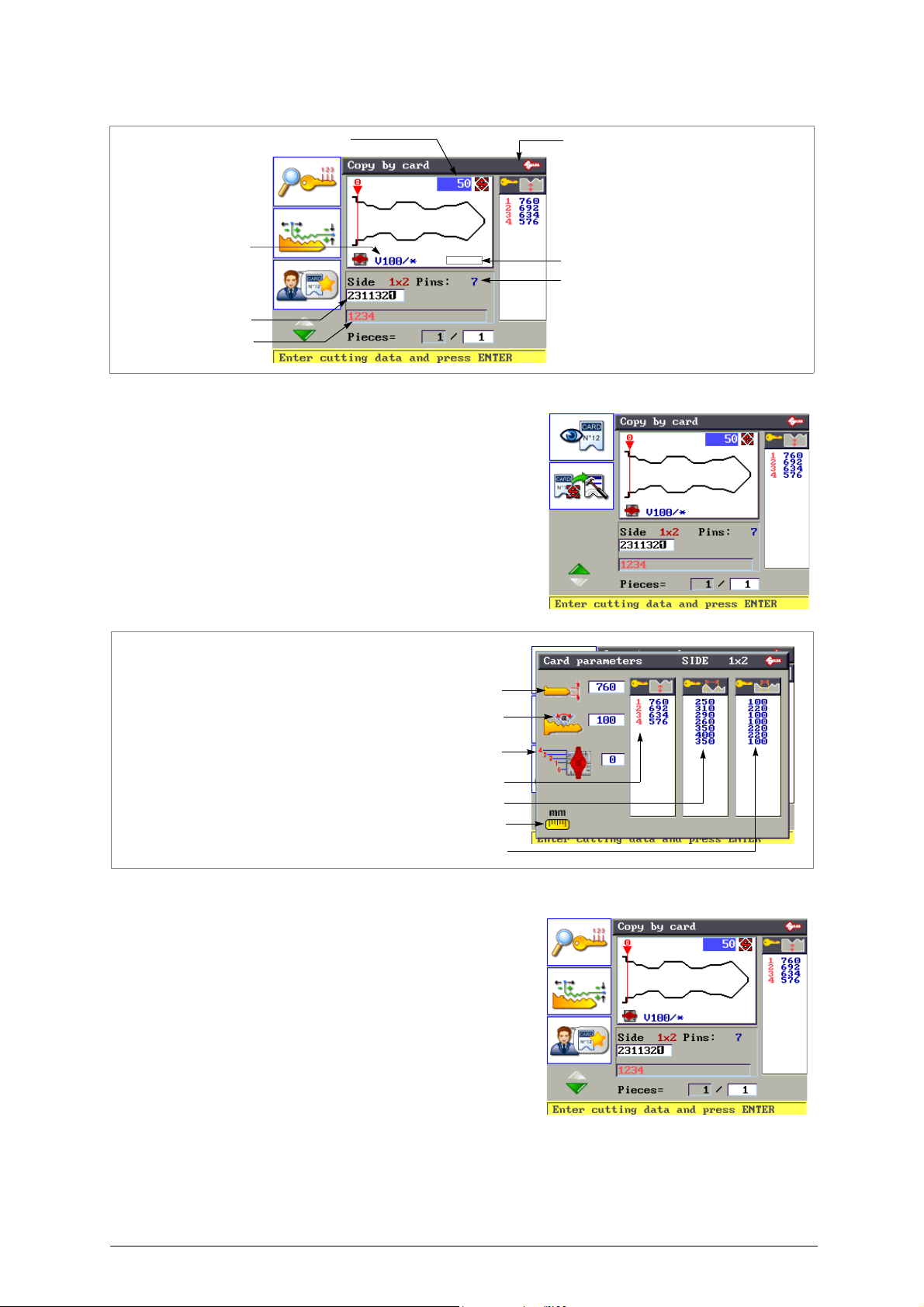
UNOCODE PRO Operating manual - English
Card No
Number of cuts per side for current key
Cutting
Symbols associated to cutting depths
Symbols allowed
Adapter if applicable
Clamp to use
F1
Key blank measurements
Cutting angle
Symbols associated to cutting depths
Cutting spaces
Base of the cuts
Measuring unit
Key stop
F2
Fig. 21
• Press F1 to consult the cutting parameters on the card.
Press STOP to exit.
• Press F2 to set up manual adjustment of cutting depths
and spaces (the adjustment values entered can be saved
as User Parameters).
26 Copyright Silca 2017
 Loading...