

Page 1
Operating manual
D437711XA
vers. 2.0
®
EN
Page 2

(c) 2010 SILCA S.p.A. - Vittorio Veneto
This manual is written by SILCA S.p.A.
All rights reserved. No part of this publication may be reproduced or used in any form or by any means (photocopying, microfilm or other) without the
written permission of SILCA S.p.A.
Edition:
July 2016
Printed in Vittorio Veneto
by SILCA S.p.A.
via Podgora, 20 (Z.I.)
31029 VITTORIO VENETO (TV) - Italy
IMPORTANT NOTE: in compliance with current regulations relating to industrial property, we hereby state that the
trade-marks or trade names mentioned in our documentation are the exclusive property of authorized
manufacturers of locks and users.
Said trade-marks or trade names are nominated only for the purposes of information so that any lock for which our
keys are made can be rapidly identified.
Page 3

INDEX
REFERENCE GUIDE ..........................................................................................................................1
GENERAL ............................................................................................................................................2
1 MACHINE DESCRIPTION ..........................................................................................................4
1.1 MAIN CHARACTERISTICS .......................................................................................................... 4
1.2 S
1.3 M
1.4 T
1.5 A
2 TRANSPORT ............................................................................................................................10
2.1 PACKING ...............................................................................................................................10
2.2 U
2.3 M
3 MACHINE INSTALLATION AND PREPARATION ..................................................................12
3.1 CHECKING FOR DAMAGE ........................................................................................................ 12
3.2 E
3.3 P
3.4 D
3.5 G
4 “SET UP” AND USE OF THE MACHINE .................................................................................14
4.1 USE OF THE CLAMP ............................................................................................................... 14
4.2 F
4.3 C
4.4 C
5 OPERATING GUIDE .................................................................................................................17
5.1 ON-BOARD KEYPAD AND FUNCTIONS ......................................................................................17
5.2 P
5.3 C
5.4 SPECIAL CASES ................................................................................................................ 31
5.5 PC QUEUE FUNCTION ........................................................................................................ 33
5.6 CODEMAKER
5.7 GAUGING ........................................................................................................................... 40
5.8 MAINTENANCE ..................................................................................................................44
5.9 OPTIONS ............................................................................................................................52
5.10 ENABLING ..........................................................................................................................55
5.11 M
AFETY ...................................................................................................................................5
AIN WORKING PARTS ............................................................................................................. 6
ECHNICAL DATA ....................................................................................................................8
CCESSORIES PROVIDED ......................................................................................................... 9
NPACKING ...........................................................................................................................11
ACHINE HANDLING ............................................................................................................... 11
NVIRONMENTAL CONDITIONS ................................................................................................ 12
OSITIONING AND INSTALLATION .............................................................................................12
ESCRIPTION OF WORK STATION ............................................................................................13
RAPHICS .............................................................................................................................13
ITTING THE CLAMP TO THE MACHINE .....................................................................................16
UTTER ................................................................................................................................16
HANGING THE CUTTER ......................................................................................................... 16
RELIMINARY OPERATIONS ....................................................................................................18
OPY BY DATA CARD ............................................................................................................ 19
5.3.1 FAVOURITE DATA CARDS ................................................................................................. 24
5.3.2 ACCESSORY FUNCTIONS FOR “COPY BY DATA CARD” ........................................25
5.4.1 CUTS NOT ALLOWED ....................................................................................................... 31
5.4.2 L
IMITED ACCESS TO DATA (PROTECTED SYSTEMS) ........................................................... 32
CARD MANAGEMENT ......................................................................................36
5.7.1 CALIBRATE STANDARD JAWS ...................................................................................... 41
5.7.2 C
5.7.3 C
ALIBRATE CUTTERS ................................................................................................... 43
ALIBRATE ADAPTERS ................................................................................................. 43
5.8.1 MOTOR TESTS ............................................................................................................ 44
5.8.2 DIGITAL INLETS TEST ................................................................................................ 44
5.8.3 DIGITAL OUTLETS TESTS .......................................................................................... 45
5.8.4 KEYPAD TEST ............................................................................................................. 45
5.8.5 DISPLAY TEST ............................................................................................................ 45
5.8.6 SERIAL PORT .............................................................................................................. 45
5.8.7 MACHINE ZERO POINTS ............................................................................................ 46
5.8.8 PHOTOCELLS AND SENSORS REGULATION .......................................................... 49
ESSAGES ............................................................................................................................56
5.11.1 ATTENTION MESSAGES .................................................................................................... 56
5.11.2 E
5.11.3 A
5.11.4 CODEMAKER
RROR MESSAGES .......................................................................................................... 58
LARM MESSAGES .......................................................................................................... 59
MESSAGES .............................................................................................. 60
Page 4

6 CLEANING ................................................................................................................................62
7 MAINTENANCE ........................................................................................................................63
7.1 TROUBLE SHOOTING .............................................................................................................. 63
7.2 M
7.3 C
7.4 B
7.5 C
7.6 E
7.7 K
7.8 A
7.9 A
7.10 S
7.11 P
7.12 B
7.13 WIN-TRANSFER P
AINTENANCE OPERATIONS ................................................................................................... 65
UTTER REPLACEMENT .......................................................................................................... 65
ELT REPLACEMENT AND TENSION ADJUSTMENT ..................................................................... 66
HECKING AND/OR REPLACING FUSES ....................................................................................67
LECTRONIC CIRCUIT BOARD REPLACEMENT ...........................................................................68
EYBOARD/DISPLAY REPLACEMENT ........................................................................................69
CCESS TO BACK COMPARTMENT ..........................................................................................70
CCESS TO BOTTOM COMPARTMENT ......................................................................................70
ENSOR REPLACEMENT ......................................................................................................... 71
HOTOCELL REPLACEMENT .................................................................................................... 73
ATTERY REPLACEMENT ........................................................................................................ 74
ROGRAM ................................................................................................ 75
8 DISPOSAL ................................................................................................................................76
9 ASSISTANCE ...........................................................................................................................77
9.1 HOW TO REQUEST SERVICE ................................................................................................... 77
Appendix 1 - ELECTRICAL DIAGRAM ..........................................................................................I - XI
Appendix
2 -
DECLARATION COMPLIANCE
Page 5
Operating manual - English Unocode 399 PLUS
2
1
5
3
6
4
1
3
7
5
7
2
NUMERO SCHEDA
Card Number
FROM SILCA KEY CATALOGUE
REFERENCE GUIDE
This manual has been produced to serve as a guide for users of the
Read it carefully; it is essential if you wish to operate your machine safely and efficiently
C
ONSULTATION
The contents of the manual are divided into sections relating to
• Machine description ...................................................................................................Chapter 1
• Transport and installation ...................................................................................................Chapters 2-3
• Regulation and use ...................................................................................................Chapters 4-5-6
• Maintenance ...................................................................................................Chapters 7-8-9
T
ECHNICAL TERMS
Common technical terms are used in this manual.
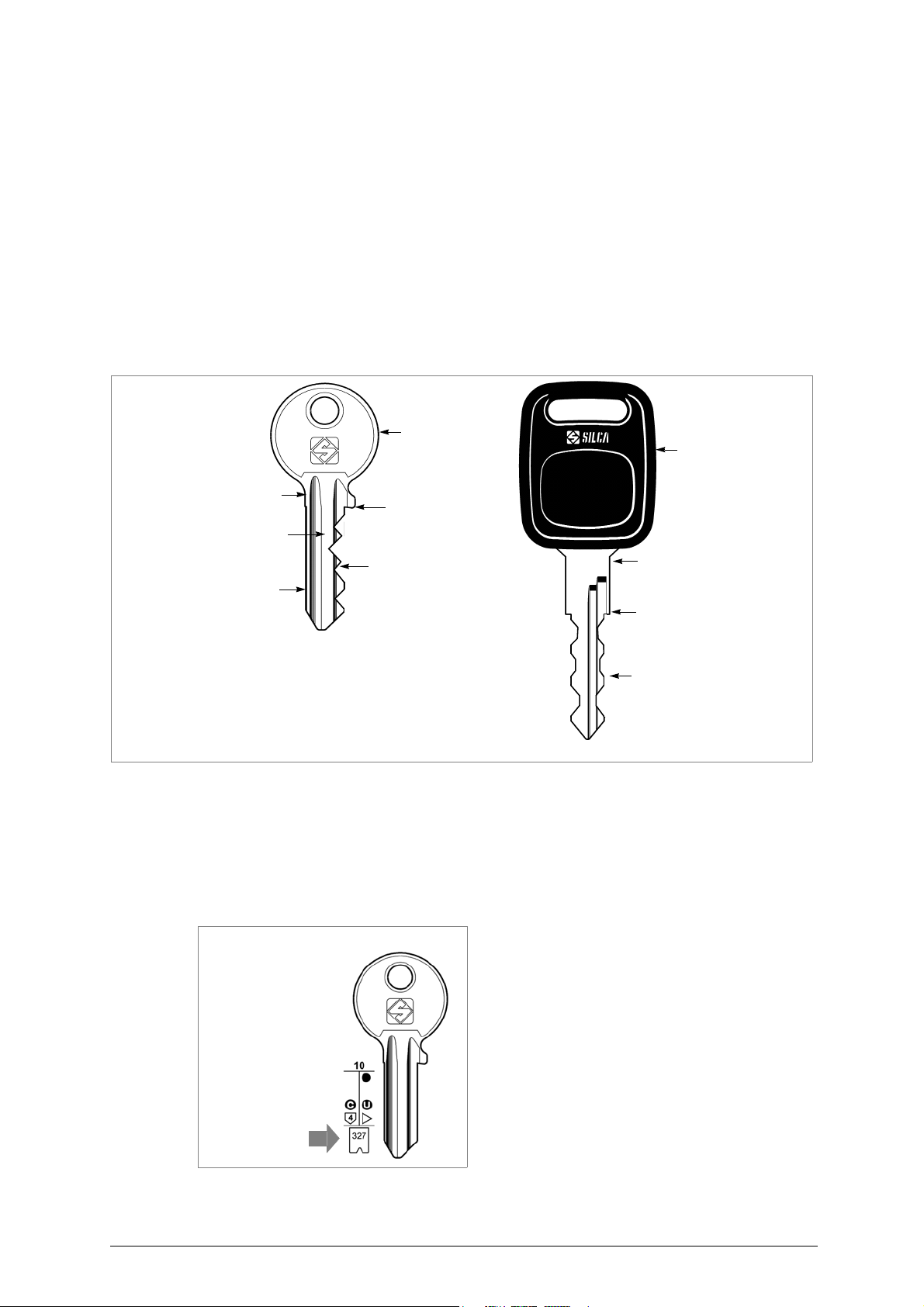
To assist those with little experience of keys and key-cutting, below is an illustration of the terms most frequently used
UNOCODE 399 PLUS
:
electronic key-cutting machine.
.
.
Fig. 1
1) Head
2) Rim
3) Stop
4) Stem
5) Tip
6) Back
7) Cuts
CARD NUMBER:
Silca number for cutting by code on Silca electronic
machines for flat keys.
Fig. 2
Copyright Silca 2016 1
Page 6

Unocode 399 PLUS Operating manual - English
GENERAL
UNOCODE 399 PLUS
From the design stage, risks for the operator have been eliminated in all areas: transport, regulation, cutting and maintenance.
Further risks have been eliminated by means of protective devices.
The materials used to manufacture this machine and all its components are not hazardous
U
SE
UNOCODE 399 PLUS
It must be installed and used according to the instructions indicated by the manufacturer.
If the key-cutting machine is used differently or for purposes different from those described in this manual, the customer will forego
any rights he may have over Silca S.p.A. Furthermore, unforeseen danger to the operator or any third parties may arise from
incorrect use of the machine
I
NSTRUCTIONS MANUAL
The instructions manual provided with the machine is essential to its proper use and to carry out the
necessary maintenance.
We therefore recommend protecting the manual from damage in a safe sheltered place, easily to
hand for quick consultation.
I
NCORRECT USE
Operator negligence resulting in improper use of this machine or failure of the operator to observe the instructions written in this
manual. The manufacturer may decline all guarantees and responsibilities.
It is therefore essential to carefully read this operating manual
F
URTHER RISKS
No further risks will arise when properly using the
P
ROTECTION AND SAFETY PRECAUTIONS FOR THE OPERATOR
UNOCODE 399 PLUS
designed are easily carried out with no risk to the operator
The adoption of general safety precautions and observation of the instructions provided by the manufacturer in this manual
eliminate all human error, unless deliberate
UNOCODE 399 PLUS
•
Power supply
UNOCODE 399 PLUS
•
Pneumatic power
With compressed air
•
Start-up
The machine is turned on by means of a master switch that is located on the Unocode’s lower left back side
•
Maintenance
The operations to regulate, service, repair and clean the machine are structured in the simplest and safest way possible. Parts that
the operator can dismount cannot be incorrectly replaced therefore avoiding any risks
has been designed in compliance to the European Community normative (CE).
is designed for cutting keys of ferrous materials: brass, silver nickel, etc.
.
.
UNOCODE 399 PLUS.
is entirely built in compliance to the Machine Directives. The operations for which it has been
.
is designed with features which make it completely safe
is supplied with electricity by means of a grounded plug and differential switch
.
.
.
.
.
.
.
2 Copyright Silca 2016
Page 7
Operating manual - English Unocode 399 PLUS
•
Machine identification
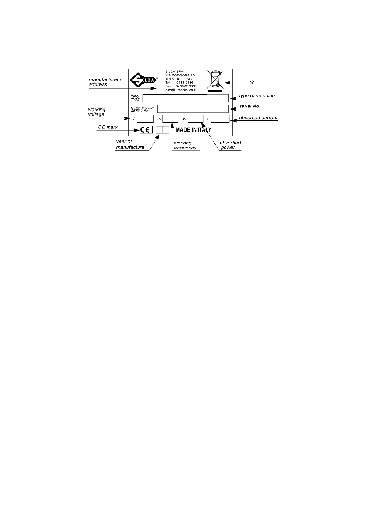
Fig. 3
The machine is provided with an identification label which includes the machine’s serial number
(*)
see
chap.8 "DISPOSAL", page 76.
(fig. 3).
Copyright Silca 2016 3
Page 8
Unocode 399 PLUS Operating manual - English
1 MACHINE DESCRIPTION
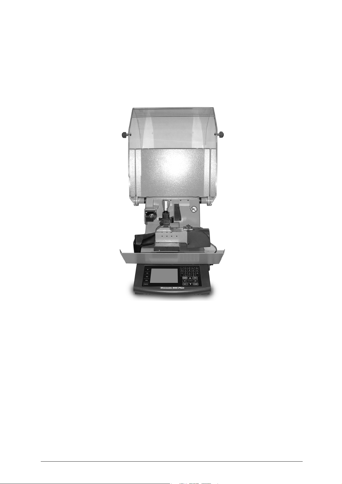
UNOCODE 399 PLUS is an electronic machine operating on two axes (3rd axis optional) with
controlled movement. Accurately studied, it adds a high degree of cutting precision to operating speed
and ease of use.
UNOCODE
• entering the key code directly by means of the machine keyboard
• linking to a PC and Silca software
can be used in different ways
:
Fig. 4
1.1 MAIN CHARACTERISTICS
•
Movements
Movement of the two axes (X-Y) operates on ball screws activated by step motors, on rectified roller guides
•Clamp
Standard four-sided clamp, specially designed to grip most flat keys
• Working tool
Consists of a cutter in hard metal carbide, that is easily replaced.
Suitable to the type of work and speed rotation needed
•Display
Placed on the front of the machine
Its technical features and positioning make it highly practical in use
4 Copyright Silca 2016
.
.
.
.
.
Page 9

Operating manual - English Unocode 399 PLUS
1.2 SAFETY
• Protective shield
The transparent protective shield is desig ned to cover the working parts as completely as possible,
ensuring operator safety.
The shield (U) (fig. 5, page 6) must be raised in order to fit keys for cutting or carry out other
operations.
Raising of the shield is controlled by a microswitch and disactivates the operating and movement
functions, including the cutter. A special message appears on the display to warn that the shield is not
closed.
To re-start the work cycle, place the shield in its original position and press START on the machine’s
keyboard.
• Emergency stops
The red emergency button (N) (fig. 5, page 6) placed on the right-hand side of the machine is used to
stop it immediately in the event of faulty operation or danger for the operator.
When the cause of the emergency has been eliminated, turn the button 45° clockwise to disactivate it.
Note: the operator is responsible for keeping the area around the button clear so that it can be reached as quickly as
possible.
• Cutter motor protection
The cutter motor is protected against overheating by a cut-out switch (located inside the motor) that will automatically stop the
motor if it reaches a certain temperature. Should the switch activate
1) turn the machine off and disconnect the power supply cable.
2) contact Silca’s Technical Assistance Dept.
:
Copyright Silca 2016 5
Page 10
BC
D
E
F
H
I
P
O
Q
S
U
V
Q1
U1
T N
R
KJ
Unocode 399 PLUS Operating manual - English
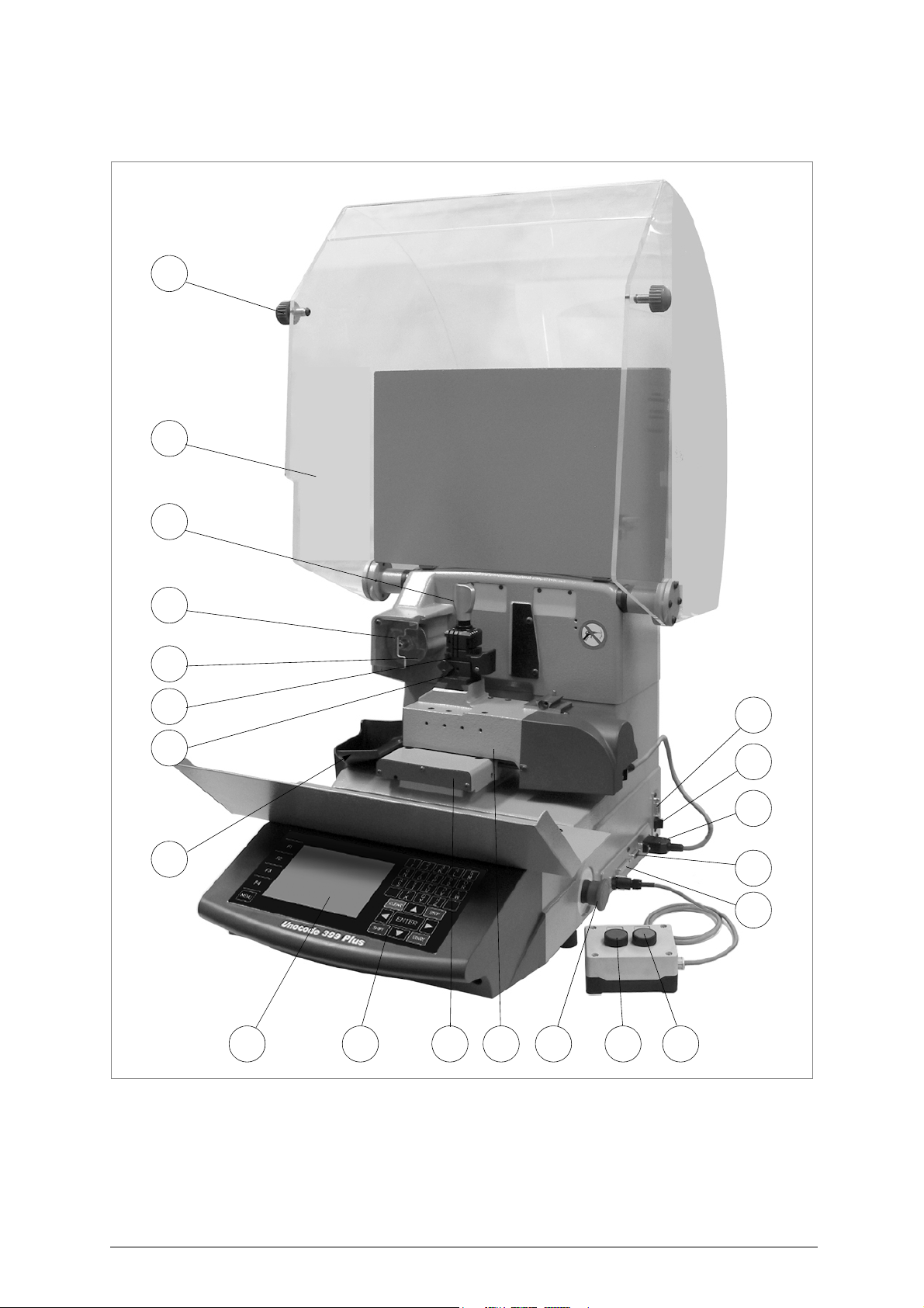
1.3 MAIN WORKING PARTS
Fig. 5
6 Copyright Silca 2016
Page 11
Operating manual - English Unocode 399 PLUS
AA1 ROPJ K
Q1
L
L2
Q
L1
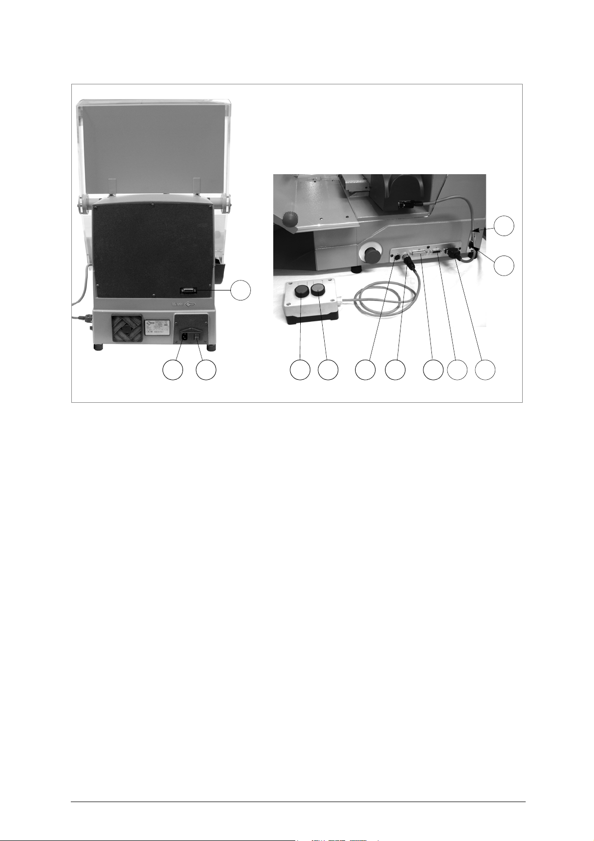
Fig. 6
A - master switch
A1 - power socket / fuse tray
B - keyboard
C- display
D - clamp - cutter side
E - clamp knob
F - key gauge
H - cutter
I - cutter shield
J - STOP button
K - START button
L - external START/STOP connector
L1 - connector for unload sorter (*)
L2 - serial receptacle for suction (*)
N - emergency button
O - 3rd axis
P - IN/OUT port (Automatic feeder*)
Q - serial port
Q1 - USB port
R - Y axis connector
S - X axis carriage
T - Y axis carriage
U - protective shield
U2 - vacuum system connector
V-swarf tray
(*) Feeder Kit, Suction Kit and Sorter Kit are optional accessories.
Copyright Silca 2016 7
Page 12

Unocode 399 PLUS Operating manual - English
1.4 TECHNICAL DATA
Electricity supply
230V-50Hz
Nominal power
230V: 1,1 Amp. 210 Watt
cutter motor
single phase and speed
cutter
:
hard metal
Tool speed
50Hz: 1700 rpm (+/- 10%)
Movement
on 2 axes with ball screws activated by step motors, on rectified roller guides.
Possibility to add a 3rd axis to activate the optional tilting and rotating clamps
Clamp
:
universal 4 sided clamp to grip flat, car and cruciform keys
Runs
:
X axis
: 57 mm
Dimensions
width
: 500 mm
Mass
:
Kg. 51
Noise level
sound pressure
:
:
:
:
s:
Y axis:
: 32 mm
:
depth
: 700 mm
:
Lp(A) = 80 dB(A) (
height
77 dB(A) (
: 700 mm (
with raised shield
cutting iron keys
cutting brass keys
.
900 mm)
)
)
8 Copyright Silca 2016
Page 13
Operating manual - English Unocode 399 PLUS
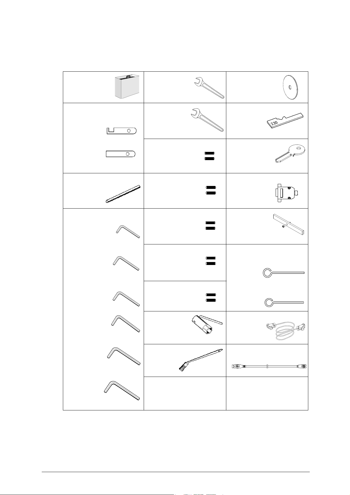
1.5 ACCESSORIES PROVIDED
UNOCODE 399 PLUS
supplied in a special tool kit comprising
tool kit
D931090ZR
tip stop bar with notch
tip stop bar D912423ZR
D900754ZR
cutter release rod
D931082ZR
2 mm allen key
comes with a set of accessories for its operation and maintenance (tools, hex wrenches, fuses)
:
10 mm spanner D916657ZR
13 mm spanner Z20 setting template
2 Amp fuse
- delayed
D901185ZR
4 Amp fuse
- rapid
D916568ZR
10 Amp fuse
- delayed
Z1 template
(regulating disk)
D916658ZR
Z3 template
(regulating key)
Z4 serial test connector
belt tension plate
D908726ZR
2,5 mm allen key
3 mm allen key
4 mm allen key D906963ZR
5 mm allen key D906935ZR
6 mm allen key
4 Amp fuse
- delayed
D910652ZR
6,3 Amp fuse
- delayed
19 mm
socket wrench
slanted brush
D933777ZR
ø 1,7 mm steel pin
ø 1,2 mm steel pin
D909281ZR
serial cable 9/9
D929095ZR
USB cable
Copyright Silca 2016 9
Page 14
Unocode 399 PLUS Operating manual - English
a
b
Keep dry
This side up
Handle with care
Use no hooks
2 TRANSPORT
The key-cutting machine is easily transported and is not dangerous to handle.
The packed machine should be carried by at least two people
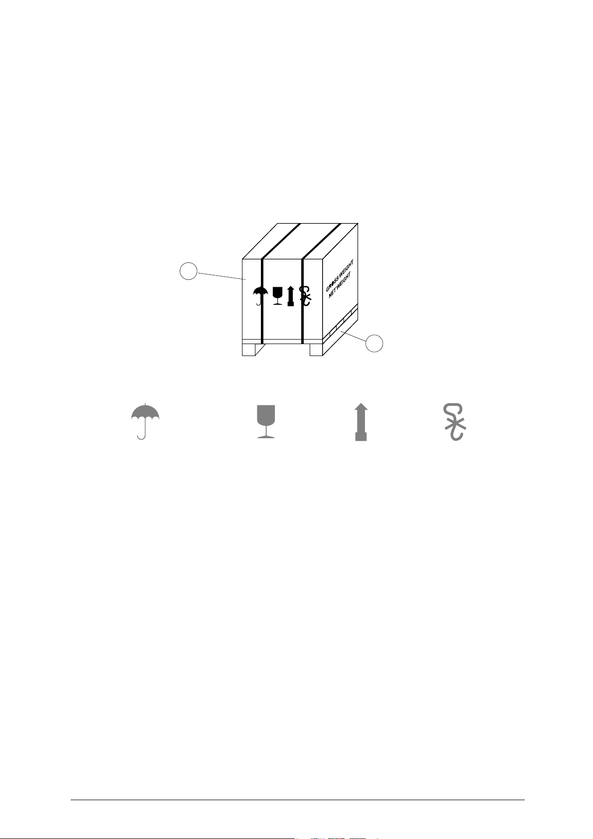
2.1 PACKING
The packing for
It comprises a pallet base (b) to which the machine is attached, and a cardboard box as a cover
The machine is fixed to the base of the pallet with screwed down brackets that hold it firm into place. This prevents the machine
and its protective shield from any damage
The closed packing is held in place by two straps which hold the cardboard box firmly on the pallet
Symbols are printed on the outside of the cardboard box to give instructions and warnings for transportation
Fig. 7
UNOCODE 399 PLUS
.
.
is designed to ensure safe transportation and to protect the machine and all its parts
(a).
.
.
.
To prevent any damage to the machine it is advisable to save and use the brackets provided for future transportation
.
10 Copyright Silca 2016
Page 15
Operating manual - English Unocode 399 PLUS
INCORRECT!
CORRECT
!
2.2 UNPACKING
To remove the machine from the packing box
1) cut the straps with scissors and remove
2) raise the top part of the cardboard box
3) loosen the screws, both on the front and back brackets that hold the machine to the pallet
4) use the special spanner (provided in the tool kit), to loosen the nuts on the machine’s feet
5) remove the metal brackets and re-tighten the nuts on the feet.
6) check the contents in the box, that should comprise with the following:
1 UNOCODE 399 PLUS
1
set of documents, including: an operating manual, a spare parts list and a guarantee
1
power supply cable
1
tool kit
Note: we strongly recommend you keep the packing intact for future transportation
2.3 MACHINE HANDLING
When the UNOCODE 399 PLUS has been unpacked, place it directly on its workbench; this operation
should be carried out by at least two people.
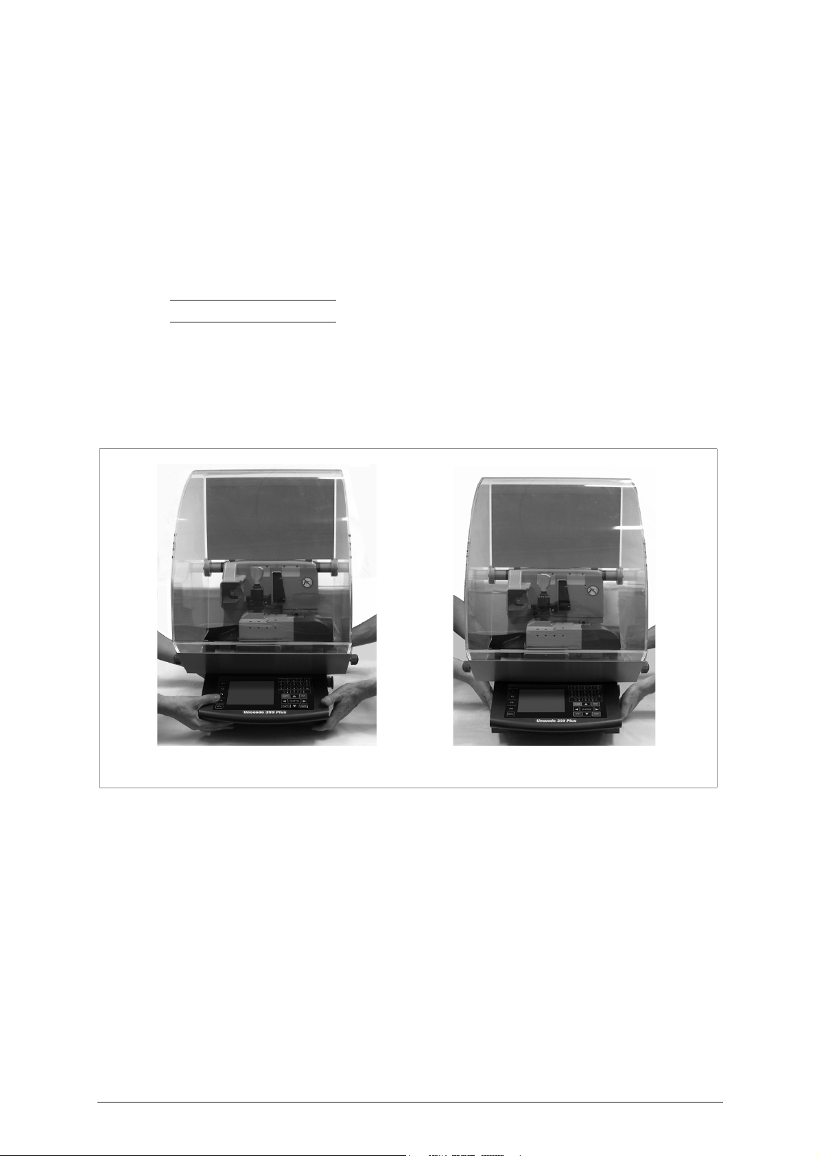
Take care to lift the machine firmly holding the base, and no other part.
ATTENTION: never lift the machine by holding the keyboard stand (fig. 8).
:
key-cutting machine
Fig. 8
Copyright Silca 2016 11
Page 16
Unocode 399 PLUS Operating manual - English
30 cm
30 cm
30 cm
100 cm
3 MACHINE INSTALLATION AND PREPARATION
The key-cutting machine can be installed by the purchaser and does not require any special skills.
It is supplied ready for use and does not need any special set up. However, the operator may have to control a few things before
operating the machine
3.1 CHECKING FOR DAMAGE
.
UNOCODE 399 PLUS
been carried out according to the instructions in this manual. However, it is always advisable to check that the machine has not
suffered any damage
is solid and compact and will not normally damage if transport, unpacking and installation have all
.
3.2 ENVIRONMENTAL CONDITIONS
To ensure that the best use is made of the key-cutting machine, it is important to place it in a well-aired area which is not too damp
The ideal conditions for the machine are
temperature between 10°C and
:
3.3 POSITIONING AND INSTALLATION
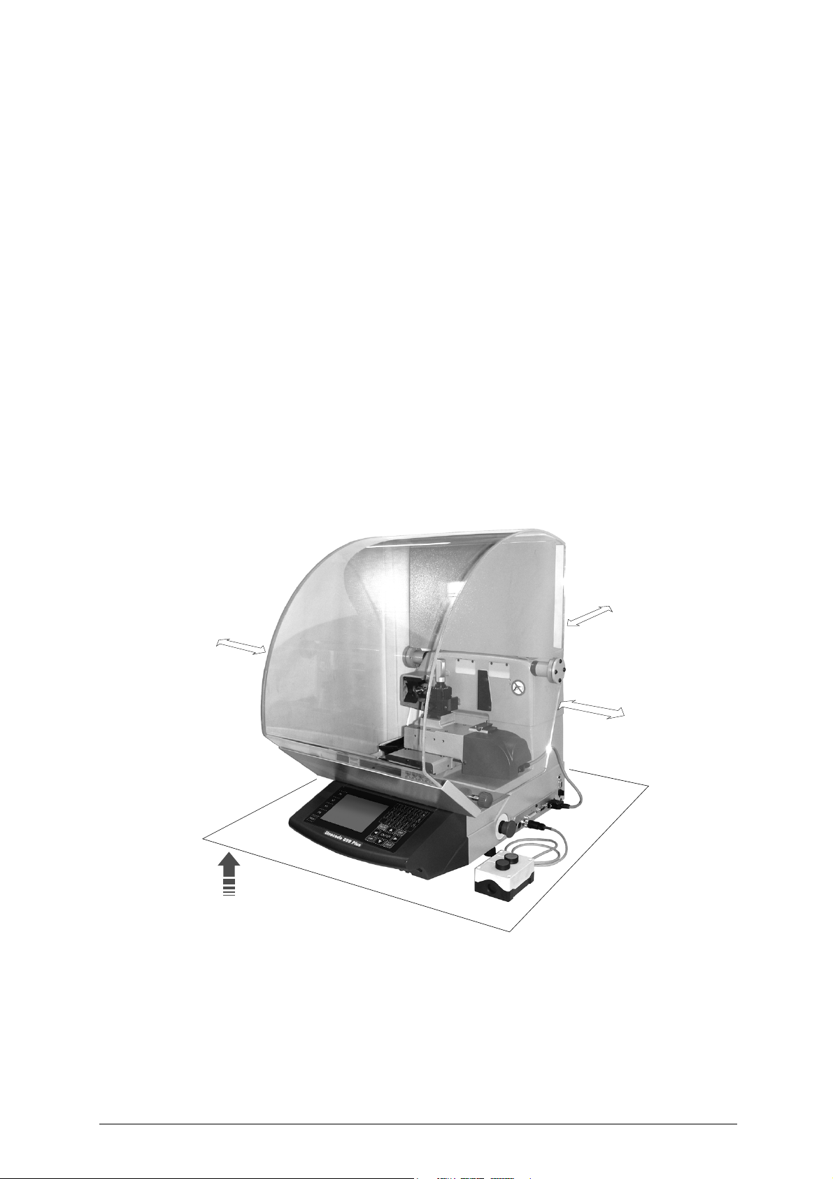
1) Place the machine on a horizontal surface, solid enough to support the weight of 51 Kg.
-
to work with ease, we suggest that the workbench be approximately the height of the operator’s hip
-
it is important to leave clearance of at least 30 cm behind the machine and on each side to ensure proper ventilation
2) Ensure that the machines voltage is the same as that of the mains power supply, which must be properly earthed and provided
with a differential switch.
3) Connect the power supply cable to the power supply socket.
40°C;
relative humidity: approx
.
60%
.
.
Fig. 9
12 Copyright Silca 2016
Page 17

Operating manual - English Unocode 399 PLUS
Do not use compressed air
for cleaning
3.4 DESCRIPTION OF WORK STATION
The machine needs only one operator, who has the following controls at his/her disposal
• master switch placed on the back of the machine
• key-positioning clamp
• keyboard
• display
• emergency button
3.5 GRAPHICS
• There is a prohibition warning label on the front side of the machine (fig. 10). This label must never be removed.
Fig. 10
(fig. 5, page 6):
Copyright Silca 2016 13
Page 18
Unocode 399 PLUS Operating manual - English
Clamp
V100
1
2
3
4
2
C
4
3
2
3
4
1
4
D
B
A
2
1
1
3
D side
C side
B side
A side
1
2
3
4
0
B
4
3
1
C
D
4
3
1
A
4
3
2
1
6
4 “SET UP” AND USE OF THE MACHINE
4.1 USE OF THE CLAMP
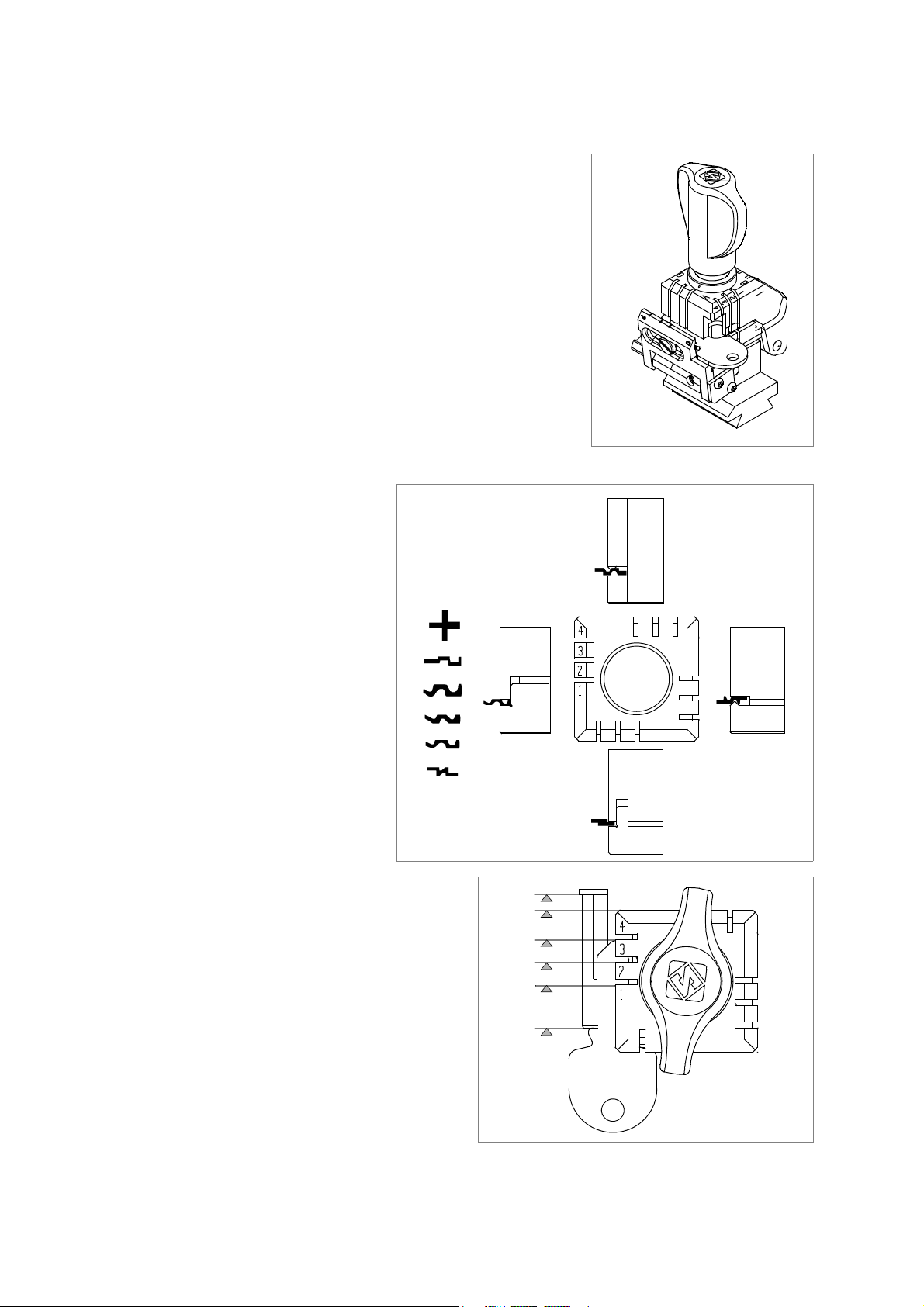
The four-sided clamp ensures excellent grip on the keys placed on their back or
profile sides
• Keys with 1 or 2 cuts should be fitted mainly on the A and/or B side of the
- The side of the clamp on which to
(fig. 12).
clamp.
Fig. 11
place the key is shown on the
machines display.
Fig. 12
Fig. 13 - key stops
14 Copyright Silca 2016
Page 19
Operating manual - English Unocode 399 PLUS
D5
E
Attention: the pin
should be placed
vertically
2
C
4
3
2
3
4
1
4
D
B
A
2
1
1
3
pin
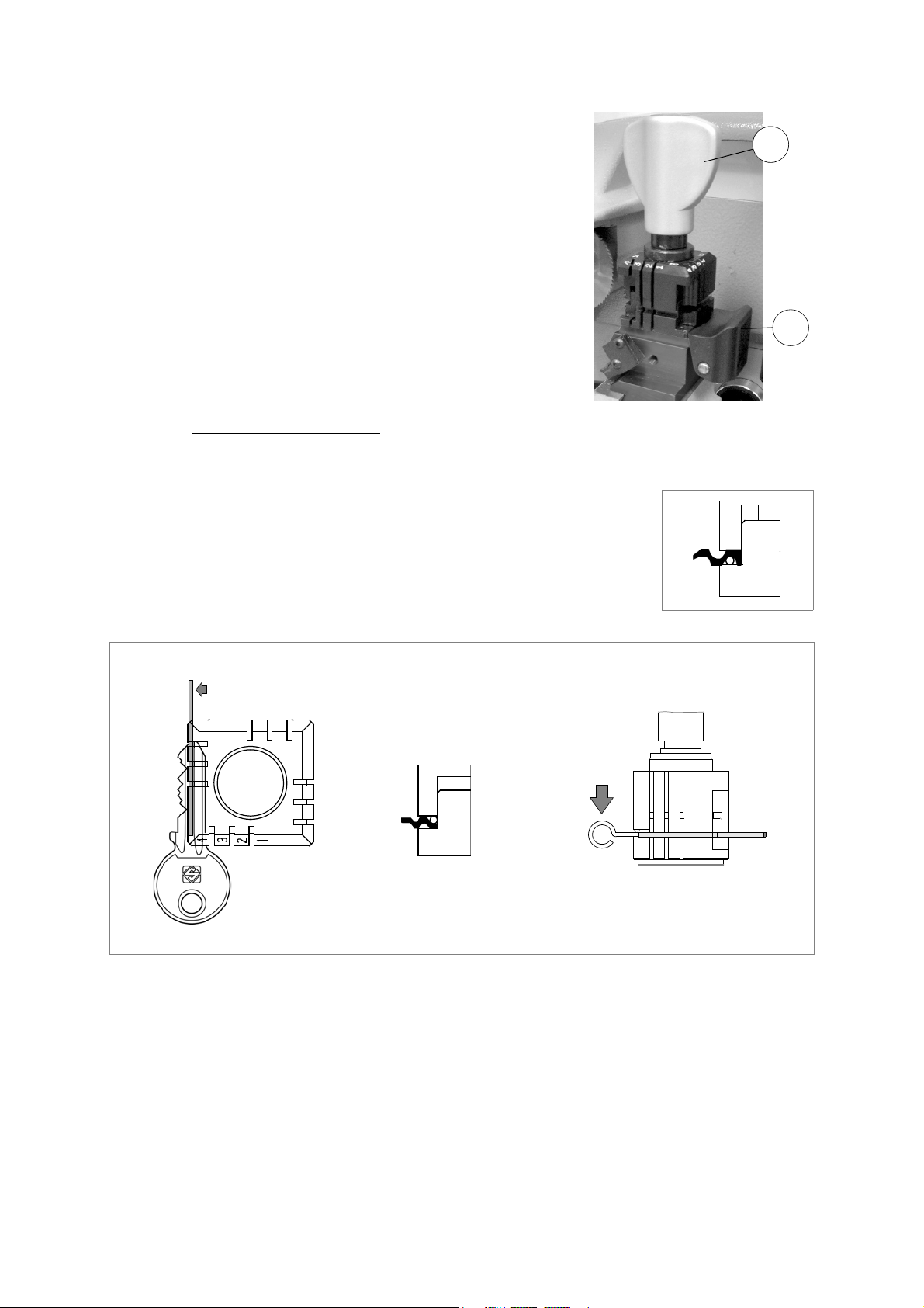
ATTENTION: the knob is gauged so that it do not exert too much
pressure for closing (if pressure is too high it only idles), which would
damage the key and the parts of the clamp (including the knob).
To turn the clamps:
With loosened handle (E) a light rotation of the clamp is sufficient
(gripping by the 2 jaws) to turn it to the required side. Alignment is
automatic and guaranteed by the mobile pressure device (D5) (fig. 14).
Fig. 14
Note: before starting to cut a key the V100 clamp gauge goes automatically to the idle position so there is no need to lower it.
U
SING PINS
Pins must be used in the case of keys with special profiles, to stop the keys
from moving and vibrating.
Fig. 16
Fig. 15
Copyright Silca 2016 15
Page 20
Unocode 399 PLUS Operating manual - English
D2
X1
X
i2
i
loosen
tighten
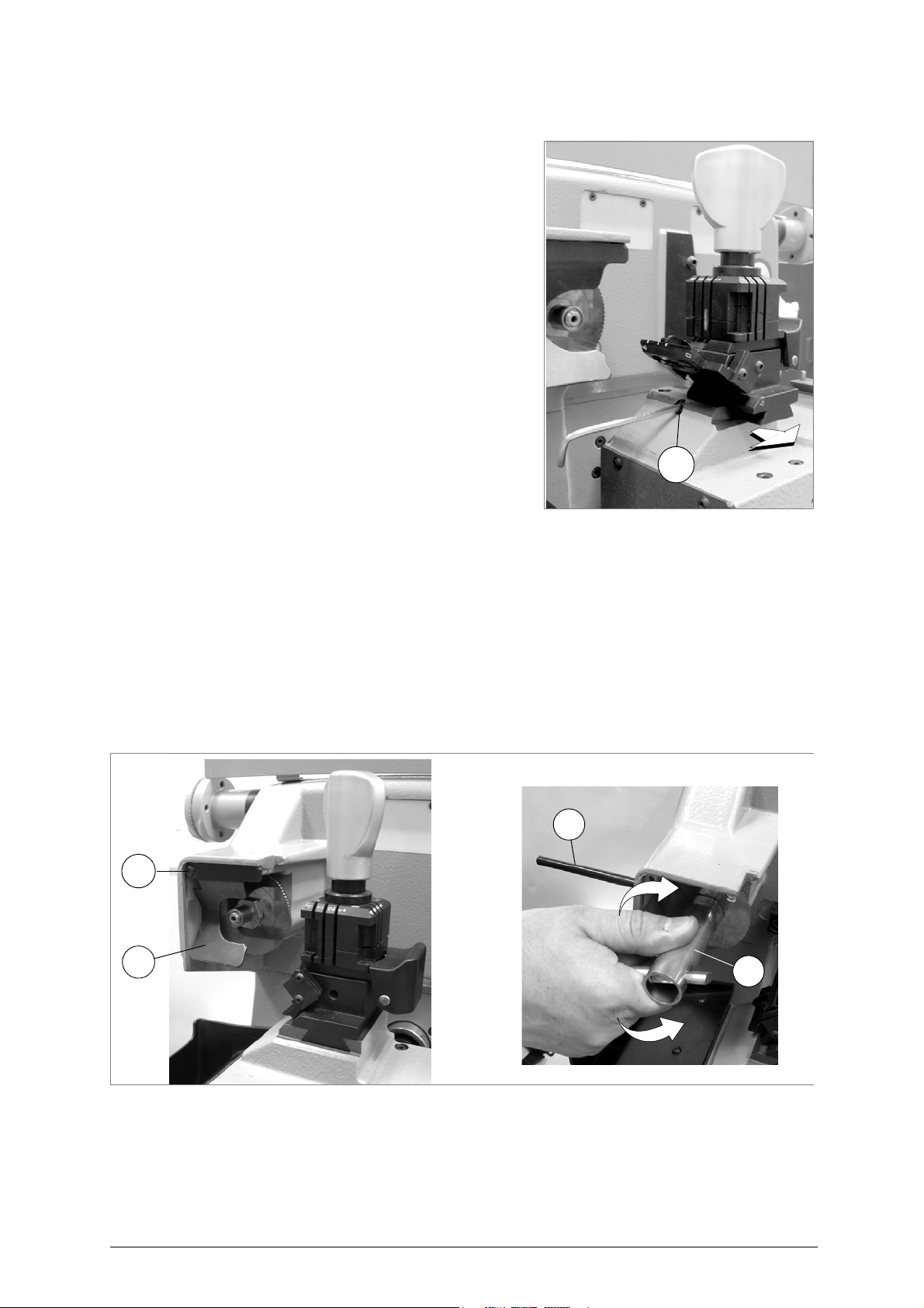
4.2 FITTING THE CLAMP TO THE MACHINE
To remove the clamp unit:
- loosen the grub screw (D2) (fig. 17) and slide the clamp out of the
dovetail guide.
To install the clamp unit on the machine:
- slide the clamp into the dovetail guide, pushing it all the way in,
then secure it by tightening the grub screw (D2).
These instructions refer exclusively to the standard
clamp (V100). For the use of optional clamps please
refer to the instructions provided along with them.
Fig. 17
4.3 CUTTER
The majority of keys utilize the standard cutter for code
cutting. Only in certain cases some special keys with particular type cuts require different cutters.
To change the cutter see chapter 4.4.
4.4 CHANGING THE CUTTER
1) raise the protective shield.
2) remove the cutter protective shield (i) by loosening the screw (i2).
3) slide the cutter release rod (X) into the hole located on the left side of the machines cutter shaft chassis (fig. 18).
4) loosen the cutter locking nut (turning it clockwise) with the19 mm socket wrench (X1) provided with the machine.
ATTENTION: the thread is left-handed.
5) replace the cutter, then tighten the nut (turning it anticlockwise) and remove the rod from its hole.
6) place the cutters protective shield (i) back into position securing it with the screw (i2).
Fig. 18
ATTENTION: when replacing a worn cutter with a new one or with a re-sharpened cutter consult chap.5.7 "GAUGING", page
40.
16 Copyright Silca 2016
Page 21
Operating manual - English Unocode 399 PLUS
5 OPERATING GUIDE
Introduction
The Operating Guide below explains how to use the UNOCODE 399 PLUS without a Personal
Computer.
All operations to manually use the key-cutting machine are explained step by step.
The programs available for Personal Computers connected to the key-cutting machine are able to
transmit data for cutting.
Programs for Personal Computer eliminate manual procedures of certain functions, once the data has
been transmitted to the machine it bypasses some of the operating guides screens.
If UNOCODE 399 PLUS is used with a PC, exclude the manual mode pages when consulting the
operator’s handbook.
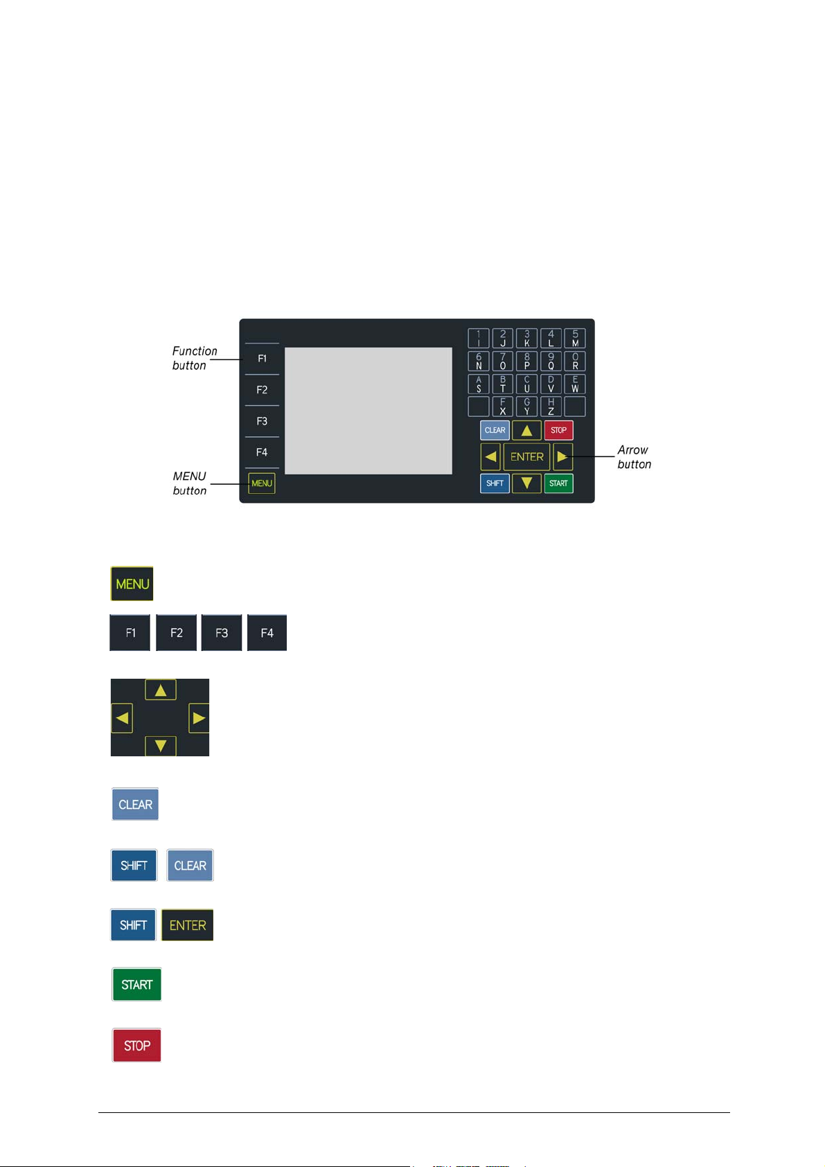
5.1 ON-BOARD KEYPAD AND FUNCTIONS
Fig. 19
The MENU key is used to view the list of main functions:
MENU key: is always active from any of the windows.
Function keys: select the on-screen options
Arrow keys: used to move the pointer (navigation) in the on-screen fields
CLEAR: used to delete a single character
SHIFT+ CLEAR: pressed together to delete an entire row
SHIFT+ ENTER: pressed together to insert a digit space
START: starts the procedure
STOP: cancels the operation and/or returns to the previous menu.
Copyright Silca 2016 17
Page 22
Unocode 399 PLUS Operating manual - English
5.2 PRELIMINARY OPERATIONS
1) place the key-cutting machine on the work top.
2) connect the power lead to the mains (cap.3.3, page 12).
3) make sure that the emergency button (N, fig. 5, page 6) is not turned on.
4) turn the machine on by means of the main switch (A, fig. 5, page 6) that is located on the back of the machine.
- to check or edit the parameters for using the machine, access the OPTIONS menu (chap.5.9, page 52).
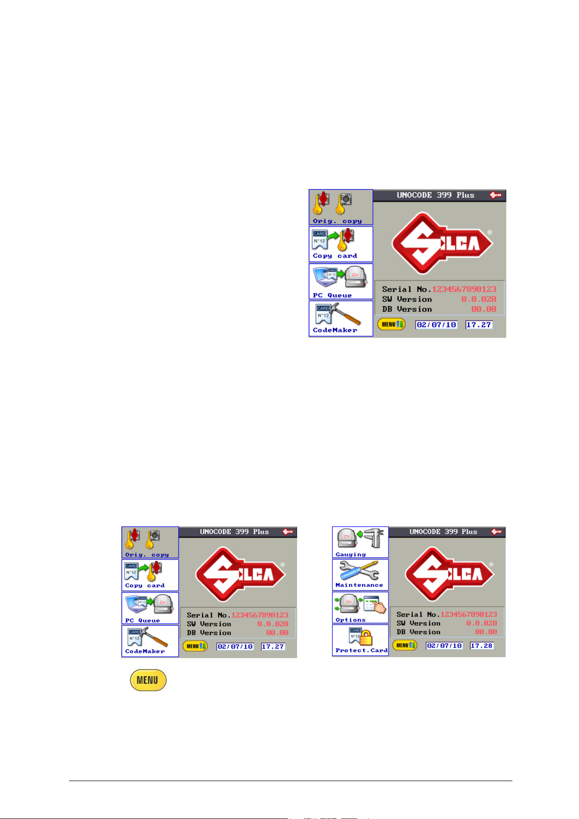
- set the required measuring unit (default is MILLIMETRES)
5) When the machine is turned on the display shows the following screen:
The main screen will show:
• Main functions
• Name of the key-cutting machine
• Serial number of the key-cutting machine
• SW version: machine program version
• DB version: version of the cutting card
Database on board the machine
•Date
•Time
• MENU word (flashing)
MAIN MENU FUNCTIONS
• Copy from Original (FUNCTION NOT ON THIS MACHINE)
• Copy card
•PC queue
• CODEMAKER
• Gauging
• Maintenance
• Options
• Enabling
Fig. 20
Press the MENU key to view the list of icons relating to the main functions of the
machine program.
18 Copyright Silca 2016
Page 23
Operating manual - English Unocode 399 PLUS
cutting angle
cutting space
flare (base of the cut)
depth
F1
F3
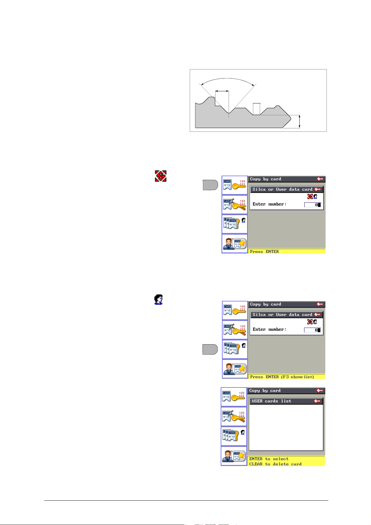
5.3 COPY BY DATA CARD
The Copy by Data Card function is used to cut a key using the “origin al” parameters memorized by
Silca or the operator (USER data card and CODEMAKER data card).
Part of the machine memory is used for
storing data cards.
A data card is a database of “Spaces”,
“Depths”, “Cutting angles” and “Flares” for
all the keys taken into consideration by
Silca.
Figura 21
From the initial screen press F2 to use the function and then:
•Key F1 to access the SILCA and USER data cards.
•Key
F2
to access the CODEMAKER data cards.
• SILCA data cards
References to “SILCA data cards” are found in:
- Silca paper catalogues
- Silca electronic catalogue
- Silca Key Programs
SILCA data cards can be edited for certain
parameters only. Variations CANNOT BE SAVED in
the machine memory.
The number of SILCA data cards increases periodically,
with “Silca Code Program” updates that the user can
purchase separately. Through the Silca Code Program
the user can update the program and the on-board
machine data.
• USER data cards
This is a data card customized by the user with
Silca Key Programs on a PC and sent to the
machine. It may be:
- created by the SKP Code Maker
- a Silca SKP data card with certain parameters edited.
USER data cards can be edited for certain
parameters only. Variations CAN BE SAVED in the
machine memory.
• Press F3 to view the list of USER data cards.
Copyright Silca 2016 19
Page 24
Unocode 399 PLUS Operating manual - English
F2
F3
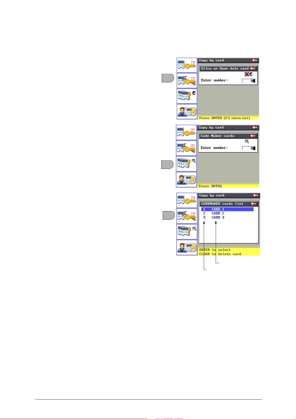
F2
Nr. Scheda CodeMaker
Description
• CODEMAKER data card:
Data card customized by the user, created with the CODEMAKER function on the machine (see
cap.5.6, page 36).
• From the initial screen “Copy by data card” press F2
• Enter the CODEMAKER data card number or press F3
to see the list of CodeMaker data cards (chap.5.6, page
36).
20 Copyright Silca 2016
Page 25
Operating manual - English Unocode 399 PLUS
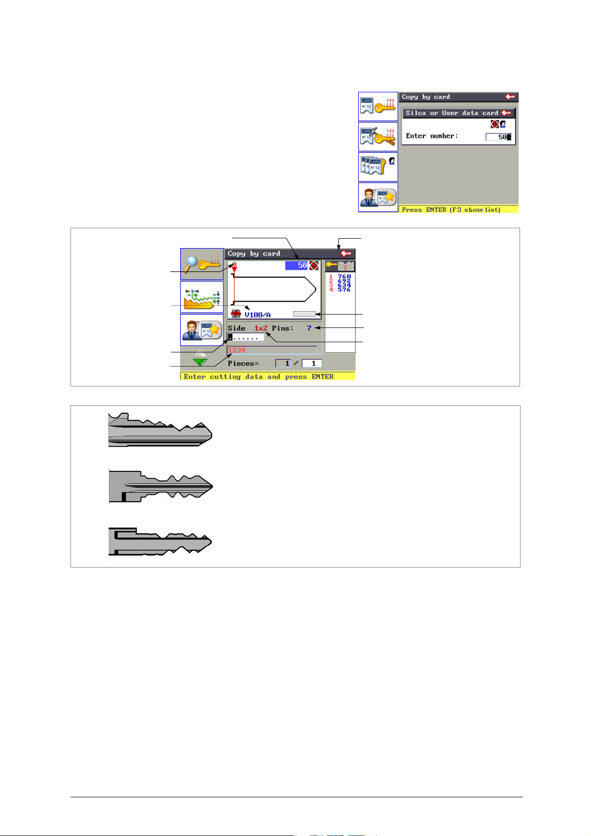
Card No
Number of cuts per side for current key
cut entry field
Symbols associated to cutting depths
symbols allowed for data
Adapter* (if required)
Clamp to use
Side 1: single cut
Side 1x2: double symmetrical cuts
Side 1 / Side 2: double asymmetrical cuts
Key Stop
Side 1
Side 1 x 2
Side 1 / Side 2
Single cut
Double symmetrical cuts
Double asymmetrical cuts
“Copy by data Card” procedure
1) Digit the card number (e.g.: 50):
2) Press ENTER:
Fig. 22
Fig. 23
(*) Adapter
on certain data cards provided by Silca the parameter “Adapt: B...” indicates the type of accessory
needed to cut a key.
3) Digit the cuts.
In the cut entry field:
- The dots shown represent possible cuts. The same card can be used for a number of keys with a different number of cuts.
- If the key needs fewer cuts than the dots on display, just enter the partial combination (from left to right).
- in the case of
double asymmetrical cuts
, enter the cuts for both fields involved.
4) Press ENTER.
Copyright Silca 2016 21
Page 26
Unocode 399 PLUS Operating manual - English
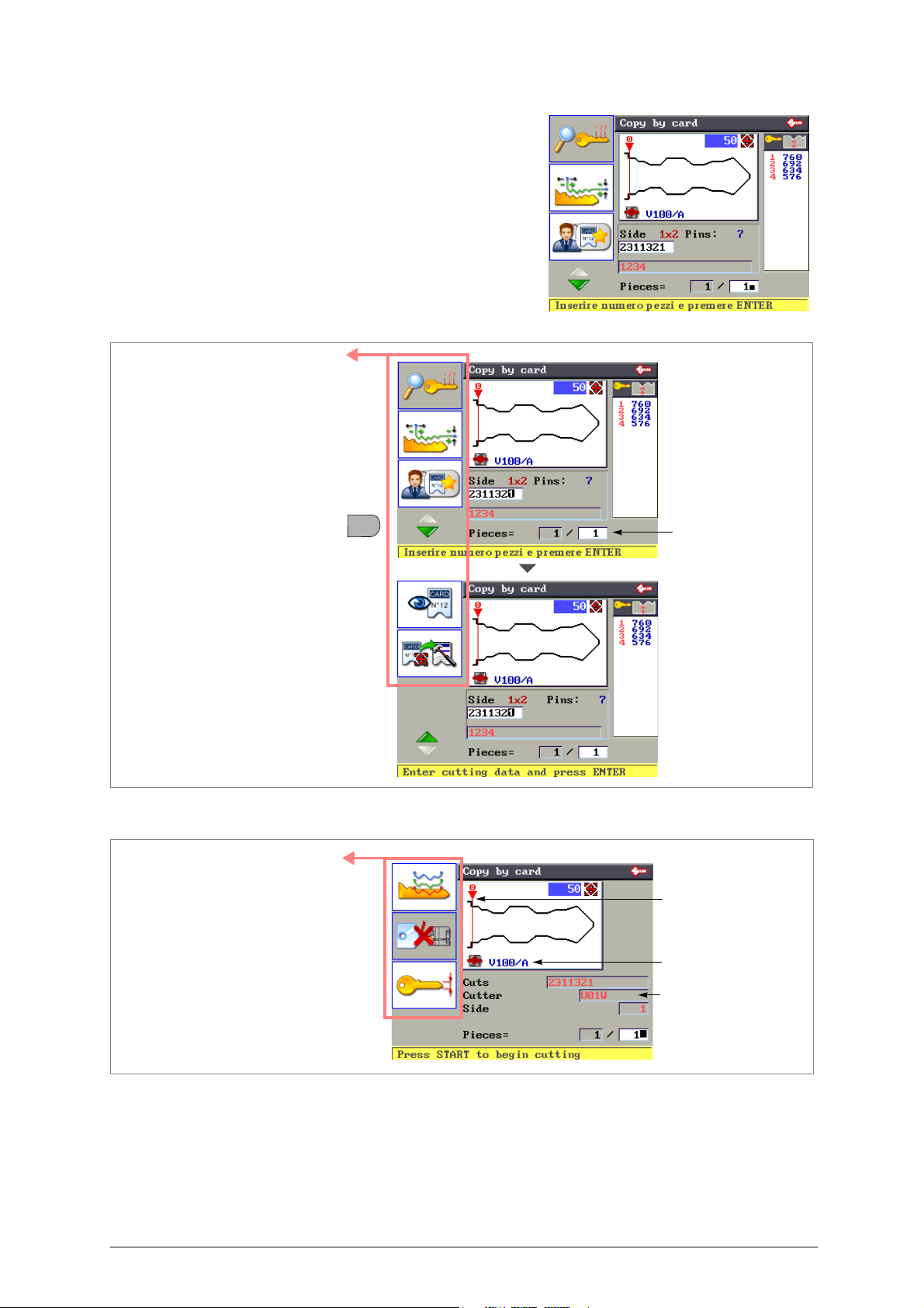
number of pieces
a
b
c
d
e
F4
Accessory functions
(chap.5.3.2, page 25)
to cut
Press F4 to view all the functions
cutter to use
key stop: Stop 0
f
g
h
clamp to use
Accessory functions
(chap.5.3.2, page 25)
5) Enter the quantity of keys to be cut (max.999)
Fig. 24
Fig. 25
6) Press ENTER.
• Check that the clamp is the right one (e.g. V100 Side A)
• Install the key blank with the required reference (e.g. Stop 0).
• Check that the installed cutter is the right one (e.g. U01W - standard).
Cutters:
the standard universal cutter U01W (e.g. key FO21P).
To replace the cutter follow the instructions given in chap.7.3, page 65.
some data cards available in the machine memory require the use of tools different from
22 Copyright Silca 2016
Page 27
Operating manual - English Unocode 399 PLUS
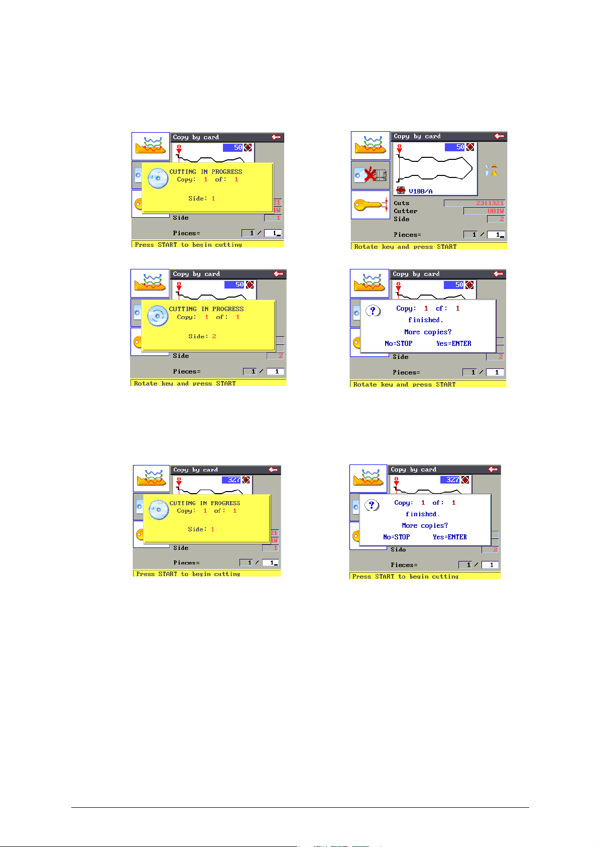
7) Press START.
TO CUT ON BOTH SIDES:
- Turn the key and cut the second side if the key is symmetrical, as in this case. Press START.
8) Press STOP and remove the key.
TO CUT ON ONE SIDE:
- Press STOP and remove the key.
Copyright Silca 2016 23
Page 28
Unocode 399 PLUS Operating manual - English
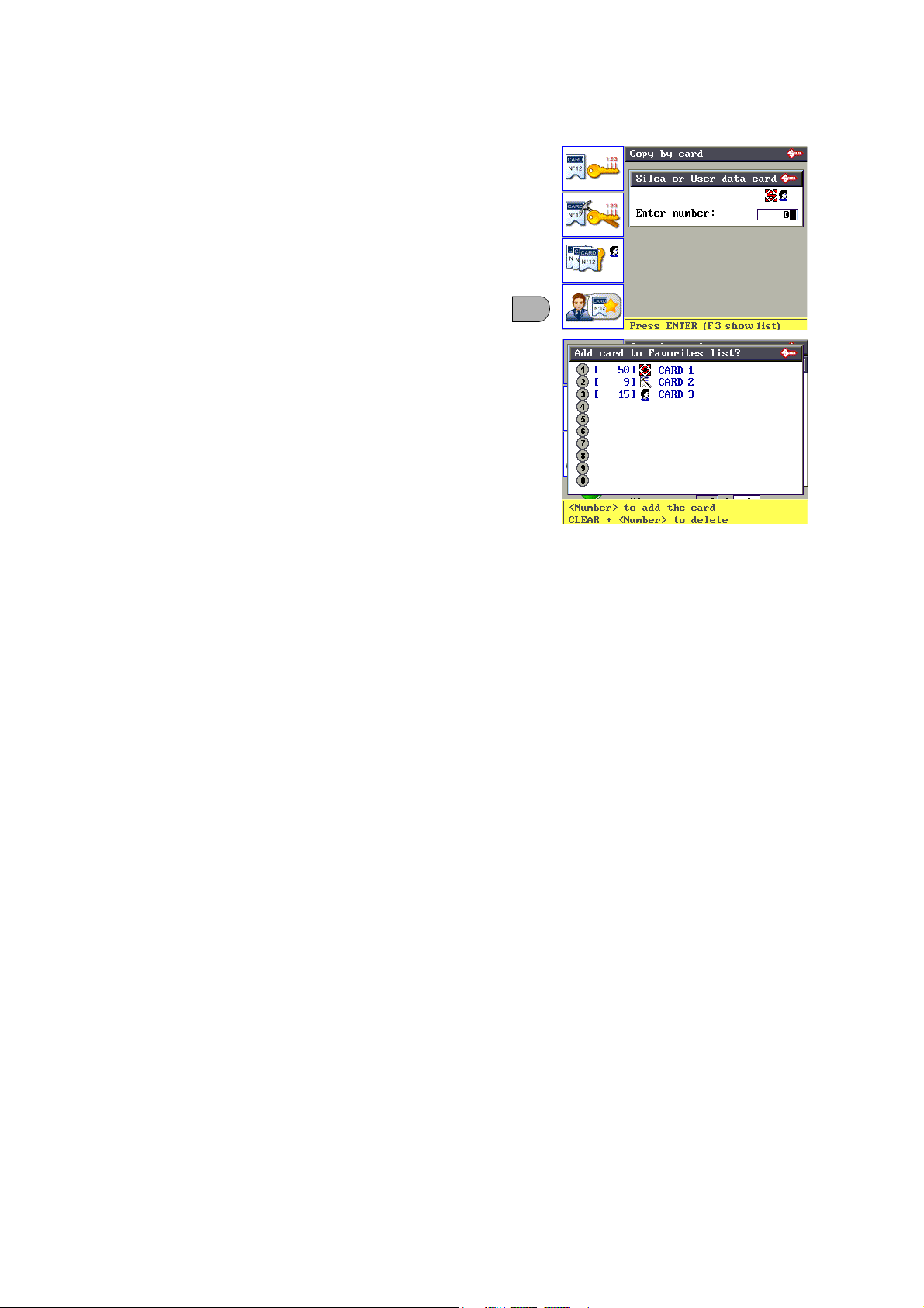
F4
5.3.1 FAVOURITE DATA CARDS
Frequently used data cards (SILCA, USER or
CODEMAKER data cards), saved in the
Favourites menu (chap.5.3.2 "ACCESSORY
FUNCTIONS FOR “COPY BY DATA CARD”",
page 25).
From the initial screen “Copy by data card”,
press F4 to view the list of Favourite data cards.
Enter the number of the required data card to
start the “Copy by Data Card” function.
24 Copyright Silca 2016
Page 29
Operating manual - English Unocode 399 PLUS
F1
F2
cutting angle
cutting spaces
flare (base of the cut)
cutting
depths
F3
F2
F1
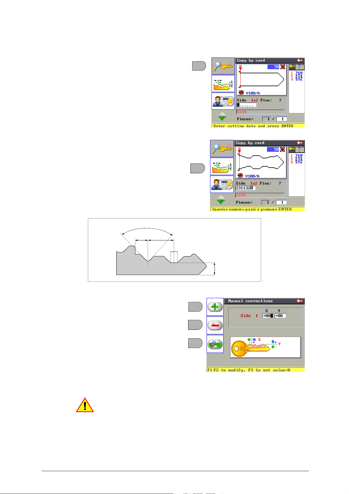
5.3.2 ACCESSORY FUNCTIONS FOR “COPY BY DATA CARD”
a) Data Card Decoding
FUNCTION NOT AVAILABLE ON THIS MACHINE
b) Manual Adjustments
• Press F2 to set manual adjustment to cutting depths
and spaces.
Figura 26
• Press F1 to obtain positive values (+).
• Press F2 to obtain negative values (-).
• Press F3 to cancel the settings.
Y depth adjustment (from -30 to +30 hundredths
of a mm):
- Y positive value: raise the cuts
- Y negative value: lower the cuts
X space adjustment (from -30 to +30 hundredths
of a mm):
- X positive value: move cuts to the right of the stop
- X negative value: move cuts to the left of the stop
This symbol appears in Copy by
Data Card when manual adjustments have been made.
Copyright Silca 2016 25
Page 30
Unocode 399 PLUS Operating manual - English
F3
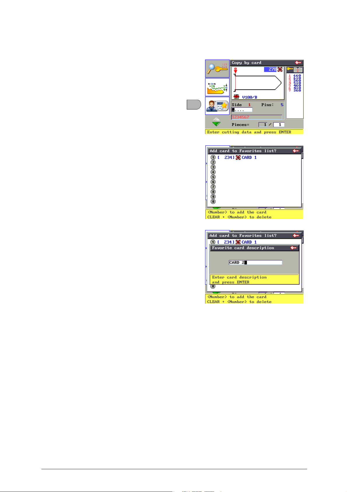
c) Save Data Cards in the Favourites menu
Press F3 to save in the Favourites Menu
- a SILCA data card
- a USER data card
- a CODEMAKER data card
From the keyboard digit a number from 1 to 0
to assign a position to the data card to be
saved.
If all the numbers are taken, re-use an
existing position
:
• Enter the data card description.
• Press ENTER, which takes you back to the initial
screen “Copy by Data Card”.
26 Copyright Silca 2016
Page 31
Operating manual - English Unocode 399 PLUS
F1
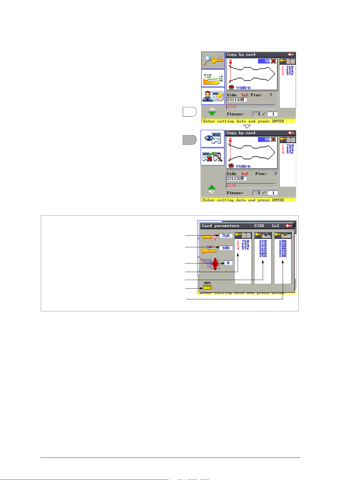
F4
Key blank measurements
*
Cutting angle
Symbols associated to cutting depths
*
Cutting spaces
*
Base of the cuts
*
Key stop
Measuring unit
d) Data Card Parameters
Function used to view the technical data
relating to the data card.
•Press F4.
•Press F1.
• Press STOP to exit.
(*) With the measuring unit set on millimetres the highlighted measurements are expressed in
hundredths of a millimetre.
Copyright Silca 2016 27
Page 32
Unocode 399 PLUS Operating manual - English
F2
F4
F2
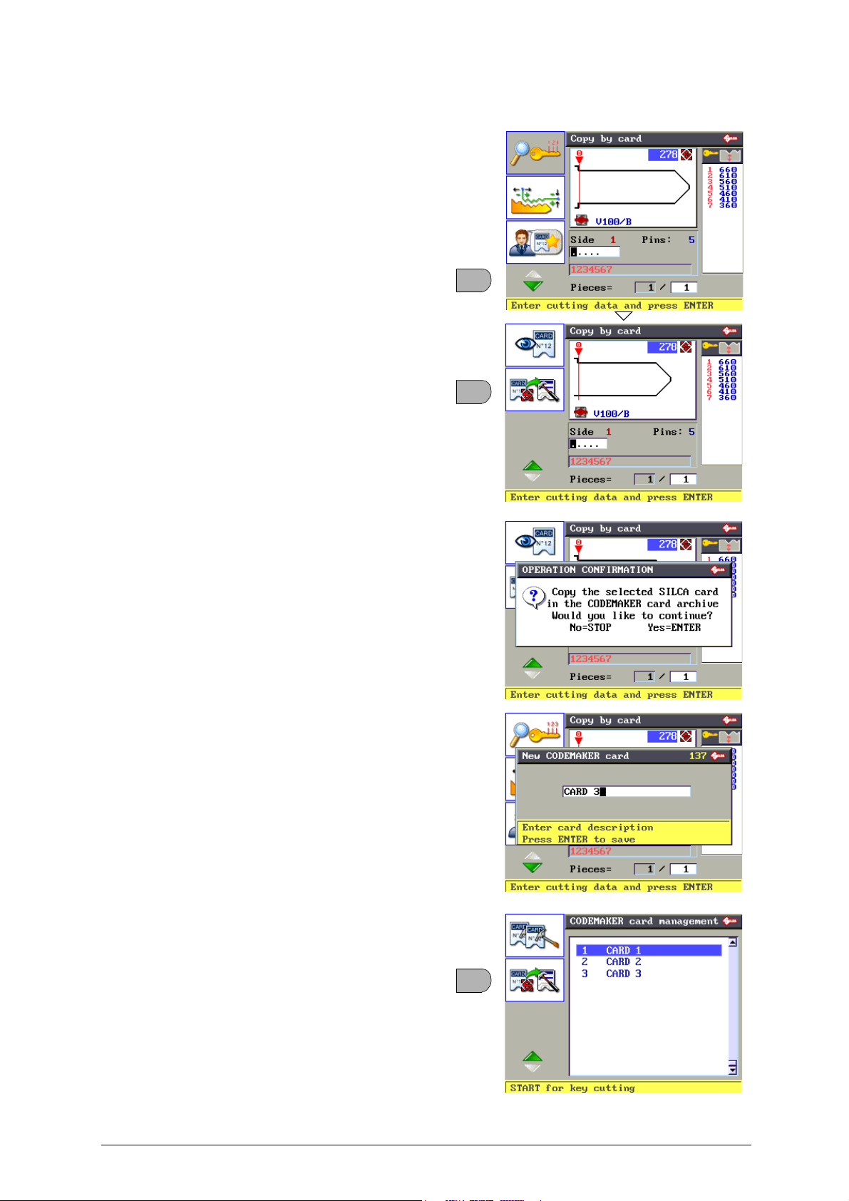
e)
Copy SILCA Data Card in
Function used to copy a SILCA data card
into CODEMAKER and edit some of the
parameters.
•
Press
F4.
•
Press
F2.
CODEMAKER
ATTENTION:not all SILCA data cards
can be copied into CODEMAKER. If
there is no icon shown the data card in
question cannot be copied ( due to no ncompatible data).
•Press ENTER.
•Press ENTER.
• Enter a description of the data card.
•Press ENTER.
The “Copy SILCA Data Card” function can
also be used in CODEMAKER through the
CODEMAKER function.
28 Copyright Silca 2016
Page 33
Operating manual - English Unocode 399 PLUS
N
P
L
V
V
F1
Current cut type
Cut type set by Silca
as original
Feasible and selectable
options for the
selected card
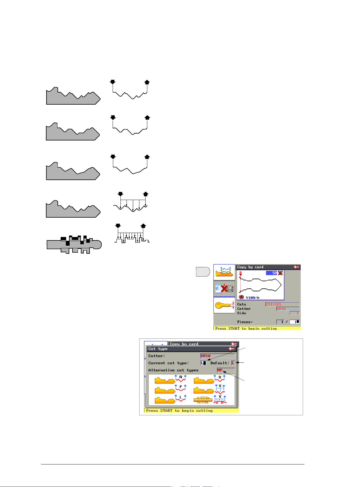
f) Edit the Cutting Method
• Type of Cut
The machine can run several types of cut: NORMALE, PIANO, LASER, VERTICALE.
If provided for on the data card, the user can edit the type set by default.
N
ORMAL
For conventional car and door keys.
F
LAT
Mainly used for car keys where the cut edges are rounded to facilitate the
movement of the blades when the key is put into the lock.
L
ASER
Conjunction of the cutting angles is determined automatically
by the machine, allowing cuts to be made with variable angles;
this facilitates the smooth entry of the key into the lock,
prolonging the working life of the key.
V
ERTICAL
Necessary for special keys with small bits (Silca art. FO19P,
FO21P...) where a special cutter is required.
When this cutting method is used a special angled cutter is
needed.
• Press F1 to view the type of cut set by Silca for the data
card and the possible alternatives (if applicable).
Edit the set type of cut with
one of the alternatives
given.
The type of cut is active
throughout the time the
machine is in use.
When the machine is
turned off the function
returns automatically to
the original setting for the
type of cut.
ATTENTION: for certain cutting methods the standard cutter U01W must be replaced with a specific cutter.
Copyright Silca 2016 29
Page 34
Unocode 399 PLUS Operating manual - English
F2
Key Blank
measurement
F3
g) Electric Contact
FUNCTION NOT AVAILABLE ON THIS MACHINE
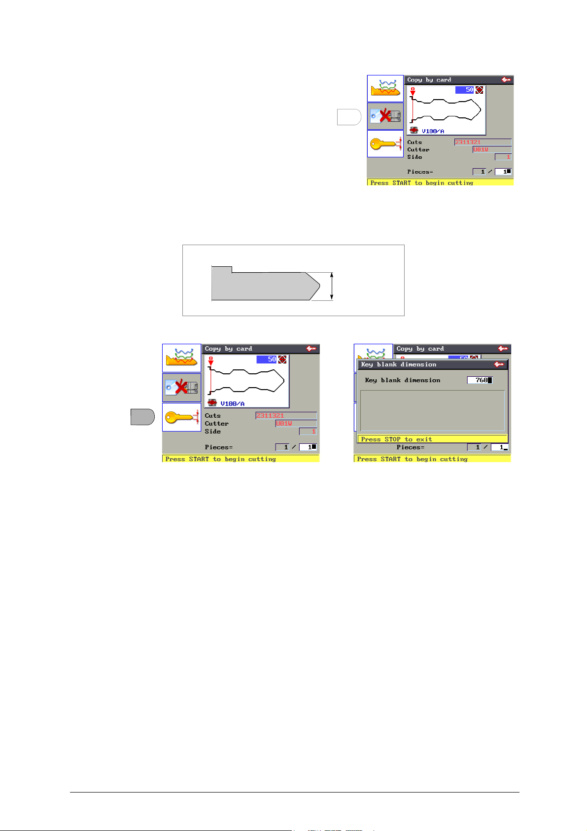
h) Key Blank Measurement
Function used to edit the key blank measurement.
The key blank figure in the database refers to a key produced by Silca.
Figura 27
1) Press F3 to vary the set measurement for the key blank to be cut.
2) Enter the required measurement and press ENTER to save.
3) Press STOP to quit.
30 Copyright Silca 2016
Page 35
Operating manual - English Unocode 399 PLUS
8
8
6
04
?
8
8
6
04
5.4 SPECIAL CASES
5.4.1 CUTS NOT ALLOWED
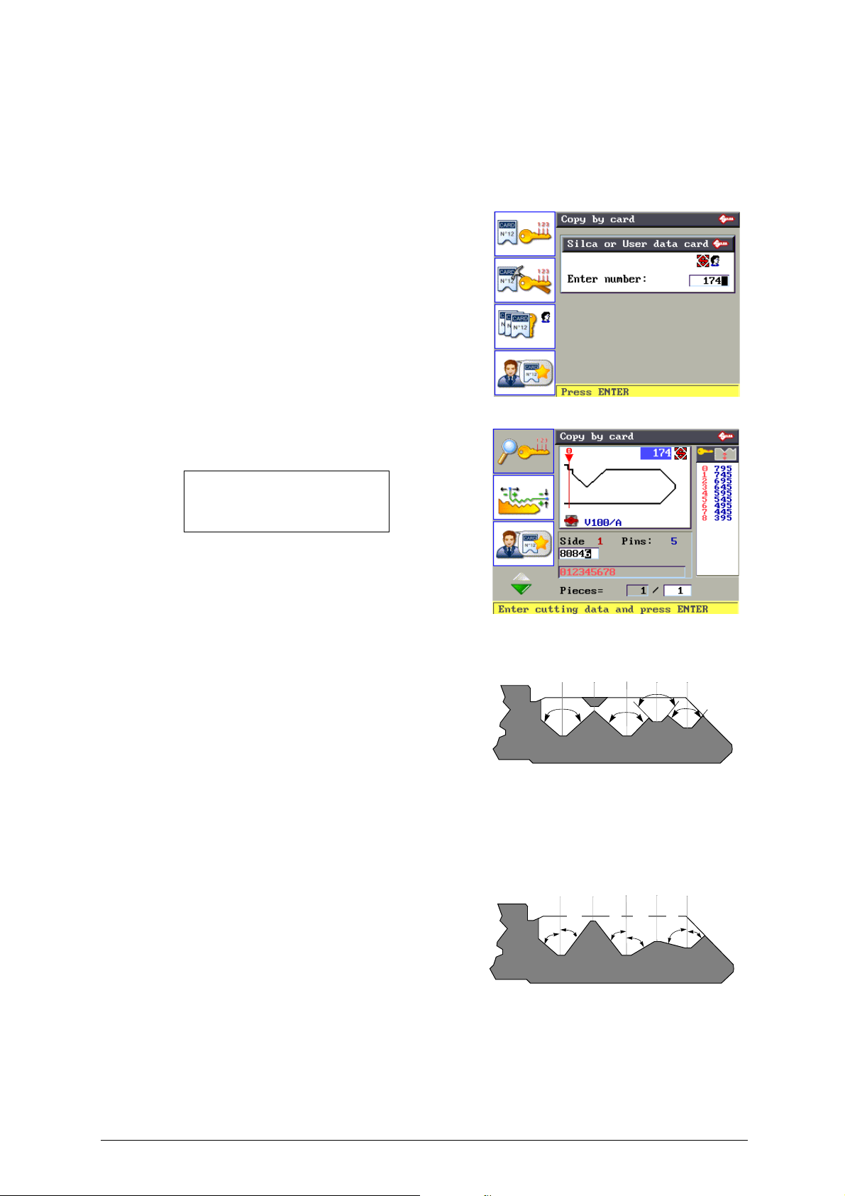
When the machine is used manually with certain data cards, it may not be possible to carry out certain
entered combinations. This happens when the cutting depths are not compatible in the order the user
entered the possible cuts.
Example:
1) Enter data card number
2) Press ENTER
3) Enter the cut
4) Press ENTER
The Silca software calculates the validity of the data
entered. If they are not congruous the following
message will appear:
NON-FEASIBLE
COMBINATION
This message is explained below.
The reason for the conflict between certain cuts is
explained simply in the case shown.
With regard to the cut that originated the message
<NON-FEASIBLE COMBINATION> it can be seen
that between the two deep cuts (8) and the consta nt
angle (100°) the intermediate cut (0) would be
removed.
This happens when the cutting angle N (Normal) is
not made variable by means of the type of cut L
(Laser).
The new drawing of the key shows how for the same
cutting process (80846) the cutting angles are
automatically calculated by the conjunction of the
cutting base with a straight line.
This aspect, admissible with certain car keys, is more
commonly known as ‘the ideal cutting line’.
ATTENTION: in this example it can be seen that the ß angle is
less than 45°. This could cause serious problems with a lock,
making it difficult or impossible to place the key into the cylinder
or remove it.
Fig. 28
Control of the combinations in the Options menu can in any case be disabled (Cutting check cap.5.9).
Copyright Silca 2016 31
Fig. 29
Page 36
Unocode 399 PLUS Operating manual - English
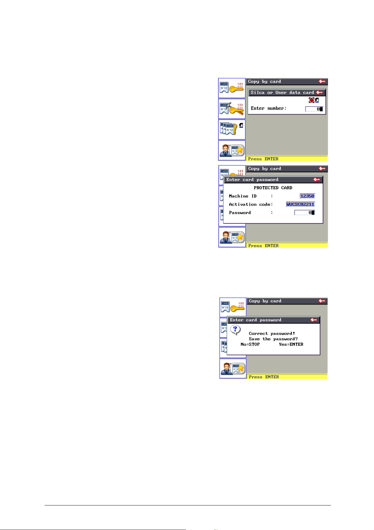
5.4.2 LIMITED ACCESS TO DATA (PROTECTED SYSTEMS)
Silca has limited access to some of the data in the Database in agreement with certain ma nufacturers.
Limitations are applied to:
-
DATA CARD
To access protected data:
a) apply to the manufacturer for authorization.
b) communicate to Silca:
Silca will issue a Password to enter in order to enable
cutting of the protected system.
When a protected data card is selected from the F1
menu (e.g.: 2211) the following screen will appear:
When the manufacturer’s authorization has been
given, contact SILCA to be issued a password,
providing the following information:
- Machine serial No XXXXXXXXXXXXX
Read the serial number on the ID plate located on
the back of the key-cutting machine or on the initial
display.
- Machine ID XXXXX
Can be seen in the box used to apply for the
password.
- ACTIVATION Code XXXXXXXXXX
ONLY shown when access is tried to protected data.
, if the key-cutting card is protected, access is denied.
- cutting machine SERIAL NUMBER
- cutting machine ID
- the ACTIVATION CODE
Enter the password issued by Silca into the relevant
field.
If the password entered is correct, the following
screen will appear:
• The password can be saved (with ENTER) so that it will not
be necessary to enter it again when using the protected data
card.
• Press STOP if you don’t want to save the password in the
machine memory. In any case the choice made is enabled for
the operation in progress.
The password will be required again for future access to the data card.
PROTECTED DATA CARD ENABLING PROCEDURE
1) Enter the data card number.
2) Press ENTER.
3) Enter the Password.
4) Press ENTER.
5) Press ENTER again to confirm.
32 Copyright Silca 2016
Page 37
Operating manual - English Unocode 399 PLUS
Card No. Pieces
No. jobs received
Indirect codes
F1
F2
5.5 PC QUEUE FUNCTION
U
SING THE MACHINE WITH A
The “Silca Code Program” is used to make various searches by cutting code and store them in a
special job queue (or file).
This special function is designed to assist operators who wish to work with a number of simultaneous
searches. After making the required searches by code, just file them in this special job queue then
transfer them all together onto UNOCODE 399 PLUS.
The information transmitted by the PC is read only files and cannot be edited manual ly (except for
“Key blank measurement”). Each line transmitted corresponds to a cutting stage for one or more keys.
For each cut transmitted the number of pieces to produce is set. When the set number of pieces has
been completed, a “+” sign will indicate that the cycle is finished.
Should a work queue be interrupted, turn off the UNOCODE 399 PLUS. When the machine is turned
on again and the <PC queue> is called up, the list reappears, starting from the first line.
To enable the function press F3 from the initial screen.
• PC queue
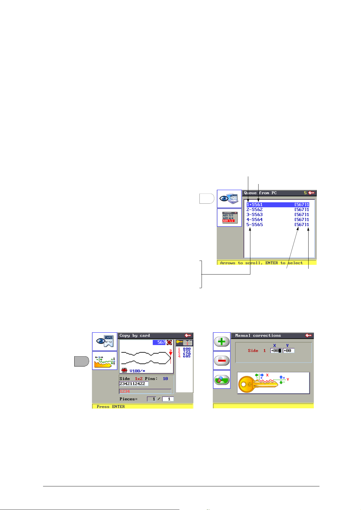
The data received from the PC are given in the form of a list, e.g:
- Number of jobs received
- Indirect cutting code
- Number of Silca data card used
- Number of pieces to cut
PC
Use F1 to view the data relating to the job
selected.
PROCEDURE:
1) Select the job to be done and press ENTER.
• A “+” sign indicates that the job HAS BEEN
COMPLETED.
• A “-” sign indicates that the job HAS NOT
BEEN COMPLETED.
The job data received from the PC program CANNOT be edited manually (except for “Key blank
measurement”).
For example, the following will appear on the display:
• Press F2 to view any manual adjustments set by the PC program.
2) Press ENTER to continue:
Copyright Silca 2016 33
Page 38
Unocode 399 PLUS Operating manual - English
F1
F3
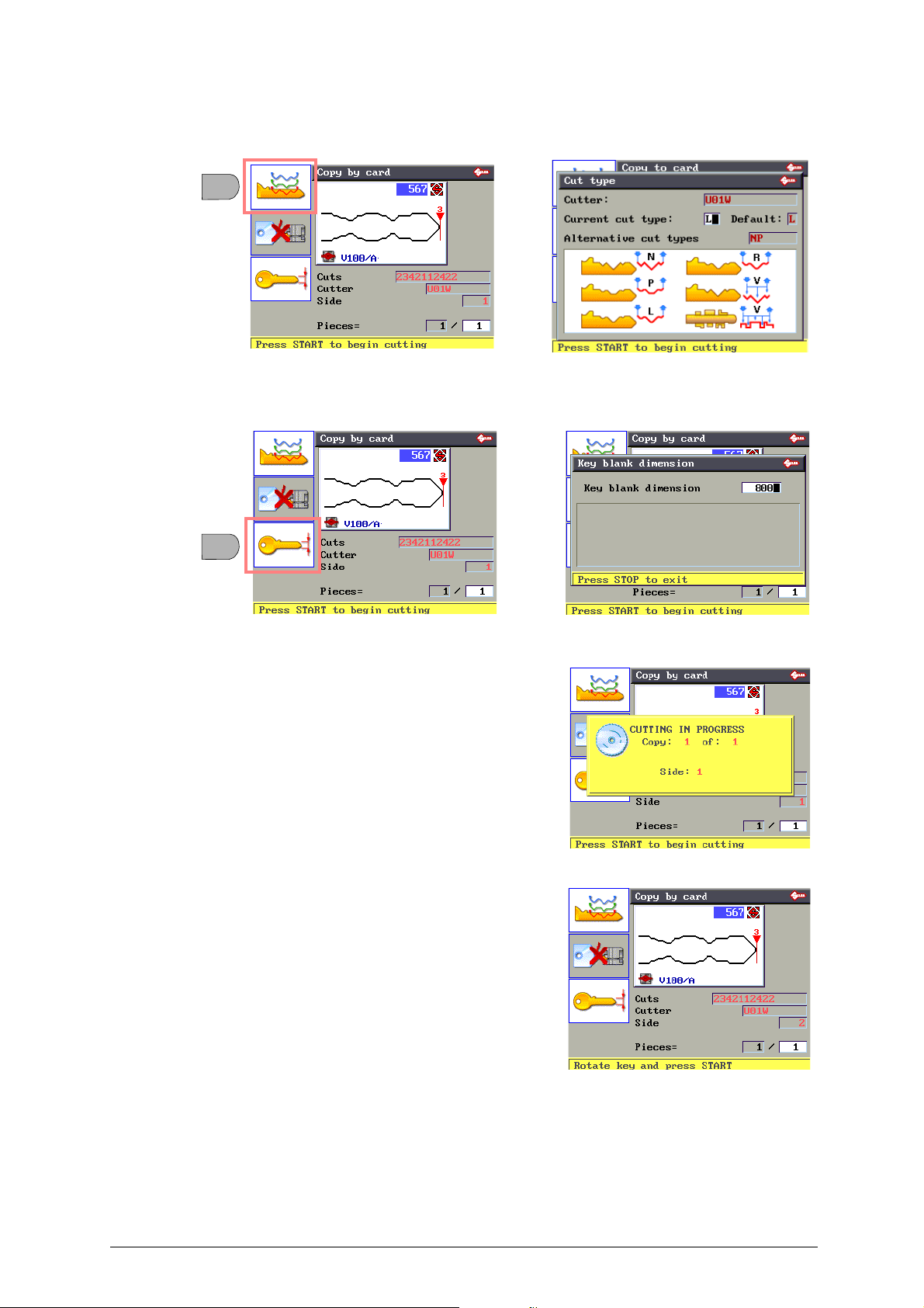
“CUTTING METHOD” Accessory Function
• Press F1 to view the CUTTING METHOD set by Silca for the data card involved.
“KEY BLANK MEASUREMENT” Accessory Function
• Press F3 to alter the setting for the measurement of the key blank to be cut.
3) Insert the key blank in the clamp on the cutter side.
4) Press START. Cutting starts and the display will show:
When the first side has been cut, the display will show:
34 Copyright Silca 2016
Page 39
Operating manual - English Unocode 399 PLUS
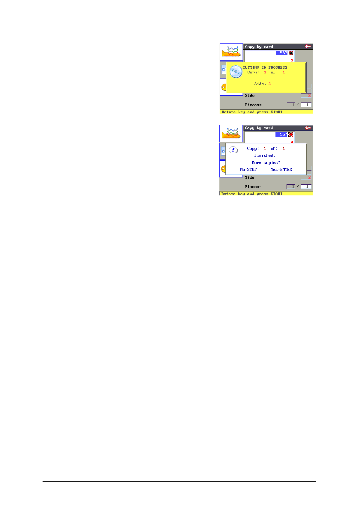
5) Position the second side of the key to be cut.
6) Press START, the display will show:
When the second side has been cut, the display will
show:
• Press STOP to finish the job.
• Press ENTER to continue cutting other keys with the same cuts as
the key just finished.
Copyright Silca 2016 35
Page 40
Unocode 399 PLUS Operating manual - English
F4
F3
F2
F1
F2
F1
F2
F1
Head
Tip
Reference
F2
F1
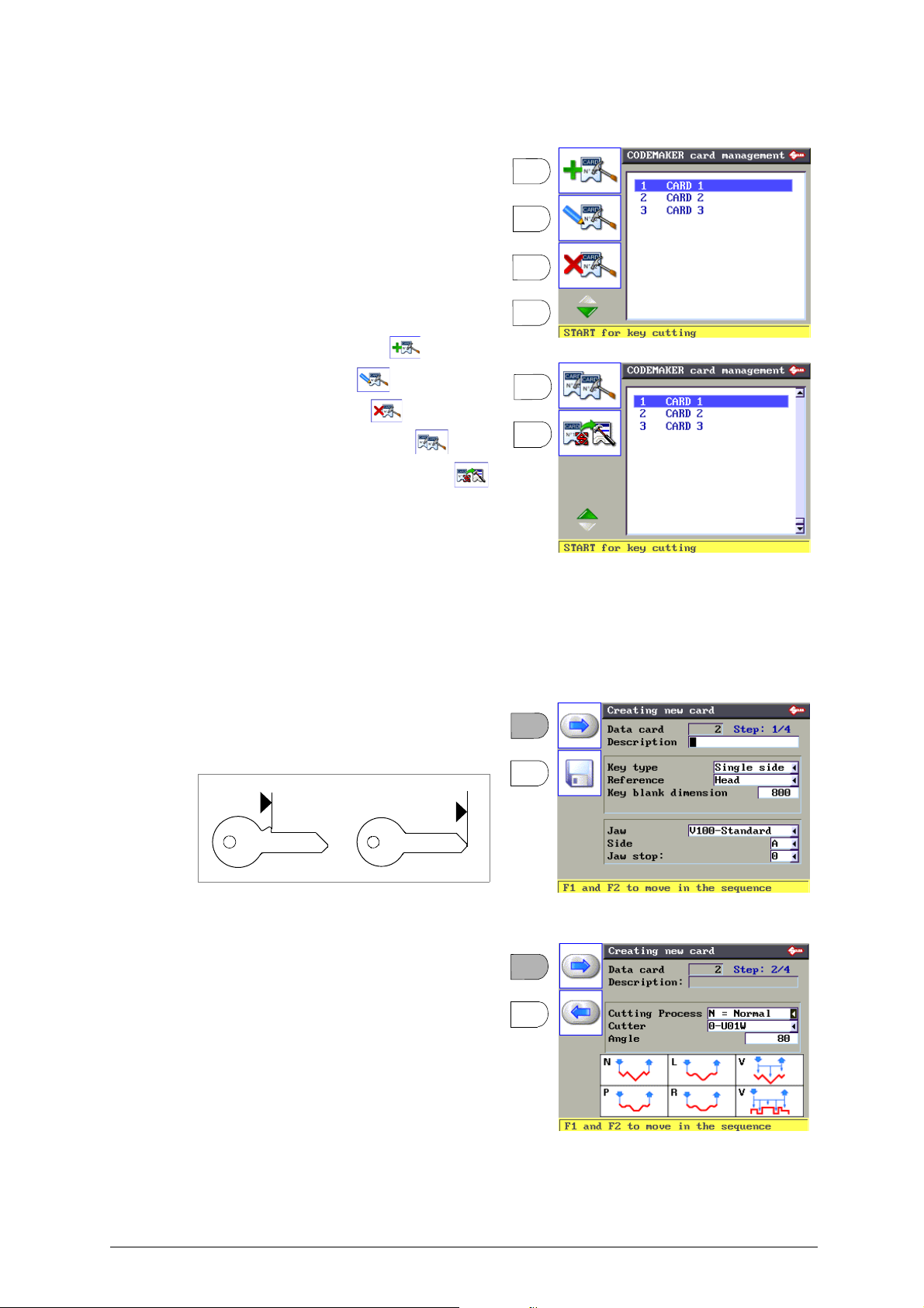
5.6 CODEMAKER CARD MANAGEMENT
The CODEMAKER function is used to create a
new data card with user definable cutting
parameters.
To enable the function press F4 from the initial screen.
A display will appear with the list of user created
data cards (if the machine is new the display is
blank).
The list of functions included with CODEMAKER
is represented by icons on the left.
• Create new data card (F1)
• Edit a data card (F2)
• Delete a data card (F3)
• Copy a data card (F4 then F1)
• Copy a SILCA data card (F4 then F2)
NOTE: creating of new cards is allowed for two key
types:
-SINGLE side
- DOUBLE SYMMETRICAL side
• Creating new data Card
Step 1
Assign a name (description) to the new data
card. All the data on the card, except the card
number, can be edited.
Once the values have been entered press F1 to
continue. The display will show:
Step 2
This display screen can be used to edit:
• Type of cut (see chap. 5.4)
• Cutter (set automatically in relation to the type of cut)
• Angle (can be set for types of cut different from “V”)
When editing is complete, press F1 to continue.
Press F2 to go back to the previous screen.
ATTENTION: if error messages appear, see chap.5.11.4
"CODEMAKER messages", page 60.
36 Copyright Silca 2016
Page 41
Operating manual - English Unocode 399 PLUS
F2
F1
number of
depths
symbols associated
with depths
depths entered
cutting angle
cutting spaces
flare (base of the cut)
cutting
depths
HEAD stop
TIP stop
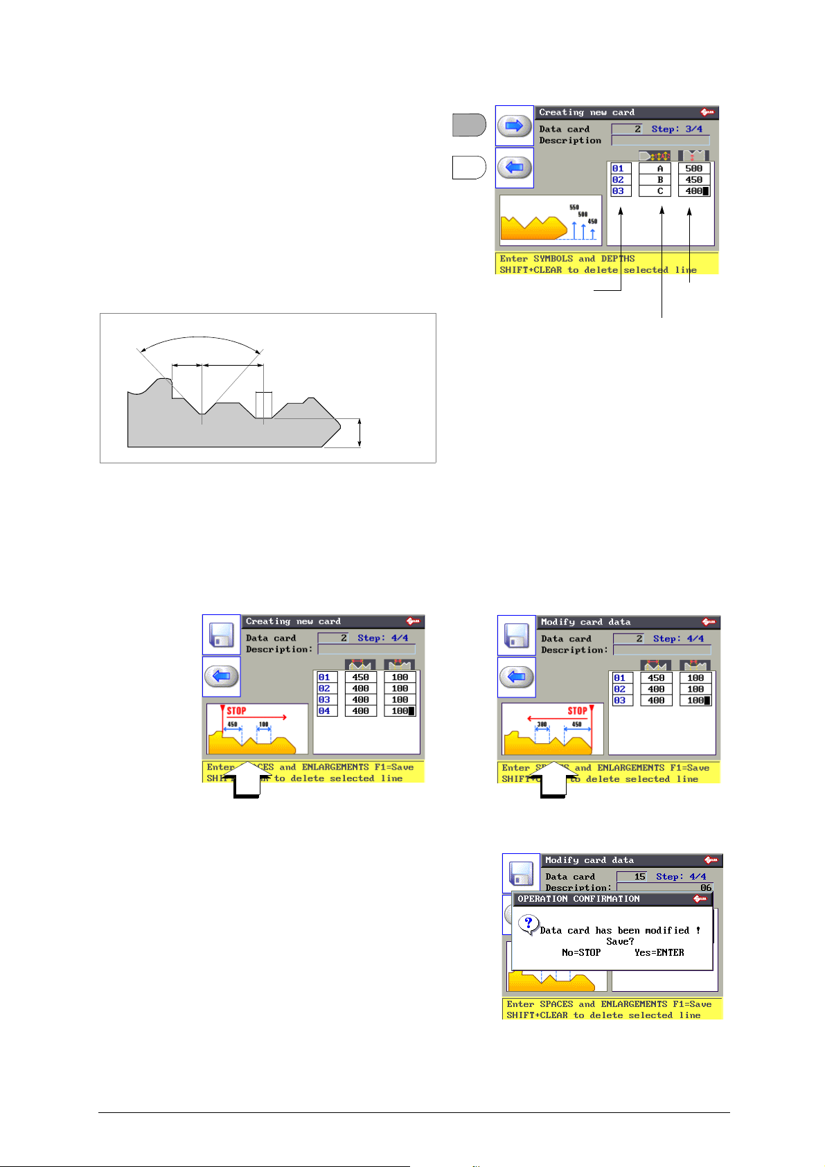
Step 3
• Insert the depth symbol (number or letter). Press
ENTER.
• Enter the depth measurement associated to the symbol.
Press ENTER.
Repeat the operation to the last depth.
All measurements are expressed in hundredths
of millimetres or inches, according to the setting
in machine Options (chap.5.9, page 52)
When the operation is finished, press F1 to
continue.
Fig. 30
Step 4
• Enter the figure for the cutting space from the key stop to the centre of the first cut and press ENTER.
• Enter the figure for flare related to the set cut and press ENTER.
• Enter the figure for the cutting space from the centre of the first cut to the centre of the second cut and press ENTER.
• Enter the figure for flare related to the set cut and press ENTER.
• Repeat the operation to the last cut.
When the operation is complete, press F1 to save and
continue. The display will show:
• Press ENTER to save the data.
• Press STOP to go back to the previous menu without saving the
data.
Copyright Silca 2016 37
Page 42
Unocode 399 PLUS Operating manual - English
F2
F3
F1
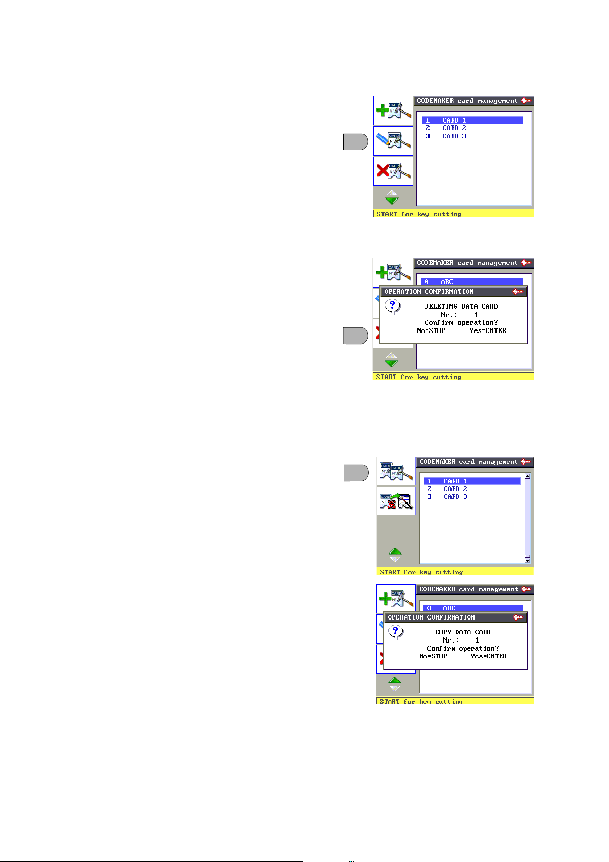
• Edit Data Card
This function is used to edit a card previously
created by CODEMAKER.
• Select the data card from the list and press F2.
• Follow the procedure described in “Create a new Data
Card” and edit the required parameters.
ATTENTION: if error messages appear, see chap.5.11.4
"CODEMAKER messages", page 60.
• Delete Data Card
This function is used to eliminate a data card
previously created by CODEMAKER.
• Select the data card and press F3.
ATTENTION: when a card is deleted the number of that
card cannot be reused.
• Copy Data Card
This function is used to copy a data card
previously created by CODEMAKER and edit its
parameters.
• Select the data card.
• Press F4 then F1.
•Press ENTER.
• Enter a description of the data card.
• Follow the procedure described in “Create a new data
card” and edit the required parameters.
38 Copyright Silca 2016
Page 43
Operating manual - English Unocode 399 PLUS
F4
F2
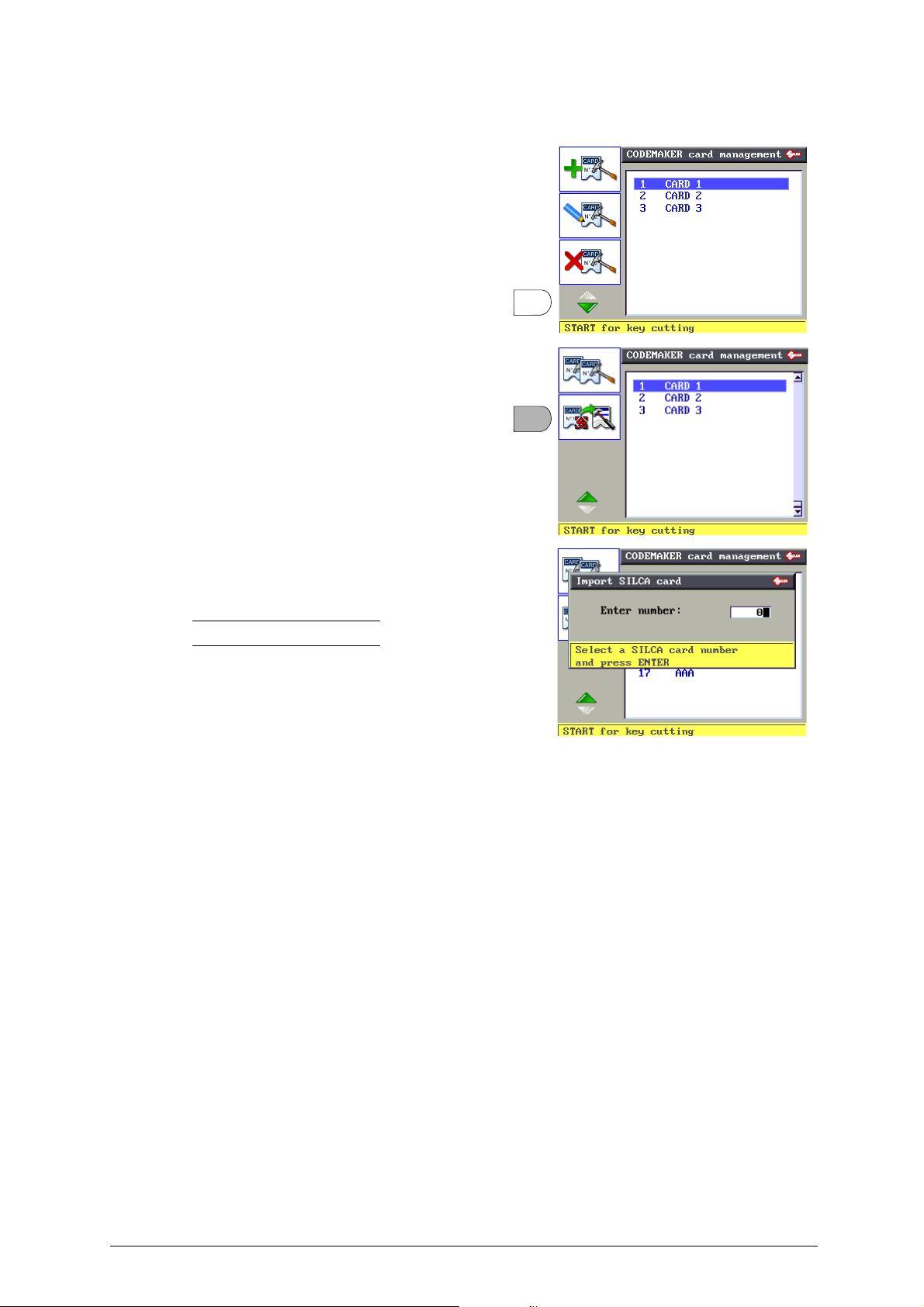
• Import SILCA Card
This function is used to copy an original SILCA
data card and edit its parameters.
• Press F4 then F2.
• Enter the number of the SILCA data card to be copied.
•Press ENTER.
• Follow the procedure described in “Create a new data
card” and edit the required parameters.
Note: not all SILCA data cards can be imported.
Copyright Silca 2016 39
Page 44
Unocode 399 PLUS Operating manual - English
F1
5.7 GAUGING
The following components on the machine have a specific ‘self-setting’ procedure wi th the use of
regulating templates (chap.1.5 "Accessories provided", page 9):
-CLAMPS
- CUTTERS
- ADAPTERS
CUTTERS do not need an automatic calibration system.
ADAPTERS provided as optionals do not require calibrating. However, if necessary adjustments can
be made to the cutting data, according to the procedures described in chap.5.3.2 "ACCESSORY
FUNCTIONS FOR “COPY BY DATA CARD”", page 25.
In the circumstances listed below (see events) it may be necessary to re-set one or all of the clamps
and/or cutters that the user has in possession. This operation is semi-automatic and requires close
attention to the instructions listed below.
EVENT
Replacement of photocells
Electronic board replacement
Replacement of sensors
Replacement of the cutter shaft
Replacement of the ball screws
Clamp V100 replacement
(with a new one of the same type)
Re-sharpening of existing cutter and/or cutter replacement
(with a new one of the same type)
Installation of optional clamps
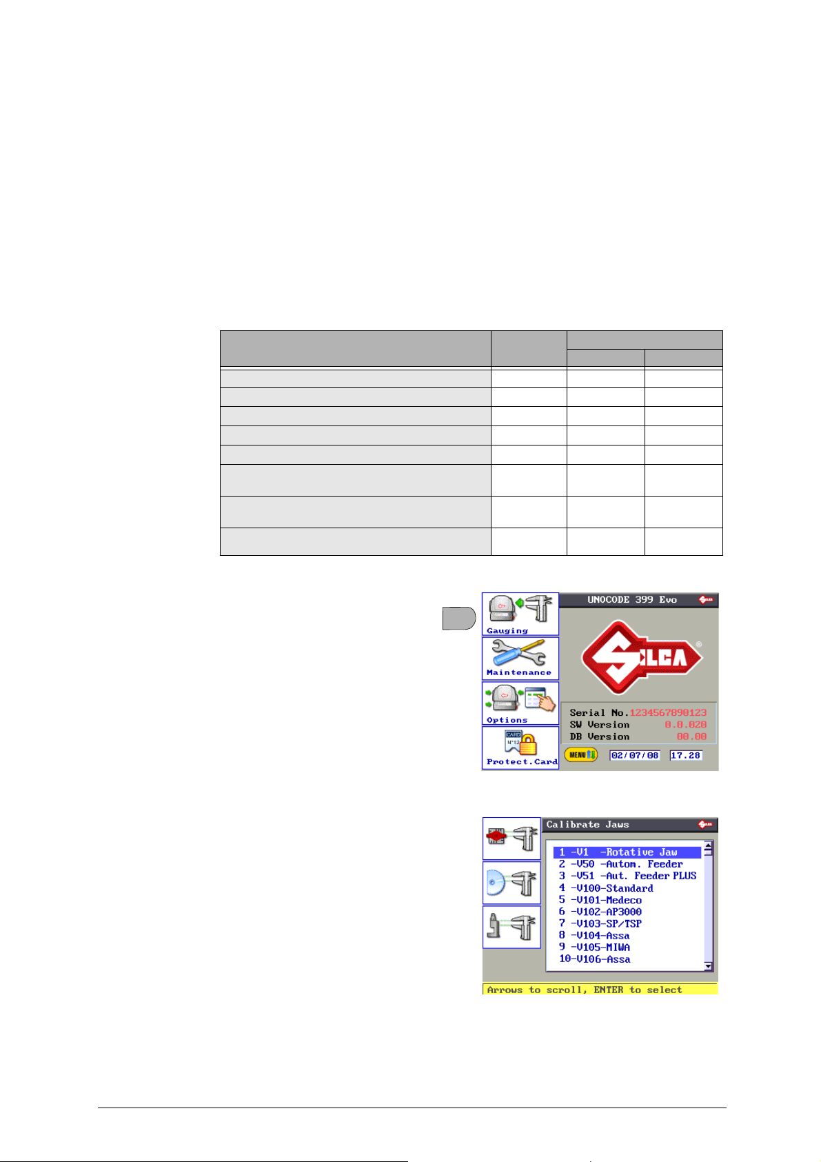
From the initial screen press MENU then F1 to
enable the function.
MACHINE
ZEROES
YES YES NO
YES YES NO
YES YES NO
YES YES NO
YES YES NO
NO NO NO
NO YES YES
NO YES
CALIBRATION
CLAMP CUTTERS
(if applicable)
NO
•Clamps
•Cutters
• Adapters
40 Copyright Silca 2016
Page 45
Operating manual - English Unocode 399 PLUS
F1
Z3
Z3
A
B
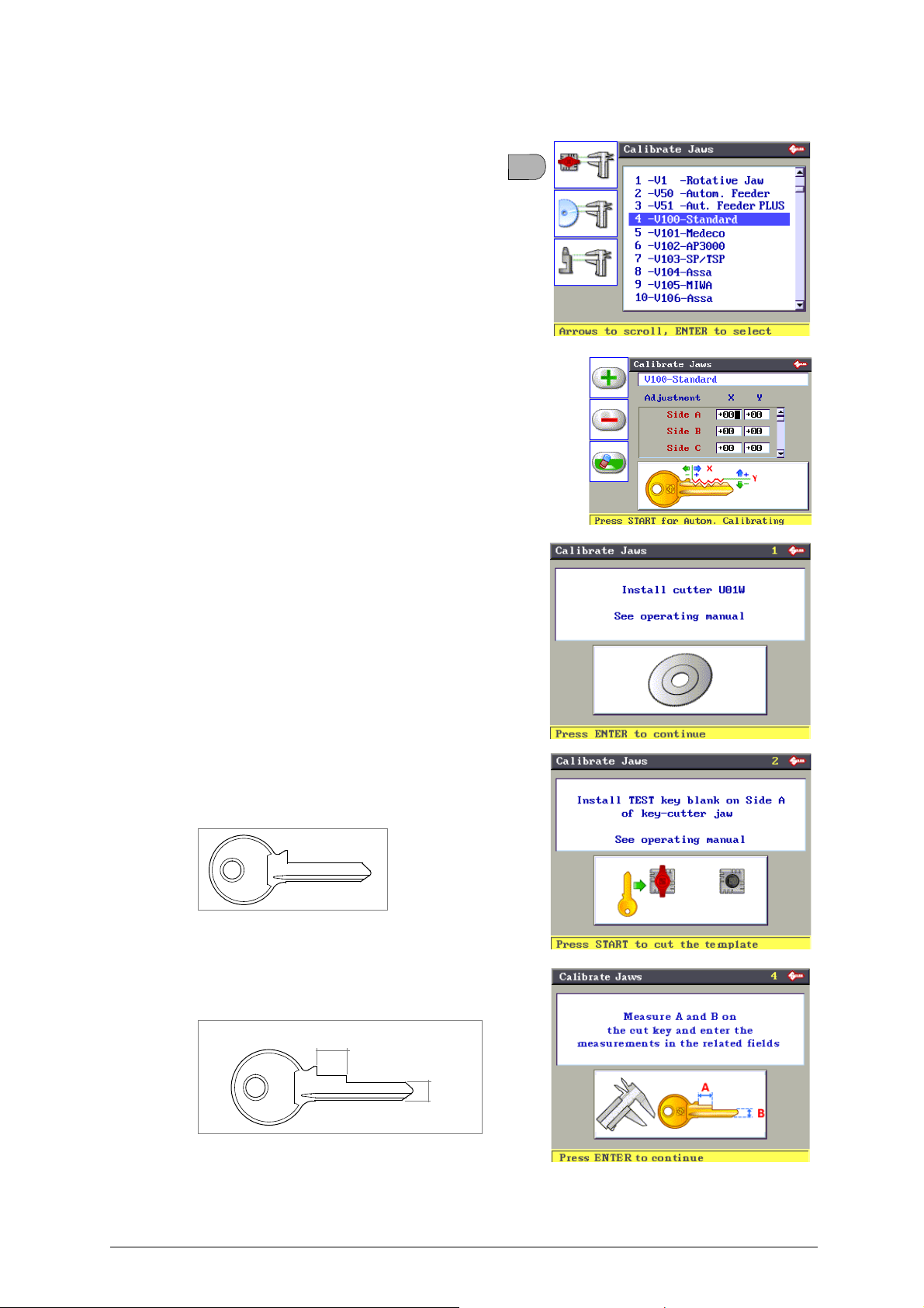
5.7.1 CALIBRATE STANDARD JAWS
1) Press F1 to access the list of clamps.
2) Select standard clamp V100, then press ENTER.
3) Press START to proceed with
will show:
4) Press ENTER, the display will show:
5) Make sure the U01W standard prismatic cutter is installed.
automatic calibration
; the display
ATTENTION:if the original Silca U01W cutter is
replaced with one that is NOT original or has been
sharpened, it will be necessary to repeat clamp
calibration and also gauge all the optional
cutters.
6) Press ENTER, the display will show:
7) Fit the test key blank (Z3 template) into side A of the clamp (Stop
0).
Fig. 31
8) Press START.
9) Clean the previously cut test key (template Z3) and measure
measurements A and B with a centesimal gauge.
Fig. 32
10) Press ENTER.
Copyright Silca 2016 41
Page 46
Unocode 399 PLUS Operating manual - English
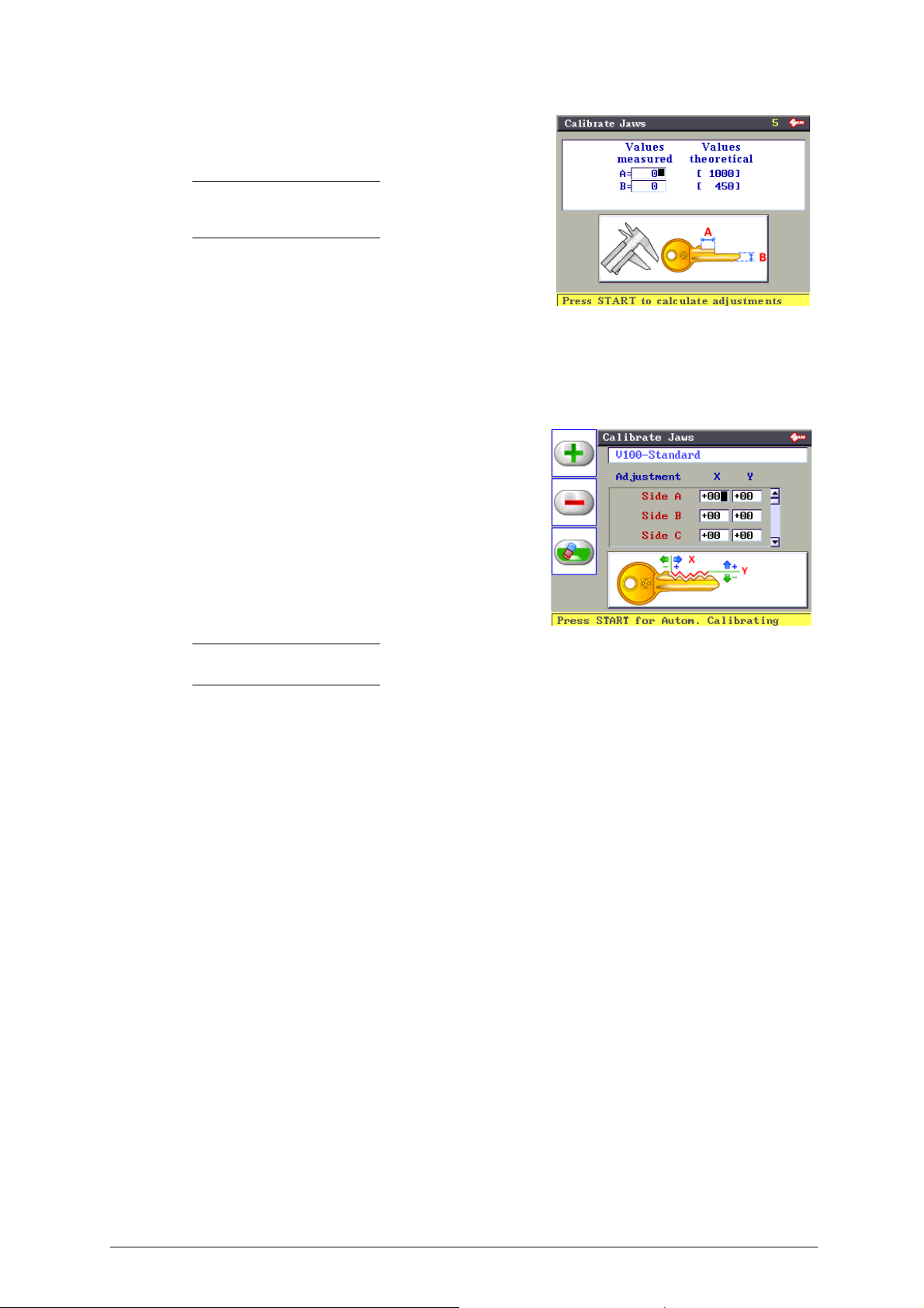
11) Enter the values for A and B, expressed in hundredths of a
millimetre, into the special fields.
Nota bene: values are accepted if they are the
same or differ by +/- 40 hundredths of a millimetre
from the theoretical value.
A: min. 960 max. 1040
B: min. 410 max. 490
12) Press ENTER to save the data. Press STOP to quit without
saving.
13) Press START. The operation is confirmed and the program goes
back to the Calibration menu for the V100 standard clamp.
Note: besides automatic gauging, the operator can make manual adjustments by entering the values in the X
and Y parameters.
ATTENTION:such adjustments (if necessary) are to be entered only after automatic
gauging, if applicable.
Adjustments can be made within a range of +30 and -30 hundredths of a mm.
Adjusting CLAMPS and ADAPTERS
Adjust depth Y (-30 to +30 hundredths of a mm):
- Y positive value: raise cut
- Y negative value: lower cut
Adjusting CUTTERS, CLAMPS and ADAPTERS
Adjust spaces X (-30 to +30 hundredths of a mm):
- X positive value: move cut to the right of the stop
- X negative value: move cut to the left of the stop
14) Press STOP to go back to the main menu.
42 Copyright Silca 2016
Page 47
Operating manual - English Unocode 399 PLUS
F2
F3
F2
F1
F3
F3
F2
F1
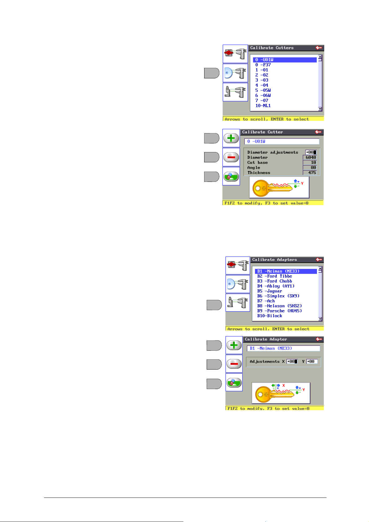
5.7.2 CALIBRATE CUTTERS
From the Gauging menu press F2 to enable the
cutter gauging function.
Select the U01W standard cutter and press
ENTER.
The display will show:
• Press F1 to get positive values (+).
• Press F2 to get negative values (-).
• Press F3 to cancel the set adjustments.
Adjust depth Y (-30 to +30 hundredths of a mm):
- Y positive value: raise the cut
- Y negative value: lower the cut
ATTENTION:if the original Silca U01W
cutter is replaced with one that is NOT
original or has been sharpened, it will be
necessary to repeat clamp calibration and
also gauge all the optional cutters.
5.7.3 CALIBRATE ADAPTERS
From the Gauging menu press F3 to enable the
Adapter gauging function.
Select the adapter to be calibrated and press
ENTER.
The display will show:
• Press F1 to get positive values (+).
• Press F2 to get negative values (-).
• Press F3 to cancel the set adjustments.
Adjust depth Y (-30 to +30 hundredths of a mm):
-
Y positive value
-
Y negative value:
Adjust spaces X (-30 to +30 hundredths of a mm):
-
X positive value
-
X negative value
: raise the cut
lower the cut
: move cut to the right of the stop
: move cut to the left of the stop
Copyright Silca 2016 43
Page 48
Unocode 399 PLUS Operating manual - English
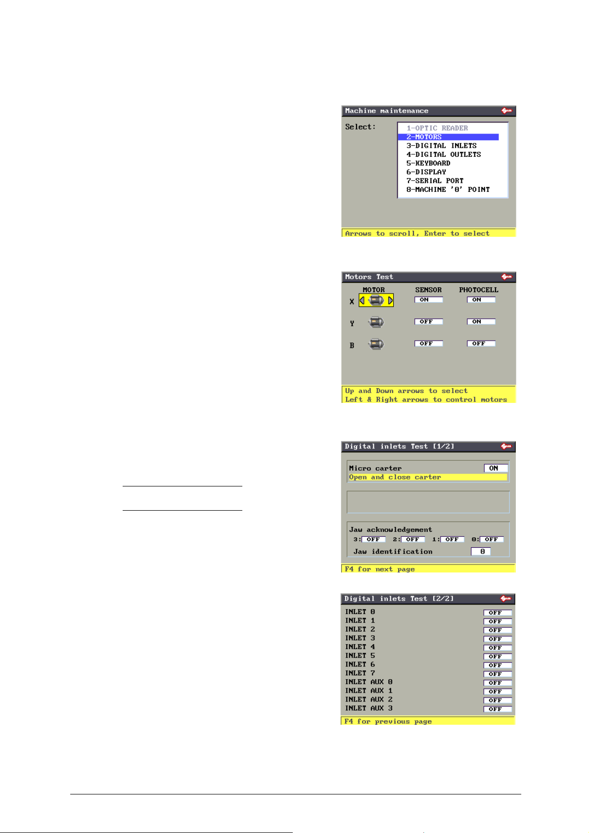
5.8 MAINTENANCE
From the initial screen press MENU then F2 to enable the function.
Use the up/down arrow keys to select the option and
press ENTER, or directly press the key relating to
the option number.
5.8.1 MOTOR TESTS
Read the instructions on the display carefully and
check that the carriage (or optional clamp in the
case of B) for the axis involved moves.
ATTENTION: during this test function all end of run controls
are disactivated; avoid moving the carriage up against its
mechanical stops.
5.8.2 DIGITAL INLETS TEST
- Lift and lower the protective shield checking that the machine’s display indicates OFF (with shield raised) to ON (with
shield lowered).
Note: if the ON/OFF transition is not made, contact Silca’s
Technical Assistance Dept.
Jaw acknowledgement: operational only with
electrically connected device.
This test can be carried out only when an automatic feeder (or
other optional component) is installed
on the machine
.
44 Copyright Silca 2016
Page 49
Operating manual - English Unocode 399 PLUS
Z4
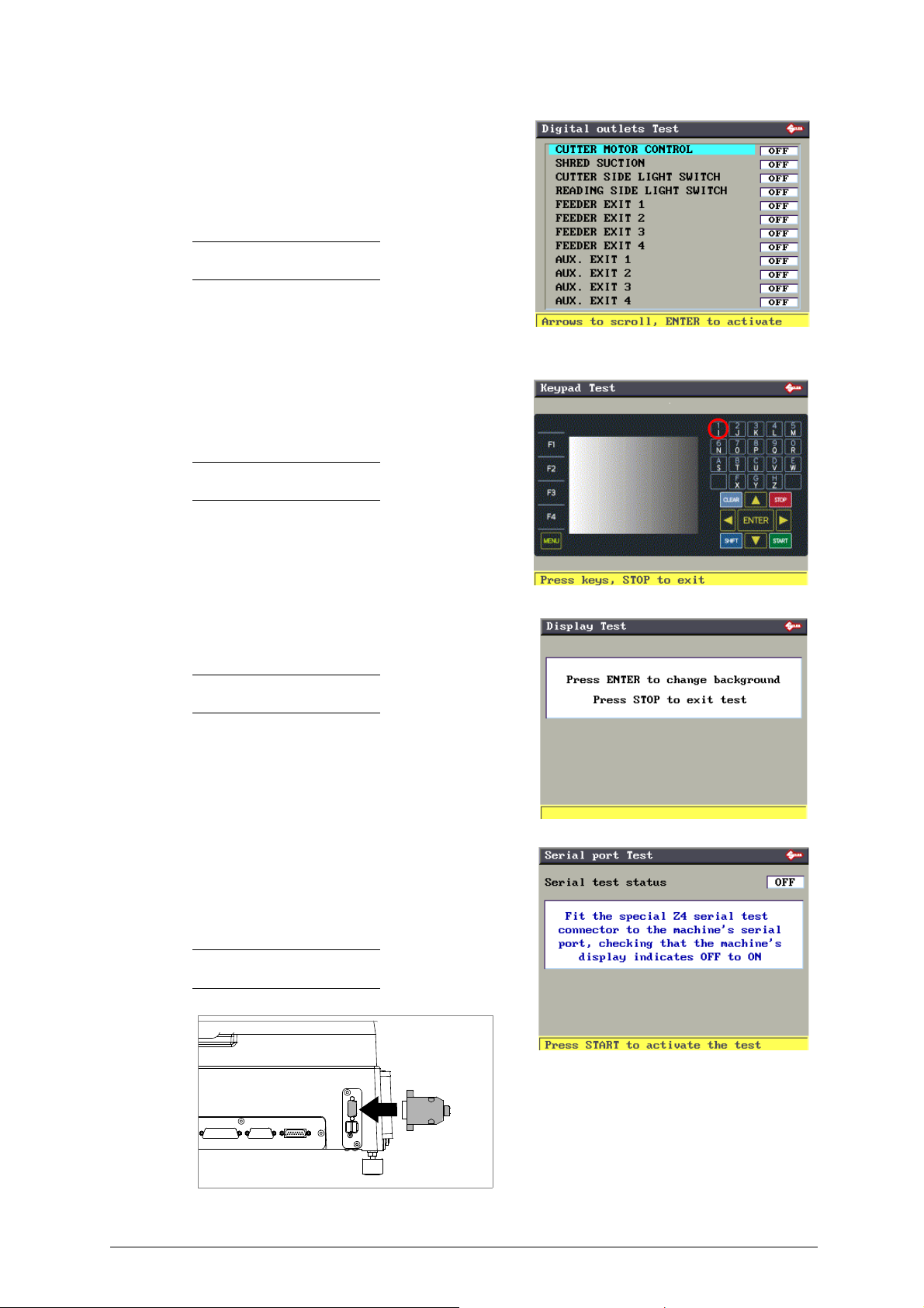
5.8.3 DIGITAL OUTLETS TESTS
Use the up/down arrow keys to move onto the
required field, lower the safety shield and press
START; it will go from OFF to ON.
- In the case of the cutter, the motor will also start.
- In the case of the cutting side or reading lamp, the one in question will illuminate momentarily.
Note: if this is not so, contact Silca’s Technical Assistance
Dept.
This test (Exit...) can be carried out only when an automatic
feeder (or other optional component) is installed
machine.
on the
5.8.4 KEYPAD TEST
Press all keys (except STOP) one at time and verify
that for every key pressed the display shows the
same key circled. Press STOP at the end of the
operation to quit the test.
Note: if this is not so, contact Silca’s Technical Assistance
Dept.
5.8.5 DISPLAY TEST
Press ENTER repeatedly to verify changes in the
background colour.
Note: if no changes are noticed, contact Silca’s technical
assistance department.
Press STOP to exit Test.
5.8.6 SERIAL PORT
Check that the machine’s display indicates OFF.
Fit the special (Z4) serial test connector (accessories
provided) to the machine’s serial port.
Press START and check that the machine’s display
indicates OFF to ON.
Note: if the ON/OFF transition is not made, contact Silca’s
Technical Assistance Dept.
Fig. 33
Copyright Silca 2016 45
Page 50
Unocode 399 PLUS Operating manual - English
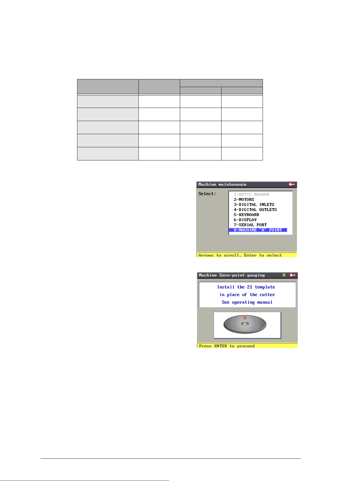
5.8.7 MACHINE ZERO POINTS
With the use of regulating templates (chap.1.5 "Accessories provided", page 9) the machine provides
a ‘self-setting’ procedure. These procedures must be carefully carried o ut following the descri ptions
and illustrations indicated below.
The table below indicates the situations where the Machine Zeroes function must be activa ted.
EVENT
Replacement of
photocells
Replacement of
the electronic board
Replacement of
sensors
Replacement of
the cutter shaft
Replacement of
the ball screws
MACHINE ZEROES CALIBRATING
CLAMPS CUTTERS
YES YES NO
YES YES NO
YES YES NO
YES YES NO
YES YES NO
Fit the template (Z1) in the place of the cutter; (to
remove the cutter read the instructions in
chap.7.3).
46 Copyright Silca 2016
Page 51
Operating manual - English Unocode 399 PLUS
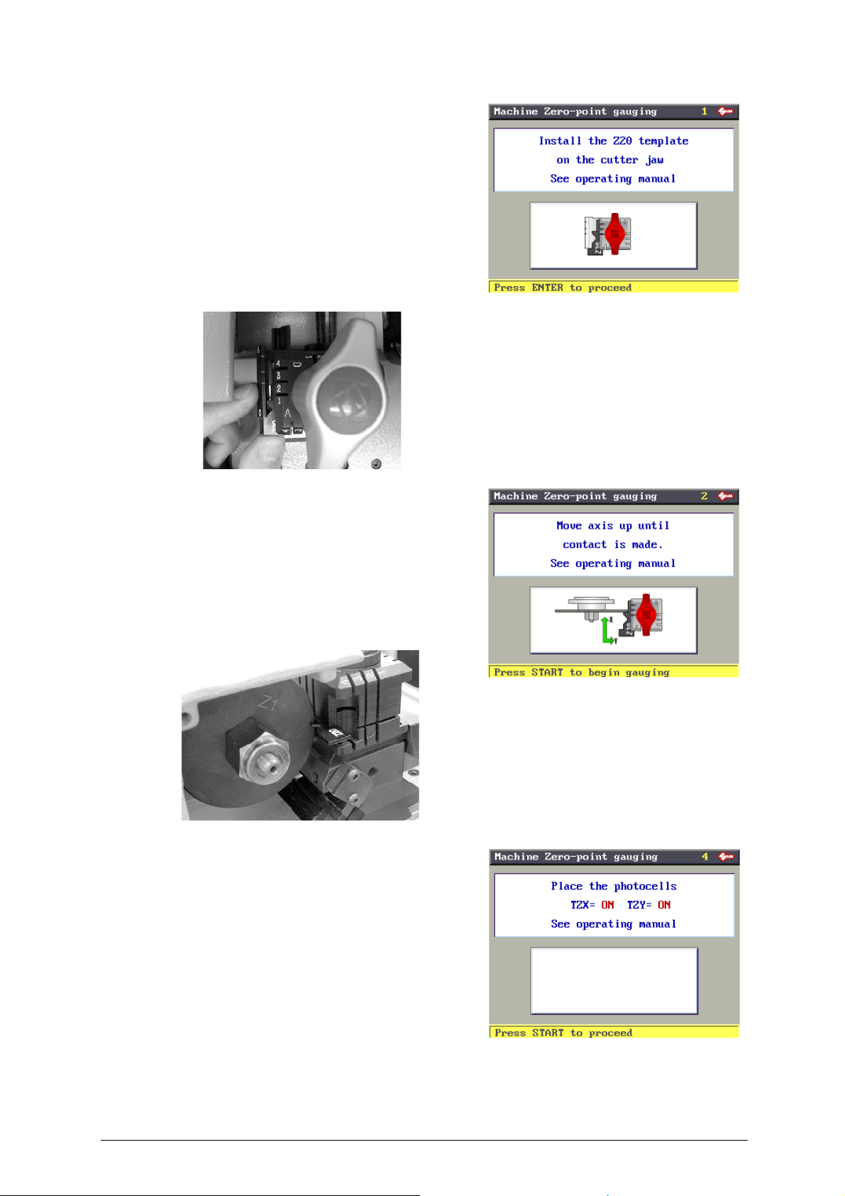
Press ENTER to continue, the display shows:
Read the instructions on the display and fit the Z20
template into the cutter side of the clamp, with Stop
0 as the reference.
Fig. 34
Fig. 35
Lower the gauge and press ENTER to continue.
The display shows:
Read the instructions on the display, move the
carriages manually so that the Z20 template is
taken into contact with the Z1 template (fig. 35) in
the vertical zone after the stop, up against the front
and up against the stem.
When the given position is reached, lower the
safety shield and press START.
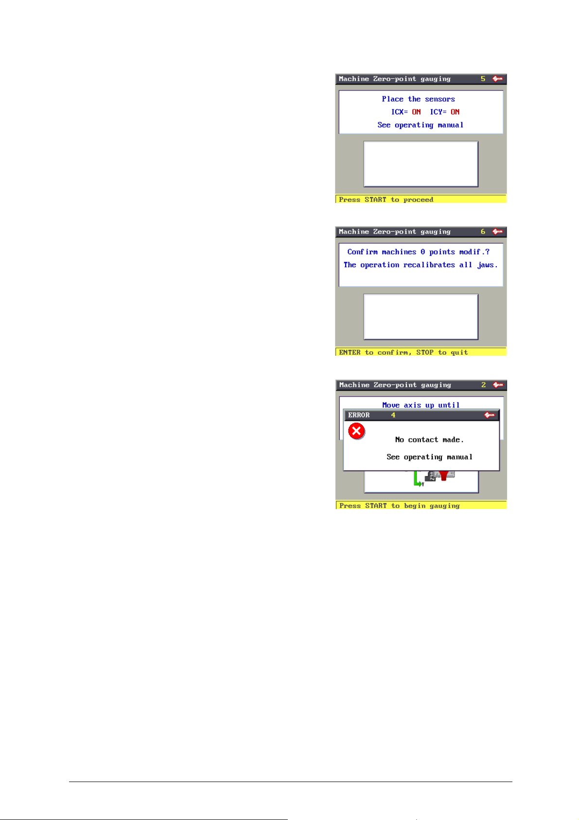
First the display will show: “Positioning” (**)
And then:
Copyright Silca 2016 47
Page 52
Unocode 399 PLUS Operating manual - English
Press START, the display will show:
Press ENTER to confirm, only if the previous
parameters were ON (***).
Press STOP to cancel the operation and not
confirm the adjustments made (if there is one value
or more on OFF). The previous values remain valid
(already in the machine’s memory).
ATTENTION: if the STOP key is pressed, the new settings
will be lost. If so, only the previous setting values will remain
valid.
(**) If the templates have not been properly
positioned the following ERROR message appears:
(***) If one or both the photocells or one or both the sensors are OFF, repeat the operation following
the procedure described in chap. 5.8.8, page 49.
48 Copyright Silca 2016
Page 53
Operating manual - English Unocode 399 PLUS
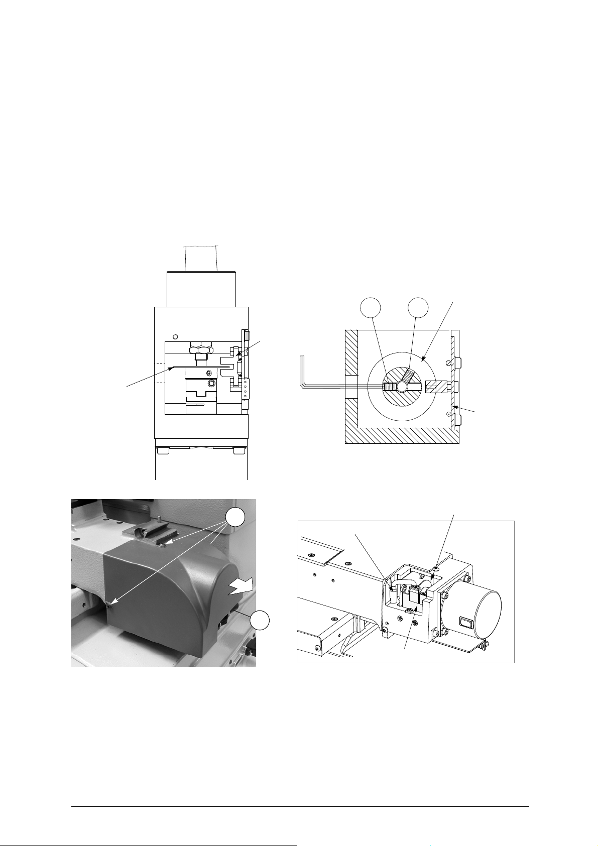
G1 G2
X axis
X axis
photocell disk
photocell
X axis
photocell disk
X axis
photocell
card
Y axis photocell
Y axis sensor
Y axis photocell disk
B5
J1
5.8.8 PHOTOCELLS AND SENSORS REGULATION
PRELIMINARY OPERATIONS
1)
turn the machine off and unplug it from its power supply cable
2) remove the back panel
(chap.7.8).
3) loosen the (G1) and (G2) grub screws that secure the X axis photocell disk (fig. 36).
4) remove the bottom panel (chap.).
5) disconnect the (J1) Y axis cable from the carriage (fig. 37).
7) unscrew the 3 (B5) fixing screws and remove the Y axis protective cover by pulling it in the direction shown in fig. 38.
8) plug the Y axis (J1) cable.
9) turn the machine on and carry on with the procedures described on
.
page 50 .
Fig. 36
Fig. 37
- the machine will take the X and Y axes to a predefined position.
- the operator must manually rotate the X and Y photocell disks up until the cut in the disks face the photocells card.
Copyright Silca 2016 49
Page 54
Unocode 399 PLUS Operating manual - English
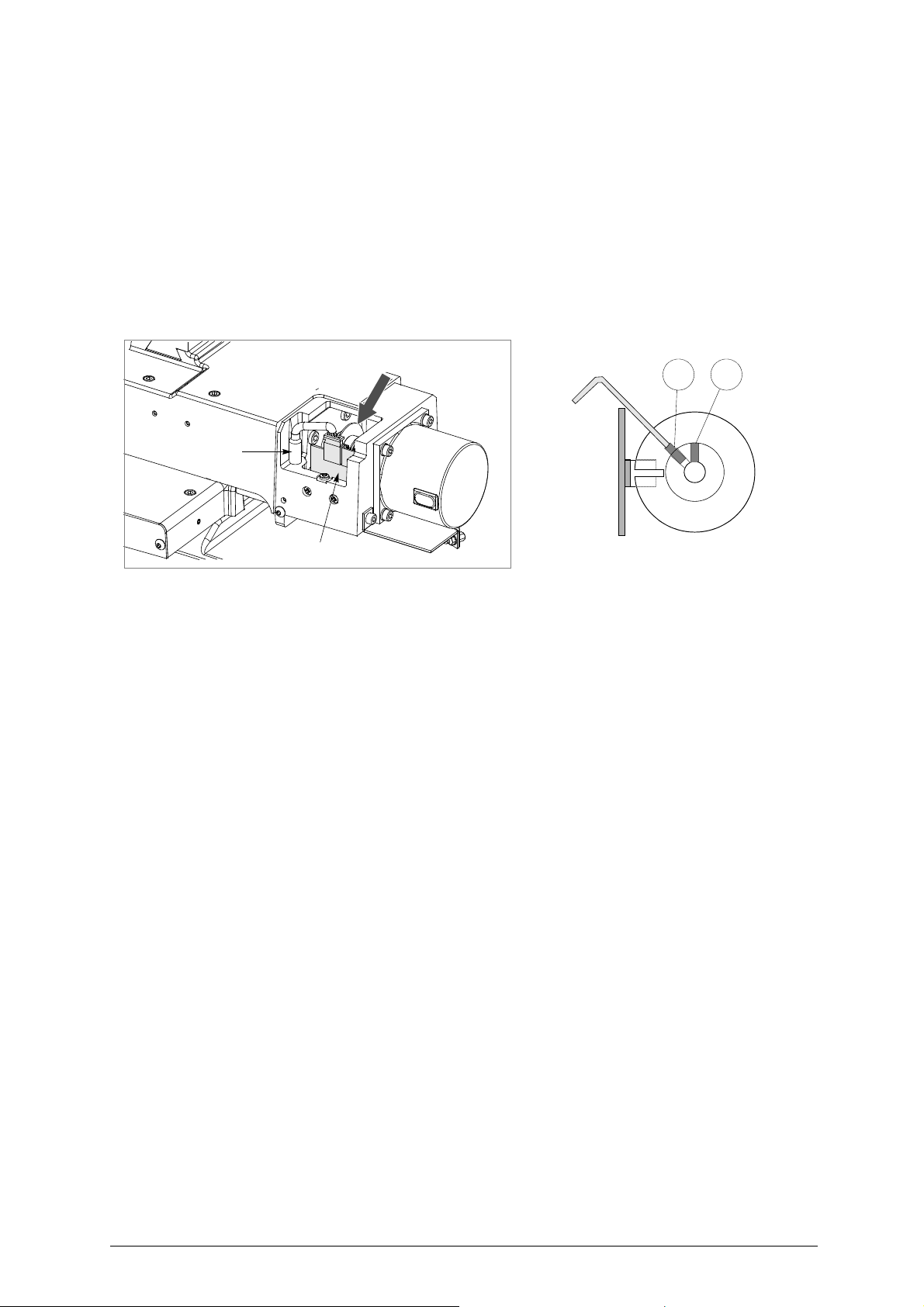
G3 G4
Y axis photocell
Y axis sensor
Y axis photocell
• manually turn the Y axis disk
:
(fig. 38) up
until the display’s description changes from OFF to ON
• use the provided allen key to tighten the (G3) grub screw.
X axis photocell
• manually turn the
:
X
axis disk
(fig. 36) up
until the display’s description changes from OFF to
• use the provided allen key to tighten the (G1) grub screw (fig. 36).
9) lower the protective shield
10) press
START.
.
- the machine goes on to a new position and is ready for regulating the sensors.
.
ON.
Fig. 38
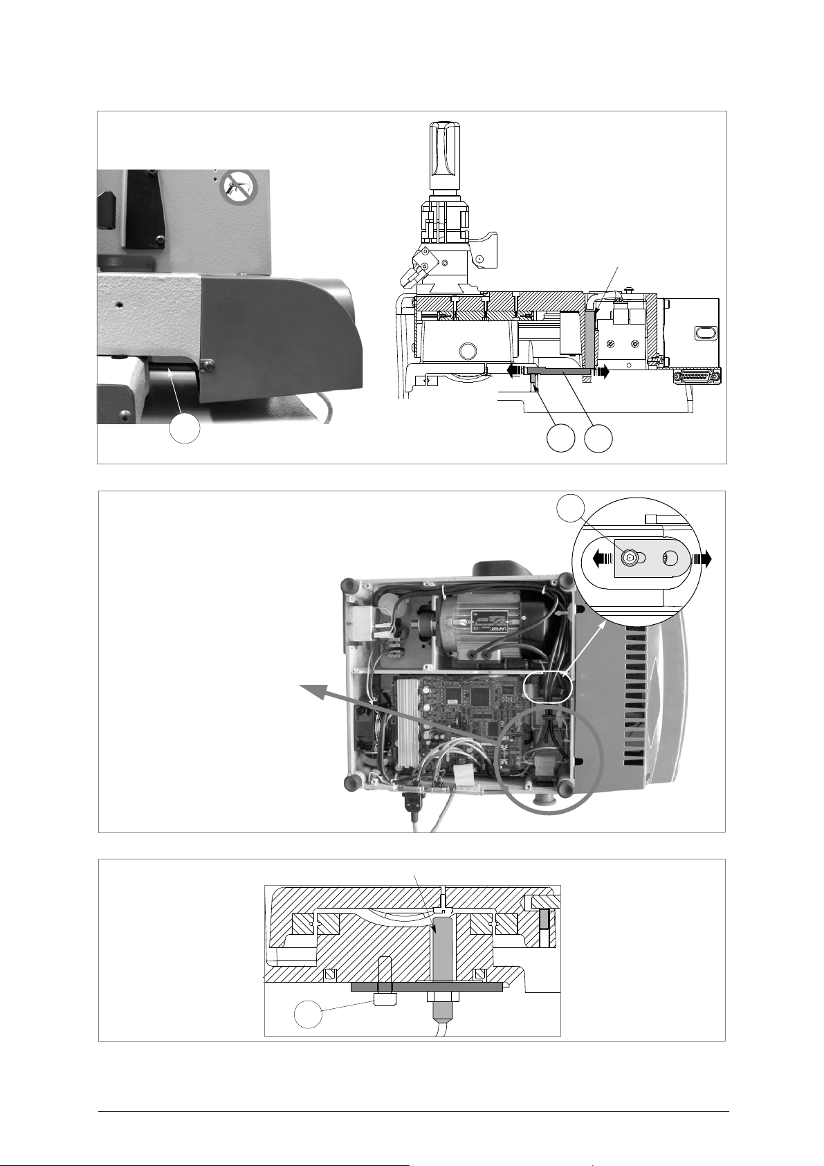
Regulating the Y axis sensor
:
• raise the protective shield.
• use the provided allen key to loosen the (C1) grub screw; manually rotate the (C2) rod in both directions up until the
changeover point from OFF to ON is found.
• tighten the (C1) grub screw to secure the rod.
Regulating the X axis sensor
:
• carefully tip the machine over.
• remove the bottom panel by unscrewing all 8 securing screws.
• loosen the (C3) screw that secures the sensor support plate. Manually move the sensor support plate up until the display’s
description goes from OFF to ON.
• tighten the (C3) screw to secure the plate back into place.
• re-position the machine back on its workbench and lower the protective shield.
•press START.
50 Copyright Silca 2016
Page 55
Operating manual - English Unocode 399 PLUS
C2
C1
Y axis sensor
C2
bottomview
ATTENTION: if it is necessary to
work close to this area with the
machine turned on (e.g. to regulate
the X axis sensor) take great care not
to touch any components on the
machine’s electronic boards as it is
connected to 230 Volts.
C3
X axis sensor
C3
Figura 39
Figura 40
Fig. 41
Copyright Silca 2016 51
Page 56
Unocode 399 PLUS Operating manual - English
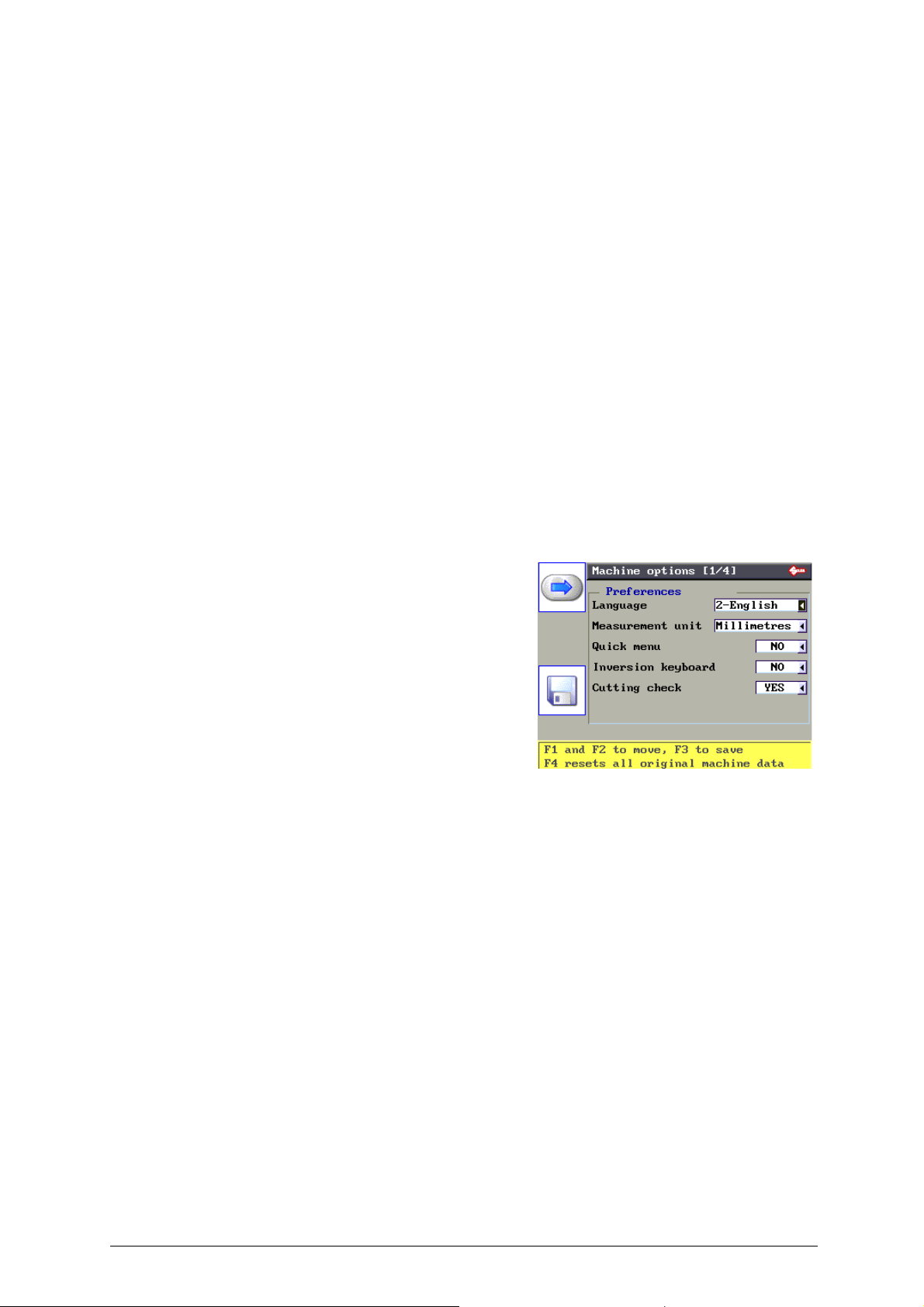
5.9 OPTIONS
From the initial screen, press MENU then F3 to enable the function.
There are 4 machine option windows that are selected by pressing F4.
ATTENTION: Hold down F4 to take the machine back to its initial state (with the original parameters set by Silca).
Machine Parameters/Options that can be forced from the original factory setting:
Rapid speed: 4000
Cutting speed: 400
Reading speed: 350
Minimum distance from stop: 50
Stop adjustment enabling: 0 --> Disabled
Parameter X stop adjustment: 0
Parameter Y stop adjustment: 300
Parameter H stop adjustment: 370
Parameter L stop adjustment: 0
Measuring unit: 0
Date format: 0 --> GG/MM/AA
Time format: 0 --> 0-24
Keyboard Inversion: 0 --> Disabled
Cutting check: 1 --> Enabled
Rapid menu for PC queue: 0 --> Disabled
Machine Options [page 1/4]
The display shows: Preferences
Current language:
use the arrow keys (rh/lh) to select the measuring unit
required (mm = millimetres, inches) then press ENTER to
confirm.
Measuring unit:
use the arrow keys (rh/lh) to select the measuring unit
required (mm = millimetres, inches) then press ENTER to
confirm.
Key pad inversion:
this function is normally disabled. Use the arrow keys (rh/
lh) to select enabled or disabled then press ENTER to
confirm.
The operation is used to invert the function of the
alphanumerical keys.
With “Key pad inversion” disabled:
• To digit number 3 press 3/K
• To digit the letter K: press SHIFT + 3/K
With “Key pad inversion” enabled:
• To digit number 3: press SHIFT + 3/K
• To digit the letter K: press 3/K
Cutting check:
This option is used to enable and disable control of the combinations entered on the cutting card, by pressing
SHIFT + [up arrow].
Default is enabled, i.e. there is constant control that the combination entered is compatible with the cutting
path.
Such control has certain rules that prevent the operator from creating keys which are not guaranteed to work.
52 Copyright Silca 2016
Page 57
Operating manual - English Unocode 399 PLUS
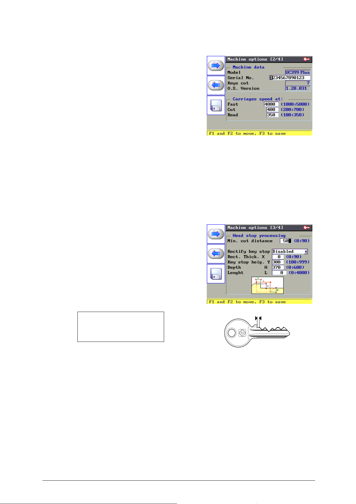
Machine options [page 2/4]
the display shows: Machine data
Model:
machine model.
Serial No:
the serial number corresponding to that on the ID plate
located on the back of the machine.
Keys cut:
cutting completed.
Operating System Version:
version of the machine operating system.
Carriage speed
Fast speed:
the speed at which the carriages approach the cutting
zone before cutting is started. The set speed is that for
ideal conditions, but the operator can change it from a
minimum of 1000 to a maximum of 5000.
Cutting speed:
corresponds to the speed at which the carriage advances during key-cutting. The set speed (400) is that for
ideal conditions, but the operator can change it from a minimum of 200 to a maximum of 700.
Reading speed:
Recommended reading speed is 350; the operator can change from a minimum of 100 to a maximum of 350.
Machine options [page 3/4]
The display shows: Head stop processing
Min. cut distance:
The number shown on the machine’s display
represents the X axis distance between the key
blank shoulder and the beginning of the first cut (fig.
42).
This function is extremely important with keys that
require cuts on both sides as it ensures precise
positioning on the key 2nd side.
The set figure is 50 hundredths of a mm, which can be varied
between min.0 - max. 90 hundredths of a mm.
ATTENTION: settings that are too high may render precise
cuts impossible, with the following message on the display:
MIN. Parameter of
DISTANCE FROM STOP
is incompatible with
selected card!
Fig. 42
Rectify Key Stop:
The machine does not normally allow for key stop rectification.
However, it is possible, when necessary, to rectify the stop by removing a part of it, and arrange cutting
according to the new key stop created.
If the operation is enabled, 4 items are required:
Rectification thickness X:
thickness of the part to be removed, quantified in hundredths of a mm (min. 0 - max.90)
Key stop height Y:
height of the stop read by a gauge on the key, quantified in hundredths of a mm. E.g.: Y = 3 mm = 300
hundredths of a mm (min.100 - max.999).
Depth H:
depth of the part to be removed, quantified in hundredths of a mm, relating to the key blank measurements
(min.0 - max.600).
Length L:
distance in hundredths of a mm of the axis from the cutter, relating to X (min.0 - max.4000).
Copyright Silca 2016 53
Page 58

Unocode 399 PLUS Operating manual - English
Machine options [page 4/4]
The display shows: Clock management
Date and time format:
use the arrow keys (rh/lh) to select the DATE format (DD/
MM/YY by default, or MM/DD/YY or YY/MM/DD) and
TIME format (0 - 24 by default or am - pm) required, then
press ENTER to confirm.
Setup date and time:
use the up/down arrow keys to enter the field to be edited
and use the arrow keys (rh/lh) to go to the item to be
edited. Edit with the numerical keys and press ENTER to
confirm each item. Press F4 for overall validation of the
edited string. The same preset data will also be shown
along the bottom.
Battery status: CHARGED
Automatically reads whether the battery is charged or
flat. The battery is used exclusively for the date function.
54 Copyright Silca 2016
Page 59
Operating manual - English Unocode 399 PLUS
5.10 ENABLING
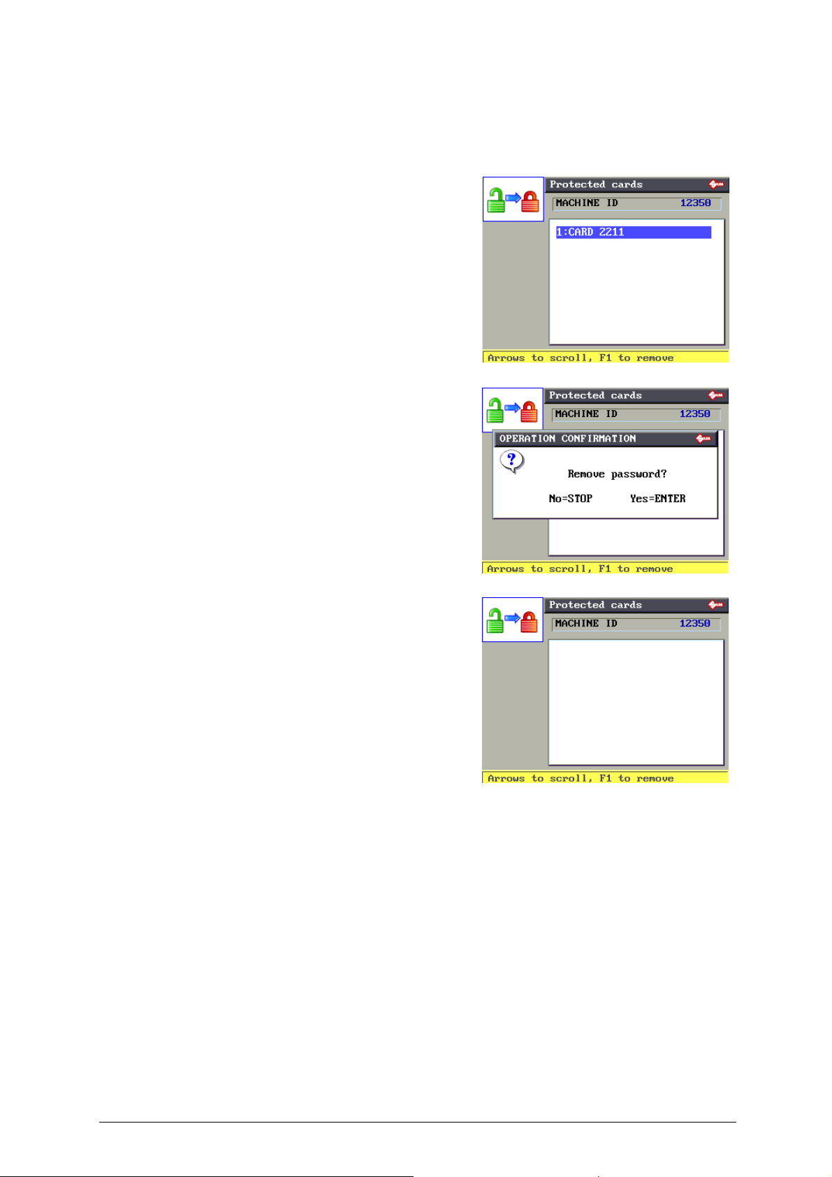
From the screen, press MENU and/or F4 to enable the function.
This display shows all the protected systems enabled and allows them to be protected again, if
necessary.
E.g.:
In this case a single protected card has been
previously enabled.
As explained on the display, use the arrow keys (up
and down) to select the enabled protected system.
Press F1 to make it protected again.
The display shows a further message requiring
confirmation of removal. Press STOP to quit the
operation without making alterations, press F1 to
protect the selected card.
Press ENTER, the display will show:
Copyright Silca 2016 55
Page 60

Unocode 399 PLUS Operating manual - English
5.11 MESSAGES
5.11.1 ATTENTION MESSAGES
Data card
not available!
• The entered data card number is not available in the machine’s data base.
Non-feasible
combination!
• The entered cuts cannot be carried out (see chap.5.4, page 31).
ATTENTION!!
Install cutter:
U01W
This message appears when the cutter must be changed with one that is compatible to the type of cuts required for the
•
entered data card number
.
Clamp not
available!
This clamp is not available in the machine’s data base
•
.
Cutter not
available!
This cutter is not available in the machine’s data base
•
.
Adaptor not
available!
• This adapter is not
available in the machine’s data base
.
Type of cut
not available!
• The entered data card number requires a type of cut that is not available in the machine’s data base.
MIN. Parameter of
DISTANCE FROM STOP
is incompatible with
selected card!
• The minimum distance from the key stop position overlaps the first cut on the key (chap.5.9, page 52).
56 Copyright Silca 2016
Page 61

Operating manual - English Unocode 399 PLUS
ATTENTION
Depth limit
exceeded!
• During the cutting cycle one or more depth exceeded the maximum limit. These depths are automatically aligned to the
maximum permitted depth.
Non-feasible
function !
• Indicates that the entered function is not yet available.
Jaw
not calibrated !
• This message appears when the calibration data are not on the machine.
Data format
not compatible!
See operating manual
• This message appears when the data are not compatible with the data structure.
Zero point axis
Movement
not completed!
• This message appears when axis clearance has not been successful.
Modifications are only
applied to COPY BY CARD
and COPY WITH
ADJUSTMENTS
• Indicates that the adjustments inserted can only be applied to the two cases and not to Copy from original.
Resetting of original machine data Con-
firm operation?
No=STOP Yes=ENTER
• This message appears if you wish to reset the machine on the initial settings, i.e. with the default parameters set up by Silca
(see chap.5.9, page 52).
Copyright Silca 2016 57
Page 62

Unocode 399 PLUS Operating manual - English
5.11.2 ERROR MESSAGES
ERROR 3
Exceeded setting
tolerance limit
See operating manual
• The automatic setting revealed a variation that exceeded the permitted nominal figure setting reference. Carefully repeat
the setting procedure.
ERROR 4
No template
contact made.
See operating manual
• During the setting of the “machine’s zero points” there is a contact failure between the two templates (see chap.5.8.7, page
46).
ERROR 5
Key cannot be
copied
• This message indicates that during the reading cycle an anomalous form has been revealed that cannot be reproduced
with the cutters provided.
ERROR 6
Machine ID
not defined
See operating manual
• The Machine ID has not been set. In such cases access cannot be gained to Protected Systems until the Machine ID is
set. Select menu 5.10 "ENABLING"and check that the Machine ID is different from 0. To set Machine ID ask for a Software
update valid for your machine and install with the SILCA WinTransfer Program or SILCA Code Program.
58 Copyright Silca 2016
Page 63

Operating manual - English Unocode 399 PLUS
5.11.3 ALARM MESSAGES
ALARM 2
TEMPERATURE ALARM
Turn the machine off!
• The electronic control board has exceeded the maximum permitted temperature. Check the cooling fan (SEE chap.7.1
"Trouble shooting", page 63).
ALARM 3
I/O POWER ALARM
Check fuse F4!
• Indicates that the fuse has blown due to a short circuit in an inlet or outlet (see chap.7.1 "Trouble shooting", page 63).
ALARM 4
DIGITAL OUTLET
PROTECTION ALARM
Turn the machine off!
• Indicates a short circuit in port P (IN/OUT) (see chap.7.1 "Trouble shooting", page 63).
ALARM 5
CUTTER MOTOR
ALARM
Check fuse F1!
• Indicates that the fuse has probably blown (see chap.7.1 "Trouble shooting", page 63).
ALARM 6
CUTTER MOTOR
Fault on motor circuit!
• Indicates a fault on the electronic control board.
Faulty contact made!
Press START to move
axis at zero point.
• This message appears when the machine detects an unexpected contact.
Before calibrating the jaw:
V...
it's necessary to have
calibrated the V100 jaw
• This message appears when gauging a clamp that requires the previous gauging of the standard V100 clamp.
Copyright Silca 2016 59
Page 64

Unocode 399 PLUS Operating manual - English
5.11.4 CODEMAKER MESSAGES
Key Blank dimension
out of range!
Limit values:
• Appears when the depth value exceeds the key blank measurement assigned to the key.
Cutting angle out of range!
Limit values:
• Appears when the set angle is higher or lower than the limit allowed by the cutter in use.
Cutting Depth out of range!
Limit values:
• Appears when the set depth is higher or lower than the limit for the clamp in use.
Spacing value out of range!
• Appears when the value of a set space is not within the limit.
Base of cut out of range!
Limit values:
• Appears when the value of a set flare is not within the limits.
Cutting process exceeds
X axis carriage range !
See operating manual.
• The set combination of spaces and flares exceeds the maximum run allowed for the space axis.
Overlapping base of cut!
• Appears when the value of a set flare would overlay a previous flare.
Spacing values
are not compatible
with base of cuts!
• Appears when the value of a space is altered in such a way as to cause the flare to overlay the previous one.
The cut depth is not
compatible with cutting
edge of the cutter.
See operating manual.
60 Copyright Silca 2016
Page 65

Operating manual - English Unocode 399 PLUS
• Appears when the cutting depth would not allow the cutter to move sideways.
The cut depth exceeds
the safety limit of
the selected jaw side!
See operating manual.
• The depth exceeds the limits established for the clamp side in use.
The cutting process
is incompatible with
the STOP position !
See operating manual.
• Cutting cannot be done for the type of stop set.
The depth values
can't be greater than
the Key Blank Dimension
See operating manual.
• Appears when the key blank measurement is altered and the depths exceed such measurement.
Copyright Silca 2016 61
Page 66

Unocode 399 PLUS Operating manual - English
6 CLEANING
• keep the operational parts of the machine as clean as possible by brushing away the chippings in areas where they
accumulate during cutting operations.
• under no circumstances must compressed air be used to clear the work zone of chippings as this will blow them
onto the moving parts.
• Never use oil-based products or solvents to clean painted surfaces, jaws, electric or electronic
connections, display and/or safety screens.
• Do not use alcohol to clean plexiglass carters and display.
62 Copyright Silca 2016
Page 67
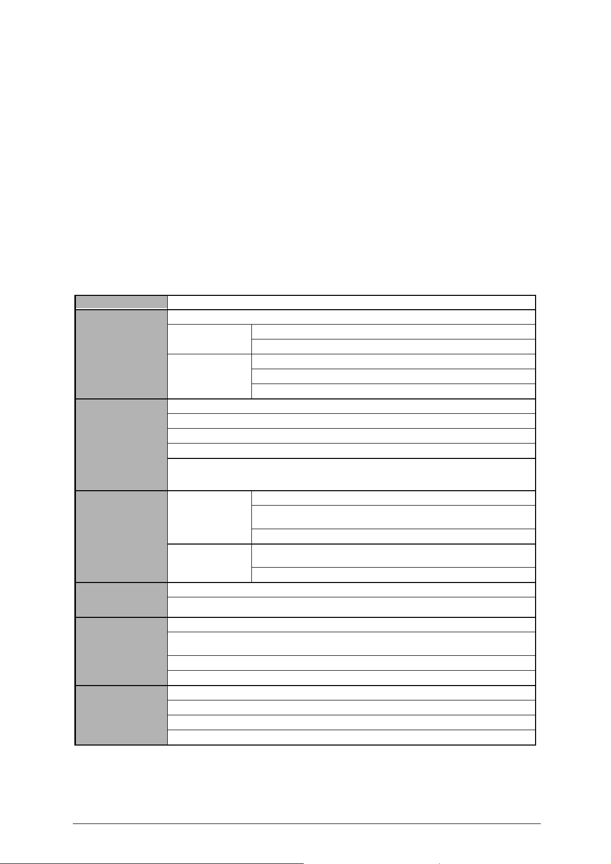
Operating manual - English Unocode 399 PLUS
7 MAINTENANCE
ATTENTION: for repairs or replacement of parts for maintenance, the ‘CE’ mark is guaranteed only if original spare parts
provided by the manufacturer are used.
Although the
if necessary, replace the parts subject to wear and electric/electronic parts (fuses, circuit boards, etc.) in the event of faulty
operation
ATTENTION: for normal servicing of the burnished mechanical parts, we recommend using lubricants or protective oil, e.g.
WD40 or similar. Do not contaminate the electronic parts with the oil.
Replacement is simple and can be carried out by the operator consulting the instructions.
Before starting any type of maintenance (controls or replacements), read the instructions below
• never carry out maintenance with the machine switched on
• always remove the main power supply cable
• strictly follow all the instructions in the manual
• use original spare parts (see Spare Parts sheet provided).
7.1 TROUBLE SHOOTING
FAULT PROBABLE CAUSE
Machine is on, with no
message on its display:
cutter motor not working:
X, Y and B axes motors are
not working
Protective shield is closed but
the display reads “‘close
shield”
Keyboard not working
(partially or completely)
Key-cutting machine fails to
communicate with computer
UNOCODE 399 PLUS
key-cutting machine does not require special maintenance, it is advisable to check and,
.
:
check to see if the back fan is working
Not working a) emergency button activated
b) general fuses in the power socket are faulty
Working a) fuse F3 on electronic control board is faulty
b) connection wire between display and electronic circuit board loose
c) defective display
a) the closed protective shield is not making proper contact with the safety microswitch (fig. 44).
b) the F1 fuse on the electronic control board is faulty
c) motor wire not properly attached to the connector
d) defective electronic control board
e) motor cut-off
WARNING: this may derive from inappropriate or heavy use of the key-cutting machine or a fault with the motor itself.
DO NOT USE THE MACHINE and call Technical Silca Dept. to determing the cause of activation of the cut-off.
None of the motors
working:
Only one motor is not
working:
a) the closed protective shield is not making proper contact with the microswitch (D3) (fig. 44)
b) the F4 fuse on the electronic control board is faulty
a) the keyboard connector is not properly connected to the interface board (fig. )
b) the wiring between the keyboard/display unit and electronic control board is not properly attached to the relative connectors
c) defective keyboard
d) defective electronic control board
a) wiring between 9-pin serial port and electronic circuit board not seeded properly or disconnected
b) serial cable between key-cutting machine and computer is faulty
c) computer serial port is not functional
d) defective electronic control board
a) fuse F2 on the electronic control board faulty
b) the wiring between the transformer and electronic control board is loose or the connector is not seeded properly.
c) defective electronic control board
a) the connection wires between the motor and the electronic control board are loose or the
connector is not seeded properly
b) defective electronic control board
Copyright Silca 2016 63
Page 68
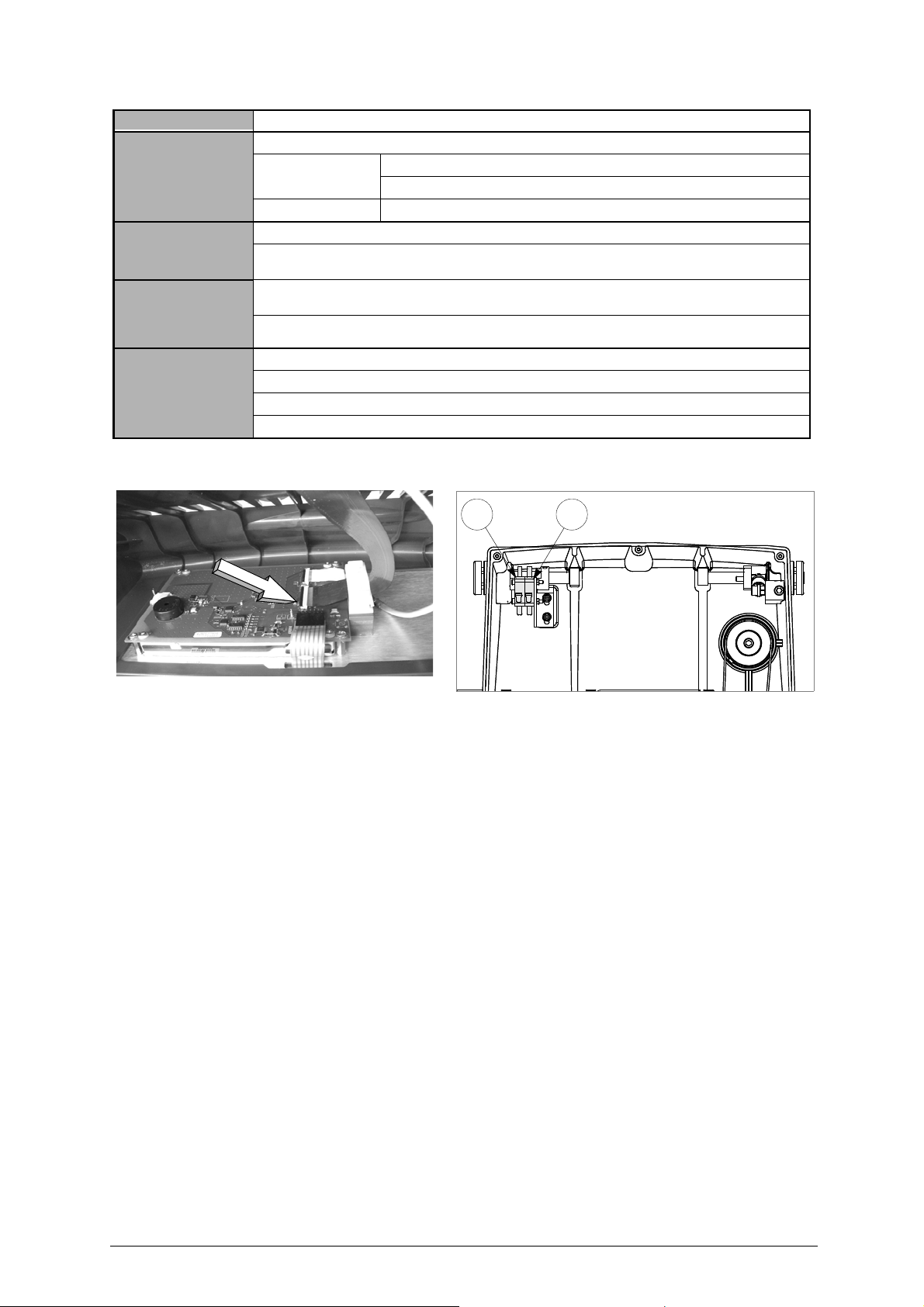
Unocode 399 PLUS Operating manual - English
D3 D4
FAULT PROBABLE CAUSE
The display shows the
message: ‘TEMPERATURE
ALARM - turn the machine
off’.
check that the fan on the back of the key-cutting machine is working:
Not working: a) fan faulty
b) electronic control board faulty
Working: electronic control board faulty
The display shows the
message: ‘I/O POWER
ALARM – check fuse F4”.
The display shows the
message: ‘DIGITAL OUTLET
PROTECTION ALARM - turn
the machine off’.
The display shows the
message: ‘CUTTER MOTOR
ALARM check fuse F1
’
.
a) fuse F4 on the electronic control board faulty.
b) short circuit on inlets or outlets. To find which inlet or outlet is causing the error message, disconnect the J4-5-7-812-14-15-20 connectors one at a time and check each time whether the alarm disappears.
a) short circuit on the outlets. To find which outlet is causing the error message, disconnect the J4-5 connectors one at
a time and check each time whether the alarm disappears.
b) internal fault on the electronic control board.
a) fuse F1 on the electronic control board faulty.
b) cutter microswitch on protective cover triggered or disconnected (D4) (fig. 44).
c) cutter motor wiring disconnected.
d) internal fault on the electronic control board.
Fig. 43
Fig. 44
64 Copyright Silca 2016
Page 69
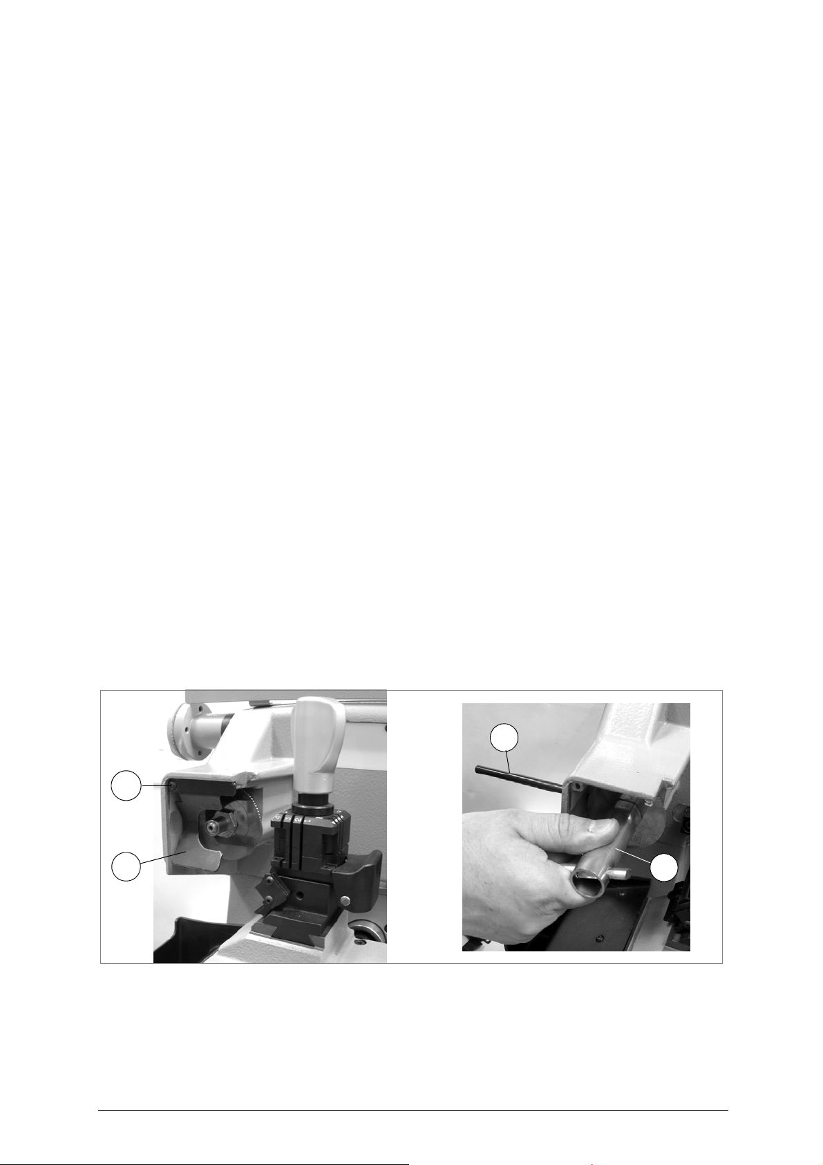
Operating manual - English Unocode 399 PLUS
X1
X
i2
i
7.2 MAINTENANCE OPERATIONS
• Cutter replacement
• Belt replacement and tension adjustment
• Fuse check and replacement
• Electronic circuit board replacement
• Keyboard/display replacement
• Access to back compartment
• Access to bottom compartment
• Sensor replacement
• Photocell replacement
• Battery replacement
• WIN-TRANSFER program for loading/updating the machine program
SAFETY MEASURES TO TAKE WHEN MANAGING ELECTRICAL / ELECTRONIC PARTS
ATTENTION: these operations must be carried out by trained qualified personnel.
Special care must always be taken in replacing electronic components. Observe closely the instructions below.
• Read the instructions carefully before proceeding with replacement.
• Work in an environment with a temperature of 10° to 40° C and relative humidity of
approximately 60%.
• The workbench must be clean, free of foreign bodies and covered in shockproof material.
• Do not use compressed air.
• Do not work with wet or greasy hands.
• Ensure there are no static charges.
7.3 CUTTER REPLACEMENT
1) turn the machine off and unplug it.
2) remove the cutter protective shield (i) by loosening the screw (i2).
3) slide the cutter release rod (X) into the hole located on the left side of the machines cutter shaft chassis (fig. 45).
4) loosen the cutter locking nut (turning it clockwise) with the19 mm socket wrench (X1) provided with the machine.
ATTENTION: the thread is left-handed (reversed.
5) replace the cutter, then tighten the nut (turning it counter-clockwise) and remove the rod from its hole.
6) place the cutters protective shield (i) back into position securing it with the screw (i2).
Fig. 45
ATTENTION: when replacing a worn cutter with a new one or with a re-sharpened cutter consult 5.7 "GAUGING".
Copyright Silca 2016 65
Page 70
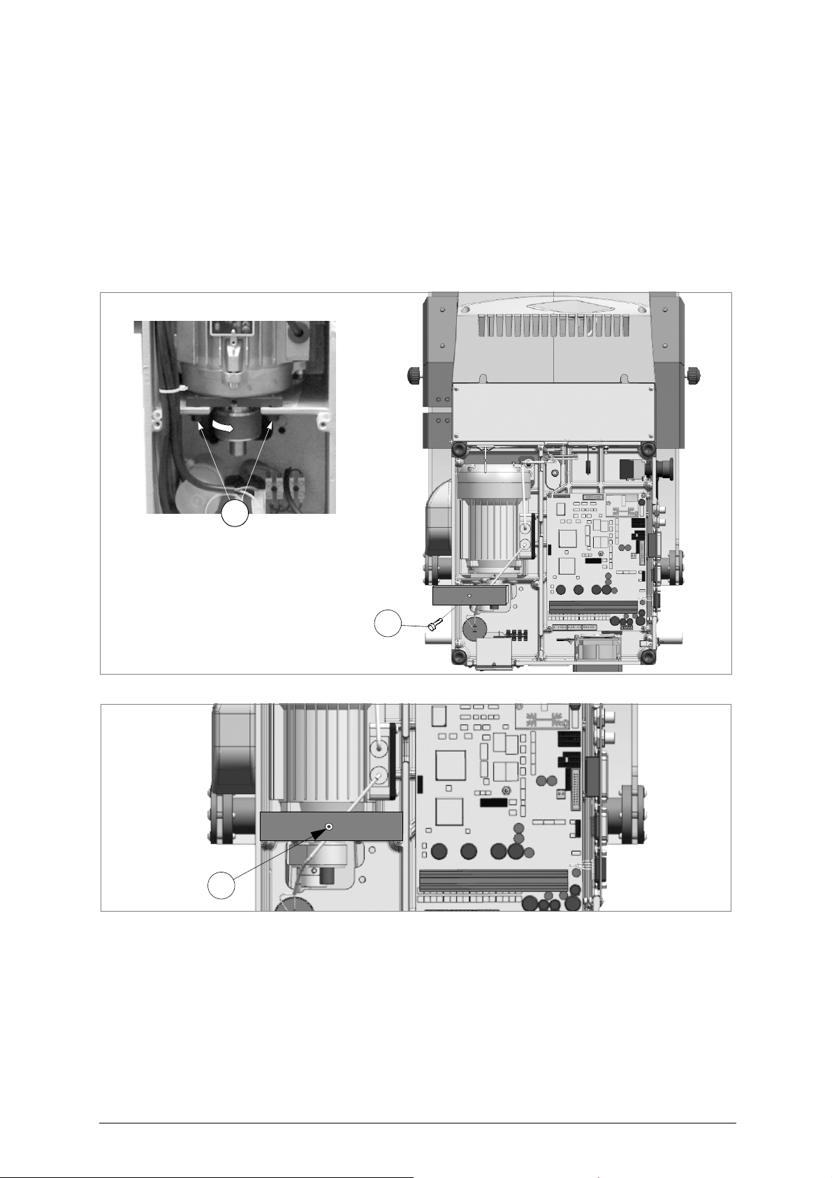
Unocode 399 PLUS Operating manual - English
W
W2
W2
7.4 BELT REPLACEMENT AND TENSION ADJUSTMENT
To replace the belt, proceed as follows
1) turn the machine off and unplug it.
2) remove the back panel (chap.7.8, page 70).
3) remove the bottom panel (chap., page 70).
4) loosen the 4 screws (W) securing the motor (fig. 46).
5) remove the worn belt from the pulleys.
6) fit the new belt onto the pulleys, making sure that the direction of rotation is correct.
7) using the provided belt tension plate and the (W2) screw adjust the belt’s tension by turning the (W2) screw.
8) tighten the 4 (W) screws back into place, securing the motor.
9) remount the back and bottom panel.
:
Fig. 46
Fig. 47
To adjust belt tension proceed as follows
:
1) turn the machine off and unplug it.
2) remove the bottom panel (chap., page 70).
3) loosen the 4 screws (W) securing the motor (fig. 46).
4) using the provided belt tension plate and the (W2) screw adjust the belt’s tension by turning the (W2) screw.
5) tighten the 4 (W) screws back into place, securing the motor.
6) remount the bottom panel.
66 Copyright Silca 2016
Page 71
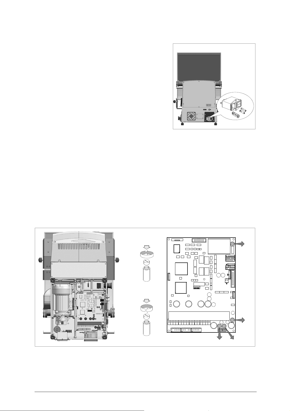
Operating manual - English Unocode 399 PLUS
F1
10A
F4
2A
6.3A
F3
4A
F2
F4
F3
F1
F2
to open
to close
electronic circuit board
7.5 CHECKING AND/OR REPLACING FUSES
Fuses should be checked with a tester (ohmmeter, multimeter, etc.) as
they may appear to be in good condition even when they are electrically
faulty. Fuses must always be replaced with the same amperage and type
(rapid or delayed), as indicated in this manual.
There are 6 fuses in the
•2
fuses: 4 Amps rapid
located next to the power socket on the back of the machine, next to the
main switch
(fig. 48).
surges and/or spikes in the electricity supply.
To check and/or replace the fuses proceed as follows
1) turn the machine off and unplug it from its power supply cable.
2) use a flat screwdriver to open the flap covering the socket, remove
and check the fuses, replacing them if necessary.
•4
fuses
: F1, F2, F3 e F4
F1: 10 Amps delayed
-
protects the cutter motor and its electronic controls
a.c.)
F2: 6,3 Amps delayed
-
protects the step motors and their electronic controls
F3: 4 Amps delayed
-
protects the logic control circuits on the microprocessor board
F4: 2 Amps delayed
-
protects the digital output circuits for the low voltage controls and the sensor inlets
Situated on the electronic circuit board inside the base of the machine
To check and/or replace the fuses proceed as follows
1) turn the machine off and unplug it from its power supply cable.
2) remove the bottom panel (chap., page 70).
3) check and, if necessary, replace the fuses in the way described below:
to remove the fuse
- press the fuse cap with your fingers and turn it counter clockwise.
To fit the new fuse
- carefully position the fuse back into place, then gently press the fuse cap downwards turning it clockwise.
UNOCODE 399 PLUS.
(230V)
These fuses protect the machine from power
:
:
:
Fig. 48
(230V
(+32V d.c.)
(+5V d.c.)
(+24V d.c.)
(fig. 49),
protecting the board from short circuits.
:
Fig. 49
Copyright Silca 2016 67
Page 72
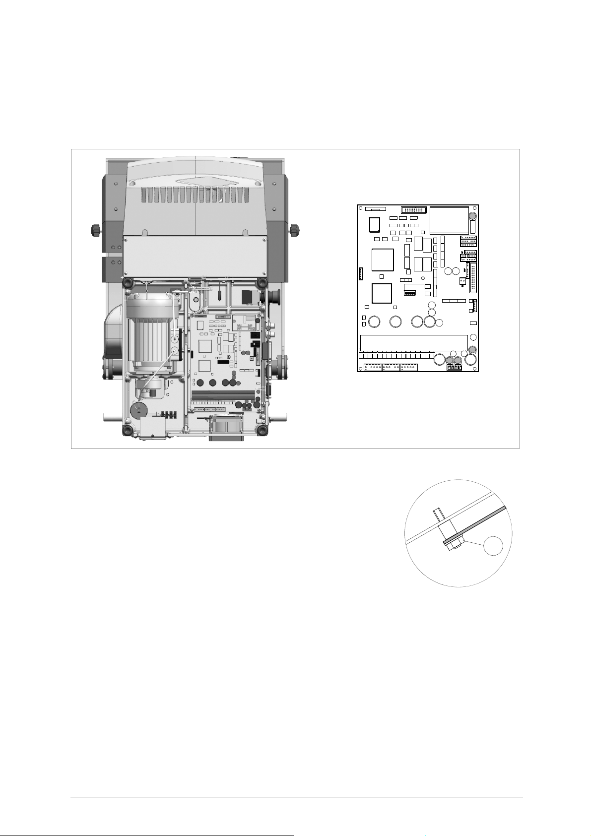
Unocode 399 PLUS Operating manual - English
F1
10A
F4
2A
6.3A
F3
4A
F2
electronic circuit board
Y1
7.6 ELECTRONIC CIRCUIT BOARD REPLACEMENT
Proceed as follows:
1) turn the machine off and unplug it from its power supply cable.
2) remove the bottom panel (ch., page 70).
3) disconnect all cable connectors from the electronic circuit board (fig. 50).
Fig. 50
4) take the electronic circuit board off by unscrewing the (Y1) nuts off (fig. 51).
5) mount the new electronic circuit board and re-connect all cables (all cable
connections are polarised therefore cannot be connected incorrectly).
6) re-fit the bottom panel and re-position the machine on its workbench.
7) turn the machine on and launch the WIN-TRANSFER program (chap.7.13, page
75).
Fig. 51
68 Copyright Silca 2016
Page 73
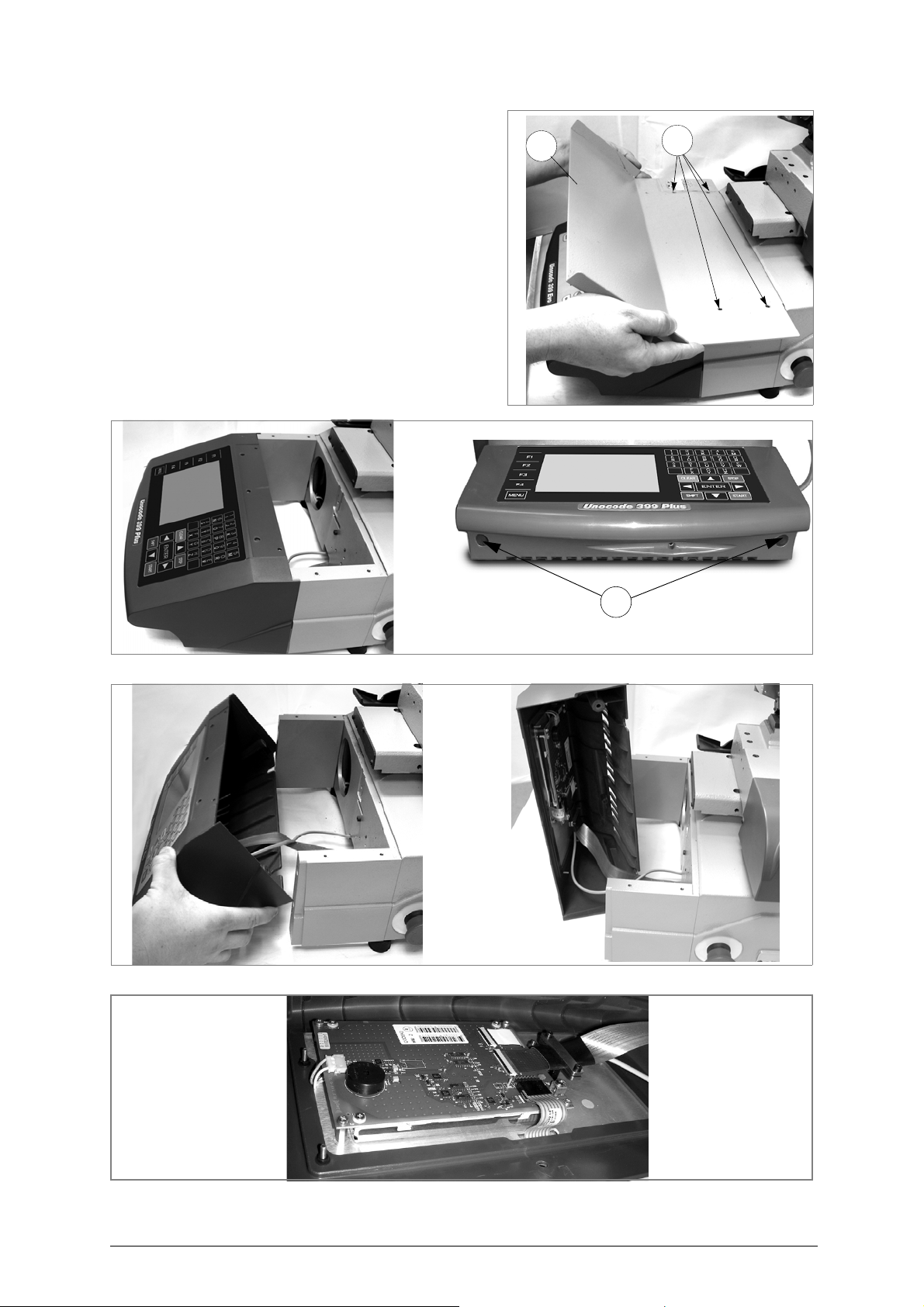
Operating manual - English Unocode 399 PLUS
W4
W3
B1
7.7 KEYBOARD/DISPLAY REPLACEMENT
1) turn the machine off and unplug it from its power supply cable.
2) loosen the 4 screws (W4) and remove the support (W3).
3) remove the display’s support, by unscrewing the 2 (B1)
fixing screws (fig. 53 and fig. 54).
4) detach the flat cable and ground wire from the keyboard
(fig. 55).
5) unscrew the keyboard’s fixing nuts and remove the
keyboard from its support.
6) fit the new keyboard/display, repeating the operations
described above, backwards.
Fig. 52
Fig. 53
Fig. 54
Fig. 55
Copyright Silca 2016 69
Page 74
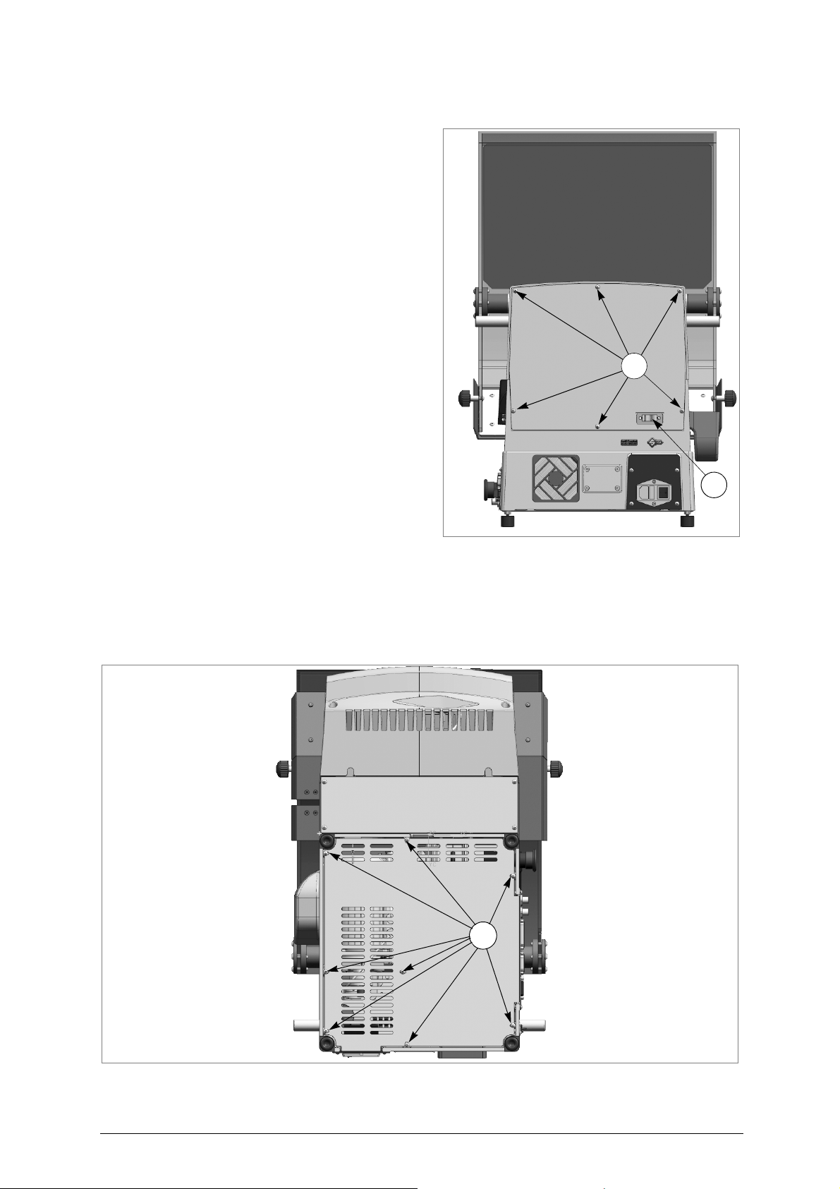
Unocode 399 PLUS Operating manual - English
M1
U2
L1
7.8 ACCESS TO BACK COMPARTMENT
To gain access to the back compartment, proceed as
follows
:
1) turn the machine off and unplug it from its power supply
cable.
2) remove the vacuum system’s connector (U2) (fig. 7.9).
3) unscrew the 6 (M1) screws that secure the back panel
(fig. 7.9) thus removing it.
Fig. 56
7.9 ACCESS TO BOTTOM COMPARTMENT
To gain access to the bottom compartment, proceed as follows
1) turn the machine off and unplug it from its power supply cable.
2) remove the vacuum system’s connector (U2) (fig. 7.9).
3) turn the machine on its back side.
4) remove the machine’s bottom panel by unscrewing the 8 (L1) screws.
:
Fig. 57
70 Copyright Silca 2016
Page 75
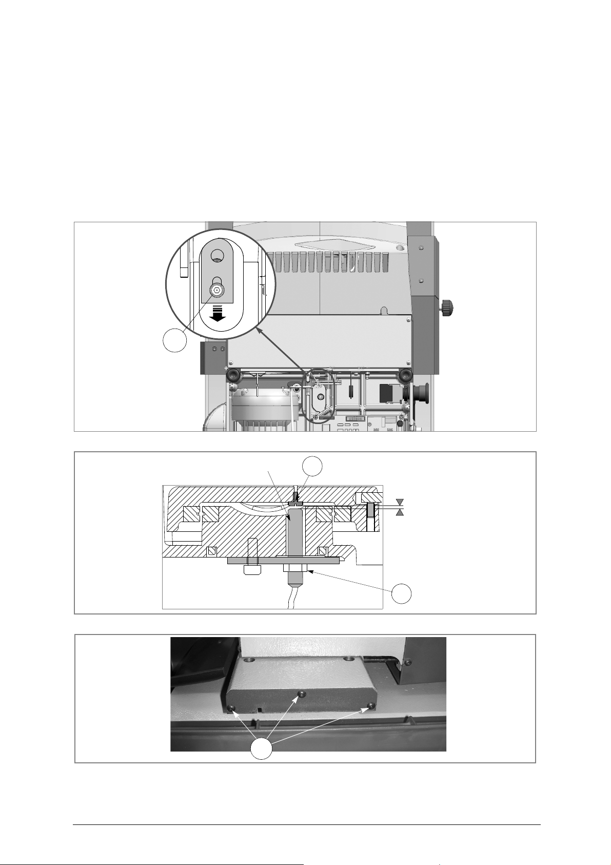
Operating manual - English Unocode 399 PLUS
C3
0,1 - 0,4 mm
L2
X axis sensor
L3
B4
7.10 SENSOR REPLACEMENT
X
AXIS SENSOR REPLACEMENT
1) turn the machine off and unplug it from its power supply cable.
2) remove the bottom panel (chap. "To gain access to the bottom compartment, proceed as follows:").
3) disconnect the X axis sensor’s connector from the electronic circuit board (fig. 58).
4) loosen the (L3) nut. Unscrew the sensor from the plate and remove (fig. 59).
5) remove the front cover on the (X axis) lower carriage by unscrewing the 3 (B4) screws (fig. 60).
6) fit the new sensor in position, tightening it until it almost touches the (L2) screw (fig. 59) thus securing it with the (L3) nut.
7) connect the sensor’s connector to the electronic circuit board.
8) remount the bottom panel and front cover.
Fig. 58
Fig. 59
Fig. 60
Copyright Silca 2016 71
Page 76
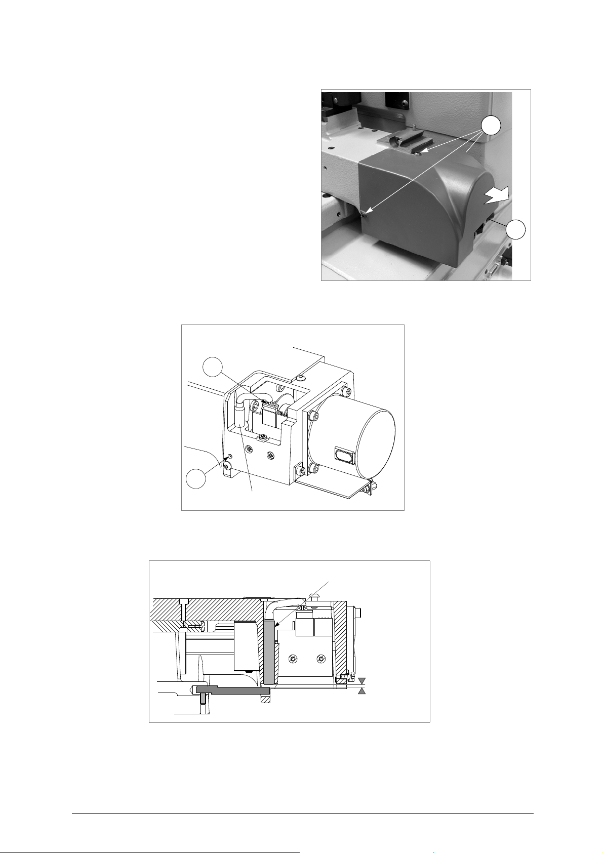
Unocode 399 PLUS Operating manual - English
B5
J1
M3
M2
Y axis sensor
Y axis sensor
0,1 - 0,4 mm
Y
AXIS SENSOR REPLACEMENT
1) turn the machine off and unplug it from its power supply
cable.
2) raise the protective shield.
3) disconnect the (J1) Y axis cable from the carriage (fig. ).
4) remove the Y axis carriage cover by unscrewing the 3
(B5) locking screws and pull the cover in the direction
shown in fig. .
5) disconnect the (M3) sensor’s connector (fig. 62).
6) slightly loosen the (M2) grub screw with the provided
allen key.
7) remove the faulty sensor and replace it with a new one.
Screw it in until it almost touches the underlying rod (fig.
63). Tighten the (M2) grub screw to lock the sensor into
place.
Fig. 61
8) connect the (M3) sensor’s connector.
9) replace the Y axis carriage cover.
10) connect the (J1) Y axis connecting wire to the carriage.
Fig. 62
Fig. 63
72 Copyright Silca 2016
Page 77
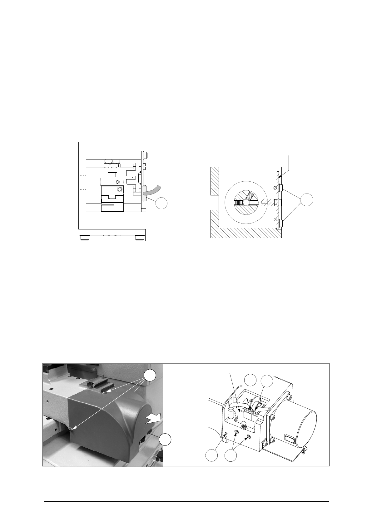
Operating manual - English Unocode 399 PLUS
X axis photocell card
G
G5
K
M2
J
J2
Y axis photocell card
B5
J1
7.11 PHOTOCELL REPLACEMENT
REPLACING THE X AXIS PHOTOCELL
1) turn the machine off and unplug it from its power supply cable.
2)
remove the back panel
3)
unscrew the 2
4)
disconnect the
5)
connect the photocell cable to the new photocell card
6)
replace the photocell in position securing it with the
7)
remount the back panel
8)
plug the machine back in and turn it on
9)
proceed with machine settings
(chap.7.8 "Access to back Compartment").
(G)
screws
that
secure the photocell card and remove
(G5)
photocell cable
.
(fig. 64).
.
(chap.5.8.7 "MACHINE ZERO POINTS", page 46).
.
(G)
screws
.
.
Fig. 64
REPLACING THE Y AXIS PHOTOCELL
1) turn the machine off and unplug it from its power supply cable.
2) disconnect the (J1) Y axis cable from the carriage (fig. 65).
3) remove the Y axis carriage cover by unscrewing the 3 (B5) locking screws and pull the cover in the direction shown in fig. 65.
4) disconnect the (J2) photocell cable and (J) sensor cable (fig. 65).
5) unscrew the 2 (K) screws that hold the photocell card and remove it from the carriage.
6) place the new photocell card in the carriage and tighten the 2 (K) supporting screws.
7) reconnect both the photocell and sensor cables.
8) remount the Y axis protective cover.
9) connect the (J1) Y axis cable back on the carriage.
10)
plug the machine back in and turn it on
11)
proceed with machine settings
.
(chap.5.8.7 "MACHINE ZERO POINTS", page 46).
Fig. 65
Copyright Silca 2016 73
Page 78
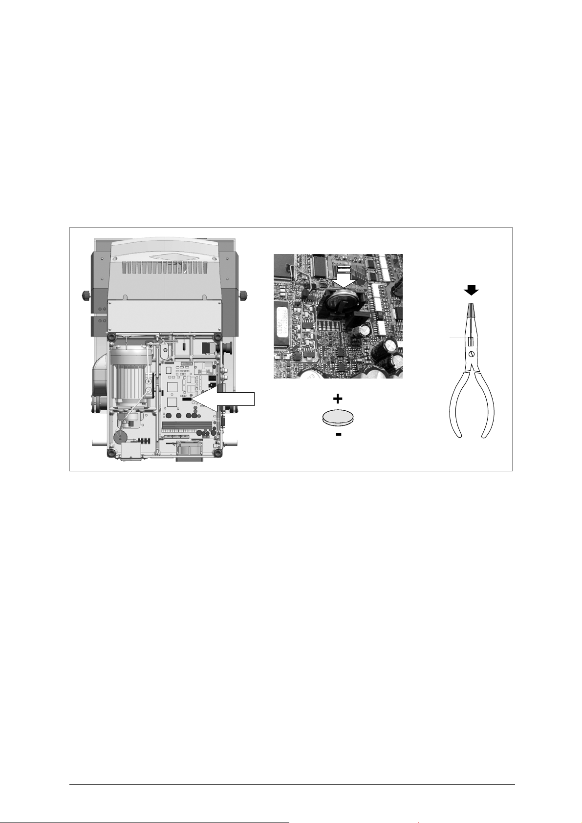
Unocode 399 PLUS Operating manual - English
insulated points
with adhesive tape
7.12 BATTERY REPLACEMENT
Replacing the battery is a simple operation but must be carried out with care.
1) Disconnect the power lead from the key-cutting machine.
2) Gain access to the bottom compartment.
3) Use pliers with insulated tips to grip the battery and pull it out, taking care to push towards the pressure tab to remove from
its shaped housing.
4) Use the pliers with insulated tips to introduce the new battery, inclining it and pushing against the tab to help it enter the shaped
housing.
5) Close up the machine and connect to the mains.
6) Reconfigure the date and time on the machine (chap.5.9, page 52).
ATTENTION:RISK OF EXPLOSION IF BATTERY IS REPLACED BY AN INCORRECT TYPE.
DISPOSE OF USED BATTERIES ACCORDING TO THE INSTRUCTIONS (chap.8 "DISPOSAL", page 76).
Fig. 66
74 Copyright Silca 2016
Page 79

Operating manual - English Unocode 399 PLUS
7.13 WIN-TRANSFER P
The machine is supplied with an internal program already lo aded and tested in our wo rkshops. The
user therefore does not need to carry out any operations.
Only in the situations described below can the WIN-TRANSFER program b e used to re-start the
machine.
The following is a list of situations where the use of the WIN-TRANSFER program is required.
• Replacement of the electronic board (see chap. 7.6, page 68) or loss of the
internal machine program.
1) replace the board with a new one, if necessary.
2) install on your personal computer the latest version received of the WinTransfer program.
3) read the serial number on the data plate on the back of the machine (ch.5.9, page 52) and enter on the machine.
4) gauge the machine according to the instructions in the manual, as follows:
-
gauge as explained in chapter
the user’s manual
-
first gauge the V100 clamp
- continue with the gauging of remaining jaws used.
At this point the machine is set up and ready for operation
• SILCA update for the program or machine data
1)
Install the WinTransfer Program update on your personal comp uter, followin g the instructions in the
program
.
ROGRAM FOR LOADING/UPDATING THE INTERNAL MACHINE PROGRAM
5.8.7 "MACHINE ZERO POINTS" and chap.5.7.1 "Calibrate STANDARD JAWS"”
.
(chap. 5.7.1, page 41).
.
in
Copyright Silca 2016 75
Page 80

Unocode 399 PLUS Operating manual - English
8 DISPOSAL
For correct disposal please refer to current standards.
INFORMATION FOR USERS OF PROFESSIONAL EQUIPMENT
From "Actuation of Directive 2012/19/EU regarding Waste Electricaland Electronic
Equipment (WEEE)"
The symbol of a crossed waste bin found on equipment or its packing indicates that at the end of the
product’s useful life it must be collected separately from other waste so that it can be properly treated
and recycled.
In particular, separate collection of this professional equipment when no longer in use is organised
and managed:
a) directly by the user when the equipment was placed on the market before 31 December 2010 and the
user personally decides to eliminate it without replacing it with new equivalent equipment designed for
the same use;
b) by the manufacturer, that is to say the subject which was the first to introduce and market new equip-
ment that replaces previous equipment, when the user decides to eliminate equipment placed on the
market before 31 December 2010 at the end of its useful life and replace it with an equivalent product
designed for the same use. In this latter case the user may ask the manufacturer to collect the existing
equipment;
c) by the manufacturer, that is to say the subject which was the first to introduce and market new equip-
ment that replaces previous equipment, if it was placed on the market after 31 December 2010;
With reference to portable batteries/accumulators, when such products are no longer in use the user
shall take them to suitable authorised waste treatment facilities.
Suitable separate collection for the purpose of forwarding discarded equipment and batteries/
accumulators for recycling, treatment or disposal in an en vironmentally friendly way helps to avoid
possible negative effects on the environment and human health and encourages re-use and/or
recycling of the materials making up the equipment.
To remove batteries/accumulators, consult the manufacturer’s specific instructions: (see relevant
chapter in the users’ manual)
The sanctions currently provided for by law shall apply to users who dispose of equipment,
batteries and accumulators in unauthorised ways.
.
76 Copyright Silca 2016
Page 81

Operating manual - English Unocode 399 PLUS
9 ASSISTANCE
Silca provides full service to purchasers of the UNOCODE 399 PLUS key-cutting machine. To ensure
complete safety to the operator and machine, any job not specified i n this manual should only be
carried out by the manufacturer or recommended Silca Service Centres.
On the back cover of this manual is a list of the manufacturer’s addresses; listed below are the
addresses of specialized service centres.
9.1 HOW TO REQUEST SERVICE
The guarantee attached to the UNOCODE 399 PLUS ensures free repairs or repl acemen ts of faul ty
parts within 24 months of the date of purchase. All other service calls must be arranged by the
customer with Silca or specialized Silca service centres.
Copyright Silca 2016 77
Page 82

Page 83
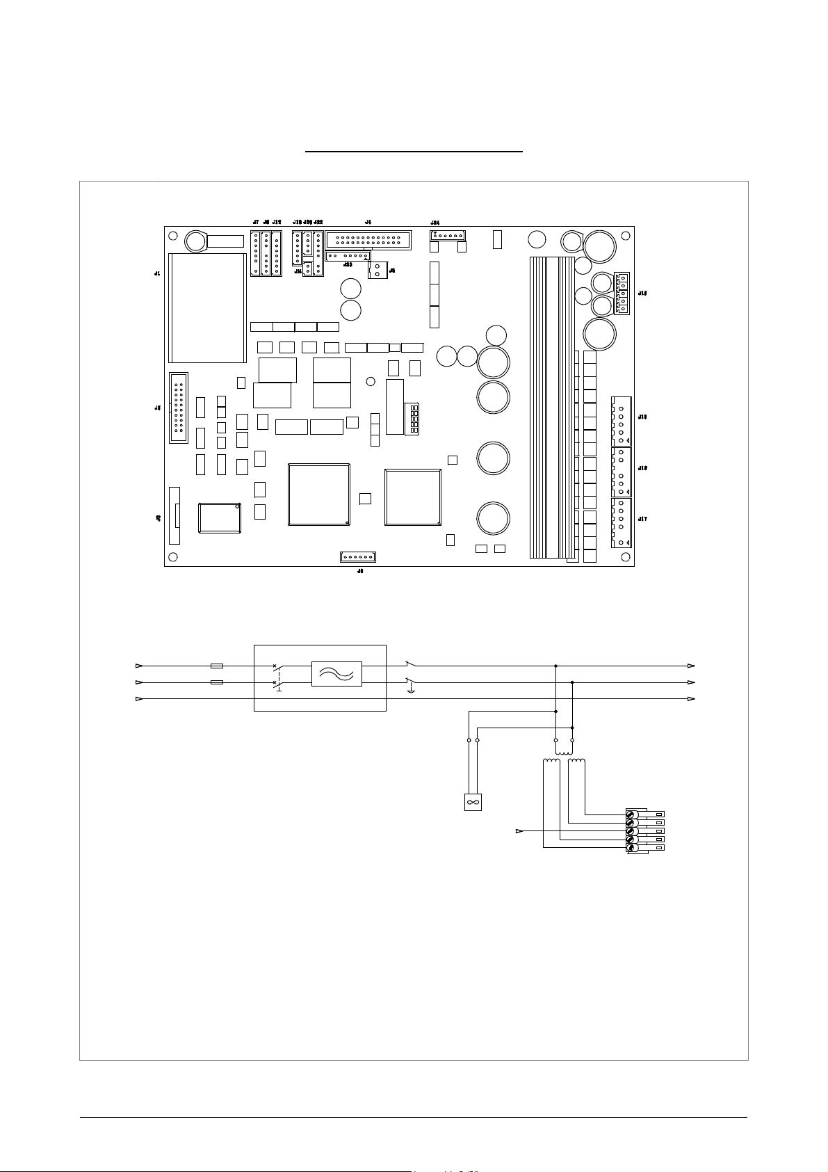
Operating manual - English UNOCODE 399 PLUS
F2
6.3A
F3
4A
F1
10A
F4
2A
P
U
L
S
A
N
T
E
E
M
E
R
G
E
N
Z
A
E
M
E
R
G
E
N
C
Y
B
U
T
T
O
N
P
O
U
S
S
O
I
R
D
U
R
G
E
N
C
E
'
P
U
L
S
A
D
O
R
D
E
E
M
E
R
G
E
N
C
I
A
N
O
T
S
T
O
P
T
A
S
T
E
2
3
0
V
-
5
0
H
z
I
N
T
E
R
R
U
T
T
O
R
E
+
F
I
L
T
R
O
S
W
I
T
C
H
+
F
I
L
T
E
R
I
N
T
E
R
R
U
P
T
E
U
R
+
F
I
L
T
R
E
I
N
T
E
R
R
U
P
T
O
R
+
F
I
L
T
R
O
S
C
H
A
L
T
E
R
+
F
I
L
T
E
R
F
4
A
L
GND
N
1 24 Vac
V
E
N
T
I
L
A
T
O
R
E
F
A
N
V
E
N
T
I
L
A
T
E
U
R
V
E
N
T
I
L
A
D
O
R
V
E
N
T
I
L
A
T
O
R
T
R
A
S
F
O
R
M
A
T
O
R
E
T
R
A
N
S
F
O
R
M
E
R
T
R
A
N
S
F
O
R
M
A
T
E
U
R
T
R
A
N
S
F
O
R
M
A
D
O
R
T
R
A
N
S
F
O
R
M
A
T
E
U
R
GND
3
5
4
2
GND
18 Vac
18 Vac
24 Vac
L1
J 16
GND
N1
UNOCODE 399 PLUS
ELECTRICAL DIAGRAMS
Copyright Silca 2016
Appendix - I
Page 84
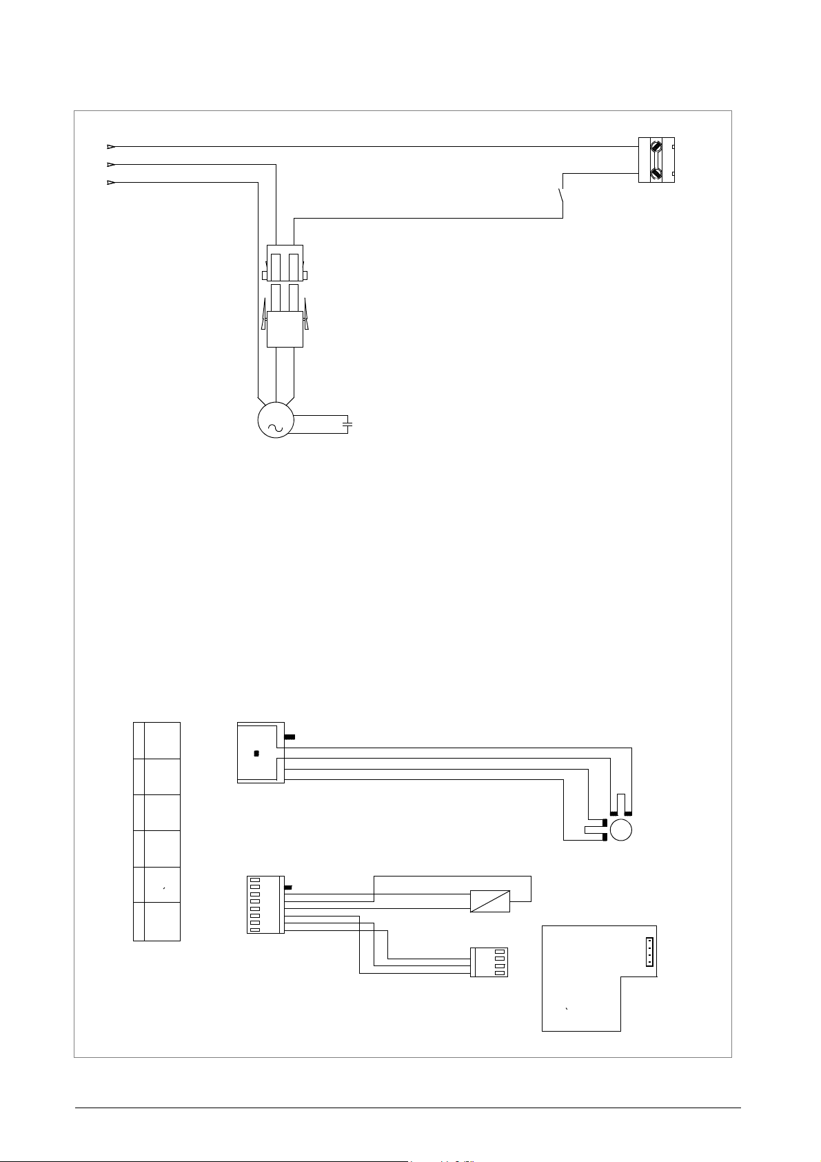
Operating manual - English UNOCODE 399 PLUS
SCHWARZ
2
ORANGE
J17
-
BLAU
BLUE
BRAUN
BROWN
CELLULE PHOTOELECTRIQUE AXE X
PHOTOCELL AXIS X
FOTOZELLE ACHSE X
+
FOTOCELLULA ASSE X
6
MA
5
BI
MA
NERO
BLANC
ROUGE
ORANGE
AR
AZUR
OUT
GND
INFX
B-
INSX
2
-
NEGRO
BI
MX
BRUN
+12V
SENSOR X
1
GI
1
NE
MA
3
BLACK
WHITE
ROJO
WEISS
PP
AZUL
MARRONE
SENSEUR X
SENSORE X
DETECTOR X
3
-
B+
A+
4
ROSSO
RO
RED
4
2
AZ
+24V
NE
1
+12V
NOIR
BIANCO
BLANCO
ANARANJADO
ARANCIO
M
AZ
JA1
SENSOR X
3
2
JA1
INFX
GND
RO
-
7
-
AZ
5
ROT
ORANGE
J7
NE
4
3
GND
AZZURRO
MARRON
4
FOTOCELULA EJE X
1
GND
A-
RO
8
6
MOTORE FRESA
CUTTING TOOL MOTOR
MOTEUR FRAISE
MOTOR FRESA
MOTOR FRASER
8
u
F
M
12
GND
L1
N1
1
2
2
1
J1
MIK
ROSCHALTER SCHUTZ
MICRO
INTERRUPTOR
MICROINTERRUPTEUR ECRA N
MICROSWITCH SHIELD
MICROINTERRUTTORE CA RTER
Appendix - II Copyright Silca 2016
Page 85
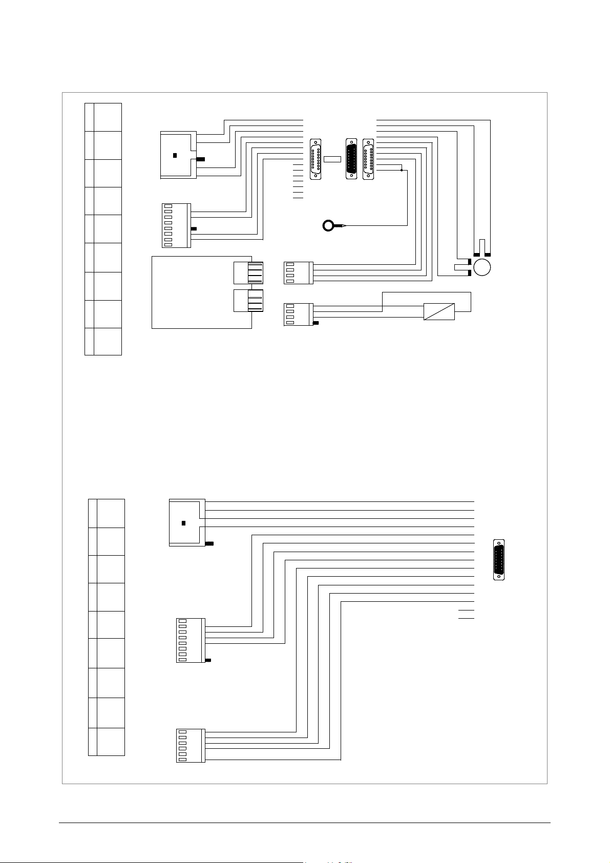
BLANC
NERO
GLEB
GRUN
SCHWARZ
ANARANJADO
AZ
-
ARANCIO
INFY
ROJO
VERT
2
MARRONE
8
AZ
BI
ROSSO
YELLOW
A+
2
SENSOR Y
BLANC
1
ORANGE
AZUL
AZZURRO
FOTOZELLE ACHSE Y
BRUN
GLEB
GRUN
8
GREEN
+24V
4
10
AZZURRO
MARRONE
ORANGE
GND
INSY
BI
2
PP
AZUR
INFB
AZUR
WEISS
GRIS
3
GND
7
AR
15
5
8
5
GND
GND
FOTOCELULA EJE Y
1
AMARILLO
1
-
AR
9
1
5
8
BLAU
1
BI
RO
4
12
GND
JAUNE
GND
GIALLO
RO
2
BIANCO
A
X
I
S
B
NE
VERDE
7
2
RO
BLUE
NEGRO
AZUR
B+
3
YELLOW
4
-
WHITE
VE
GRUN
ANARANJADO
VE
1
5
-
RO
RED
4
1
GI
J19
AZ
AZZURRO
11
13
6
13
9
NE
SCHWARZ
ROJO
MARRON
BIANCO
INSY
2
GI
JAUNE
5
JA3
3
+12V
BLACK
7
GREEN
+24V
VE
BLANCO
BLACK
GRAU
4
J8
MA
1
VE
VERDE
2
OUT
INS
A
X
E
B
BRUN
1
9
VE
5
CELLULE PHOTOELECTRIQUE AXE Y
3
-
J12
MA
BRAUN
+12V
11
INSB
RO
4
2
J18
GND
ROSSO
AZ
3
ORANGE
14
1
9
MA
-
5
NE
WEISS
6
ORANGE
AZ
BLUE
MA
2
B-
ROUGE
B-
4
A
C
H
S
E
B
VERDE
14
12
ORANGE
VERDE
3
1
MY
BLANCO
MA
-
+12V
3
GRIS
9
NE
VERT
1
5
6
15
4
BI
GIALLO
GRIGIO
-
SENSORE Y
ARANCIO
2
8
NE
BRAUN
NE
ROT
4
12
VERT
8
10
AZUL
A-
INFY
6
3
GR
NE
VE
INFB
AZ
+12V
BI
B+
M
DETECTOR Y
10
NERO
4
5
15
8
JA2
ROT
ORANGE
GI
SENSEUR Y
SENSOR Y
15
JA3
6
BROWN
NE
VE
J15
9
PHOTOCELL AXIS Y
3
GREY
+12V
AZUL
NE
+
MARRON
A
S
S
E
B
5
1
6
+24V
7
BI
4
AMARILLO
A-
NOIR
1
1
RO
8
BLAU
NOIR
GND
BLAU
-
NEGRO
4
JA2
9
1
3
11
ROUGE
BROWN
WHITE
A+
RO
RED
VERDE
3
8
BI
5
6
RO
RO
FOTOCELLULA ASSE Y
BLUE
GI
AR
2
VERDE
6
GND
E
J
E
B
1
GREEN
7
GND
INSB
Operating manual - English UNOCODE 399 PLUS
Copyright Silca 2016
Appendix - III
Page 86
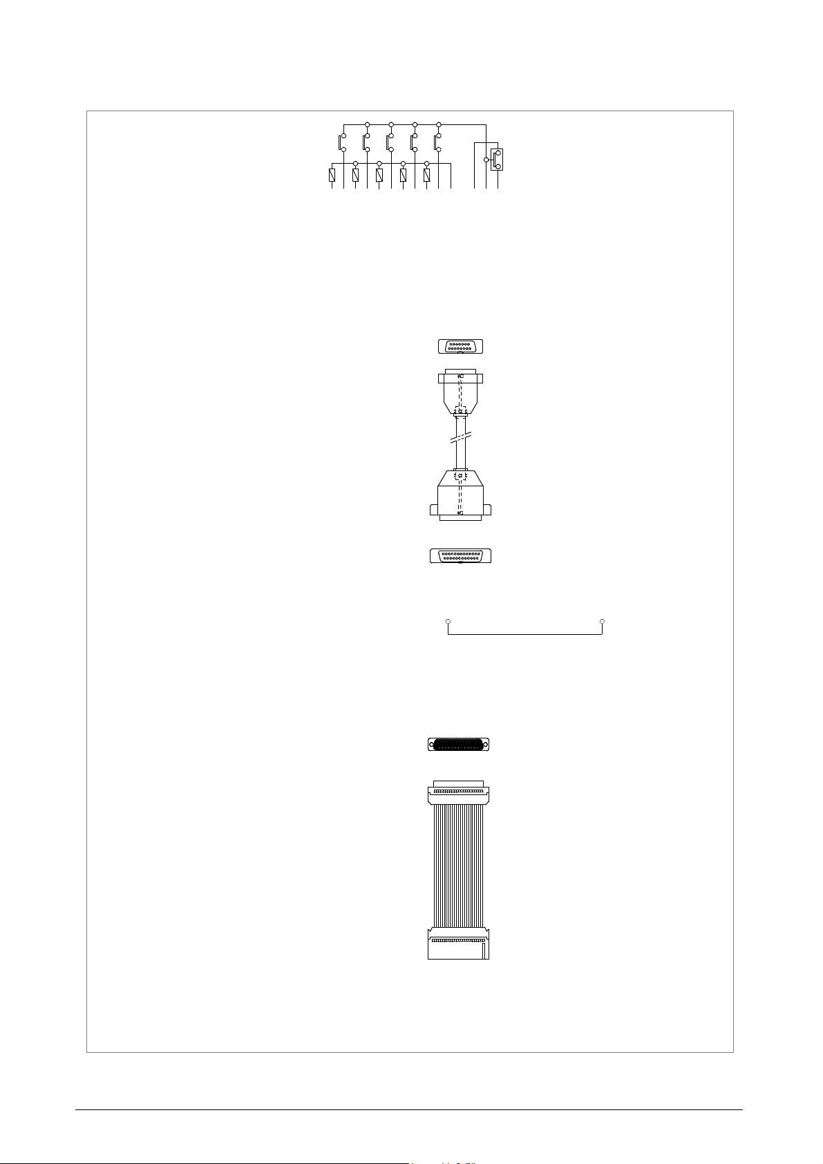
Operating manual - English UNOCODE 399 PLUS
ALIMENTATORE AUTOMATICO
AUTOMATIC FEEDER
ALIMENTATEUR AUTOMATIQUE
ALIMENTADOR AUTOMATICO
AUTOMATISCHE ZUFUHRER
..
8 - ELETTROVALVOLA 1
12 OUT 3
11 OUT 1
7 OUT AUX 1
5 -
4 -
+24V 12
+24V 9
21 -
8
25 SENSORE E
OUT AUX 1 13
IN AUX 2 24
OUT AUX 0 19
1
4
23 ELETTROVALVOLA 4
7 ELETTROVALVOLA 3
9
5 ELETTROVALVOLA 5
15 SENSORE F
8 GND
25 IN AUX 2
13 IN AUX 1
3 SENSORE D
IN 0 1
IN 5 6
13 -
7 -
IN 8 14
IN AUX 1 25
OUT 0 20
14 SENSORE C
10
12 SENSORE B
14 IN 1
23 OUT 0
4 IN6
6 -
IN 7 8
IN 3 4
10 ELETTROVALVOLA 2
1
1
3
1
16 SENSORE B
OUT 2 22
8
2 +24
4 ELETTROVALVOLA 2
6 ELETTROVALVOLA 4
9 GND
21 GND
22 GND
3 IN 4
1 -
IN 1 2
IN 2 3
12 ELETTROVALVOLA 3
2
5
OUT 3 23
3 GND 3
24 ELETTROVALVOLA 5
14
1
3
1
5
9 GND
11 SENSORE D
13 SENSORE E
6 +24V
18 +24V
17 IN 7
1 IN 0
19 +24
+24V 11
IN 6 7
22 -
GND 18
GND 16
OUT 1 21
1 - SENSORE G
24 OUT 2
15 IN 3
10 OUT AUX 0
19 +24V
2 SENSORE G
15 SENSORE C
+24V 10
20 -
11 ELETTROVALVOLA 1
GND 15
IN AUX 3 26
1
4
2 IN 2
5 +24V
20 IN 8
16 IN 5
18 -
17 SENSORE F
IN 4 5
9 GND
2
5
GND 17
J4
1
815714613512411310291
Appendix - IV Copyright Silca 2016
Page 87
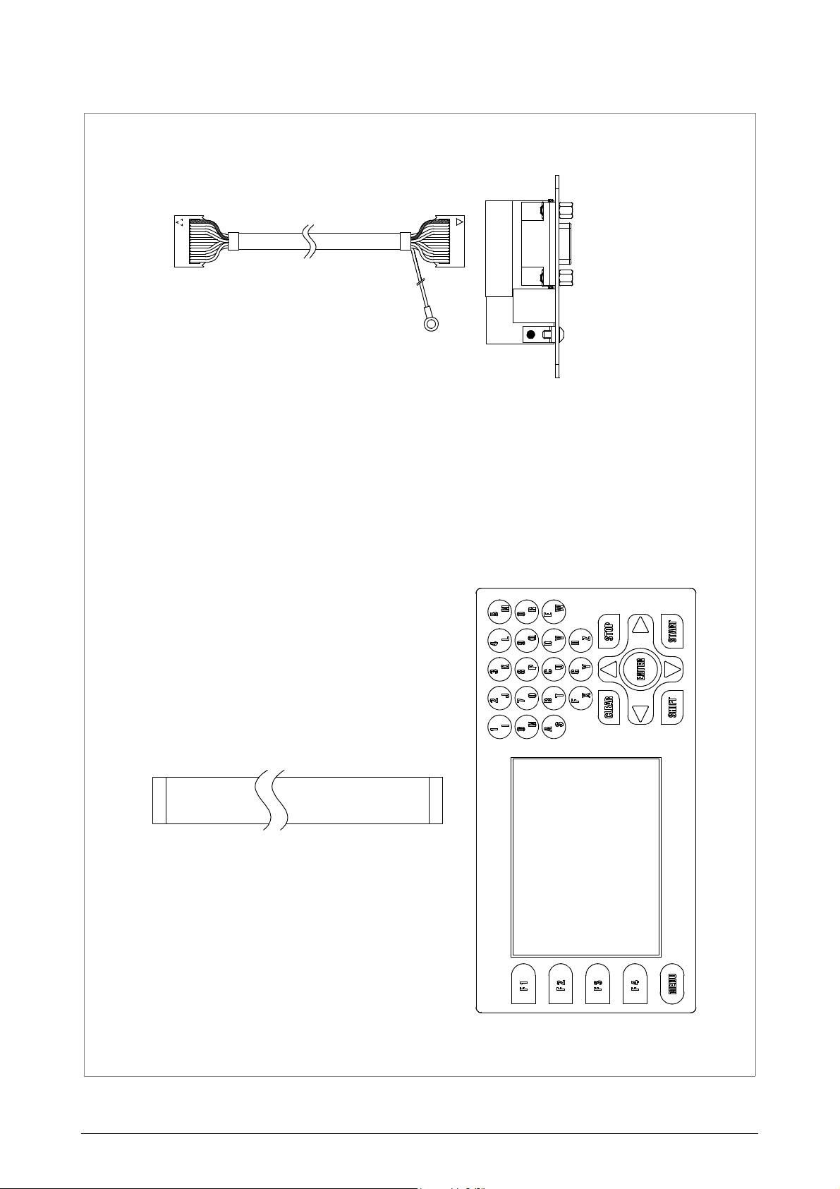
Operating manual - English UNOCODE 399 PLUS
SCHEDA RSR232/USB
FICHE RSR232/USB
J2
CARD RSR232/USB
FICHA RSR232/USB
J3
KARTE RSR232/USB
1
20
20
1
Copyright Silca 2016
Appendix - V
Page 88
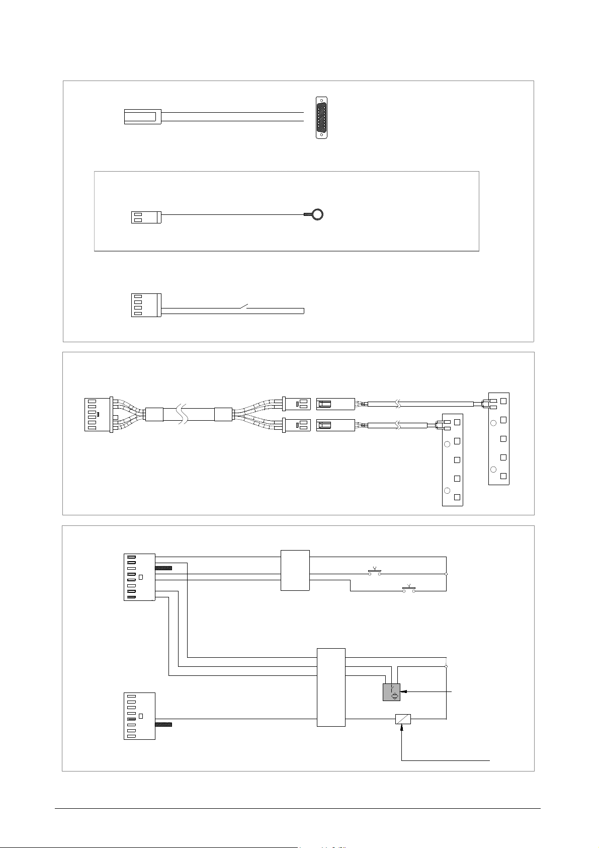
Operating manual - English UNOCODE 399 PLUS
CONTATTO ELETTRICO CHIAVE
4
(IN8)
2
RO
3
MIKROSCHALTER SCHUTZ
MICROINTERRUPTEUR ECRAN
CONTACTO ELETRICO
ELEKTRISCH KONTAKT
GND
1
2
2
J5
1
(IN7)
ELETTROVALVOLA ASPIRAZIONE
1
SUCTION SOLENOID VALVE
8
ELECTROVANNE ASPIRATION
1
GND
9
ELECTROVALVULA ASPIRADOR
15
ELECTROVENTIL SPANEABSAUGANLAGE
9
ELECTRIC CONTACT
INPKEY
GND
MICROSWITCH SHIELD
GND
J20
10
MICROINTERRUTTORE CARTER
NE
24V/1.5A
J14
CONTACT ELECTRIQUE
MICROINTERRUPTOR
NOT ENABLE ON THIS MACHINE
LAMPE LED
LAMPARA LED
J24
LAMPADA LED
LAMPE LED
LED LAMP
Stacker solenoid valve
-
-
-
OUT-AUX3
POLARIZZATORE
-
-
STOP
+24
GND
1
8
J23
START
3
2
1
4
1
3
4
J22
1
8
GND
GND
POLARIZZATORE
IN-AUX0
IN-AUX1
IN-AUX2
IN-AUX3
+24
Input AUX 3
tray filling sensor
Auxiliary output 4
Appendix - VI Copyright Silca 2016
Page 89
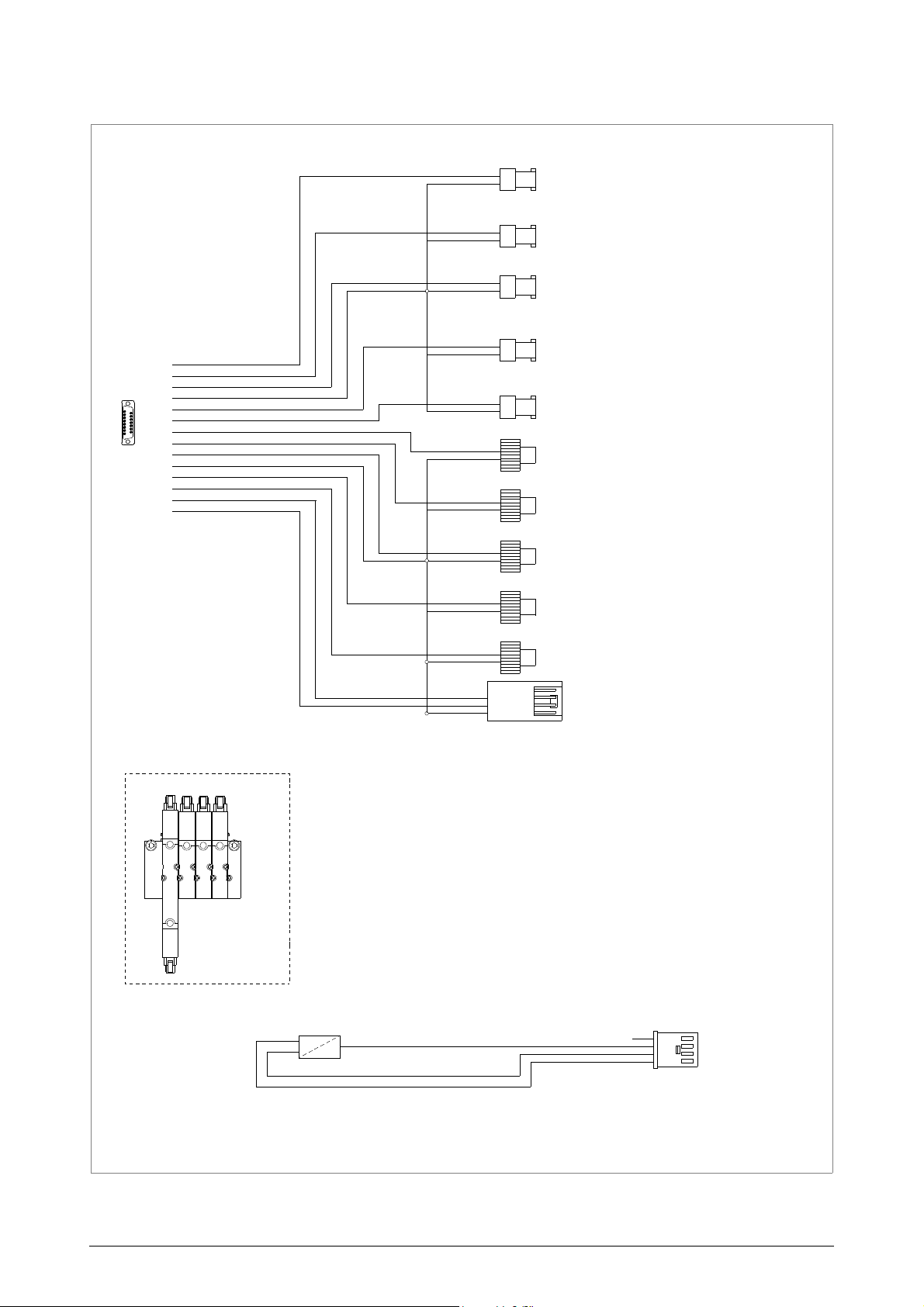
Operating manual - English UNOCODE 399 PLUS
1
5
8
9
1
POS. 8
POS. 4
POS. 7
POS. 3
POS. 6
POS. 5
POS. 15
POS. 14
POS. 13
POS. 9
POS. 12
POS. 11
POS. 2
POS. 1
POS. 10 libero
CLAMP OPEN/CLOSE SOLENOID VALVE
KEY GUIDE PLATE ADVANCEMENT SOLENOID VALVE
KEY GUIDE PLATE BACK SOLENOID VALVE
KEY BACK LIMIT SWITCH D SENSOR
KEY EJECTOR GUIDE PLATE CYLINDER SOLENOID VALVE
GAUGE OPEN/CLOSE SOLENOID VALVE
1
2
3
4
5
RED
BLACK
BLACK
RED
RED
BLACK
BROWN
BLACK
BLUE
BLACK
RED
RED
BLACK
3
OUT
2
4
1
GND
+
SENSORE X
SENSOR X
SENSEUR X
DETECTOR X
SENSOR X
VISTA VALVOLE
PER CONNESIONE
CABLAGGIO
431
2
5
BROWN F
BLUE
BLUE
BROWN C
BLUE
BROWN E
BLUE
BROWN B
BLUE
BROWN D
KEY GUIDE PLATE LIMIT SWITCH E SENSOR
INTERMEDIATE S E N S O R B
KEY GUIDE PLATE LIMIT SWITCH E SENSOR
KEY ADVANCEMENT LIMIT SWITCH C SENSOR
KEY GUIDE PLATE LIMIT SWITCH F SENSOR
OUTPUT 2
AUXILIARY OUTPUT 1
OUTPUT 4
OUTPUT 1
OUTPUT 3
Copyright Silca 2016
Appendix - VII
Page 90
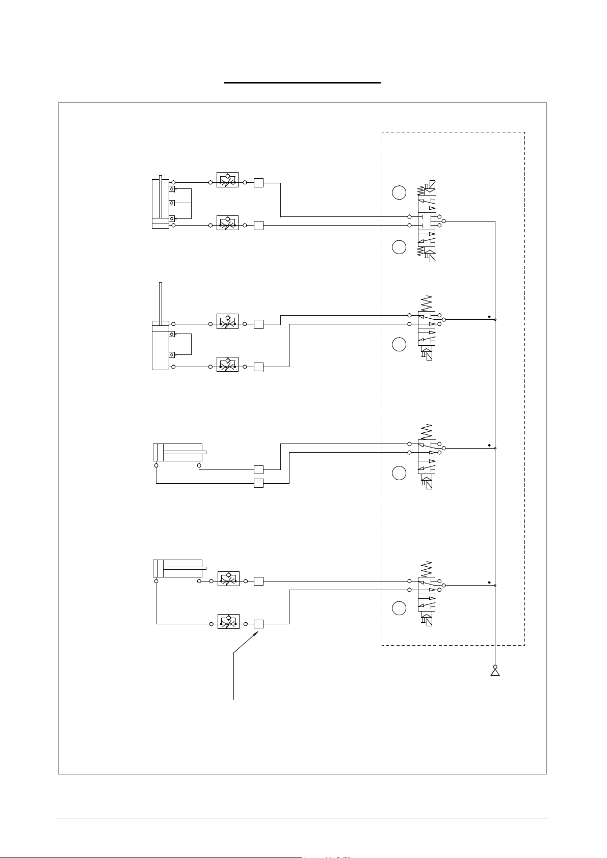
Operating manual - English UNOCODE 399 PLUS
MARCA CAVO
5
4
PNEUMATIC DIAGRAM AUTOMATIC FEEDER - UNOCODE 399 PLUS
Air inlet
4
2
Gauge
3
24
8
3
4
Clamps
sensors
4
3
2
5 1
Key guide plate / Ejector
2
1
3
43
14
Key feeder
14
5
1
2
at 5/6 atm
5
12
14
5
3
5
6
1
sensors
7
1
14
1
2
PENUMATIC DIAGRAMS
Appendix - VIII Copyright Silca 2016
Page 91
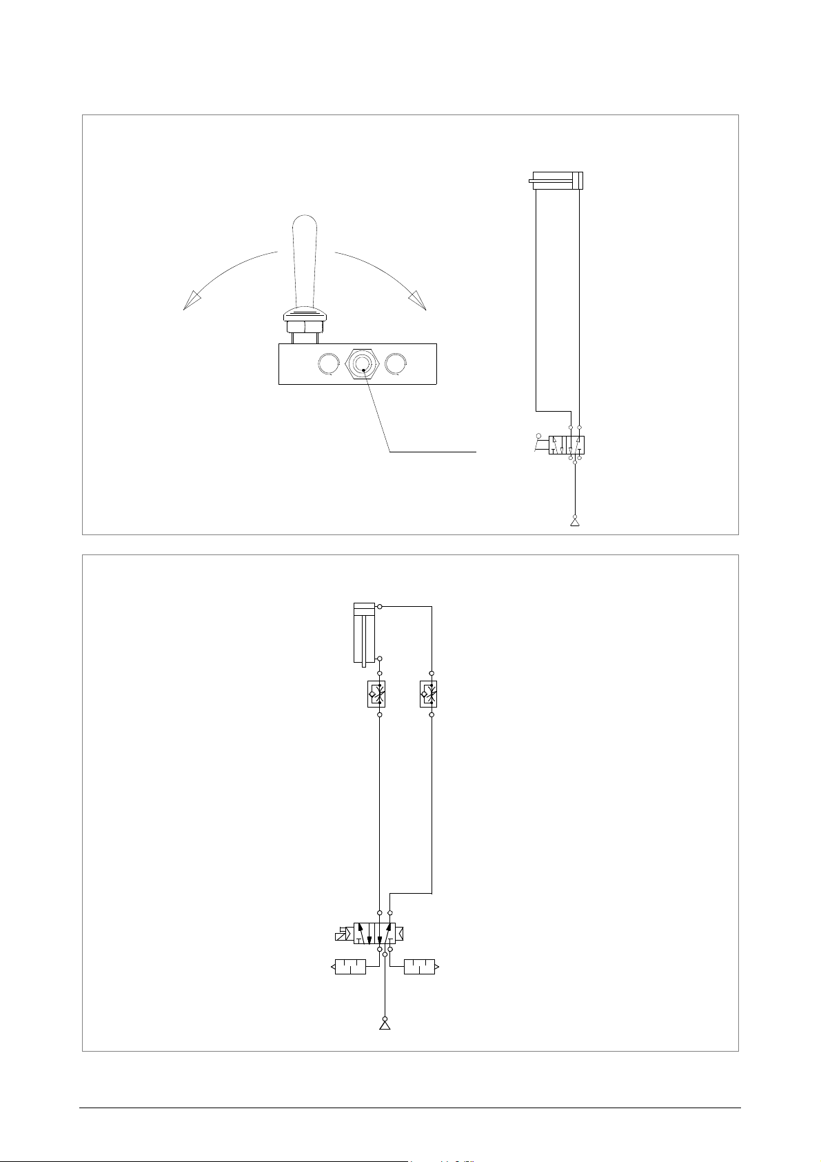
Operating manual - English UNOCODE 399 PLUS
at 5/6 atm
Air inlet
C
L
O
S
E
D
O
P
E
N
CLAMP PNEUMATIC DIAGRAM
AIR INLET
KEY SORTER PNEUMATIC DIAGRAM
at 5/6 atm
Aitr inlet
1
14
4
3
5
2
2
4
Copyright Silca 2016
Appendix - IX
Page 92
VITTORIO VENETO 24/03/2011
CE DECLARATION OF MACHINE COMPLIANCE
SILCA S.p.A. - VIA PODGORA 20 ( Z.I.)
31029 VITTORIO VENETO (TV) - (ITALY)
TEL. 0438 9136 - FAX. 0438 913800
Declares under its own responsibility that the Key-cutting machine model
UNOCODE 399 EVO
complies with the requirements of the following European Directives:
European Union DIRECTIVE 2006/42/CE (Machines)
and with the EN 12100 – 1 / EN 12100 – 2 Standards
European Union DIRECTIVE 2004/108/CE
and with the EN 55022 / EN 55024
EN 61000 – 3 – 2 / EN 61000 – 3 – 3 / EN 62233 : 2008 Standards
European Union DIRECTIVE 2006/95/CE
and with the EN 60950 – 1 / EN 60825 – 1 Standards
Claudio Tomasella of the Silca S.p.A. Research & Development Division is authorized
to create a Technical File.
General Manager Basic Production Center
(Electromagnetic Compatibility)
(Low Voltage) | 08 |
Page 93

SILCA S.p.A.
Via Podgora, 20 (Z.I.)
31029 VITTORIO VENETO (TV)
Phone: +39 0438 9136
Fax +39 0438 913800
E-mail: [email protected]
www.silca.biz
United Kingdom
SILCA Ltd.
Unit 6 Lloyds Court - Manor Royal
CRAWLEY RH10 9QU
Phone: +44 1293 531134
Fax +44 1293 531108
E-mail: [email protected]
www.silcaltd.co.uk
France
SILCA S.A.S.
12, Rue de Rouen
Z.I. de Limay - Porcheville
78440 PORCHEVILLE
Phone: +33 1 30983500
Fax +33 1 30983501
E-mail: [email protected]
www.silca.fr
Germany
SILCA GmbH
Siemensstrasse, 33
42551 VELBERT
Phone: +49 2051 2710
Fax +49 2051 271172
E-mail: [email protected]
www.silca.de
India
MINDA SILCA Engineering Ltd.
Plot no.37, Toy City,
GREATER NOIDA (U.P.) - 201308
Phone: +91 9871397630/31
Fax: +91 120 2351301
E-mail: [email protected]
www.mindasilca.in
North America
U.S.A., Canada, Caribbean Islands
KABA Ilco Corp.
400 Jeffreys Road
Rocky Mount, NC 27804 USA
Phone: 1 800 334 1381 / 1 252 446 3321
Fax: 1 252 446 4702
E-mail: [email protected]
www.ilco.us
Central America
Mexico, Guatemala, Belize, El Salvador,
Honduras, Nicaragua, Costa Rica, Panama
Corporación Cerraiera Alba S.A. de C.V.
Prolongaci
Col.Los reyes, Tultitlán, Estado de México C.P. 54915
ón avenida independencia 14, Bodega 5,
E-mail: [email protected]
Kaba Mexico
Phone: 01 55 5366 7200
www.kabamexico.com
Spain
SILCA KEY SYSTEMS S.A.
C/Santander 73A
08020 BARCELONA
Phone: +34 93 4981400
Fax +34 93 2788004
E-mail: [email protected]
www.silca.es
Netherlands
H. CILLEKENS B.V.
Metaalweg, 4
6045 JB ROERMOND
Phone: +31 475 325147
Fax +31 475 323640
E-mail: [email protected]
www.hcillekens.nl
Brazil
KABA DO BRASIL Ltda
Rua Guilherme Asbahr Neto, 510
São Paulo, SP 04646-001
Phone: +55 11 55454520 / 29
E-mail: [email protected]
www.silcachaves.com.br
Colombia
SILCA SOUTH AMERICA S.A.
Km 1.5 Via Briceño-Zipaquira
Parque Ind. Trafalgar Bodega 3
Tocancipa-Cundinamarca
Phone: +57 1 7366480
Fax +57 1 7366490
www.fl exonsilca.co
 Loading...