

Silca Twister 2 Operating Manual
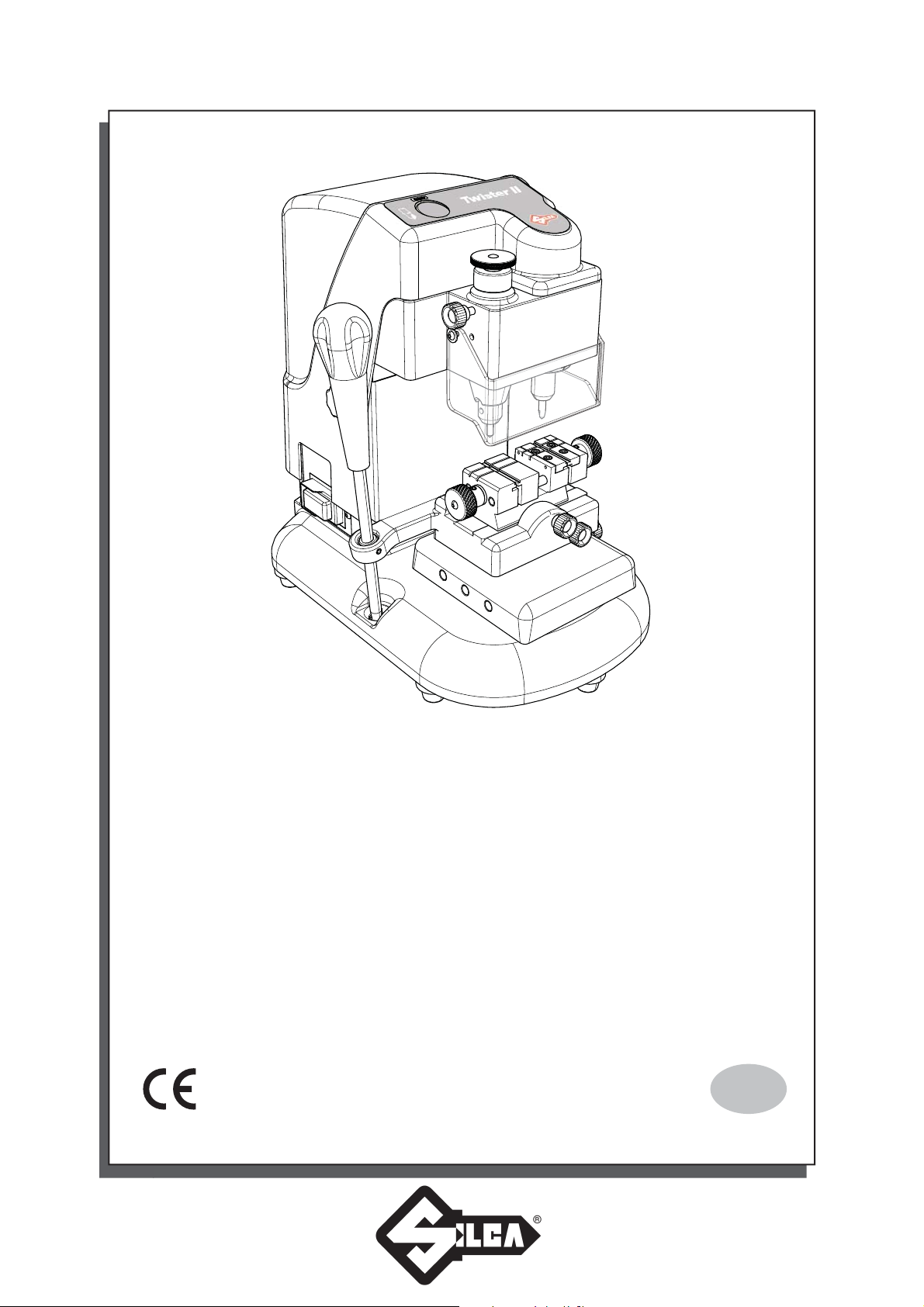
Twister II
Operating Manual
Translation of original instructions
D445476XA
vers. 2.0
EN

© 2015 SILCA S.p.A. - Vittorio Veneto
All rights reserved. No part of this publication may be reproduced or used in any form or by any means (photocopying, microfi lm or other)
without the written permission of Silca S.p.A.
Edition: July 2017
Printed in India
by MINDA SILCA Engineering Ltd.
Plot no.37, Toy City, GREATER NOIDA (U.P.) - 201308
IMPORTANT NOTE: in compliance with current regulations relating to industrial property, we hereby state that the trade-marks or trade names
mentioned in our documentation are the exclusive property of authorized manufacturers of locks and users.
manufacturers of locks and users.
Said trade-marks or trade names are shown only for the purposes of information so that any lock for which our keys are made can be rapidly identifi ed.

INDEX
GUIDE TO THE MANUAL ...................................................................................................................1
GENERAL INTRODUCTION ...............................................................................................................2
1 TRANSPORT ........................................................................................................................................4
1.1 PACKING ...................................................................................................................................4
1.2 TRANSPORT ..............................................................................................................................4
1.3 UNPACKING ...............................................................................................................................4
1.4 HANDLING THE MACHINE ........................................................................................................4
1.5 SAFETY ......................................................................................................................................4
2 MACHINE DESCRIPTION ....................................................................................................................5
3 WORKING PARTS ................................................................................................................................7
3.1 TECHNICAL DATA .....................................................................................................................8
3.2 ELECTRIC CIRCUIT ...................................................................................................................9
4 ACCESSORIES PROVIDED .............................................................................................................10
5 MACHINE INSTALLATION AND PREPARATION ..............................................................................11
5.1 CHECKING FOR DAMAGE ......................................................................................................11
5.2 ENVIRONMENTAL CONDITIONS ............................................................................................11
5.3 POSITIONING .........................................................................................................................11
5.4 DESCRIPTION OF WORK STATION .......................................................................................11
6 MACHINE REGULATION AND UTILIZATION ....................................................................................12
6.1 FITTING AND REGULATING THE TOOLS ..............................................................................12
6.2 CALIBRATION OF CUTTER AND TRACER ............................................................................13
7 CUTTING OPERATIONS ...................................................................................................................14
7.1 KEY CUTTING .........................................................................................................................14
7.2 CUTTING KEYS WITH KEY STOPS ........................................................................................14
7.3 CUTTING KEYS WITHOUT KEY STOPS ................................................................................15
7.4 INSERTING THE SPRING SYSTEM FOR DIMPLE KEYS ......................................................15
7.5 CUTTING LASER (SIDEWINDER ) TYPE KEYS .....................................................................15
7.6 CUTTING NARROW-BLADE LASER (SIDEWINDER) TYPE KEYS
7.7 CUTTING KEYS FOR FICHET .................................................................................................16
8 MAINTENANCE ..................................................................................................................................17
8.1 REPLACING THE BELT AND ADJUSTING TENSION .............................................................17
8.2 REPLACING THE LAMP .........................................................................................................18
8.3 CHECKING AND REPLACING THE FUSES ............................................................................18
8.4 REPLACING THE JAWS ON RIGHT-HAND CLAMP ...............................................................19
8.4.1 REPLACING LEFT JAW ................................................................................................19
8.4.2 REPLACING RIGHT JAW ..............................................................................................19
9 DISPOSAL ..........................................................................................................................................20
10 AFTER-SALES SERVICE ..................................................................................................................21
10.1 HOW TO REQUEST SERVICE ................................................................................................21
....................................16

Operating manual - English Twister II
GUIDE TO THE MANUAL
This manual has been produced to serve as a guide for users of the TWISTER II key-cutting machine. Read it
carefully; it is essential if you wish to operate your machine safely and effi ciently.
Consultation
The contents of the manual are divided into sections relating to:
-
Transport and handling ...............................................................................................Ch. 1
-
Description of machine and safety devices ................................................................Ch. 2-3-4
-
Proper use of machine ...............................................................................................Ch. 5-6-7
-
Maintenance ...............................................................................................................Ch. 8-9-10
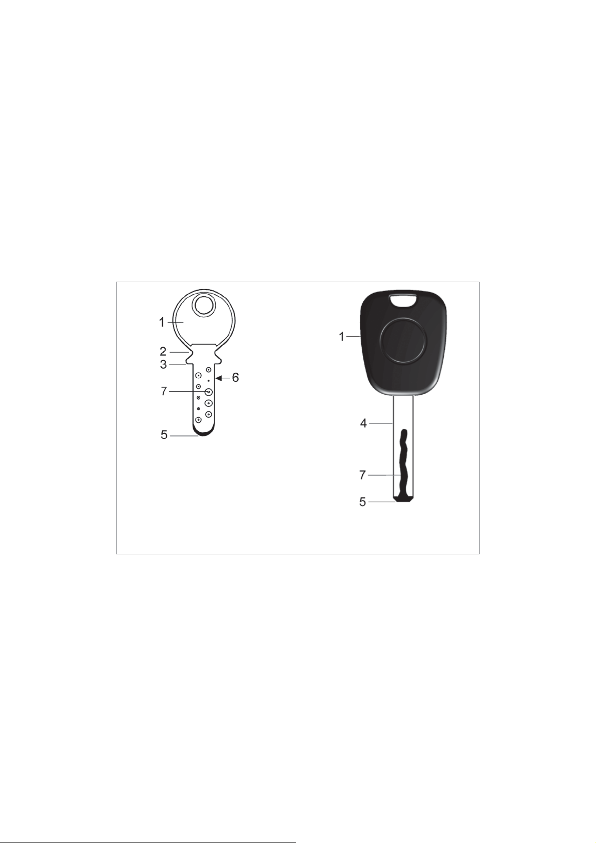
Technical terms
Common technical terms are used in this manual. To assist those with little experience of key cutting, below is an
illustration of the terms used for the different parts of keys.
DIMPLE KEYS
keys with holes of different dimensions,
depths, positions and shapes
1) Head 5) Tip
2) Rim 6) Edge
3) Shoulder Stop 7) Cuts
4) Stem
Copyright Silca S.p.A. 2017
LASER (SIDEWINDER) TYPE KEY
LASER is the name given to the
special sidewinder milled keys
Fig. 1
1

Operating manual - English Twister II
GENERAL INTRODUCTION
The TWISTER II key-cutting machine has been designed according to CE specifi cations. From the design stage
risks for the operator have been eliminated in all areas: transport, key- cutting, regulation and maintenance.
Other risks have been eliminated by the use of protective devices for the operator.
The protective devices used are designed not to provoke further risks and, above all, they cannot be ignored
unless deliberately cut out. They do not hinder visibility of the work area.
A special adhesive label is attached to the machine warning the operator to use goggles during the cutting
operations, and this is strongly recommended in this manual.
The material used in the manufacture of this machine and the components employed during use of the machine
are not dangerous and their use complies with standards.
Use
The TWISTER II must be installed and used as specifi ed by the manufacturer.
The TWISTER II key-cutting machine must be used only by skilled personnel (professional use).
The key-cutting machine is designed for use on business or industrial premises (e.g. hardware shops, key cutting
centers, etc...).
If the key-cutting machine is used differently or for purposes different from those described in this manual, the
customer will forego any rights he may have over the Company . Furthermore, unforeseen danger to the operator
or any third parties may arise from incorrect use of the machine.
Negligence in the use of the machine or failure on the part of the operator to observe the instructions given in this
manual are not covered by the guarantee and the manufacturer declines all responsibility in such cases.
IT IS OBLIGATORY to read the manual carefully before using the machine.
Further Risks
There are no further risks arising from the use of the machine.
Protection and safety precautions for the operator
The TWISTER II key-cutting machine is built entirely to CE standards. The operations for which it has been
designed are easily carried out at no risk to the operator.
The adoption of general safety precautions (wearing protective goggles) and observation of the instructions
provided by the manufacturer in this manual eliminate all human error, unless deliberate. The TWISTER II keycutting machine is designed with features which make it completely safe in all of its parts and operation.
• Power supply
The key-cutting machine is powered by electricity supplied through a separate grounded plug.
• Start-up
The machine is turned on by means of the master switch located on the left-hand side. The switch has a safety
function that prevents untimely start-up when voltage returns after a power outage.
• Operation
The machine is started up by means of a motor switch.
• Illumination
The work area is illuminated by a lamp which operates when the machine is switched on with the master switch.
• Maintenance
The operations to regulate, service, repair and clean the machine have been devised in the simplest and safest
way possible. There is no danger of removable parts being re-placed wrongly or unsafely.
2
Copyright Silca S.p.A. 2017
Operating manual - English Twister II
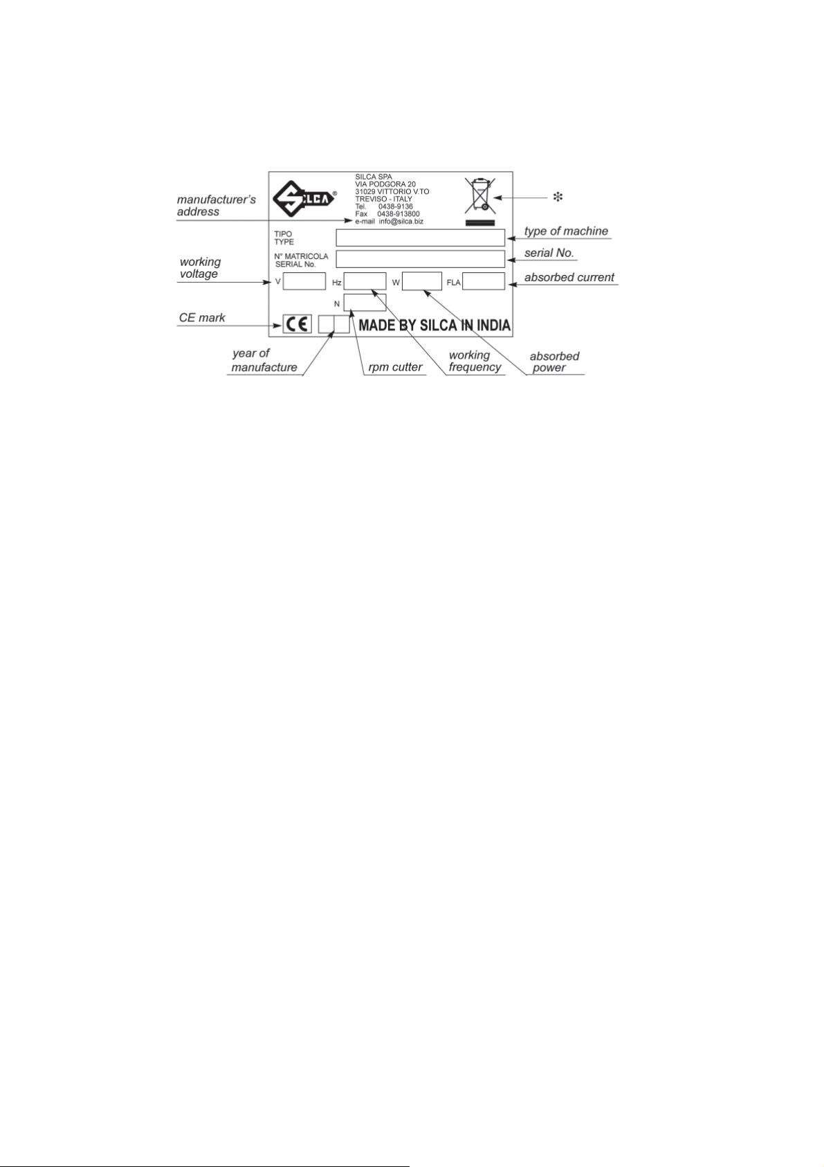
• Machine identifi cation
The TWISTER II key-cutting machine is provided with an identifi cation label which shows the serial number (Fig.
2).
Fig. 2
(*) see chap.9 DISPOSAL.
Copyright Silca S.p.A. 2017
3
Operating manual - English Twister II
1 TRANSPORT
The TWISTER II key-cutting machine is easily transported and is not dangerous to handle. The packed machine
can be carried by two persons.
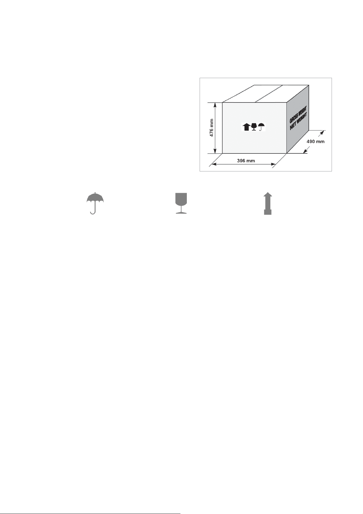
1.1 PACKING
The packing used for the TWISTER II guarantees that the
machine will travel safely without danger of damage to it or
its components.
The packing comprises two shells, lower and upper in
expanded plastic in the machine is wrapped.
A strong outer cardboard box, the measurements of which
can be seen in Fig. 3 and the plastic wrapping protect the
machine even over a long period of storage.
Note: keep the packing and use it every time the machine
must be transported.
Keep dry Handle with care Up
Fig. 3
1.2 TRANSPORT
Symbols are printed on the outside of the cardboard box to give instructions and warnings for transportation.
Use of the packing box whenever the machine is transported will avoid knocks or bumps which could cause
damage.
1.3 UNPACKING
To remove the machine from the packing box:
1) Cut the straps with scissors and remove.
2) Open the box without damaging it so that it may be used again (e.g. shipping to the manufacturer for repairs or
servicing).
3) Check the contents of the box, which should comprise:
1 TWISTER II key-cutting machine packed in a protective shell.
1 set of documents, including: operating manual, spare parts list and guarantee.
1 accessory container.
1 separate grounded plug wire.
4) Remove the key-cutting machine from the protective shell.
1.4 HANDLING THE MACHINE
When the TWISTER II has been unpacked, place it directly on its workbench. This operation can be carried out
by one person.
ATTENTION: hold the base, and no other part, to lift and carry the machine.
1.5 SAFETY
• Protective shield
A special transparent plastic shield prevents chippings from fl ying into the air.
4
Copyright Silca S.p.A. 2017
 Loading...