

Page 1
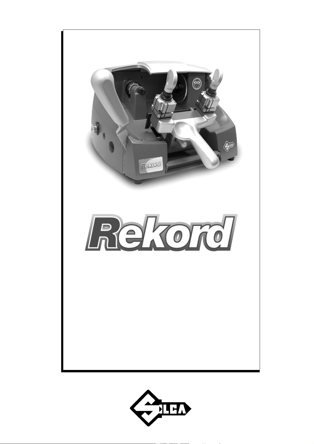
Operating manual
D433453XA
vers.
4.0
®
Page 2

© 2007 SILCA S.p.A - Vittorio Veneto
This manual has been drawn up by SILCA S.p.A.
All rights reserved. No part of this publication may be reproduced or used
microfilm or other) without the written permission of SILCA S.p.A.
Edition: september 2009
Printed in Vittorio Veneto
by SILCA S.p.A.
via Podgora, 20 (Z.I.)
31029 VITTORIO VENETO (TV) - Italy
IMPORTANT NOTE: i
trade-marks or trade names mentioned in our documentation are the exclusive property of authorized
manufacturers of locks and users.
Said trade-marks or trade names are nominated only for the purposes of information so that any lock for which our
keys are made can be rapidly identified.
n compliance with curren
t regulations relating to industrial property, we hereby state that the
in any form or by any means (photocopying,
Page 3

INDEX
1 TRASPORT .....................................................................................................5
1.1 Packing .................................................................................................5
1.2 Transport . .............................................................................................5
1.3 Unpacking .............................................................................................5
1.4 Handling the machine ...........................................................................5
2 WORKING PART ...................................................................................... ... ...6
3 MACHINE DESCRIPTION ...............................................................................7
3.1 Technical Data ......................................................................................8
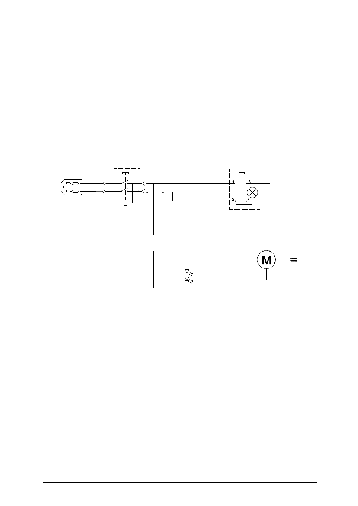
3.2 Electric circuit .......................................................................................9
4 ACCESSORIES PROVIDED .........................................................................10
5 MACHINE INSTALLATION and PREPARATION ........................................11
5.1 Checking for damage .........................................................................11
5.2 Environmental conditions ...................................................................11
5.3 Positioning .. ........................................................................................11
5.4 Removing the blocks ..........................................................................12
5.5 Separate parts ....................................................................................12
5.6 Connection to the mains .....................................................................12
5.7 Description of work station .................................................................13
5.8 Graphics .. ...........................................................................................13
6 MACHINE REGULATION AND UTILIZATION .............................................14
6.1 Checking and setting ..........................................................................14
6.2 Calibration .. ........................................................................................14
7 KEY CUTTING ...............................................................................................16
7.1 Key cutting ..........................................................................................16
8 MAINTENANCE ............................................................................................20
8.1 Replacing the cutting tool ...................................................................20
8.2 Replacing the brush ............................................................................21
8.3 Replacing and/or tightening the belt ...................................................21
8.4 Replacing the tracer point ...................................................................22
8.5 Regulating carriage depth ..................................................................23
8.6 Replacing the fuses ............................................................................23
8.7 Access to the lower part ......................................................................24
8.8 Replacing main switch.........................................................................24
8.9 Replacing motor/condenser.................................................................25
8.10 Replacing lamp feed (transformer) .....................................................26
8.11 Replacing lamp set/lamp protection ....................................................26
8.12 Replacing motor start switch ...............................................................27
9 DISPOSING OF MACHINE............................................................................ 2 8
10 ASSISTANCE ................................................................................................29
10.1 How to request service .......................................................................29
Page 4

Page 5
Operating manual - English REKORD
1
1
1
1
3
3
3
3
7
7
8
2
2
2
5
5
5
5
4
4
6
6
only for
SOFERversion
only for
BRAZIL version
1
8
3
5
GUIDE TO THE MANUAL
This manual has been produced to serve a s a guide for users of the REKORD key-cutting machine.
Read it carefully; it is essential if you wish to operate your machine safely and efficiently.
Consultation
The contents of the manual are divided into sections relating to:
- Transport and handling ................................................................................................... Ch.1
- Description of machine and safety devices
.............................
- Proper use of machine .................................................................................................... Ch.6-7
- Maintenance ....................................................................................................................
Technical terms
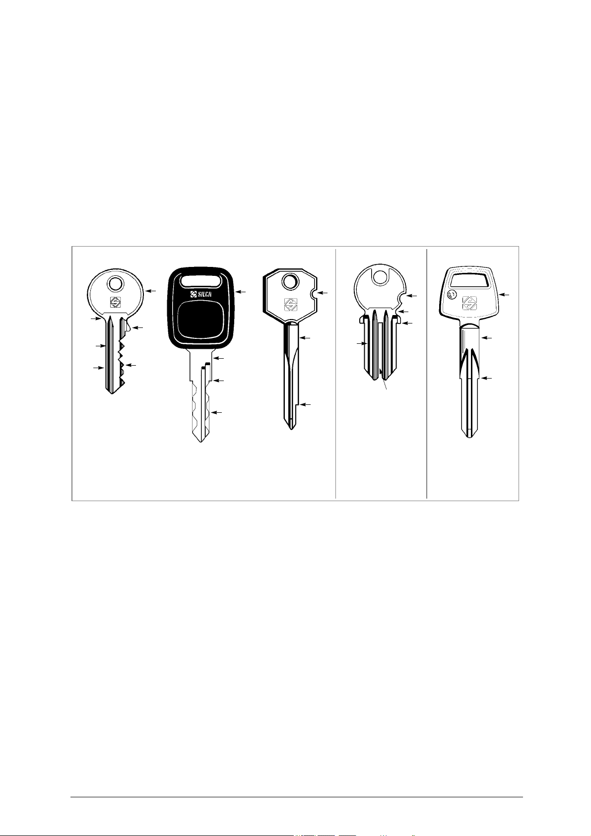
Common technical terms are used in this manual. To assist those with little experience of key cutting,
below is an illustration of the terms used for the different parts of keys:
....................................... Ch.2-3-4-5
Ch.8
Fig. 1
1) Head
2) Rim
3) Stop
4) Stem
5) Tip
6) Back
7) Cuts
8) Stem
Copyright Silca 2 007 3
Page 6

REKORD Operating manual - English
GENERAL INTRODUCTIONS
The REKORD key-cutting machine has been designed according to the specifications of the Machine
Directives. From the design stage risks for the operator have been eliminated in all areas: transport, keycutting, regulation and maintenance.
Other risks have been eliminated by the use of protective
The protecti
ignored unless deliberately cut out. They do not hinder visibility of the work area.
A special adhesive label is attached to th e machi
cutting operations, and this is strongly recommended in this manual.
The material used in the manufacture of this machine and the components emp
machine are not dangerous and their use complies with standards.
ve devices used are designed not to provoke further risks and, above all, they cannot be
Use
The REKORD must be installed and used in the way laid down by the manufacturer.
If th e key-cuttin g ma chine is used differently or for purposes differ ent from those describe d in this
manual, the customer w
danger to the operator or any third parties may arise from incorrect use of the machine.
Negligence in the use of the machine or failure on the
given in this manual are not covered by the guarantee and the manufacturer declines all responsibility
in such cases.
It is therefore indispensable to read the operating manual carefully i
of the REKORD and benefit from its potential.
ill forego any rights he may have over SILCA S.p.A. Furthermore, unforeseen
Instructions manual
The instructions manual provided with the machine is essential to its proper use and to carry out the
necessary maintenance.
We therefore recommend protecting the manual from damage in a safe sheltered place, easily to hand
for quick consultation.
devices for the operator.
ne warning the operator to u
part of the operator to
n order to make the best us
se goggles during the
loyed during use of the
observe the instructions
e
Further Risks
There are no further risks arising from the use of the machine.
Protection and safety precautions for the operator
The REKORD key-cutting machine is built entirely to standards. The operations for which it has been
designed are easily carried out at no risk to the operator.
The a doption o f g eneral safety precautions (wearing pro tective gog gles) an d observatio n of the
instructions provided by the manufacturer in this manual eliminate all human error, unless deliberate.
The REKORD key-cutting machine is designed with features which make it completely safe in all its
parts.
Power supply
•
The key-cutting machine is powered by electricity supplied through a separable earthed plug.
Start-up
•
The machine is started up:
- Activating the safety main switch on the right-han
- Activating
• Maintenance
The operations to regulate, service, repair and clean the mach
safest way possible. There is no danger of removable parts being re-placed wrongly or unsafely.
• Machine Identification
The REKOR D key-cutting machine is provi ded w ith an iden tification la
number (fig. 2).
the motor on switch the le
ft-hand side.
d side of the machine.
ine have been devised in the simplest and
bel w hich show s the seria l
Fig. 2
4 Copyright Silca 2 007
(*) see chap. 9 "DISPOSING OF MACHINE", page 28.
Page 7
Operating manual - English REKORD
490
540
380
Keep dry This side up
Handle with care
1 TRANSPORT
The REKOR D key-cutting machin e is easily transpor ted an d is not da ngerous to ha ndle. The packed
machine can be carried by one person.
1.1
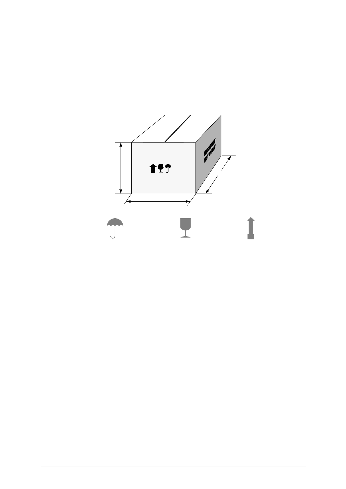
Packing
The REKORD is packed in a strong cardboard box, the dimensions of which are shown in fig. 3, sufficiently
robust to be used for storing the machine for long periods.
Inside the box the machine is enclosed in two expanded polymer shells. The shells and cardboard box
ensure safe transportation and protect the machine and all its parts.
Fig. 3
1.2
1.3
1.4
Transport
To avoid damaging th e R EKORD it must alw ays be tr ansported in its packin g case. This will prevent
sudden movements or rough handling from damaging the machine, persons or things.
Unpacking
To remove the machine from the packing box:
1) cut the straps with scissors and remove.
2) prise off the staples.
3) open the box without damaging it as it may be used again (e.g. removal
for repairs or servicing).
4) check the contents of the box, which should comprise:
- 1 REKOR
- 1 set of documents, including: operatin
- 1 connecting wi
- 1 carriage lever handle;
- 1 tool kit.
5) remove the key-cutting machine from the protective shell.
D key-cutting machine packed in a protective shell.
g manual, spare parts list and guarantee.
re.
s, dispatch to the manufacturers
Handling the machine
When the REKORD has been unpacked, place it directly on its workbench.
This operation can be carried out by one person, firmly holdin
the machine.
g the base, and no other part, to lift and carry
Copyright Silca 2 007 5
Page 8
REKORD Operating manual - English
B CA C1
D
E
G
F L M
O
P
R
S
H1
w
UV
I
J
K
N
H
Q
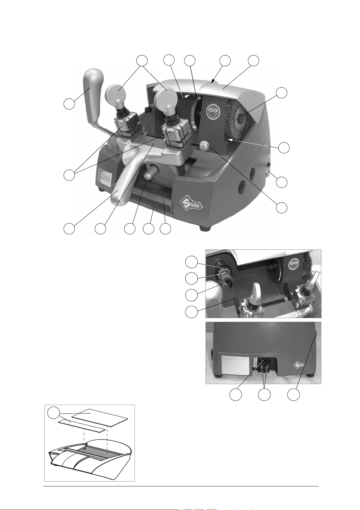
2 WORKING PARTS
Fig. 4
A-carriage lever handle
B-carriage release lever
C-chippings tray
C1 - tool tray
D-carriage movement lever
E-clamps
F-clamp knobs
G - gauge knobs
H-gauge tabs
H1 - lamp
I - tracer point
J-tracer point locking grub screw
centesimal ring
K L - cutting tool
M - top cover
motor on switch
NO - main switch
P-brush
Q - protective pad
R-clamp carriage
S - motor
U - fuses
V-supply socket
W - protective belt cover
6 Copyright Silca 2 007
Page 9

Operating manual - English REKORD
3 MACHINE DESCRIPTION
REKORD is a professional cutting machine for flat keys used with cylinder, car locks and cruciform keys.
The main parts of the machine are described below:
Main switch
The ke y-cutting machine is co nnected to a power supply so cket provided wit h a differentia l switch.
Pressing the switch (O) pow ers the machine a nd illuminates th e wa rning light (H1) to indicate that
current is on.
ATTENTION: Switch (O) is electromagnetic, in the event of a power failure it goes out
automatically. Wh
Motor on switch
The motor on switch (N) is placed on the left-hand side of the REKORD key-cutting machine.
ATTENTION: the i lluminated switch remains on to indicate that the key-cutting machine has been sta
(cutter in motion).
Motor and transmission unit
The motor has belt transmission. The transmission unit is placed on the left of the motor and activates
the brush (P) and cutting tool (L). These components are protected by two covers:
protective
top cover (M)
-
Clamp carriage
The clamp carriage (R) consisting of two clamps, is fitted to the horizontal movement carriage, controlled
by lever (D) and is provided with a handle (A) under which can be found the carriage release button (B).
The carriage movement by means of gears, allows high precision movements which greatly facilitate all
cutting operations.
The carriage is fully protected by
chippings from the work process.
The machine is designed with a ramp along which chippings can fall into the special chippings tray (C),
placed under the carriage and easily removable for emptying and cleaning.
en electricity is restored it must be reset manually to power the machine again.
belt cover (W),
.
a special pan el designed to
prevent the accumula tion of dust an d
rted
Cutting unit
The cutting unit contains the actual working parts of the REKORD key-cutting machine, which operate
together to cut and finish keys "read" from the originals.
The working parts are described below:
Brush
•
ush (P) is used to eliminate burrs from the cuts and is made of non-abrasive materia
The br
Cutting Tool
•
The cutting to
super rapid steel and is protected by a special cover (M) to ensure safe operation.
Tracer point
•
The tracer poi
of the machine base. A centesimal ring (K) ensures regulation of the depth.
Clam
•
The clamps (E) have four sides which
profile (fig. 13-B).
Clamp knobs
•
The clamps a re locked by two anatomical knobs (F) which ensure perfect grip on the keys with only
slight locking pressure.
Calibration tabs
•
The
clamps have two gauge tabs (H) with which to adjust key alignment.
ol (L) is the part of the REKOR D used for cutting key blanks. The cutting tool is in H SS
nt (I), used for reading the profile of the ke
ps
rotate to allow the key to be perfectly secured on its b
y to be copied, is housed
on the left-hand side
l.
ack or in
Copyright Silca 2 007 7
Page 10

REKORD Operating manual - English
3.1
Technical Data
ELECTRICAL PROPERTIES:
- 230V - 50/60Hz 370W 2A
- 120V - 60Hz 560W 4,6A
CUTTING TOOL: HSS Super Rapid Steel
MOTOR: One-speed single phase
- 230V - 50/60Hz; 1350/1620 rpm 0,18 Kw
- 120V-60Hz; 1620 rpm 0,18 Kw
MOVEMENTS: by gear on rectified carriage
CLAMP: rotating with four sides, high precision
MAXIMUM LENGTH OF CUTS: 43 mm (carriage run)
DIMENSIONS: width: 330mm (with max. lever encumbra
SONOROUS PRESSURE: Leq. = 82.5 dB (brass keys)
SONOROUS PRESSURE: Leq. = 87.5 dB (iron keys)
Note: the equivalent sonorous pressure for the iron keys during the normal use (around 5
it is inferior to 85 dB.
WEIGHT: 19 kg.
nce 510mm) depth:
430mm height: 270mm
0 keys a day)
8 Copyright Silca 2 007
Page 11
Operating manual - English REKORD
black
red
Feeder (lamp)
6 LED circuit board
brown
light bluelight blue
brown
yellow/green
1
23
6
4
7
5
()
()
(lamp)
3.2
Electric circuit
The REKORD key-cutting machine is provided with a single phase one-speed motor;
1350 rpm, consumes approx
-
- 1620
- 1620 rpm,
rpm, consumes approximately 0.18 Kw, absorption 2A
consumes approximately
The main parts of the electric circuit on the REKORD are listed below:
1)
Main plug with fuses
2) Safety main switch
3) Illuminated switch
4) Motor: 230V a.c. 50/60Hz
5) Condenser
6) Feeder
7) 6 LED circuit board (lamp)
imately 0.18 Kw, absorption 2A
0.18 kw,
absorption
- (120V a.c. 60Hz)
(230V-50Hz)
(230V-60Hz)
4,6A (120V-60Hz)
Copyright Silca 2 007 9
Page 12
REKORD Operating manual - English
C1
ADHESIVE LABEL
“DANGEROUS MOBILE PARTS”
STEEL PIN Ø 1,20
2 pcs
STEEL PIN Ø 1,70
2 pcs
STEEL BAR
2 pcs
5X20 FUSES (2 pcs)
4 Amps rapid (230V)
8 Amps rapid (120V)
2,5 mm ALLEN KEY
3 mm ALLEN KEY
19 mm SPANNER
10 mm SPANNER
CUTTING TOOL
UNCLAMPING PIN
ADJUSTING BAR
2 pcs
4 mm ALLEN KEY
5 mm ALLEN KEY
ATTENTION
DANGEROUS
MOBILE PARTS
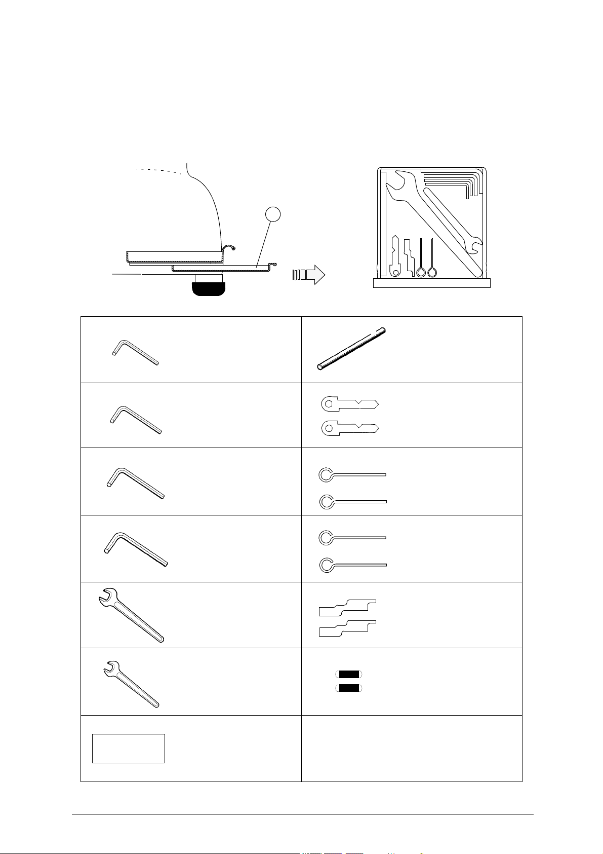
4 ACCESSORIES PROVIDED
To ensure trouble-free working with the REKORD, it is advisable to always have certain spare parts on
hand. It is advisable to always have a tool box containing: tools, cutting tools, brushes, belts and small
replacement parts.
REKORD is supplied with a full range of accessories.
Fig. 5
The accessories provided by Si lca are all that is ne cessary to ca
machine is designed.
rry out the operations fo
r which the
10 Copyright Silca 2 007
Page 13
Operating manual - English REKORD
5 MACHINE INSTALLATION AND PREPARATION
The REKORD key-cutting machine can be installed by the purchaser and does not require any special
skills.
However, some checks and preparation for use need to be carried out by the operator.
5.1
5.2
5.3
ATTENTION:
Checking for damage
The REKORD key-cutting ma chine is solid and compact an d w ill not normally damage if transport,
unpacking and installation have all been carried out according to the instructions in this manual.
However, it is always advisable to check that the machine has not suffered any damage.
Environmental conditions
To ensure that the best use is made of the REKORD key-cutting machine, certain parameters must be
borne in mind:
damp, bad
The id
-
te
-
relative humidity: approx. 60%
-
ly ventilated sites should be avoided.
eal conditions for the machine are
mperat
ure:
from 0 to 40°C
:
Positioning
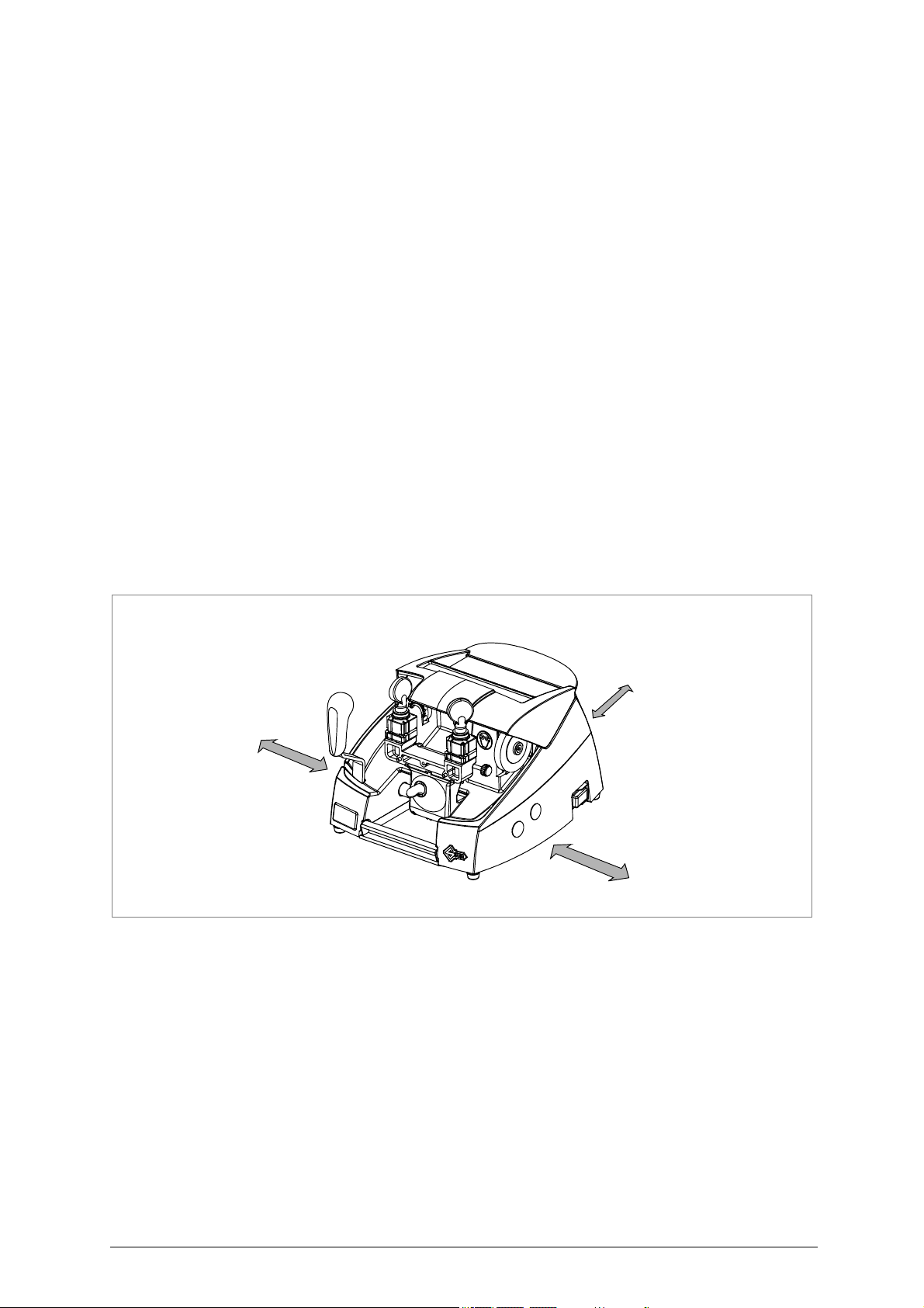
Place the key-cutting machine on a horizontal surface, solid enough to take the weight (19 Kg).
To facilitate operation and maintenance, install the machine with a space of at least 200 mm on all
(fig. 6).
Ensure that the machine stands pe rfectly balanced on the four fee t. Vibration is avoided wh en th e
machine is properly set on the horizontal plane.
ensure that the machine voltage is
earthed and provided with a differential switch.
the same as that of the mains, which must be properly
sides
Fig. 6
200 mm
200 mm
200 mm
Copyright Silca 2 007 11
Page 14
REKORD Operating manual - English
electricity
supply
power
cable
5.4
Fig. 7
5.5
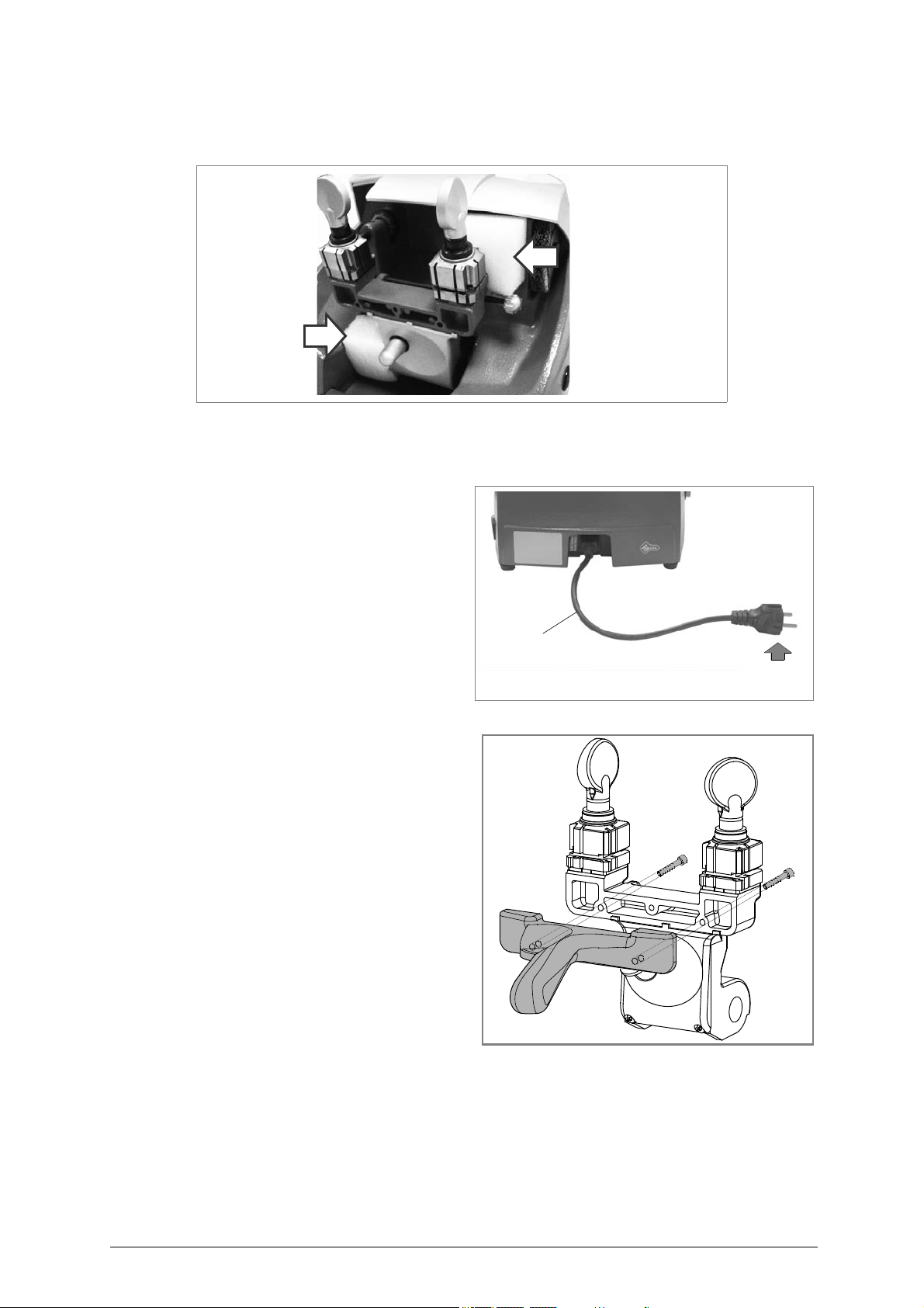
Removing the blocks
Remove the 2 blocks: on the carriage movement and between cutter and jaw (fig. 7).
Separate parts
The separately pa cked pa rts must b e
installed on th e REKORD ke y-cutting
machine by the purchaser,
Connection wire
Connect the key-cutting machine p ower
cable to the electricity mains (fig. 8).
as follows:
5.6
Fig. 8
Carriage lever handle
Screw the carriage handle as shown in fig. 9.
Fig. 9
Connection to the mains
For the safety of the operator and the machine it is important to ensure that the machine is connected
to the proper mains voltage by means of an earthed differential switch.
12 Copyright Silca 2 007
Page 15
Operating manual - English REKORD
ABD
N
G
THE USE OF
PROTECTIVE GOGGLES
IS COMPULSORY
ATTENTION
DANGEROUS
MOBILE PARTS
Place the adhesive label “Dangerous
mobile parts” (ch .4, p age 10 ) as
shown.
5.7
Description of work station
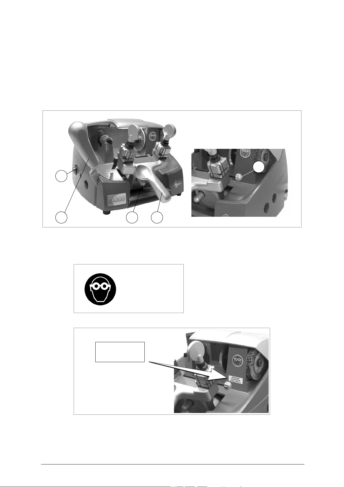
The key-cutting machine needs only one operator, who has the following controls at his/her disposal:
- Switch on the lamp by activating the main switch (O) located on the right-hand side of the machine.
- The motor on switch (N), located on the left-hand side of the machine has a warning light to show
that the key-cutting machine is live.
Ca
rriage movement lever (D)
-
handle lever (A)
rriage
Ca
-
rriage
Ca
Gaug
-
release lever (B)
e knob (G).
Fig. 10
5.8 Graphics
Copyright Silca 2 007 13
Page 16
REKORD Operating manual - English
6
4
8
9
0
cutting
I II III IV V VI
cutting
space
depth
B
A
6 MACHINE REGULATION AND UTILIZATION
6.1
6.2
Checking and setting
The cutting tool on the REKOR D is the part used to cut the ke y blanks and sho uld be period ically
checked and replaced, if necessary.
Every time the cutting tool is changed, and during periodical operational tests, check calibration.
Calibration
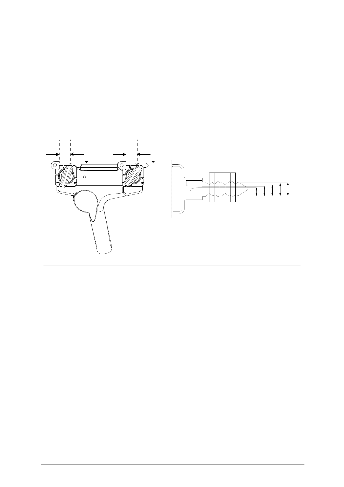
The REKORD key-cutting machine requires two types of calibration: axis and depth.
Axis calibration:
Axis calibration is regulation of the space between the stop and the cuts (fig. 11).
The axis setting for the REKORD is fixed and is established on assembly in our workshops
Fig. 11
Depth calibration:
Depth calibration is regulation of the cutting depth (fig. 11-A).
Proceed as follows:
Ensu
1)
2)
3)
4)
5) Release the carriage by raising the release lever
6)
7)
8)
9)
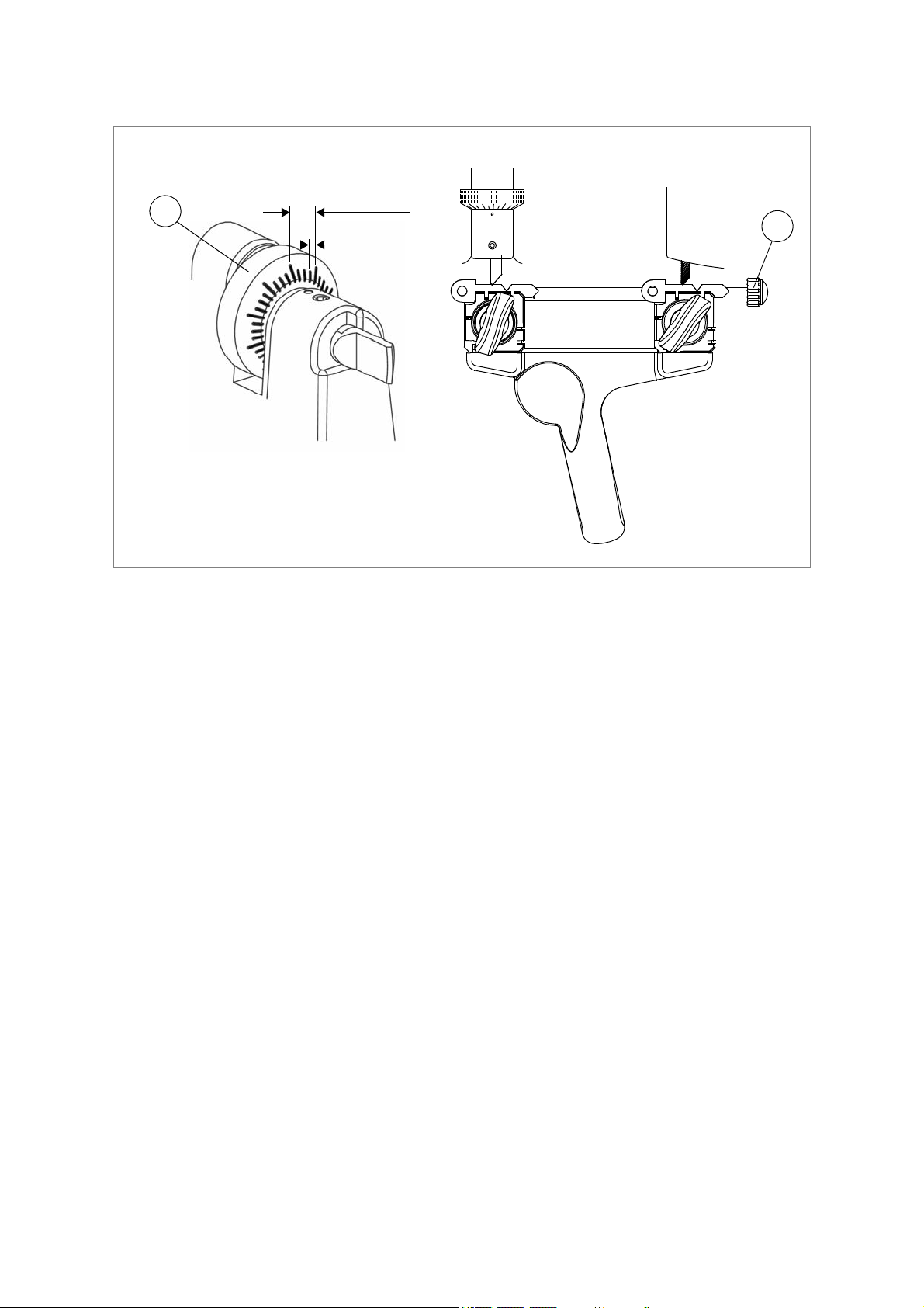
ATTENTION: each notch on the centesimal ring corresponds to 0,025 mm (fig. 12-A).
10)
re that the key-cutting
Place the adju
eck that the adjusting keys adhere properl
Ch
Turn the
keys (fig. 12-B). Lower the gauge rod (G).
ise the
Ra
Take the keys into contact with the cutting too
Turn the
places.
If necessary, regul
a)
b)
c)
Repeat these operations until regulation is complete, then tighten the tracer point locking grub scre
(J).
sting keys (provided) on
gauge rod (G) to
carriage and take up to the cutti
cutting
loosen the screw holding the tracer point (J).
turn the grub screw (K) clockwise to advance the tracer point.
turn the grub screw (K) anticlockwise to return.
tool anticlockwise manually and
ate the depth of
machine is off by unplugging the power cable.
the clamps (fig. 12-B).
y to the clamps (fig. 12-B).
wards the ope
rator so that the gauges come into contact with the adjusting
(B) (fig. 4).
ng tool.
l and tracer point.
check that it skims the adjusting keys in several
the cut with the micrometric tracer point, as follows:
14 Copyright Silca 2 007
Page 17
Operating manual - English REKORD
0,025 mm
0,1 mm
AB
G
K
Fig. 12
Copyright Silca 2 007 15
Page 18
REKORD Operating manual - English
D
A
B
C
F
H
AB
A
SOFER Version
D
A
B
C
B
F
H
7
ATTENTION:
7.1
KEY CUTTING
for complete safety during the cutting operations, take the following precautions:
- Always work with dry hands.
- Check that the machine is properly earthed.
- Wear protective goggles even if the machine has a protective shield over the cutting tool.
- Start the motor (switch N) only after completing th
keys, etc.).
- Keep hands away from the cutting tool in motion.
Key cutting
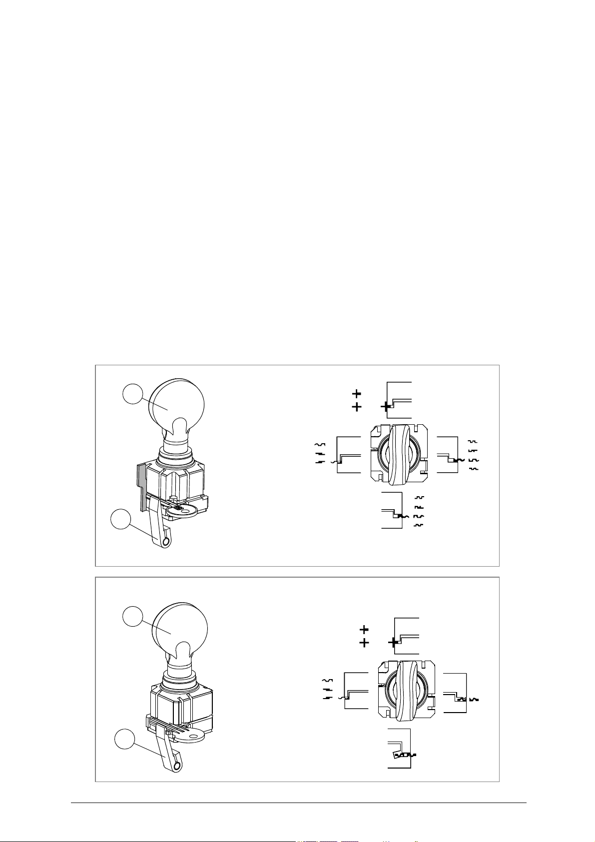
1) Turn the clamps to find the appropriate side for securing the key (fig. -B).
Loosen the knobs (F)
2)
3) Raise the lower part of the clamps and turn to the req
- Side A of the clamp: for keys to be fitted on their backs (fig. -B)
- Side B of the cl
mm (fig. -B))
- Side C and D of the clam
Securing the keys in the jaws
Position the original key (left-hand jaw) and key blank (right-hand jaw), ensuring that:
1)
the keys are p
a)
b) the key stop is resting against the calibration tabs (H);
2) secure the keys by closing the clamps with the knobs (F).
by a couple of turns (fig. -A).
amp: fo
r keys placed on their backs and having cuts with a depth of less than 3,9
p: for keys to be cut on both sides and locked on the groove (fig. -B)
ositioned and secured in the clamp;
ations on the carriage (securing the
e oper
uired position:
Fig. 13
16 Copyright Silca 2 007
Page 19
Operating manual - English REKORD
D
A
B
C
F
H
AB
BRAZIL version
key blank
original key
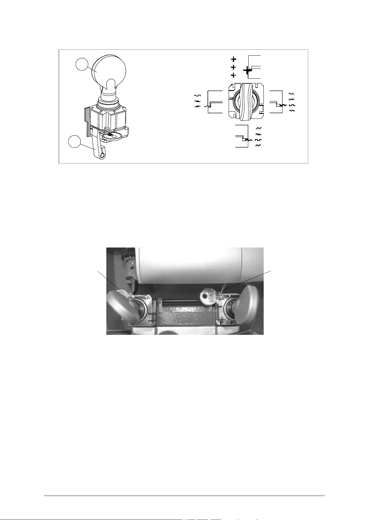
Key cutting
When the R EKORD key-cutting machine has been turned on by means of switch (O) it i s ready for
cutting:
1) Make sure the gauge rod (G) has been lowered.
Take the carriage up to the tracer point and cutting tool
2)
3) To copy the key, move the carriage sideways from right to left by
4) Turn off the machine with main witch (O) before removing the duplicated key.
5) Remove the keys from the clamps.
6) Turn on the machine with switch (O) and smooth off the ke
by releasing the push lever (B).
means of the lever (D).
y edges by means of the brush (P).
Fig. 14
Copyright Silca 2 007 17
Page 20
REKORD Operating manual - English
AB C
pin
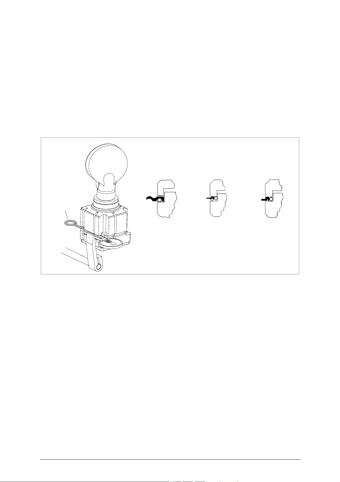
Using the accessories
The accessories provided with the REKORD to assist key-cutting are:
-pins
- bars.
Using the pins
The pins must be inserted between the bottom of the jaw and the back of the key for keys with narrow
stems, and their purpose is to ensure that the key protrudes sufficiently to be cut properly (fig. 15, fig.
15-C).
For keys with narrow, thin stems, two pins must be used (fi g. 15-B), the second one to give a secure
ATTENTION:
grip on the key. If the key thickness is too fine to
used (fig. 15-A).
the pins
with the same diameters for locking both the original and the key blank.
provided have two different diamet
guarantee a good grip in
ers: 1,20 mm and 1,70 mm. It is essential to use pins
the clamps, a pin must be
Fig. 15
18 Copyright Silca 2 007
Page 21
Operating manual - English REKORD
bar
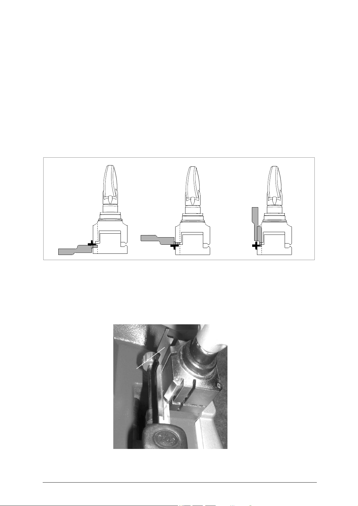
U
sing the bars
The bars provided are used for cutting pin keys and as a tip rest for locking keys with no stop (fig. 16).
Cutting pin keys using bars
The pin keys (90°) can be cut with the REKORD clamps and the aid of the bars.
Positioning pin keys:
1) Leave the gauges in the idle position.
2) Insert the bars with neck into the slot in the clamps.
3) Butt the key stop against the bars (fig. 16).
4) Secure the keys in the clamps.
5) Remove the bars from the clamp grooves
tool.
6) Cut the first side.
7) Repeat the operation, turning the keys in the same direction for the other positions.
to prevent it being touched by the tracer point or cutting
Fig. 16
Tip stop with a bar
The bars can be used with keys which have no stop (fig. 16). Proceed as follows:
1) Leave the gauges in the idle position.
2) Insert the bars into the slot in the clamps.
3) Rest the tip of the key against the bar.
4) Secure the key and remove the bar.
Fig. 17
Copyright Silca 2 007 19
Page 22
REKORD Operating manual - English
locking rod
loosen
tighten
8 MAINTENANCE
ATTENTION: for repairs or replacement of parts for maintenance, the ‘CE’ mark is guaranteed only if original
spare parts provided by the manufacturer are used.
Although the REKORD key-cutting machin e does not r equire special maintenance, it is advisabl e to
check and, if necessary, replace the parts subject to wear, such as: the belt, cutting tool, brush, tracer
point. Replacement is simple and can be carried out by the operator.
CLEANING
Keep the carriage and clamps free of chippings from the cutting operations by cleaning with a dry brush.
ATTENTION:
ATTENTION: to keep the machine well maintained we recommend using protective oil, e.g. WD40 or similar,
do not use compressed air!
applied to the burnished mechanical parts. This prevents oxidation of the parts in question
(clamps, guides, carriages, etc.). Do not contaminate the electronic parts with the oil.
Before starting any type of maintenance (checks or re
never carry out maintenance or servicing with the machine switched on
always remove the mains
follow all the instructions in the
use original spare parts.
always check that an
-
plug.
manual to the letter.
y screws or nu
ts removed when replacing a piece are properly tightened.
placements), read the instructions below:
.
8.1
ATTENTION:
ATTENTION:
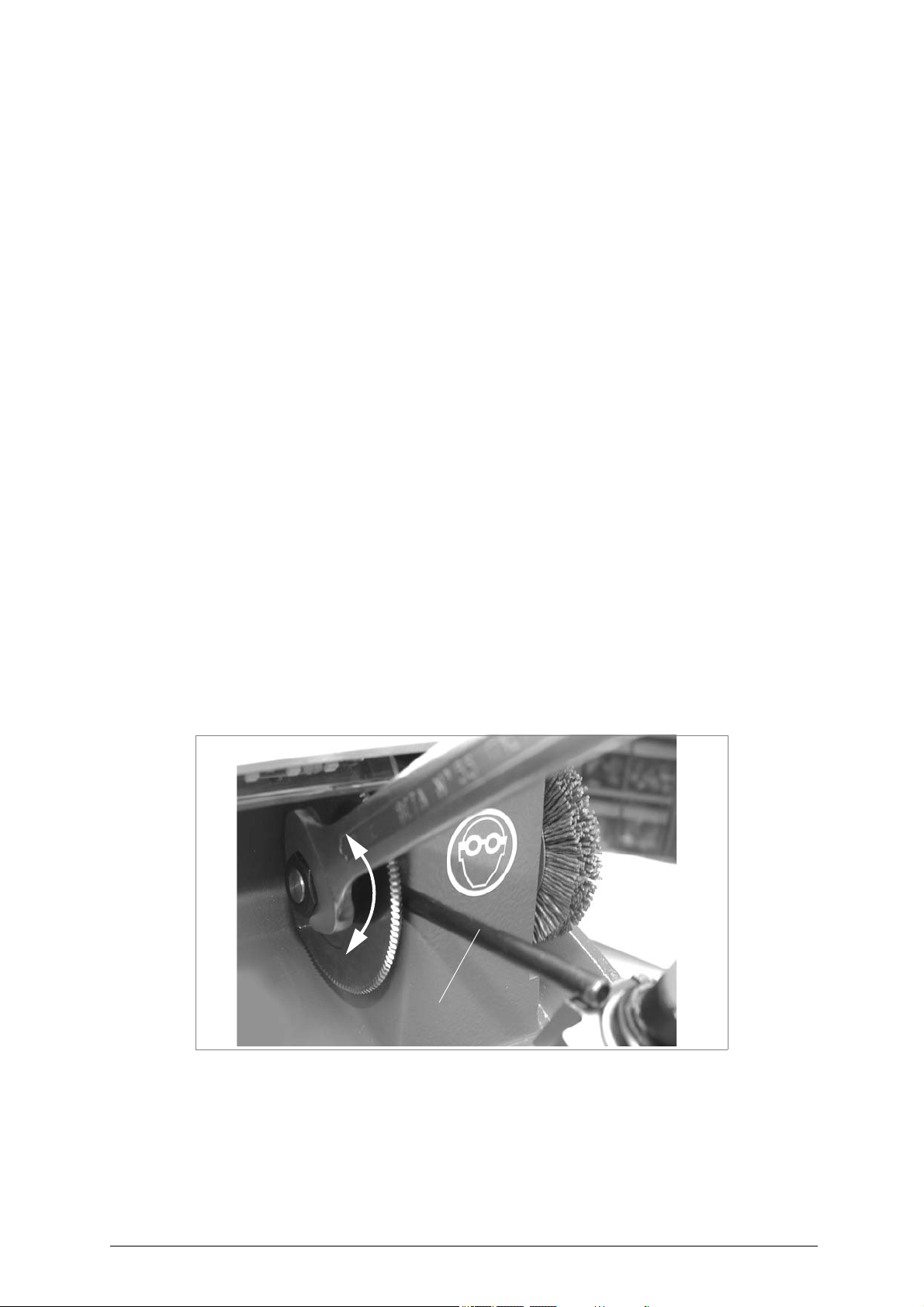
ATTENTION: the tool rotates clockwise.
Replacing the cutting tool
In order to substitute the cutting tool you don’t need to remove the cutting tool cover.
To replace a worn cutting tool, proceed as follows:
remove the mains plug
Slot the locking rod (standard) into
1)
2) Use the spanner provided to loosen the cutting too
the thread is left-handed.
3) Remove the w
4) Carefully clean the new cutting tool and its seat.
5) Install the new cutting tool and tighten the nut.
Re
move the locking pi
6)
.
orn cutting tool.
n.
the hole of the cutting tool shaft (fig. 18).
l locking the nut.
Fig. 18
20 Copyright Silca 2 007
Page 23
Operating manual - English REKORD
locking
brush holding
rod
screw
loosen
tighten
M1
M2
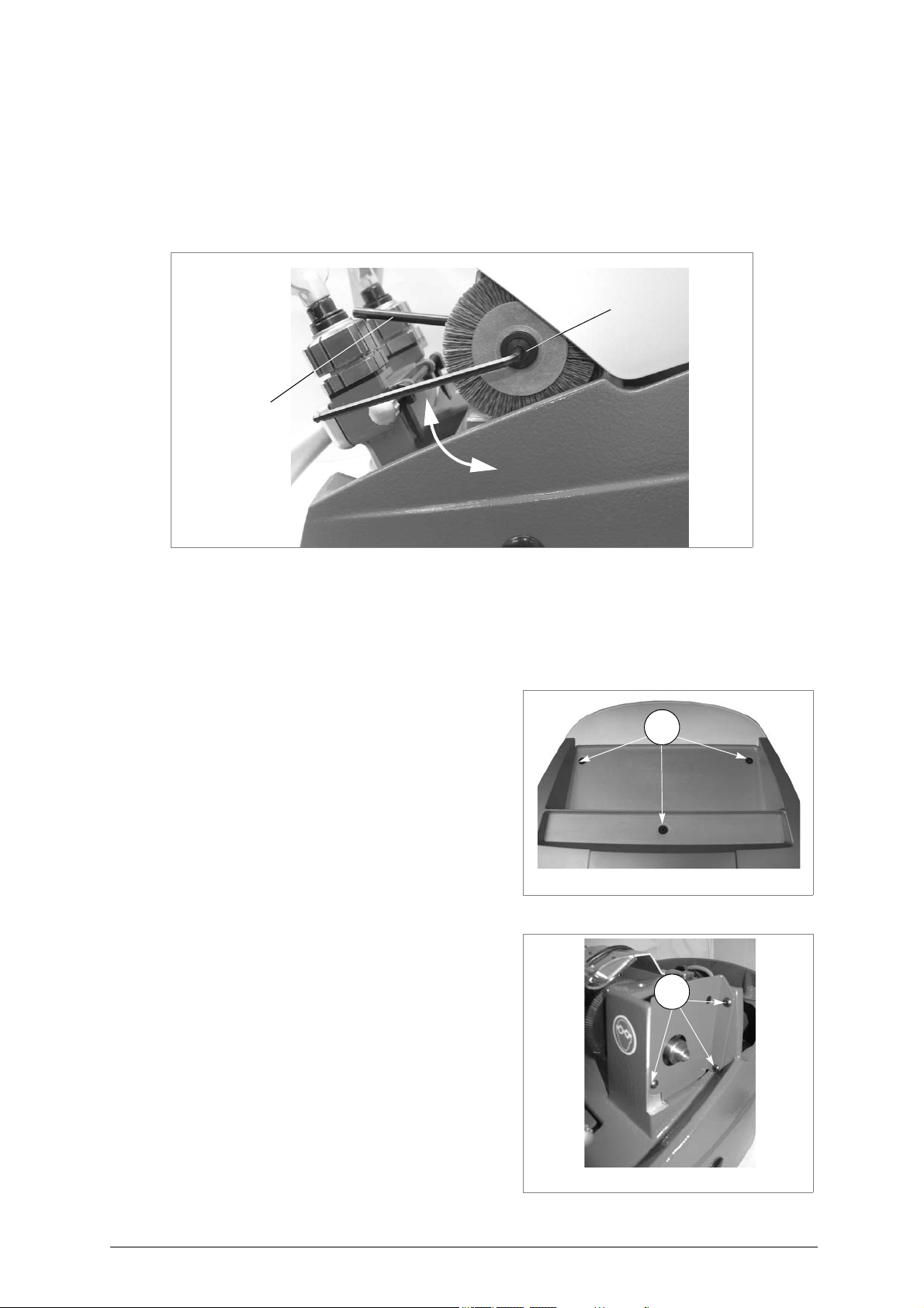
8.2 Replacing the brush
When the brush no longer cleans off the burrs it must be replaced as follows:
ATTENTION:
remove the mains plug
1) Place the locking rod (provid
2)
Use the Allen wrench (provided) to loosen the screw holding the brush in place (fig. 19).
3) Replace the brush and tighten the screw with the Allen wrench.
4) Remove the spanner from the motor shaft.
.
ed) in position on the motor shaft.
Fig. 19
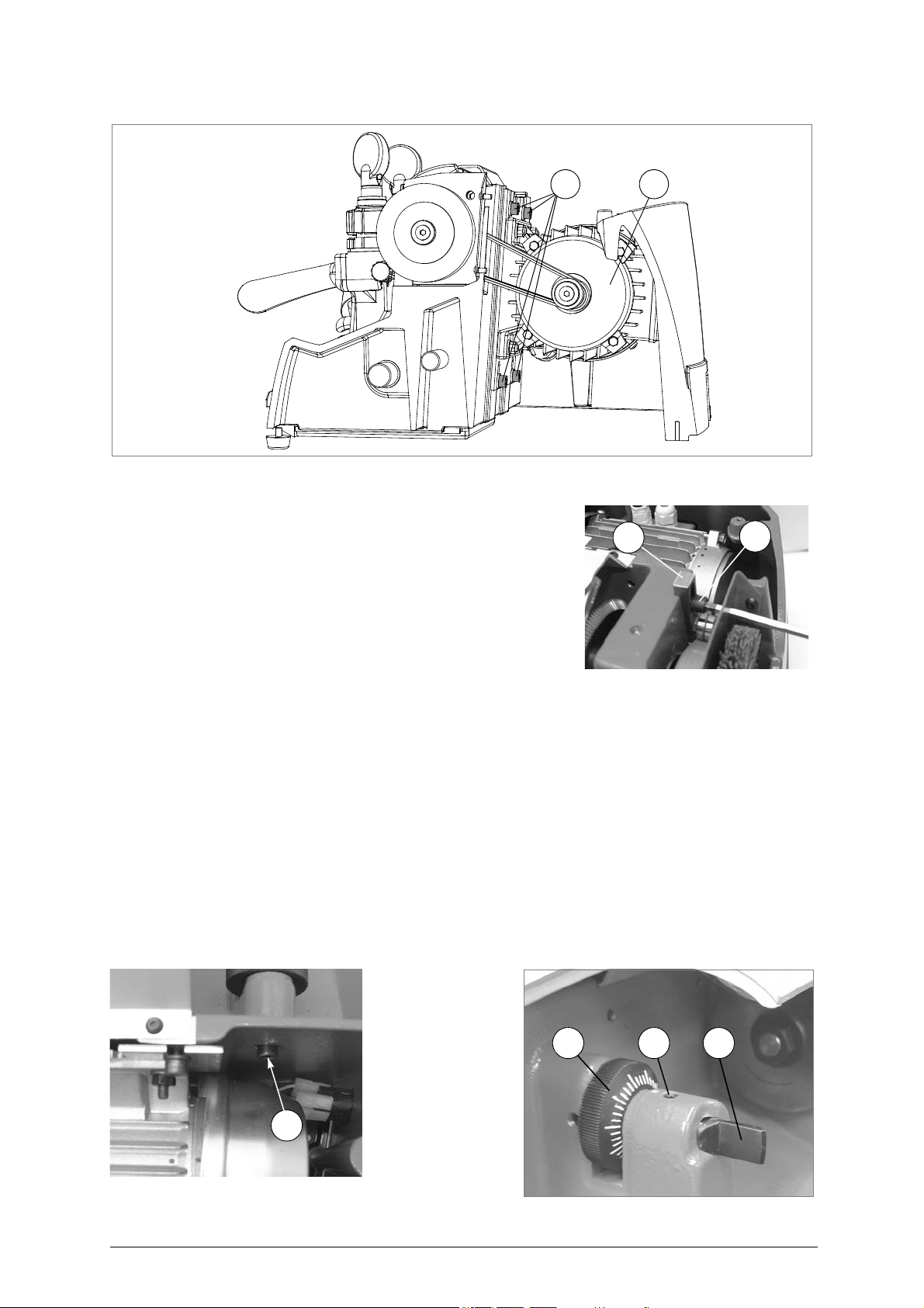
8.3 Replacing and/or tightening the belt
Worn or loose belts (T) must be replaced or adjusted so as to ensure safe and proper operation of the
cutting tool/ brush.
Tension:
ATTENTION: remove the mains plug.
1) Remove the two protective pads (Q) (fig.4, page
6).
2) Loosen the 3 screws (M1) and remove the top
cover (M).
3) Loo
sen the 4 screws (S1) of the plate motor (fig.
22).
4) Push the motor down until the proper belt tension is obtained.
5) Tighten the four screws.
Fig. 20
Replacement:
ATTENTION:
remove the mains plug.
1) Remove the two protective pads (Q).
2) Loosen the 3 screws (M1) and remove the top
cover (M).
3) Remove the brush (fig. 19).
4) Remove the 3 screw (M2) (fig. 19) to remove the
protective cover (fig. 22)
5) Loosen the 4 screws (S1) of the plate motor (fig.
22)
6) Raise the motor and remove the worn belt.
7) Fit the new belt.
8) Replace the motor in its previous position.
9) Tighten the 4 screws.
10) Replace the belt cover
11) Replace the brush
12) Replace the top cover
Fig. 21
Copyright Silca 2 007 21
Page 24
REKORD Operating manual - English
SS1
P2
P1
K1
K J I
Fig. 22
FOR VERSIONS WITH BELT TIGHTENERS (P1) (Fig.23)
- Loosen the screw (P2) and raise the belt tightener in order
to remove the belt.
- Push the belt tightener downwards to tighten the belt.
- Secure the belt tightener with the screw (P2).
FOR VERSIONS WITH BELT TIGHTENERS (P1) (Fig.23)
- Push the belt tightener downwards to tighten the belt.
- Secure the belt tightener with the screw (P2).
8.4 Replacing the tracer point
To replace the tracer point (I) (fig. 25), proceed as follows:
ATTENTION:
remove the mains plug
1) Remove the two prot
2) Loosen the 3 screws (M1) and remove the top cover (M).
3) Loosen the screw (K1).
4) Loosen the grub screw (J).
5) Loosen the tracer point by turning it an
6) Fit the new tracer point and screw down to the end of run.
7) Tighten the grub screw (J).
8) Tighten the screw (K1).
9) Re-set the machine as described in chap. 6, page 14.
.
ective pads (Q).
ticlockwise un
Fig. 23
til is fully released.
Fig. 24
22 Copyright Silca 2 007
Fig. 25
Page 25
Operating manual - English REKORD
allen
wrench
0,1 mm
spanner
fuse box
U
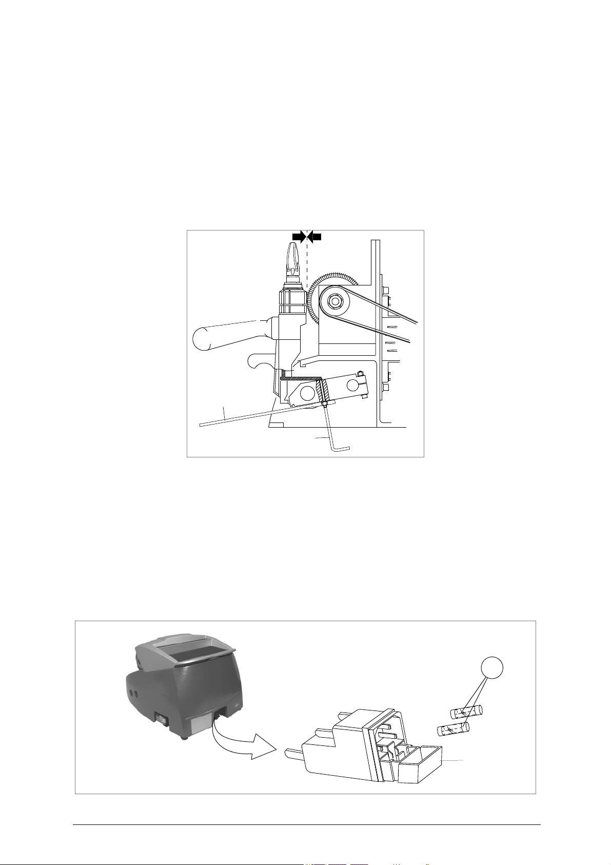
8.5 Regulating carriage depth
The carriage on the REKORD can be regulated to protect the clamps from coming into contact with the
tracer point or cutting tool.
ATTENTION: the play between cutting tool/trac
Should it be different from this
ATTENTION: re
move the mains plug.
1) Release the carriage, raise against the cutting tool and take to the end of its run (fig. 26).
2) Remove the chippings tray (C) and tool holder (C1).
3) Release the nut with the spanner (fig. 26).
4) Use the Allen wrench to screw or unscrew the grub screw in order to move the carriage away from
or towards the tracer point and cutting tool.
5) Tighten the nut.
er point and clamps must be 0.1 mm.
, proceed as follows:
Fig. 26
8.6 Replacing the fuses
ATTENTION: remove the mains plug.
1) Unplug the power cable from the key-cutting machine socket.
2) Turn the key-cutting machine round so as to reach the fuse housing on the back.
3) Remove the fuses box placed below the key-cutting machine socket (V) (fig. 27).
4) Replace the fuses (U) (fig. 27).
5) Close the fuses box and connect the power cable.
ATTENTION: fuses must always be replaced with others of the
Amps for 230V; 8 Amps for 120V.
same type (rapid) and with the
same Amps (4
Fig. 27
Copyright Silca 2 007 23
Page 26
REKORD Operating manual - English
Y
Y1
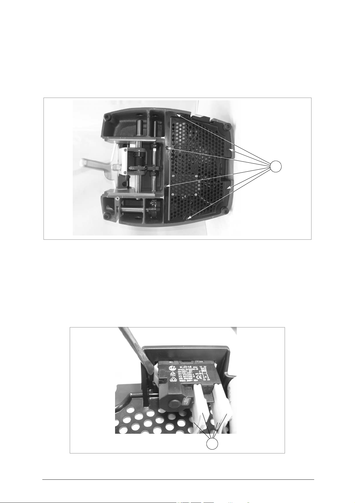
8.7 Access to the lower part
ATTENTION:
remove the mains plug
1) Detach the wire from the key-cutting machine socket.
Remove the double box (tool holder/swarf tray) (C) and (C1).
2)
3) Turn the machine over onto its back.
4) Loosen the 6 screws (Y) to remove the bottom grate.
.
Fig. 28
8.8 Replacing main switch
ATTENTION:
remove the mains plug
1) Access the bottom part (see ch. 8.7).
2) Detach the 4 connectors (Y1) paying special atten
3) Use a screwd
4) Fit the new main sw
5) Reconnect the 4 connectors (Y1).
6) Replace the bottom grate and
7) Turn the machine back into place on the work bench.
.
river to lower the internal tabs fixing the switch, then pull it out.
itch.
tion to their position.
secure with the screws (Y) (fig. 28).
Fig. 29
24 Copyright Silca 2 007
Page 27
Operating manual - English REKORD
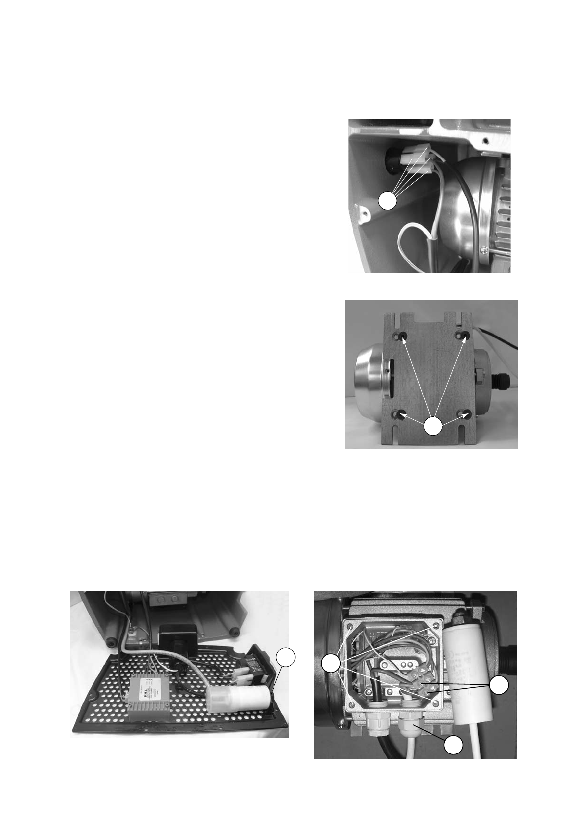
8.9 Replacing motor/condenser
Motor
ATTENTION:
remove the mains plug
1) Remove the two protective pads (Q).
2) Loosen the 3 screws (M1) and remove the top cover
).
(M
3) Detach the 4 co nnectors (S2
switch.
4) Loosen the 4 screws (S1) ( fig. 22 ) on the motor
fixing plate and remove the belt.
5) Loosen completely only the 2 lower screws (S1) the
motor fixing plate and pull downwards.
.
) from the mo tor o n
S2
ATTENTION:
Condenser
Fig. 30
remove the mains plug
- Access the bottom part (see ch. 8.7)
- Remove the motor (see ch. 8.9 - Replacing motor)
- Loosen the nut (Z) (fig. 32) and remove together with
the washer.
- Loosen the 4 screws (S4) on the motor box and remove.
- Loosen the 2 condenser connection screws (X1).
- Loosen the nut on the wire grommet (X) and remove
the conde
- Fit the new conden ser, ta
nut (X) replace the motor box and secure with the 4
screws (X1).
- Tighten the grommet nut (X), rep lace the motor box
and secure with the 4 screws (S4).
eplace the condenser (see points 9 to 13).
- R
- Loosen the 4 screws (S3) on the motor fixing plate.
- Secure the new motor on the fi xing pla te with the
screw (S3).
- Replace the motor.
6) Place the machine in position on the work bench.
7) Install the belt and tighten the 4 screws (S1) (fig. 22) of the plate motor.
8) Connect the 4 connectors (S2) (fig. 30) to the motor on switch and fit the earth wire to its screw with
the nut (S5) (fig. 34).
9) Replace the condenser and secure with washer and nut.
10) Replace the bottom grate and secure with the screws (Y) (fig. 28).
11) Place the machine in position on the work bench.
12) Replace the top cover and secure with the 3 screws (M1).
13) Replace the protective pads (Q).
nser.
.
king the wire through the
S3
Fig. 31
Fig. 32
Z
S4
X1
X
Fig. 33
Copyright Silca 2 007 25
Page 28
REKORD Operating manual - English
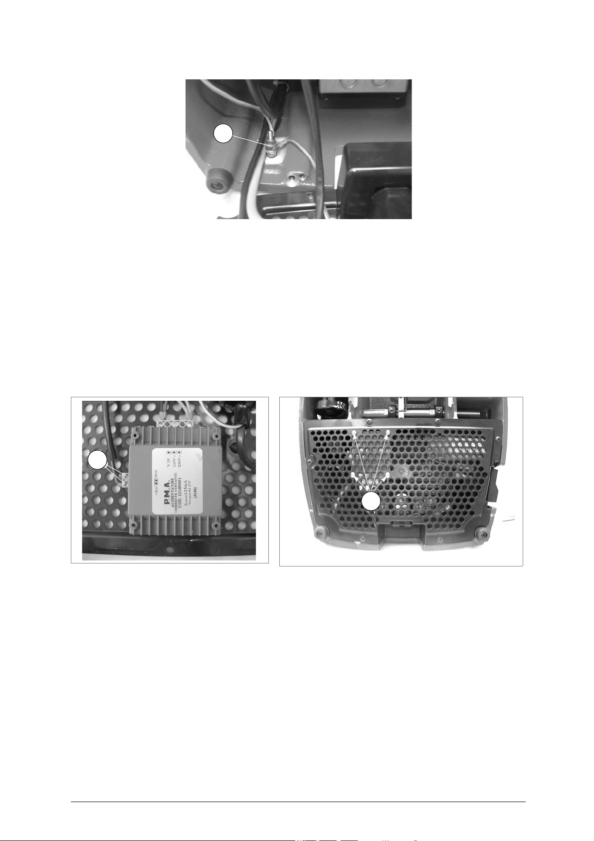
S5
Q1
Q2
Fig. 34
8.10 Replacing lamp feed (transformer)
ATTENTION:
remove the mains plug
1) Access the bottom part (see ch. 8.7).
2) Loosen the 2 low voltage connector screws (Q1) remove and place in their seat on the n
mer, securing with the 2 screws.
3) Loosen the 2 mains connector screws (Q3) remove and place in their seat on the new transformer,
securing with the 2 screws.
4) Loosen the screws (Q2) fixing the transfo
5) Place the new
6) Replace the bottom grate and secure with the screws (Y) (fig.28, page 24).
7) Place the machine in position on the work bench.
.
ew transfor-
rmer to the bottom plate and remove.
transformer in position and secure with the screws (Q2).
Fig. 35
8.11 Replacing lamp set/lamp protection
Lamp set
ATTENTION:
26 Copyright Silca 2 007
remove the mains plug
1) Remove the two protective pads (Q).
2) Loosen the 3 screws (M1) and remove the top cover (M).
3) Access the bottom part (see ch. 8.7).
4) Loosen the 2 low voltage connector screws (Q1) and remove them.
5) Position the machine upright again.
6) Loosen the 2 lamp fixing screws (L1) and remove.
7) Replace the top cover and secure wi
8) Turn the machine over onto its back.
9)
Connect the 2 connectors in the low voltage supply o
10) Replace the bottom grate and secure with the screws (Y) (fig. 28).
11) Place the machine in position on the work bench.
.
th the 3 screws (M1).
utlet seat and secure w
Fig. 36
ith the 2 screws (Q1).
Page 29
Operating manual - English REKORD
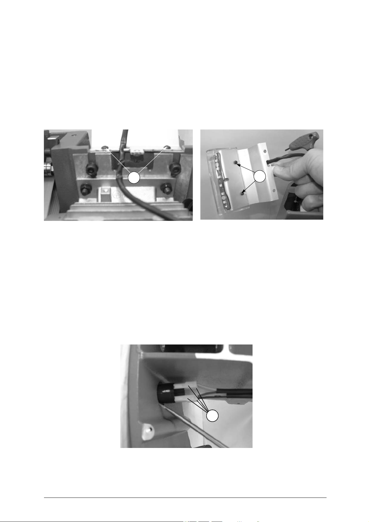
L1
L2
S2
Lamp protection
ATTENTION:
remove the mains plug
1) Remove the two protective pads (Q)
2) Loosen the 3 screws (M1) and remove the top cover (M).
3) Loosen the 2 lamp fixing screws (L1) and remove.
4) Loosen the 2 screws (L2) in order to remove the lamp protection (L3).
5) Fit the new protection and secure with the 2 screws (L2)
6) Replace the lamp unit and secure with the 2 screws (L1) making sure the wiring is positioned towards the bottom of the machine.
7) Replace the top cover and secure wi
.
th the 3 screws (M1).
Fig. 37
8.12 Replacing motor on switch
ATTENTION:
remove the mains plug
1) Access the bottom part (see ch. 8.7).
2) Detach the 4 connectors (S2) (fig. 39) paying specia
3) Use a screwdriver to turn down the internal switch fixing tabs and pull it out.
4) Fit the new switch in its seat and reconnect the 4 con
position.
5) Replace the bottom grate and secure with the screws (Y) (fig. 28).
6) Place the machine upright on the work bench.
.
l attention to their position.
nectors (S2) paying special attention to th
Fig. 38
eir
Fig. 39
Copyright Silca 2 007 27
Page 30

REKORD Operating manual - English
9 DISPOSING OF MACHINE
EU regulations establish special arrangements for the disposal of waste (**).
Waste deriving from cutting operations
Although residue coming from the key-cutting operations is classified as special waste, it is included in
solid urban waste (SUW) as metal wool.
Such waste is sorted according to its classification under current Italian and EU law and consigned to
the proper disposal units.
Cases where waste can be considered contaminated or containing toxic/harmful substances sufficient
to transform it from SUW to toxic/harmful waste, are listed in the enclosures to current Italian and EU
waste disposal regulations.
Re-cycling is a recommended ecological practice.
Packing
The REKORD is consigned in a cardboard packing box which can be re-used if undamaged. When it is
to b e thrown awa y it is cl assified as solid urban waste and should be placed i n the special pa per
collecting bins.
The protective shell containing the ma chine is in polymer, classified as SUW, and can th erefore
placed in an ordinary waste bin.
be
INFORMATION FOR USERS
as per art. 10 of Directive 2002/96/CE of 27/01/2003
regarding waste from electric and electronic appliances (RAEE),
• The symbol illustrated above, also found on the machine, indicates that it has been placed on the market and
must be included in separ ate rubbish collection when t he user wishes to dis pose of it (including all
components, sub-assemblies and consumables that are integrated in the product).
• For informatio n about the collection sys tem for su ch applianc es please c ontact SILCA S.p.A. or another
subject registered in the various National Rolls for other countries in the European Union. Household waste
(or of similar origin) can be included in the separate collection system for urban waste.
• On purchasing a new appliance of equivalent type, the old one can be consigned to the dealer. The dealer
will then contact whoever is responsible for collecting the appliance.
• Suitable separate collection of the unused appliance and its dispatch for treatment, recove ry and
environmentally compatible disposal, makes it possible to avoid potential negative effects on the environment
and human health, and aids recycling and the recovery of the materials used.
• Unauthorised disposal of the product by u sers involves the application of the s anctions provided for in
received Directives 91/156/CE and 91/689/CE
(**) "Waste" is any substance or object deriving from human activity or natural cycles, thrown away or to be thrown
away.
28 Copyright Silca 2 007
Page 31

Operating manual - English REKORD
10 ASSISTANCE
Silca provides full assistance to purchasers of the REKORD key-cutting machine.
To ensure complete safety for the operator, any job not specified in this ma
by the manufacturer or in the special Service Centres recommended by Silca.
On the back cover of th is manual is a list of the manufacturer’s add resses; listed bel ow are the
addresses of specialised Service Centres.
10.1 How to request service
The guarantee attached to R EKORD key-cutti ng machines ensures fre e repai rs or repl acements of
faulty parts within 24 months of purchase. All other service calls must be arranged by the customer with
Silca or with a Silca service centre.
nual should be carried out
Copyright Silca 2 007 29
Page 32
VITTORIO VENETO 24/03/2011
CE DECLARATION OF MACHINE COMPLIANCE
SILCA S.p.A. - VIA PODGORA 20 ( Z.I.)
31029 VITTORIO VENETO (TV) - (ITALY)
TEL. 0438 9136 - FAX. 0438 913800
Declares under its own responsibility that the Key-cutting machine model
REKORD
complies with the requirements of the following European Directives:
European Union DIRECTIVE 2006/42/CE (Machines)
and with the EN 12100-1:2003 / EN 12100-2:2003 Standards
European Union DIRECTIVE 2004/108/CE
and with the EN 55022 : 1998 + A1 : 2000 + A2 : 2003
EN 61000 – 3 – 2 : 2000 + A2 : 2005
EN 61000 - 3 – 3 :1995 + A1 : 2001 Standards
European Union DIRECTIVE 2006/95/CE
and with the EN 60950 – 1 : 2006 Standards
Claudio Tomasella of the Silca S.p.A. Research & Development Division is authorized
to create a Technical File.
General Manager Basic Production Center
(Electromagnetic Compatibility)
(Low Voltage ) | 07 |
Page 33

SERVICE CENTERS - CENTRI DI ASSISTENZA - KUNDENDIENSTZENTREN - CENTRES D’ASSISTANCE
CENTROS DE ASISTENCIA - CENTROS DE ASSISTÊNCIA - BIJSTANDSCENTRA
COUNTRY COMPANY ADDRESS CITY
Algeria
Argentina
Australia
Austria
Belgium
Brazil
Bulgaria
Burkina
Faso
China
Colombia
Croatia
Cyprus
Czech
Republic
Denmark
Egypt
Finland
France
Germany
Greece
Greece
Greece
Greece
Guinea
Holland
Holland
Holland
Hong Kong
Hungary
India
Iran
Israel
Italy
Japan
Sarl Maghreb Clés
Distribuidora
Frappampino S.r.l.
Locksmiths' Supply Co.
Pty Ltd.
Erwe Gmbh Feldgasse, 16 Feldkirchen A-9560 +43-42762816
Duitman Bvba Zinkstraat 13 Halle 1500 +32-2-3831620
Kaba Do Brasil Ltda.
Intesa S.r.l. 1, Kukush Sofia 01309 +359-2-8211425
Diallo Mamoudou
Silca China Xinhua Industrial Zone
Flexon Llaves S.A.
Ferrotechna d.o.o. Japodska, 66c Pula 52100
G.H. Yacoubian Ltd. 74/B, Regaena Street Nicosia +357-22-663525
H&B Plus. s.r.o. Zatecká, 8 Plzen 30148 +420-377-225903
Agenturcentret A.S Brydehusvej 20 Ballerup 2750 +45-70111211
Gam Transworld
Hardware Group Finland
Oy. (Hgf Ltd)
SILCA S.A.S.
SILCA GmbH Siemensstrasse, 33 Velbert 42551 +49-2051-2710
Chrisikos K. Ioannhs 7 Pipsou St. Thessalonik
F. Sotiropoulos & Son
O.E.
GEMKA-Karidis
G. & Sons OE
Fr.lli Raptakis Pili Iisou 10 Iraklion - Crete +30-2810-285000
Soguintec S.A. Calle Abilio Baloboa
Duitman B.V. Aquamarijnstraat 5 7554 NM - Hengelo +31-74-2452520
H. Cillekens & Zn. B.V. Metaalweg, 4 JB Roermond 6045 +31-475-325147
Steenhauer B.V. Oude Raadhuisstraat 1 Ap Leidschendam 2266 +31-70-3177262
Professional Lock Centre
Co. Ltd.
Kaba Elzett Megyeri út 51 Budapest 1044 +36-1-3501011
Minda Silca Engineering
Ltd.
Klidavarshayan Co.
A.M.C.I. Locksmith
Supply Ltd.
SILCA S.p.A. Via Podgora, 20 (Z.I.) Vittorio Veneto - TV 31029 +39-0438-9136
Clover Co. Ltd
Coopérative Ettadhamoune
Local 21/A
La Rioja, 483 Cordoba 5000 +54-351-4216368
140/158 Dryburgh St. North Melbourne
Rua Guilherme Asbahr
Neto 510
Av.Houari Boumedienne
Porte N. 1651
Av.Carrera 70 No.99 - 55
Entrada 1
23 Omer Ibn El-Khatar
Street
Luostarinportti 5 Kirkkonummi 02400 +358-9-2219490
12, Rue de Rouen
B.P.37
Patission Str., 110 Athens 11257 +30-210-8234009
Lykoyrgoy St. 14-16 Athens 10552 +30-210-3243000
Unit A-D, 9/F.
Gemstar Tower,
23 Man Lock Street
Plot No. 37, Toy City Greater Noida 201308
No.73 Stakhr. St - Emam
Khomaini Ave.
22 Efal Street Kiryat Aryeh
P.O.Box 3667
1-2-40 Haradanaka,
Toyonaka-shi
Badjarah / Alger 16209 +213-21-264934
São Paulo
01BP / 2957
Ouagadougou 01
Guanghai County,
Taishan, Canton
Bogotà +571-2538300 +571-5331842
Heliopolis
El Cairo
Z.I. Limay
Porcheville
Malabo - Provincia
del Bioko Norte
Hunghom, Kowloon,
Hong Kong
Tehran +98-216-6702757
Petah Tikva 49130 +972-3-9230331
Osaka
AREA
CODE
VIC
3051
04646-
001
+226-710448
+86-750-5325698
78440 +33-1-30983500
TK
54627
+240-556618
+852-23302268
5610807
PHONE
+61-39-3297222
+55-11-5545-4510
+385-52-503-529
+385-52-502-609
+20-2-22404705
+20-2-26441401
+30-2310-510336
+91-987-397630
+91-987-397631
+81-6-6844-2111
FAX
e-mail
+213-21-264888
+54-351-4229003
+61-39-3281731
+43-42765054
[email protected]
+32-2-3831622
+55-11-5545-4515
+359-2-8211347
+226-710002
+86-750-5315655
+385-52-503-529
+357-22-669009
+420-377-225904
+45-70111221
+20-2-22404705
+358-9-2962186
+33-1-30983501
+49-2051-271172
+30-2310-521651
+30-210-8238480
+30-210-3249571
+30-2810-280165
+31-74-2452522
[email protected]
+31-475-325148
+31-70-3177333
+852-23302082
[email protected]
+36-1-3290692
+91-120-2351301
+98-216-735649
+972-3-9230332
+39-0438-913800
+81-6-6844-1147
Page 34

COUNTRY COMPANY ADDRESS CITY
Kenya
Kuwait
Latvia
Lebanon
Macedonia
Malta
Mexico
Mozambique
New
Zealand
Nigeria
Norway
Poland
Poland
Portugal
Portugal
Romania
Russia
Russia
Saudi
Arabia
Serbia
Singapore
Slovakia
South Africa
Spain
Sweden
Switzerland
Syria
Taiwan
Turkey
U.A.E.
Ukraine
United
Kingdom
U.S.A.
Venezuela
Yemen
MPPS Ltd. P.O. Box 31347 Nairobi
Hasawi & Sabano Co.
For Gen.Trad.
Solo F Ltd. Salaspils 12 Riga 1057 +371-7278359
Mouawad Books &
Stationary Sarl.
Panevski & Sinovi Llidenska , 11 Kumanovo 1300 +389-31-411545
Unimark Ltd. 32, Zerafa Str. Hmr 03 Marsa +356-21-231540
Corporacion Cerrajera
Alba Sa De Cv
Davel Importacao
Comercio e Servicos
Baber LSC Limited
Chilex Security Products
Ltd.
Prodib Ab Montorgat 16 Eskilstuna 632 29 +46-16-168000
Dar-Mar ul. Napoleona, 17 Kobylka 05-230 +48-22-7710118
Z.P.U.H. Expres
Wojcieck Kowalczyk
Casa Das Chaves Da
Falagueira Ltda
Luso Chav'
M&C Business S.r.l.
Strazh 16/2, pt. Komsomolskiy Moscow 119021 +7 495 7083440 +7-495-7083292
O.O.O. Peter Key Mihaylovsky Pereulok, 7b Saint Petersburg 198095 +7-812-2520241
Fahd Omar
Bamashmous Est.
Silkon D.O.O. 29, Novembra 70 Belgrade 11000 +381-11-2080200
Silca Soxxi Pte. Ltd.
H&B Slovakia s.r.o. Ovsistske Nam. 1 Bratislava 85104
Sanlic International (Pty)
Ltd.
Silca Key Systems S.A. C/Santander 73/A Barcelona 08020 +34-93-4981400
Prodib Ab Montorgat 16 Eskilstuna 632 29 +46-16-168000
Robert Rieffel Ag Widenholzstrasse 8 Wallisellen 8304 +41-44-8773333
Muheiddin Arabi Katbi P.O. Box 1322 Damascus
Global Tecspro Ltd.
Kadiköy Anahtar
San.Ve.Tic.Ltd.Sti.
Sabano Trading Co.Llc P.O. Box 32075 Dubai +971-4-2682400
Service-Centre Kopir Segedskaya 12 Odessa 65009 +38-487-433196
SILCA Ltd.
Kaba Ilco Corp.
La Casa del Cerrajero
C.A.
Sabano Trading Co.Llc P.O. Box 32075 Dubai U.A.E. +971-4-2682400
P.O. Box 42105 Kuwait City 70652 +965-24832505
Mouawad Str. Mouawad
Center, 60094 Jal el Dib
Circuito Gustavo BAZ, 16
Atizapan de Zaragoza
Rua Do Carmo NR.54 - 3°
Solat
Unit 5, 6 Argus Place
Auckland
12, Olowu Street
P.O. Box 5153
32-447 Siepraw 795 Siepraw +48-1227-46365
Estrada Da Falagueira 5B Amadora 2701 +351-214936430
Av. Rodrigues de Freitas,
199-A
36, Badea Cartan Street
2nd District
P.O. Box 20919 Jeddah 21465 +966-2-6422588
21 Toh Guan Rd. East
#01-12 Toh Guan Centre
46, Hulbert Street
New Centre
11F-2 N.42-2 Lian Sheng
St.
Osmanaja Mah.Nüzhet
Efendi Sk.No.56
6 Lloyds Court
Manor Royal
400 Jeffreys Road,
P.O. Box 2627
Av. Principal de Maripérez Caracas +58-212-793-0083
AREA
CODE
Beyrouth +961-4-711202
Messico D.F. 52966 +52-55-53667200
Coimbra 3000 +351 239833858 +351 914506747
Glenfield 1310 +649-444-5117
Ikeja - Lagos +234-1-4965005
Porto
Bucharest 20064 +40-213118602
Singapore 608609 +65-6316-8100
Johannesburg +27-11-4939717
Jhongho City
Taipei
Kadiköy - Istanbul +90-216-4145254
Crawley
Rocky Mount
NC 27804
4000-
303
+886-2-22494028
RH10
9QU
+1-252-446-3321
PHONE
+254-20-6532913
+254-20-6533370
+351-22-5104702
+421-2-6252-0032
+421-2-6252-0033
+963-11-2212407
+963-11-2224588
+44-1293-531134
e-mail
+254-20-6533369
+965-2622778
+371-7876901
+961-4-11206
+389-31-412411
+356-241319
+52-55-53667291
+649-444-5119
+234-1-4965005
+46-16-145590
+48-22-7710118
+48-1227-46365
+351-214912403
+351-22-5361248
+40-212120155
+7-812-2523885
+966-2-6447238
+381-11-3290017
+65-6316-4470
+421-2-6252-0034
+27-11-6831312
+34-93-2788004
+46-16-145590
+41-44-8773322
+963-11-2224588
+963-11-3737001
+886-2-22425735
+90-216-3475488
+971-4-2622778
+38-487-190777
+44-1293-531108
+1-252-446-4702
+58-212-781-8692
+971-4-2622778
FAX
Page 35

SILCA S.p.A.
Via Podgora, 20 (Z.I.)
31029 VITTORIO VENETO (TV)
Tel. 0438 9136 Fax 0438 913800
E-mail: [email protected]
www.silca.biz
Members of the Kaba Group
 Loading...