

Page 1
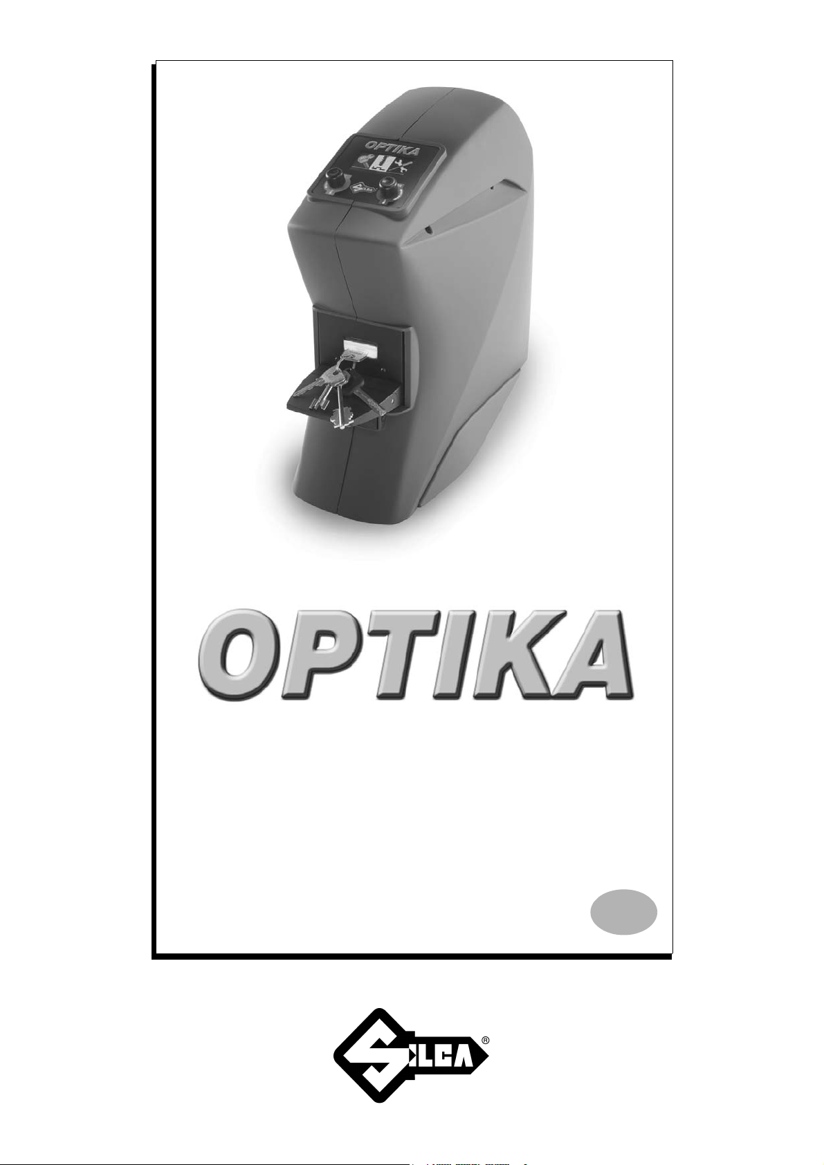
Operating manual
D433712XA
vers. 6.0
EN
Page 2

© 2008 SILCA S.p.A - Vittorio Veneto
This manual has been drawn up by SILCA S.p.A.
All rights reserved. No part of this publication may be rep roduced or used in any form or by any means (pho tocopying,
microfilm or other) without the written permission of SILCA S.p.A.
Edition: February 2017
Printed in Vittorio Veneto
by SILCA S.p.A.
via Podgora, 20 (Z.I.)
31029 VITTORIO VENETO (TV) - Italy
Page 3

INDEX
GUIDE TO CONSULTATION ....................................................................................................................1
GENERAL .................................................................................................................................................. 2
1 TRANSPORT ............................................................................................................................. 3
1.1 Packing ......................................................................................................................... 3
1.2 Transport ...................................................................................................................... 3
1.3 Unpacking the machine ................................................................................................ 3
1.4 Handling the machine ................................................................................................... 3
1.5 Checking for damage .................................................................................................... 3
2 ACCESSORIES PROVIDED ...................................................................................................... 4
3 DESCRIPTION OF DEVICE ....................................................................................................... 5
3.1 Main characteristics ...................................................................................................... 6
3.2 Technical Data ..............................................................................................................6
3.3 Main operating parts ..................................................................................................... 7
4 DEVICE INSTALLATION AND PREPARATION ....................................................................... 8
4.1 Separate Parts ..............................................................................................................8
4.2 Connection to external supply points ............................................................................ 8
4.3 Environmental conditions .............................................................................................. 8
4.4 Positioning .................................................................................................................... 9
4.5 Description of work station ............................................................................................ 9
5 USING OPTIKA ........................................................................................................................ 10
5.1 Optika’s software update ............................................................................................ 10
5.2 Interface flow on the machine ..................................................................................... 10
5.3 Initial operations ..........................................................................................................10
5.4 Fitting or removing the key into or from the clamp ...................................................... 11
5.4.1 Key insertion ................................................................................................................. 12
5.4.2 Bit key insertion with ligth shade device ....................................................................... 12
5.4.3 Key removal .................................................................................................................. 12
5.4.4 Fitting of SHOULDER STOP key with adapter (code D737017ZB) ............................. 14
6 INSTRUCTIONS FOR USE ...................................................................................................... 15
6.1 Key search ..................................................................................................................15
6.1.1 KEY POSITIONING ...................................................................................................... 16
6.1.2 STEP 1: VIEWING THE CUTS .................................................................................... 17
6.1.3 STEP 2: VIEWING THE PROFILE .............................................................................. 18
6.1.4 SPECIAL CASES ......................................................................................................... 21
6.1.5 SUPPLEMENTARY SEARCH DATA ........................................................................... 23
6.1.6 POSSIBLE ERRORS IN THE “KEY SEARCH” FUNCTION ......................................... 25
6.2 Key Matching .............................................................................................................. 26
6.2.1 MATCHING FROM "NEW READING" .......................................................................... 27
6.2.2 MATCHING FROM "LAST READING" ......................................................................... 35
6.2.3 POSSIBLE ERRORS DURING "CUT MATCHING" ..................................................... 35
6.3 Key copy ..................................................................................................................... 37
6.3.1 Transmission from main menu ..................................................................................... 37
6.3.2 Transmission at the end of a search ............................................................................ 38
6.3.3 Possible errors during communication with the key-cutting machine ........................... 38
6.4 Options ....................................................................................................................... 39
Page 4

6.4.1 MACHINE DATA .......................................................................................................... 39
6.4.2 LANGUAGE .................................................................................................................39
6.4.3 USER PROFILES ........................................................................................................ 40
6.4.4 KEYS IN STOCK .......................................................................................................... 41
6.4.5 SEARCH TYPE ............................................................................................................ 41
6.4.6 MATCHING TYPE ........................................................................................................ 41
6.4.7 TEST HARDWARE ...................................................................................................... 42
6.4.7.1 CHECK ADJUSTMENT ......................................................................................... 42
6.4.7.2 CHECK PROFILE AREA ....................................................................................... 43
6.4.7.3 CHECK CUTS AREA .............................................................................................44
6.4.7.4 TELECAMERA and LED ........................................................................................ 44
6.4.7.5 DISPLAY ................................................................................................................44
6.4.7.6 KEYBOARD ........................................................................................................... 44
6.4.8 UPDATING OPTIKA INTERNAL PROGRAM ............................................................... 45
6.4.9 SERVICE MENU .......................................................................................................... 45
7 MAINTENANCE ....................................................................................................................... 46
7.1 Clamp replacement .................................................................................................... 46
7.2 Clamp cleaning ........................................................................................................... 47
7.3 Check machine gauging ............................................................................................. 47
7.4 Knob replacement (ESC/ENTER) ............................................................................... 47
8 DISPOSING OF MACHINE ...................................................................................................... 48
9 AFTER-SALES SERVICE ........................................................................................................ 49
9.1 How to request service ............................................................................................... 49
Appendix 1 -
ELECTRIC DIAGRAMS
.................................................................................... I -IV
Page 5
Optika Operating manual - English
7
8
9
2
1
3
6
4
7
7
3
5
5
5
10
1
9
11
1
1
1
1
GUIDE TO CONSULTATION
This manual has been produced to serve as a guide for users of the
to operate your machine safely and efficiently
.
OPTIKA
device. Read it carefully; it is essential if you wish
Consultation
The contents of the manual are divided into sections relating to
Transport and handling
Machine description and safety
Proper use
Maintenance
.................................................................................................................................. 5-6
................................................................................................................................... 7
...................................................................................................................... 1
........................................................................................................2-3-4
:
Technical terms
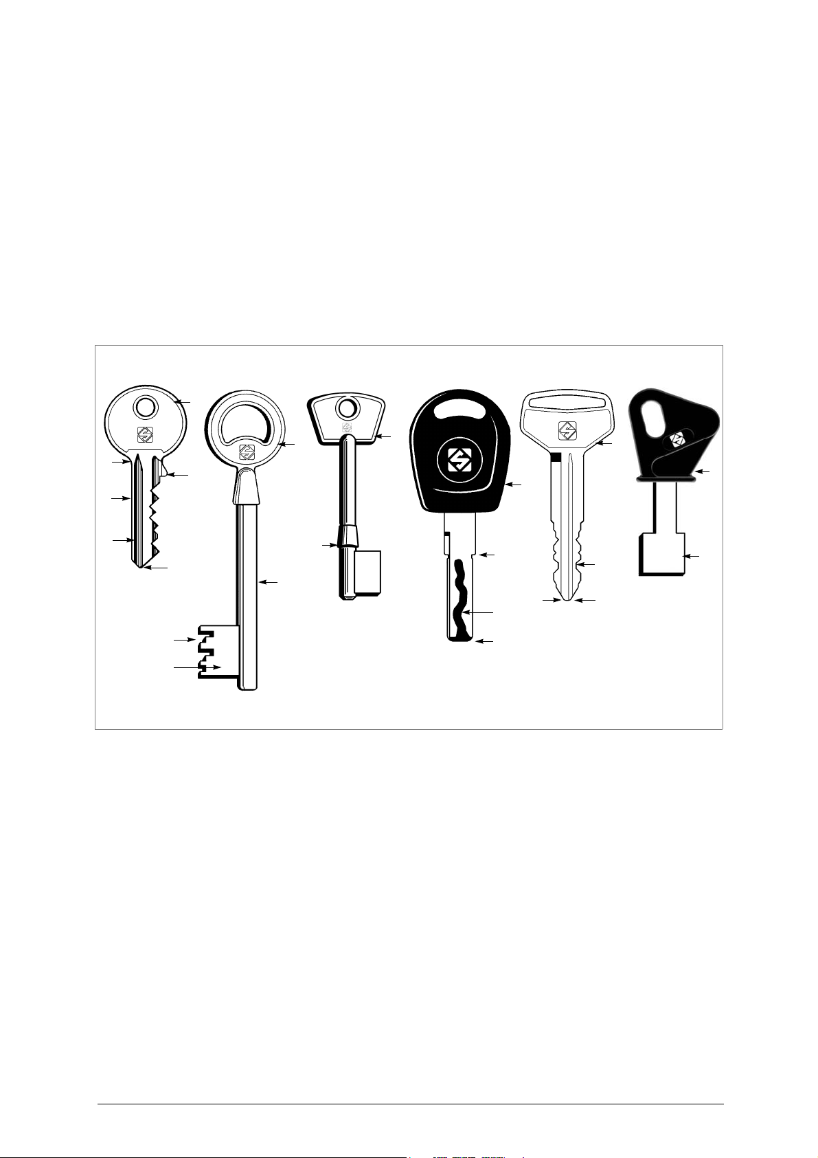
Common technical terms are used in this manual. To assist those with little experience of keys, below is an illustration of the
terms most frequently used
:
Fig. 1
1) Head
2) Neck
3) Shoulder
4) Blade
5) Tip
6) Back
7) Cutting
8) Stem
9) Bit
10)Tip stop
11)Shoulder stop
Copyright Silca 2017 1
Page 6

Operating manual - English Optika
GENERAL
The OPTIKA device has been designed according to the specifications of the Electromagnetic
Compatibility Directives.
From the design stage risks for the operator have been eliminated in all areas: transport, reading,
regulation and maintenance.
The material used in the manufacture of this device and components employed during its use are not
dangerous and render OPTIKA compliant with directives.
Use
Instructions for installation and use of the OPTIKA device are those laid down by the manufacturer.
If the device is used differently or for purposes different from those described in this manual, the
customer will forego any rights he may have over Silca S.p.A. Furthermore, unforeseen danger to the
operator or any third parties may arise from incorrect use of the machine.
Negligence in the use of the machine or failure on the part of the operator to observe the instructions
given in this manual are not covered by the guarantee and the manufacturer declines all responsibility
in such cases.
It is therefore indispensable to read the operating manual carefully in order to make the best use of
the device and benefit from its potential
Instructions manual
The instructions manual provided with the machine is essential to its proper use and to carry out the
necessary maintenance.
We therefore recommend protecting th e ma nual f rom da mage in a saf e shelte red pl ace, easily t o hand
for quick consultation.
.
Further risks
There are no further risks arising from the use of the OPTIKA device.
Protection and safety precautions for the operator
The OPTIKA èdevice is built entirely to the Machine Directive. The operations for which it has been
designed are easily carried out at no risk to the operator.
The adoption of general safety precautions and observance of the instructions provided by the
manufacturer in this manual eliminate all human error, unless deliberate.
The OPTIKA device is designed with features which make it completely safe in all its parts.
• Power supply
The device is powered by electricity through a 15 Vdc universal power supply unit, provided.
Attention: as the device has no master switch, it remains live when connected.
ATTENTION: if the power supply must be cut off, wait at least 10 seconds before re-connecting Optika to the
mains.
• Maintenance
The operations to regulate, service, repair and clean the machine have been devised in the simplest
and safest way possible. There is no danger of removable parts being replaced wrongly or unsafely.
• Software Update
The machine can be updated by RS232 connection to a personal computer or by USB device prepared
with the aid of the Key Reader Program (provided with the machine) or Silca Key Programs.
• Machine identification
The
OPTIKA
device is provided with an identification label that shows the serial number
(fig. 2).
Fig. 2
2 Copyright Silca 2017
(*)
see
ch.8 DISPOSAL, page 48.
Page 7
Optika Operating manual - English
315 mm
600 mm
530 mm
A
D D
B-C
F
E
F
1 TRANSPORT
The
OPTIKA
packed
device is easily transported and is not dangerous to handle. The device can be carried by one person, even when
.
1.1
Fig. 3
Packing
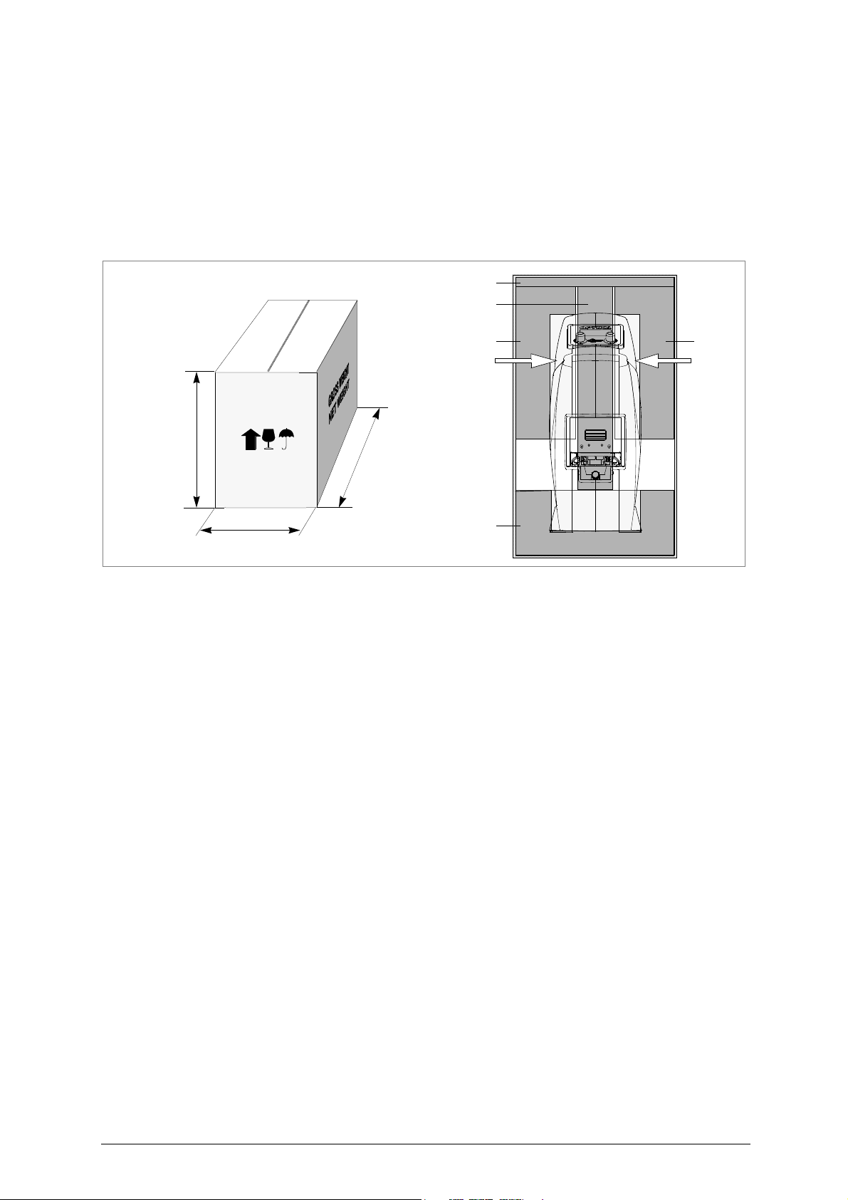
The OPTIKA device is packed in a strong cardboard box, the dimensions of which are shown in fig. 3
sufficiently robust to be used for storing the machine for long periods.
Inside the packing box the device is fully prote ct ed by expanded pol ye thyle ne shells.
The shells and cardboard box ensure safe transportation and protect the machine and all its parts.
1.2 Transport
To avoid damaging the OPTIKA it must always be transported in its packing case. This will prevent
sudden movements or rough handling from damaging the machine, persons or things.
1.3 Unpacking the machine
ATTENTION: if the device comes from a cold environment, to preven t the effect of condensa tion on the devices
lenses it is necessary to wait a few hours before use (unpacking).
To remove the machine from the packing box:
1) Open the box without damaging it so that it may be used again (removals, dispatch to manufacturers
for repairs or servicing).
2) Remove the upper protective panel (A) and the two blocks (B) and (C).
3) Check the contents of the box, which should comprise:
- 1 OPTIKA device enclosed in protective shells
- 1 power supply unit
- 1 accessories kit
- 1 set of documents, including: operating manual, spare parts list and guarantee
4) Take out the 2 side protection shells (D) by pulling them upwards.
5) Grip the two top cavities (F) and lift the machine.
1.4
ATTENTION: never lift the device by holding the clamp opening lever (B) (fig. 7, page 7).
Handling the machine
When the device has been unpacked, place it directly on its workbench.
This operation can be carried out by one person, firmly hold in g the device gri ppi ng the two top ca vi tie s
(F) or the base.
1.5
Checking for damage
OPTIKA is solid and compact and will not normally damage if transport, unpacking and installation have
all been carried out according to the instructions in this manual. However, it is alwa ys advisable to check
that the machine has not suffered any damage.
Copyright Silca 2017 3
Page 8
Operating manual - English Optika
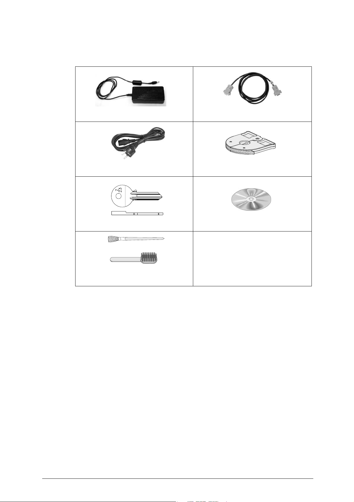
Power supply unit
Serial cable
Power cable
Light shade device
for bit and pump keys
Setting template Z23
CD rom "Key Reader Program"
Cleaning tools
clamp cleaning brush
key cleaning brush
2 ACCESSORIES PROVIDED
The tools provided by Silca are those necessary and sufficient f or carryi ng out the op eratio ns invo lved.
4 Copyright Silca 2017
Page 9
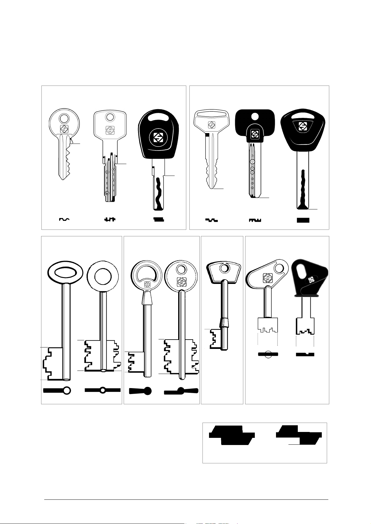
Optika Operating manual - English
flat keys
head stop
flat keys
tip stop
male
bit keys
female
bit keys
keys
pump
**
**
shoulder stop
bit keys
key blank
profile
cut key
profile
3 DESCRIPTION OF DEVICE
OPTIKA is a key-reading device that incorporates high quality performance and precision.
Optika reads a profile and recognises most flat, bit and double bit keys, subject to their being included
in the Silca database.
(*) With a cut key the profile is read properly and
recognized only if the cuts have not touched or
altered the part used for recognition. Example
(fig. 4):
Fig. 4
(**) Shoulder stop keys are managed only in KEY MATCHING mode and need an optional adapter.
Copyright Silca 2017 5
Page 10
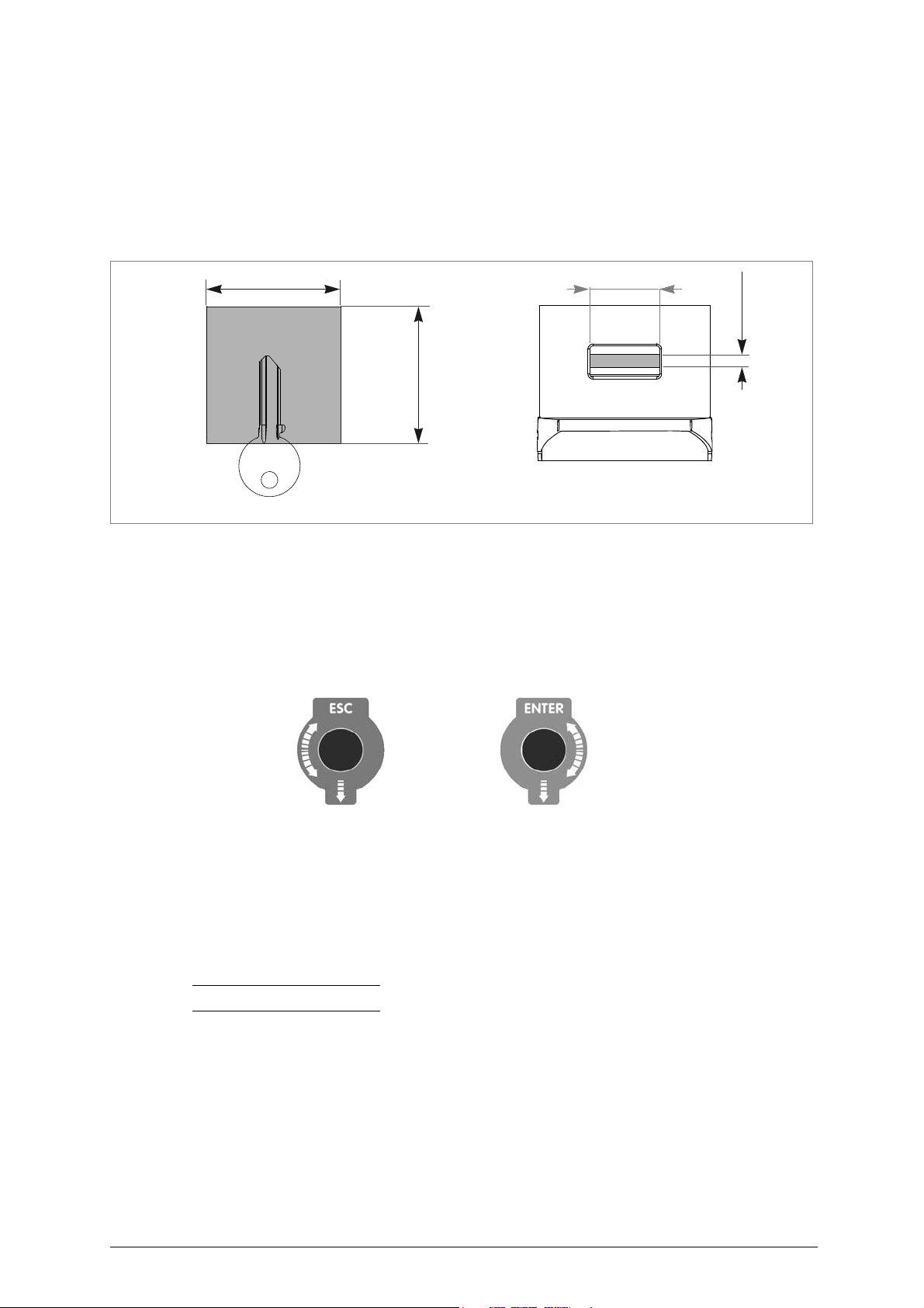
Operating manual - English Optika
max.45mm
max. 40mm
max.8,5mm
Max key thickness
Max. reading area
or stem diameter
max. 40mm
knob/push buttonknob/push button
ENTERESC
3.1 Main characteristics
•KEY CLAMP
The standard clamp is universal and takes all keys provided by Silca.
The clamp is opened and closed by means of a lever (B) (fig. 7, page 7).
The clamp has a rotation system that facilitates alignment of the keys. To rotate the key simply move
the lever to one side (B).
The clamp is easily removed to facilitate cleaning and maintenance operations) (ch. 7.1, page 46).
Fig. 5
Fig. 6
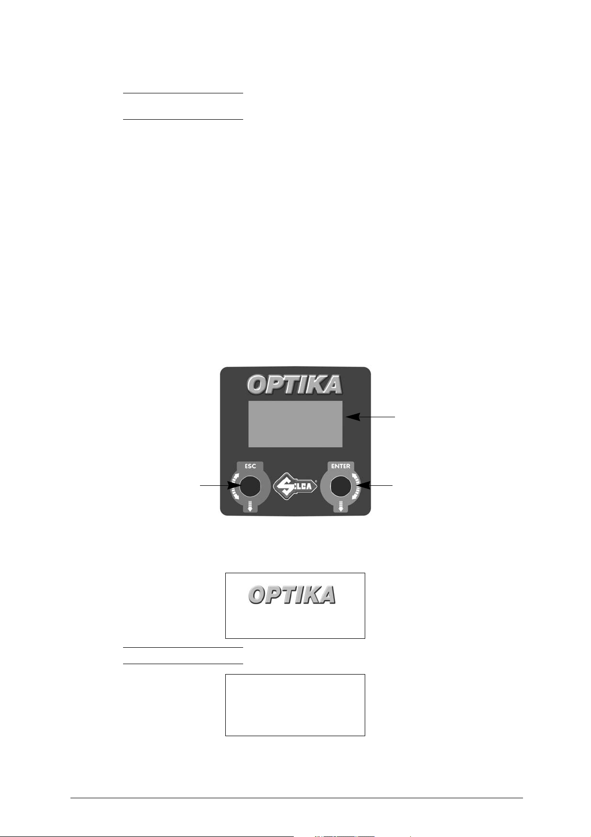
• DISPLAY
The display located on the top of the device comprises 5 lines of 20 characters each.
• CONTROLS
The pointer is moved by rotating the two knobs clockwise or anticlockwise.
- Press ENTER to confirm your choice or the operation in progress.
- Press ESC to go back or abandon the operation in progress.
•STAND BY
When the device is connected and switched on it remains on, as it does not have a master switch. If it
is not used within approximately 5 minutes of switching on, it automatically goes onto stand by, the
display goes black and key illumination goes off. This also happens when the device is left in order to
carry out a search for a key. In any case, just press or rotate one of the 2 knobs to reinstate normal
operation.
Note: the Stand By function has been adopted to safeguard duration of the display.
• DATABASE
The database on the machine is a summary of all the profiles for keys produced by Silca and
recognisable by the device (not the full Silca range).
3.2 Technical Data
DIMENSIONS: width: 190 mm - depth: 480 mm - height: 400 mm
NET WEIGHT: 9Kg.
6 Copyright Silca 2017
Page 11
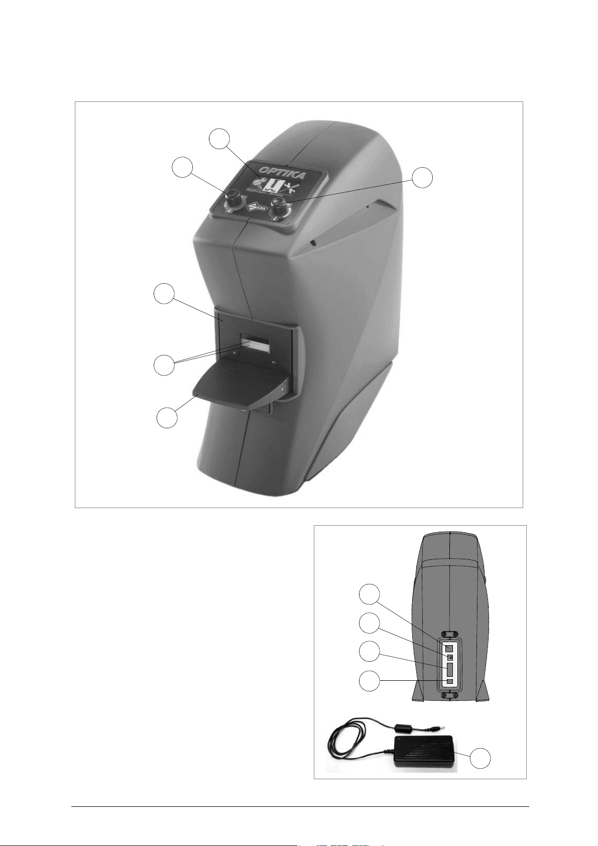
Optika Operating manual - English
B
A
C
E
D
F
M
I
H
G
L
3.3 Main operating parts
Fig. 7
OPTIKA device
A - Key clamp
B - Clamp-opening lever
C- Display
D - ENTER Knob/push button
E - ESC Knob/push button
F - Illuminators
G - Power supply socket
H - Serial receptacle
I - USB receptacle (slave)
L - Double USB receptacle (master)
M - Power supply unit
Fig. 8
Copyright Silca 2017 7
Page 12
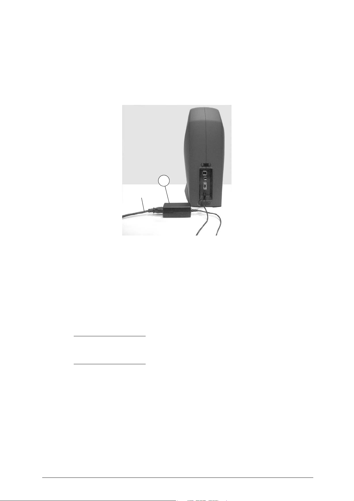
Operating manual - English Optika
M
power supply
cable
4 DEVICE INSTALLATION AND PREPARATION
The device can be installed by the purchaser and does not require any special skills.
However, some checks and preparation for use have to be carried out by the operator.
4.1 Separate Parts
Power supply cable and power supply unit
Connect OPTIKA to the power supply unit (M) and connect to the power source by means of the power
supply cable (fig. 9).
Fig. 9
4.2
Connection to external supply points
For the protection of the device and the operator’s safety it is extremely important to ensure that it is
connected to the power mains with the right voltage and by means of a properly earthed differential
switch.
4.3 Environmental conditions
The OPTIKA device uses a series of instruments whos e operation could be significantly a ffected by the
environment in which they work. The most suitable conditions for the device are:
• Temperature between +10° C e +40° C
• Relative humidity 60% (Max) (without condensation)
• It is in any case advisable to avoid excessively damp or badly ventilated areas.
Note:
like any device using lenses for reading images, whenever the temperature goes suddenly
from low (0°C or lower) to high (20-25°C), the lenses may cloud and condensation form. In such
cases the device must be placed in an area with constant temperature of 20°C if possible, until the
condensation on the lenses evaporates and the device can operate in normal conditions
.
8 Copyright Silca 2017
Page 13

Optika Operating manual - English
200 mm
200 mm
200 mm
4.4 Positioning
Place the
OPTIKA
ATTENTION: position OPTIKA device away from sources of light (spotlights, lamps, etc....).
ATTENTION: it is advisable to place the device in a clean dust-free environment.
To facilitate use and maintenance, leave a clearance of at least 200 mm round the device
Check that the machine is firmly placed and steady; its horizontal position avoids obstacles during
reading.
ATTENTION: make sure the device (power supply unit) voltage is suitable for your power sup ply, which s hould
be earthed and provided with a differential switch.
device on the mat provided, on a solid horizontal worktop suitable for the weight of the machine
(fig. 10).
(9 Kg).
Fig. 10
4.5 Description of work station
The device needs only one operator, who has the following controls at his/her disposal
- display (C);
- knob/push buttons (D) (E);
- clamp (A).
(fig. 7 a pag. 7):
Copyright Silca 2017 9
Page 14
Operating manual - English Optika
push button/knobpush button/knob
ENTERESC
display
5USING OPTIKA
Note: the device may be used in Stand Alone mode or with the KEY READER PROGRAM provided
with the machine.
The KRP program completes the machine functions by facilitating operations that would be difficult to
manage through the device keypad and display.
Such operations are:
• Assigning hook positions to customer key blank lists
• Preparing and running lists (filters) for own key stores
• Searching for profiles with more sophisticated filters (e.g. setting exact stem length...)
• Enlarging views of comparisons of profiles read with those in the Silca database.
• Updating Optika internal program.
5.1 Optika’s software update
To update Optika’s software, refer to instructions in chapter ch. 6.4.8, page 45.
5.2 Interface flow on the machine
Optika comes with:
- a graphics display of 5 lines and 20 characters
- 2 knobs/push buttons that move the display pointer up/down, right/left; functions are confirmed by
pressing the knobs.
Fig. 11
5.3 Initial operations
When the device is turned on, the display will show the following message:
Ver.Sw: 1.00.001
Ver.DB: 1.00
Note: only on initial start, the display will show the following message:
Italian
*English
French
German
Spanish
- Turn the ENTER knob clockwise and/or anticlockwise to scroll and select the various languages.
- Press the ENTER knob to confirm the selected language.
- After 20 seconds the display will show the device SW version and a message to wait for data loading
to be completed.
10 Copyright Silca 2017
Page 15
Optika Operating manual - English
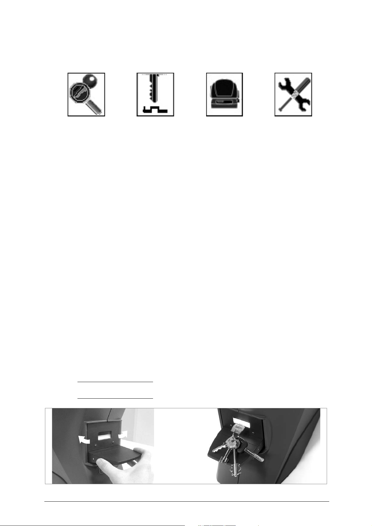
- After a further 10 seconds the display will show the symbols for the functions involved:
Key search Key matching Key copy Options
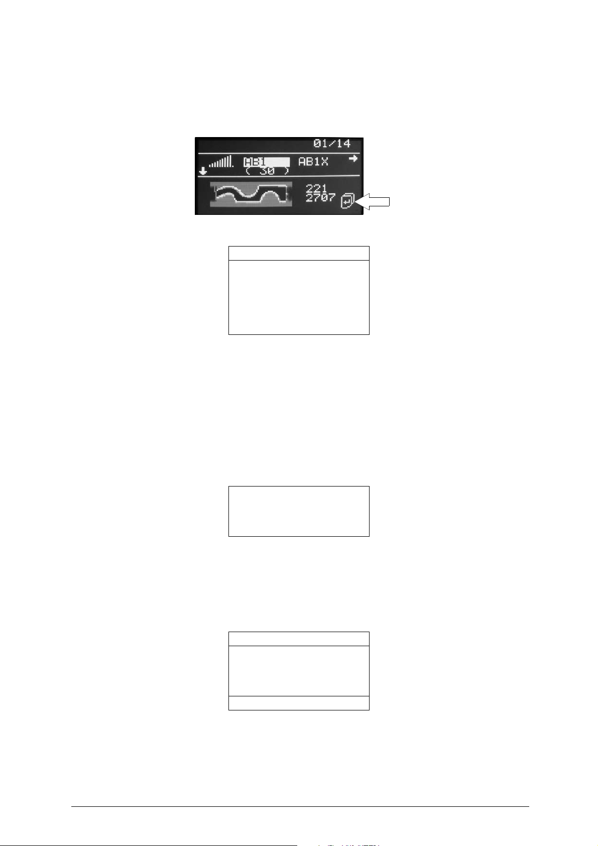
The display shows the first function of ’
- To enter one of the 4 functions in the menu, just turn the ENTER push button/knob to select the
function (illuminated symbol and description) then press the ENTER push button.
- Press the ESC push button to leave the function.
Key search
’ already selected.
5.4 Fitting or removing the key into or from the clamp
WARNINGS
To read the key and use the machine properly remember that:
• To avoid condensations on the devices lenses, it is recommended to not move the
device from a cold environment to a warm environment. If this is the case, it is
recommended to wait a few hours before use of the device.
• The key must be carefully cleaned. Any residue on the profile, such as grease,
deposits, filaments, dust or whatever, may cause errors (use the brush provided).
• The key must be of the required type (see ch.3).
• The key must not be all black (plastic or surface treat ment).
• For bit, double bit and pump keys the light shade adapter must be fitted.
• For bit keys with shoulder stop use the special adapter f or reading cuts and do not
use the light shield adapter, as profile reading and searching for this type of key are
not managed.
• The key must be intact. If it is broken it must have a regular profile.
• The key must not be bent or twisted and the part to be read must be free of dents
(especially bumps in the material on the tip, or burrs).
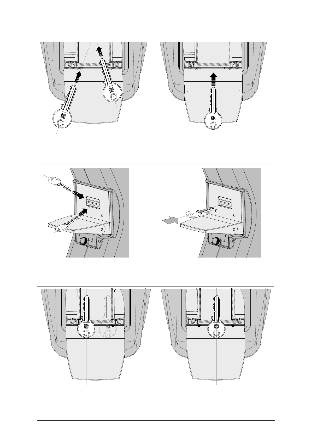
• The key must be fitted into the centre of the clamp and not sloping (fig. 17). Make
sure it is not facing too far to the right or left (fig. 18).
• If the key is one of a bunch, it can still be read, as long as the clamp functions and
the key position are not affected.
• Only keys can be fitted into the Optika device clamp (for maximum dimensions see
fig. 5, page 6).
Fitting
Fig. 12
Note: make sure the clamp (which can be opened and rotated) is well centred and not turned fully
left or right (fig. 12).
Copyright Silca 2017 11
Page 16

Operating manual - English Optika
5.4.1 Key insertion
1) Take hold of the key head with one hand and with the
other lower the clamp opening lever (fig. 13).
2) With the clamp open fit the key, taking care that:
- the key is well centred on the clamp (not too far to
the right or left) (fig. 18).
- it is aligned as well as possible (not turned right or
left) (fig. 16).
3) For bit keys make sure the key head is aligned
horizontally (see fig. 23, page 18).
Fig. 13
5.4.2 Bit key insertion with ligth shade device
Opening the light shade device:
Hold the side of the adapter and lift
the closing tab.
Closing the light shade device:
Insert the key to be dimmed and
close the adapter by lowering the
lever until it clicks into place.
Fig. 14 - light shade device
5.4.3 Key removal
Removing
Note: the key must be removed only when the
clamp is open. Removing it with the clamp
closed will damage the illuminators and the key
plate (glass).
1) Take hold of the key head with one hand and
with the other lower the clamp opening lever
(fig. 15).
2) With the clamp open, lift the key in it so that the
glass plate is not scratched and remove the
key.
3) Release the clamp opening lever.
Fig. 15
12 Copyright Silca 2017
Page 17
Optika Operating manual - English
NO! YES
NO! YES
NO! YES
Fig. 16
Fig. 17
Fig. 18
Copyright Silca 2017 13
Page 18
Operating manual - English Optika
adapter for
shoulder stop keys
D737017ZB
B
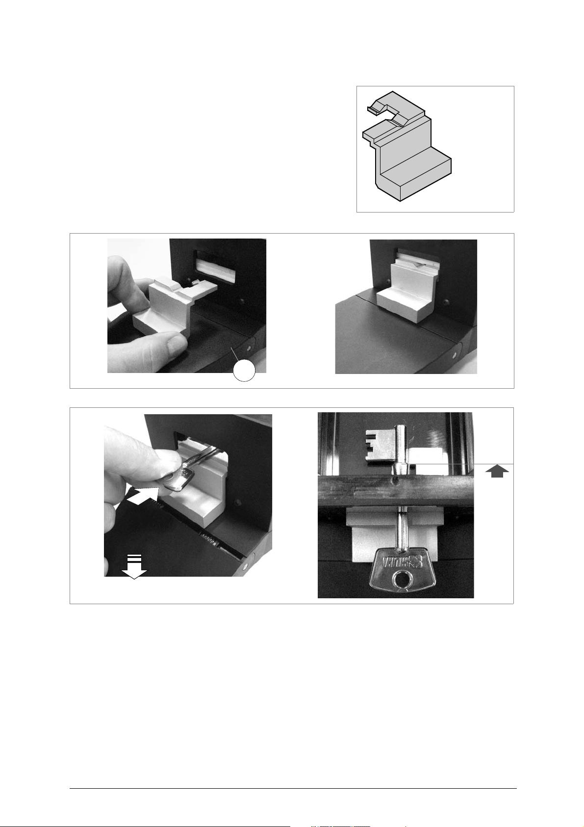
5.4.4 Fitting of SHOULDER STOP key with adapter (code D737017ZB)
1) Lower the lever (B) on the clamp and fit the adapter all
the wayup against the illuminators (fig. 20).
2) With the lever down fit the key with its stop up against the
stop on the adapter (fig. 21).
ATTENTION: the bit must be facing left.
3) Release the lever and proceed with the operation in
question.
Fig. 19
Fig. 20
Fig. 21
14 Copyright Silca 2017
Page 19
Optika Operating manual - English
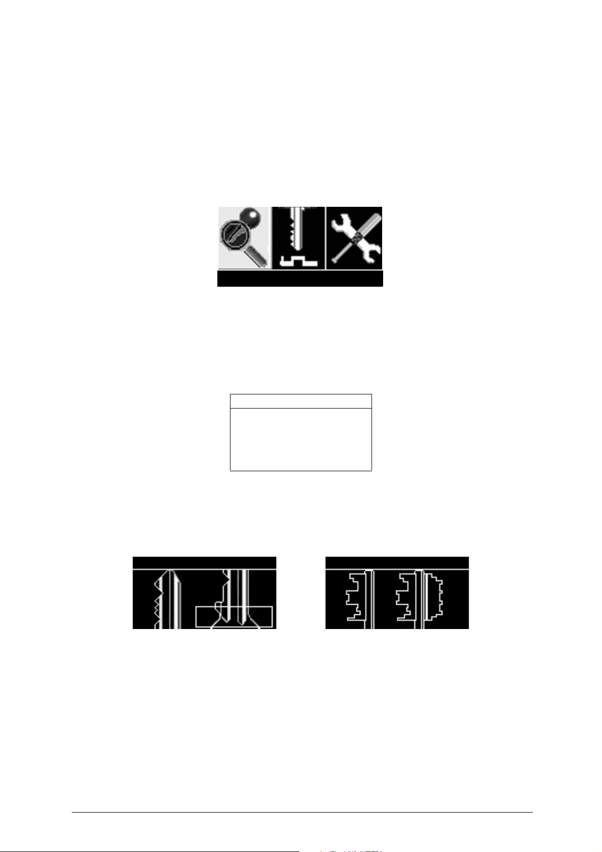
Key search
Insert the key
Insert the key
6 INSTRUCTIONS FOR USE
The main functions that can be carried out on the OPTIKA device are:
- KEY SEARCH
- KEY MATCHING
- KEY COPY
- OPTIONS
6.1 Key search
• This function is used to detect/check the profile of an original key and find the corresponding
reference if it is included in the Silca database.
• This function is used to detect the profile of a spare key (not Silca) when the Silca comparatives a re
not known, by finding the corresponding reference (if in the Silca database).
• This function also reads cuts that can be used in the “Key Comparison” function.
Press ENTER; the display will show:
Select key type:
Flat - Shoulder stop
Flat - Tip stop
Bit male
Bit female
Pump
Turn the ENTER knob to select the type of key to be searched for (the descrip tion will be highli ghted by
a yellow strip over black characters.
Press the ENTER button and the display will show the message (the same for all types of keys):
Flat keys Bit keys
Copyright Silca 2017 15
Page 20
Operating manual - English Optika
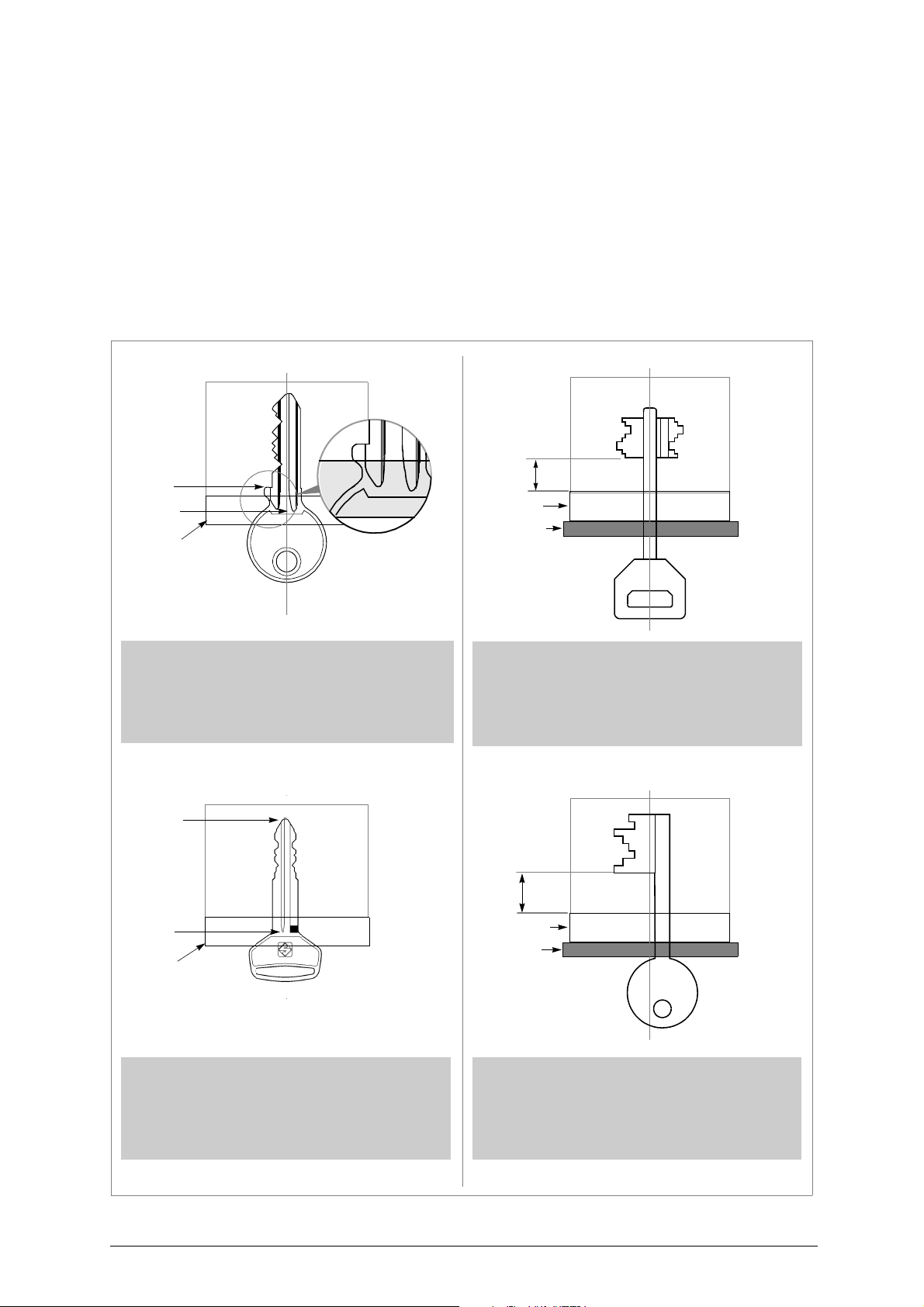
Example: FLAT - SHOULDER STOP Example: DOUBLE BIT KEY
illuminators
illuminators
oscuratore
key stop
end of milled
channels
-
The key stop must be past the illuminators
.
-
The end of milled channels must be beneath
the illuminators
.
-
The bitting of single side keys must face left
.
-
The bit must go past the illuminators
.
-
A minimum of 10 mm. of stem must be
inserted
.
-
The key stem must be entirely surrounded by
the light shade device
.
Example: FLAT - TIP STOP Example: BIT KEY
illuminators
illuminators
light shade
end of milled
channels
-
The end of milled channels must be beneath
the illuminators
.
-
The bitting of single side keys must face left
.
-
The bit must go past the illuminators
.
-
A minimum of 10 mm. of stem must be
inserted
.
-
The key stem must be entirely surrounded by
the light shade device
.
key stop
min.
10 mm
device
min.
10 mm
6.1.1 KEY POSITIONING
Flat - Shoulder stop
Flat - Tip stop
Bit male (with light shade device)
Bit female (with light shade device)
Pump (with light shade device)
ATTENTION: the key must be carefully cleaned. Any residue on the profile, such as grease, deposits, filaments,
dust or whatever, may cause errors (use the brush provided).
Flat keys Bit keys
16 Copyright Silca 2017
Page 21
Optika Operating manual - English
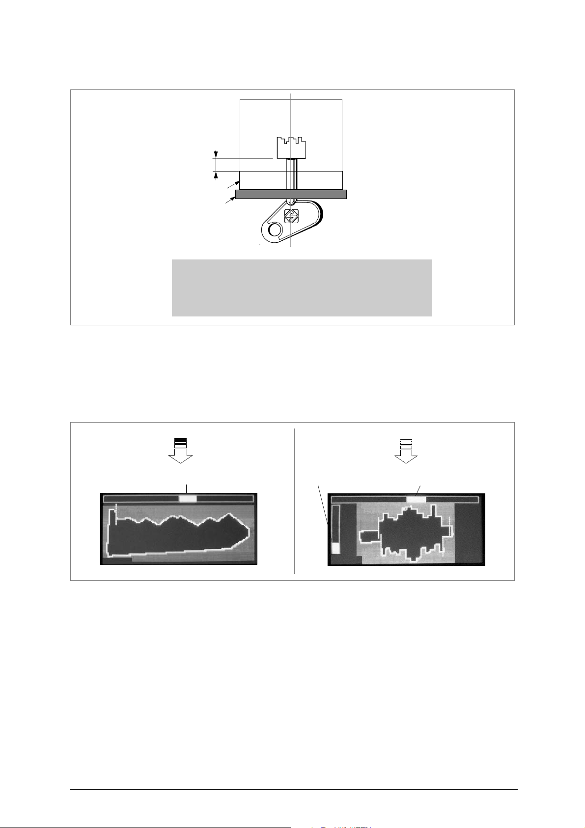
light shade
illuminators
-
The bit must go past the illuminators
.
-
A minimum of 10 mm. of stem must be inserted
.
-
The key stem must be entirely surrounded by the light
shade device
.
min.
10 mm
devixe
key alignment bar
key alignment bar
L:2707
L:2419
key-fitting bar
Pump keys
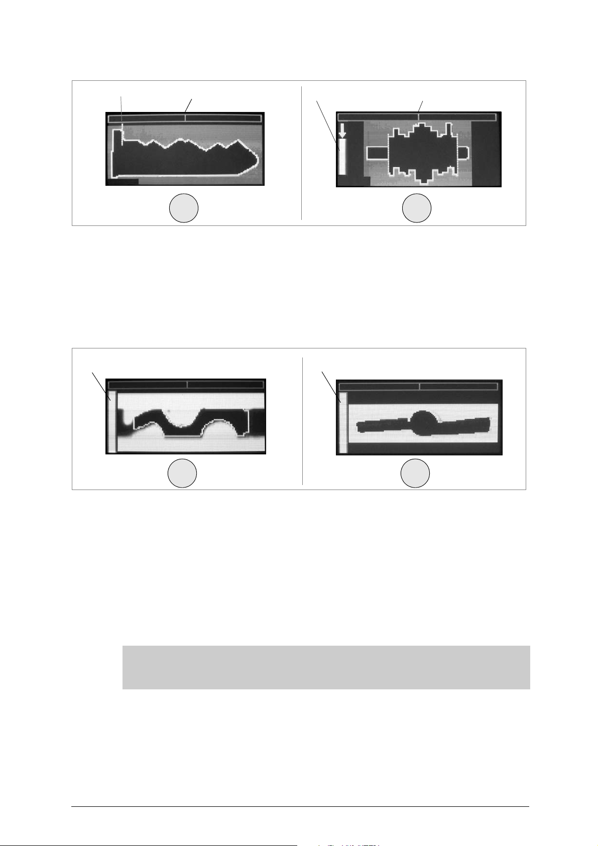
After inserting the key involved, the display will sho w a plan view of the key (turn the ENTER knob to
change the view from horiz ontal to vertical and vice v ersa). Make sure the stop detector line/pointer
(hatched) is the right position and that the top key alignment bar is as fine as possible (fig. 22).
6.1.2 STEP 1: VIEWING THE CUTS
• If the key stop cannot be seen in the flat key view on the display, the pointer will flash and be
approximately in the centre of the display. Just push the key head slightly so that the key advances
well into the clamp.
• If in the view of the key on the display (male and female bit) the left-hand bar (referred to inserted
key) is not fully upwards, try pushing the key head gently to insert the key into the clamp.
• When the fitting bar is fully up, do not push the key any further.
• If the top bar shown on the display is not a fine line, turn the clamp slightly to the right or left until it
appears as required.
• The better alignment, the better reading will be of stem or bit length.
Copyright Silca 2017 17
Page 22
Operating manual - English Optika
stop detector line
key alignment bar
key alignment bar
ENTER ENTER
L:2419
L:2707
key-fitting bar
left-hand bar (profile luminosity) left-hand bar (profile luminosity)
ENTER ENTER
Fig. 22
- Before confirming the reading, press the ENTER button and make sure the key is actually aligned
(the top yellow bar should be just a vertical line and the left-hand yellow bar should point upwards as
much as possible).
-
A downward arrow on the insertion bar (left) indicates that the key has been inserted too far inside
It is advised to gradually pull out the key until the arrow no longer appears
- Press the ENTER push button and the display will show a new image.
.
6.1.3 STEP 2: VIEWING THE PROFILE
.
Fig. 23
If the left-hand bar (referred to the luminosity of the profile) on the display is not
completely upwards, lightly push the key head so that it advances well into the
clamp, or pull it out slightly.
The end of milled channels must be beneath the illuminators in any case. Sometimes the profile and the surface condition of the key do not allow it to extend completely (the left-hand bar could be half-way). With a left-han d bar below
70% of the total, key recognition is either not good and/or wrong.
If the upper bar is not a thin line on the display, turn the clamp/key slightly right
or left until it reaches the best possible condition.
However, it is important that the outline of the profile is well defined; at times it is necessary to find a compromise between the thickness of the upper alignment bar and the image of the profile.
18 Copyright Silca 2017
Page 23
Optika Operating manual - English
ENTER
Groups of keys found
Identical keys
(profile, stem, bit)
ESC
2nd group
1st group
Key thickness or
stem diameter
Bit length or stem length
from stop to tip
Supplemental data
graduated scale
Profile compatibility
Hook position
Fig. 24
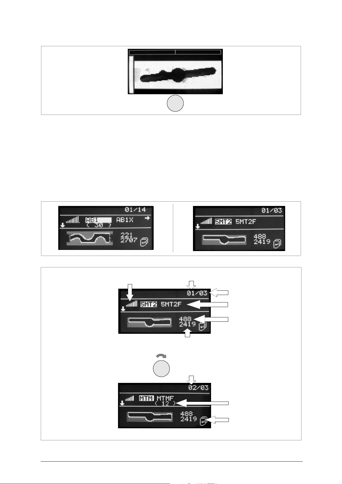
• For bit keys, if the profile appear s to slope (fig. 24), it must be aligned horizont ally so that the
cuts can be read properly.
- If the key has been rotated a great deal to do this, the previous step MUST be repeated
(“view cuts”) so that cut sizes can be read properly.
- Then, turn the clamp/key slightly to the left or right until the top bar shows a thin line (fig.
23). Make sure the profile outline is well defined with reference to the “profile luminosity
bar”.
- Press the ENTER button to start a search. A few seconds later the display will s how the res ult of the
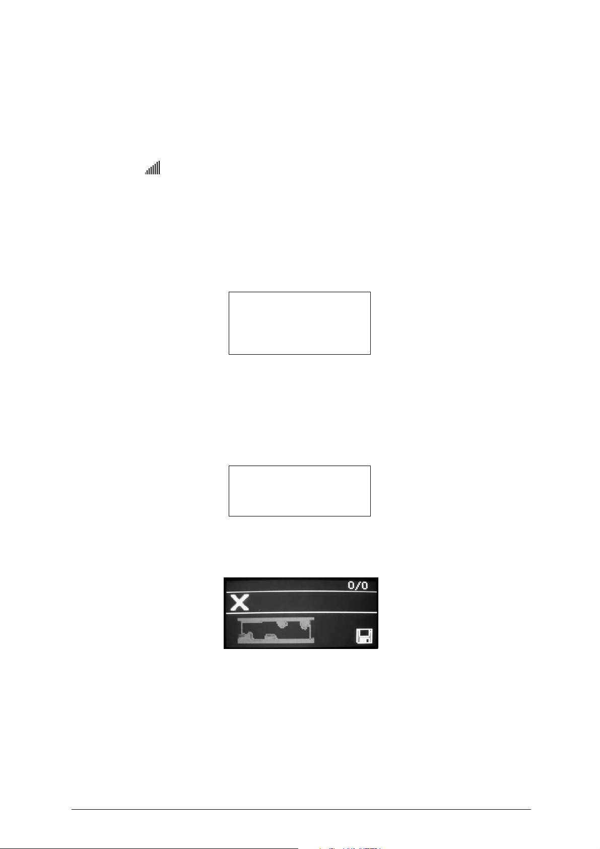
search, comprising a list of the keys found. Examples:
Fig. 25
Fig. 26
Copyright Silca 2017 19
Page 24
Operating manual - English Optika
• Identical keys (same profile and stem length or bit length) will be shown on the same line,
separated by a space (fig. 26).
• Characters in brackets [E.g.: (A001), (A002) etc...] under the name of the key will blank show
the hook number (if entered by an operator using the "Key Reader program" from a PC).
• 01/03 = first group of 3 found (fig. 26)
1st group = highly compatible (see graduated scale)
next groups = quite or not very compatible
graduated scale = the more it’s extended, the more compatible the profile is
Viewing groups and key blanks
•
ESC knob rotation scrolls the group of keys (clockwise scrolls down, anticlockwise scrolls up
•
ENTER knob rotation scrolls the key blanks in the same group (anticlockwise scrolls left, clockwise
scrolls right
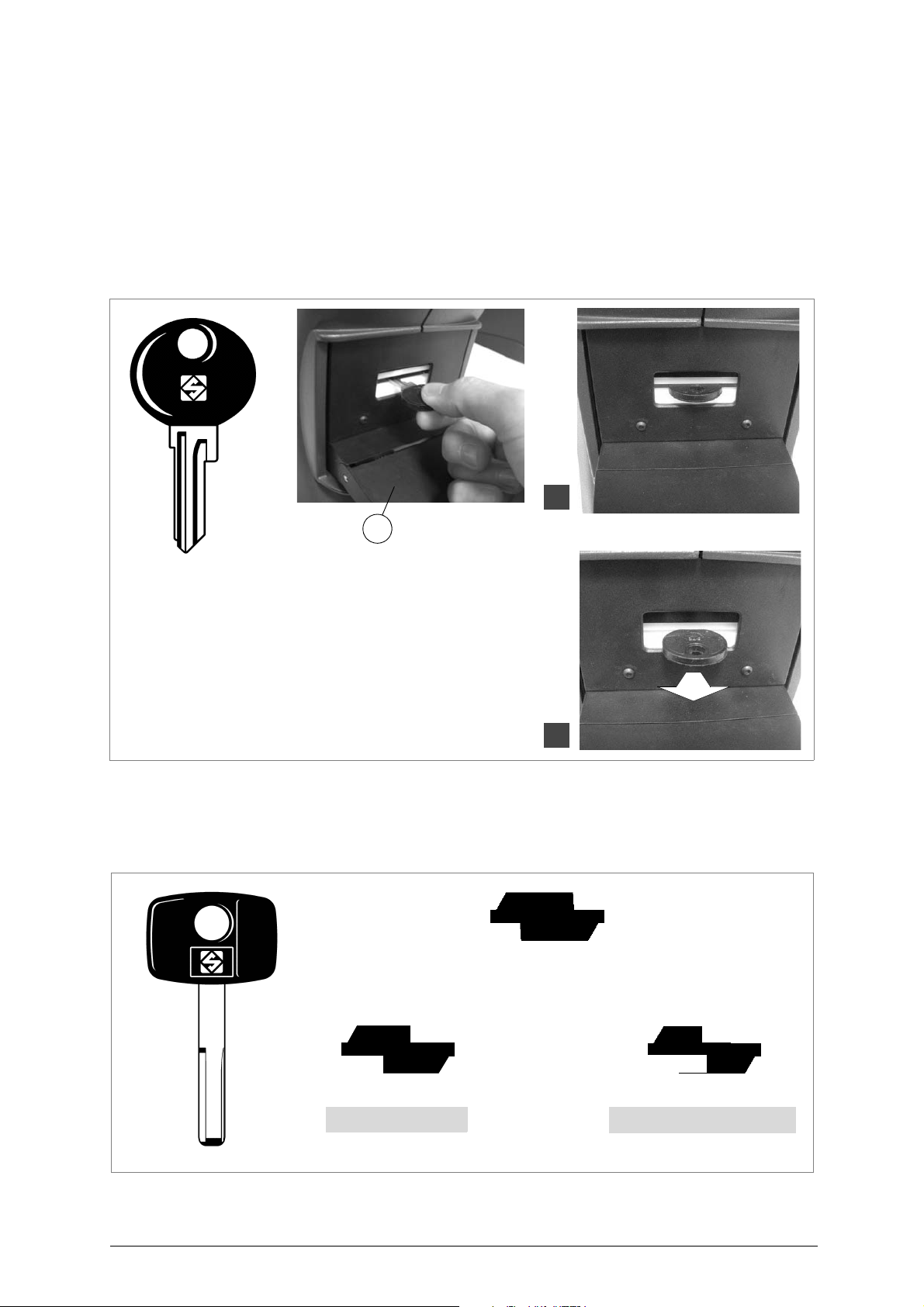
If the first search gives no results the display will show the following message:
).
The reading of the
profile is not
precise.
Reposition the key
and read again
).
The search has produced no results. Among possible causes
-
incorrect positioning of the key
-
search parameters too strict
-
no Silca reference matches the key blank read
It is advised to correctly reposition the key by following all the instructions previously explained (see
ch.6.1.1)
If the second search produces no results, the following message will appear
and read the key again
.
No key found!
Press ENTER
broader search
,
,
to start a
:
:
By pressing ENTER, a search with temporarily broader parameters will be
launched ( the original parameters are never modified
If the broad search produces no results the following display will appear
).
:
At this point the search has not been able to find any proper reference among Silca or User profiles.
It is advised to save the profile as a User Profile if it is to be included in the Database as a reference
for upcoming searches
20 Copyright Silca 2017
.
Page 25
Optika Operating manual - English
B
1
2
KEY-BLANK profile
CUT key profile
search result: OK
CUT key profile
search result: NEGATIVE
6.1.4 SPECIAL CASES
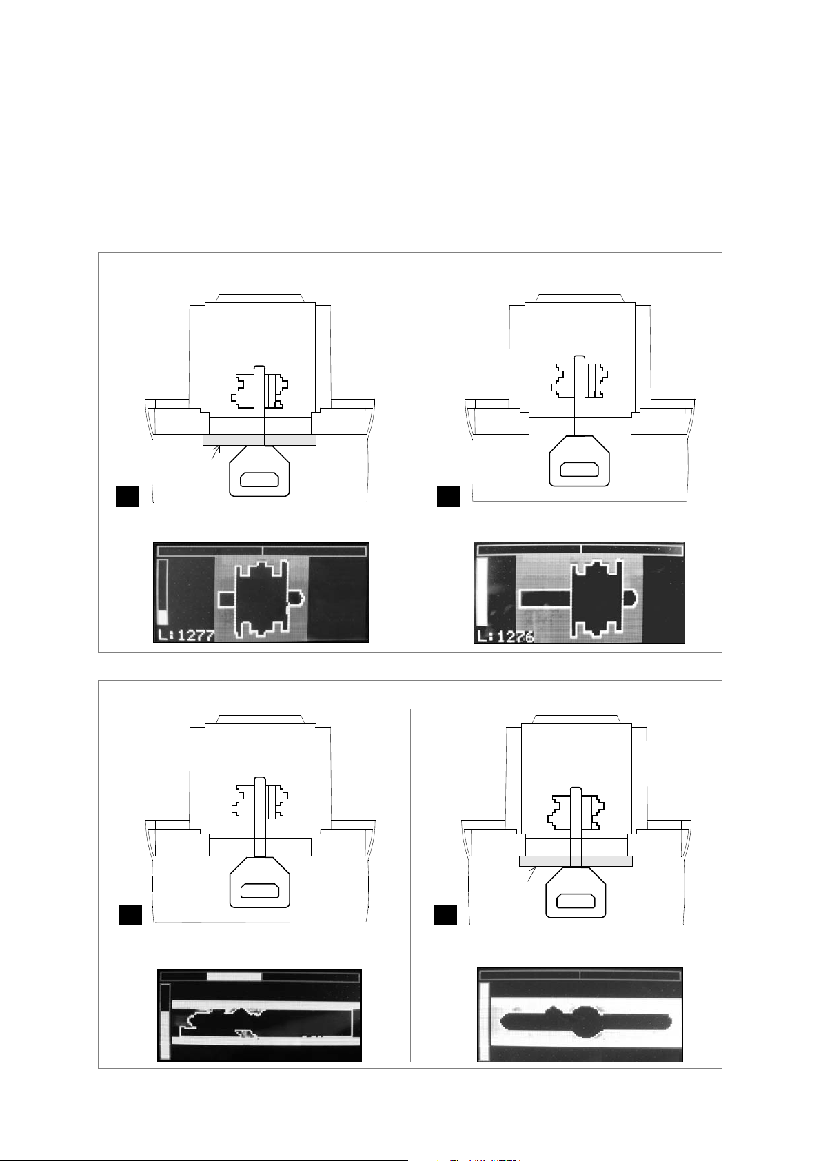
a) SMALL FLAT KEY - HEAD STOP (WITH PLASTIC HEAD)
If the distance between the end of th e plast ic part a nd the stop is smal l, im pedin g prop er vi ewing of the
stop cursor, proceed as follows:
1) Lower the clamp-opening lever (B) and without exerting pressure fit the key into the clamp until the
stop is visible (fig. 27-1) and the cursor is in the right position.
2) Align the upper bar and press ENTER; in this way the stem length reading is precise.
3) Pull the key out slightly (
the alignment bar centred and illumination bar up, press ENTER.
fig. 27-
2), release the clamp-opening lever to keep the key in place, then with
Fig. 27
Fig. 28
b) VEHICLE KEY WITH LASER TYPE CUTS
With a cut key the profile is read properly and recognized only if the cuts have not touched or altered
the part used for recognition.
Copyright Silca 2017 21
Page 26
Operating manual - English Optika
oscuratore
adattatore
BA
NO YES
STEP 1: Viewing the CUTS
device
light shade
A B
NO
YES
STEP 2: Viewing the PROFILE
c) SHORT-STEMMED MALE AND FEMALE BIT KEYS
If the distance between the end of the bit and the light shade device is small (short stem) and
when reading the cuts the left-hand bar cannot face fully upwards (re ferred to inserted key), proceed as follows:
1) STEP 1: fit the key into the clamp with out the light sh ade device an d try to view a sufficient a mount
of stem (fig. 29-B).
2) press ENTER.
3) remove the key and fit the light shade device.
4) STEP 2: fit the key again with the light shade device (fig. 30-B) and press ENTER.
Fig. 29
Fig. 30
22 Copyright Silca 2017
Page 27
Optika Operating manual - English
Supplemental data
d) PUMP KEY WITH EXTRA SHORT STEM
For pump keys with extra short stems we suggest using the procedure described above.
6.1.5 SUPPLEMENTARY SEARCH DATA
After "Key search" press ENTER, the following display will appear:
Menu selection:
Key copy
Ignore length
Profile info
Save profile
Search by key Manuf.
Search types
1 - KEY COPY
When this function is enabled it is used to transmit the cutting data for a bit key to the IDEA electronic
key-cutting machine to make one or more copies. For further det ails about thi s function co nsult ch. 6.3,
page 37.
2 - IGNORE LENGTH
This function allows to repeat a search ignoring the bit or stem length.
It is particularly useful when the stem or bit length is altered.
The function is only available for shoulder sto p flat keys an d all types of bi t, dou ble bit a nd pum p ke ys.
By pressing ENTER the following message will appear:
The search will
be repeated without
considering bit
length
Press ENTER to start the search
.
3 - PROFILE INFO
Press ENTER, a list will appear of references to spare key manufacturers different from the Silca
reference blank (found by searching with Optika) and highlighted on the last line on the bottom of the
display:
Comparatives
ERREBI :AU5D
BOERKEY :743L
ORION :ABS17
LOTUS :U20
AB1 : SILCA
Turn the ENTER knob
-
to scroll the list of comparatives.
Copyright Silca 2017 23
Page 28

Operating manual - English Optika
- Press ENTER, a list will appear of alternative articles:
Alternatives
AB1X
AB1BZ
AB1Q
AB1DA
AB1 : SILCA
4 - SAVE PROFILE
The following display will appear:
Save read profile
Name:
Make:
Hook:
1) Turn the ENTER knob to select the field into which the data w ill be entered.
- The selected field will be highlighted in yellow.
2) Press ENTER; the display will show a list of characters:
A B C D E F G
H I J K L M N
O P Q R S T U
V W X Y Z 0 1
2 3 4 5 6 7 8
9 - % / & _ #
• Turn the left-hand ESC knob to scroll the fields up and down.
• Turn the right-hand ENTER knob to scroll the fields from left to right; choose the character and press
ENTER to confirm.
- Going on to the next character the proposed letter is the last one selected.
- Characters permitted:
Name: 0123456789ABCDEFGHILMNOPQRSTUVZXYWKJ-%/&_
Make: 0123456789ABCDEFGHILMNOPQRSTUVZXYWKJ-%/&_
Hook: 0123456789ABCDEFGHILMNOPQRSTUVZXYWKJ-%/&_
- MAX limit for fields:
Name: max 14 characters
Make: max 14 characters
Hook: max 8 characters
• To delete the last edited character:
- select the "#" character, bottom right of the display and press ENTER .
• To save a text:
- press ESC to exit, then press ENTER to confirm.
• To save a read profile:
- select the “Save” symbol (disk) and highlight by turning the ENTER knob, then press the kno b in.
A new key blank can be saved with an existing name, which will be overwritten by the new reading.
The key blank name is required (at least one character).
The key blank name must be uniqu e in the da tabase. Key blan ks with the same name cann ot be used.
Note: if no name is given to a key blank, it will not be saved.
24 Copyright Silca 2017
Page 29

Optika Operating manual - English
5 - SEARCH by KEY MANUFACTURER
Used to filter the results of a search by cylinder or lock ma ke (manuf acturer). In this way the resu lt from
possible Silca references is more selective.
To quit the function Search by Make without keeping the set make, press the ESC button repeatedly
until the initial menu appears.
- open a window with the current choice highlighted.
- use the ESC knob to scroll the initials that trigger updating of the list, with the first make starting with
the selected letter highlighted.
- use the ENTER knob to scroll makes in alphabetical order.
- use the ENTER knob to select the MAKE filter.
Search by key Manuf.
296
333
4TR
606
=>A
After selecting the Make filter a search is launched for the profil e previously loaded with the new criterion
or set filter.
If there is no result after a search by make, the possible condition is:
• The key is a new original one not yet produced by Silca S.p.A.
The profile of a loaded key can be saved by associating it to its manufacturer.
6 - SEARCH TYPE
Press ENTER to view the message:
Select search type:
Fine
*Standard
Extended
- Turn the ENTER knob to select the required setting. Press ENTER to confirm the setting (the display
will also show the selection symbol).
- Press ESC to return to the previous menu, and press again to repeat the search using the parameters
of the new setting selected.
Note: in the case of a search type different from the previously selected one, in order to make the
new option operative the search for a key must be started again from the initial menu.
6.1.6 POSSIBLE ERRORS IN THE “KEY SEARCH” FUNCTION
Insert the key
with the bit
to the left
Appears if the bit or flat key is single sided and the bitting is facing right.
Remove the key and insert it with the bitting facing left
.
The reading of the
profile is not
precise.
Reposition the key
and read again
Appears if the reading of the profile inserted is not precise due to wrong positioning
Position the key correctly and read again
Copyright Silca 2017 25
.
[see ch.6.1.1]
Page 30
Operating manual - English Optika
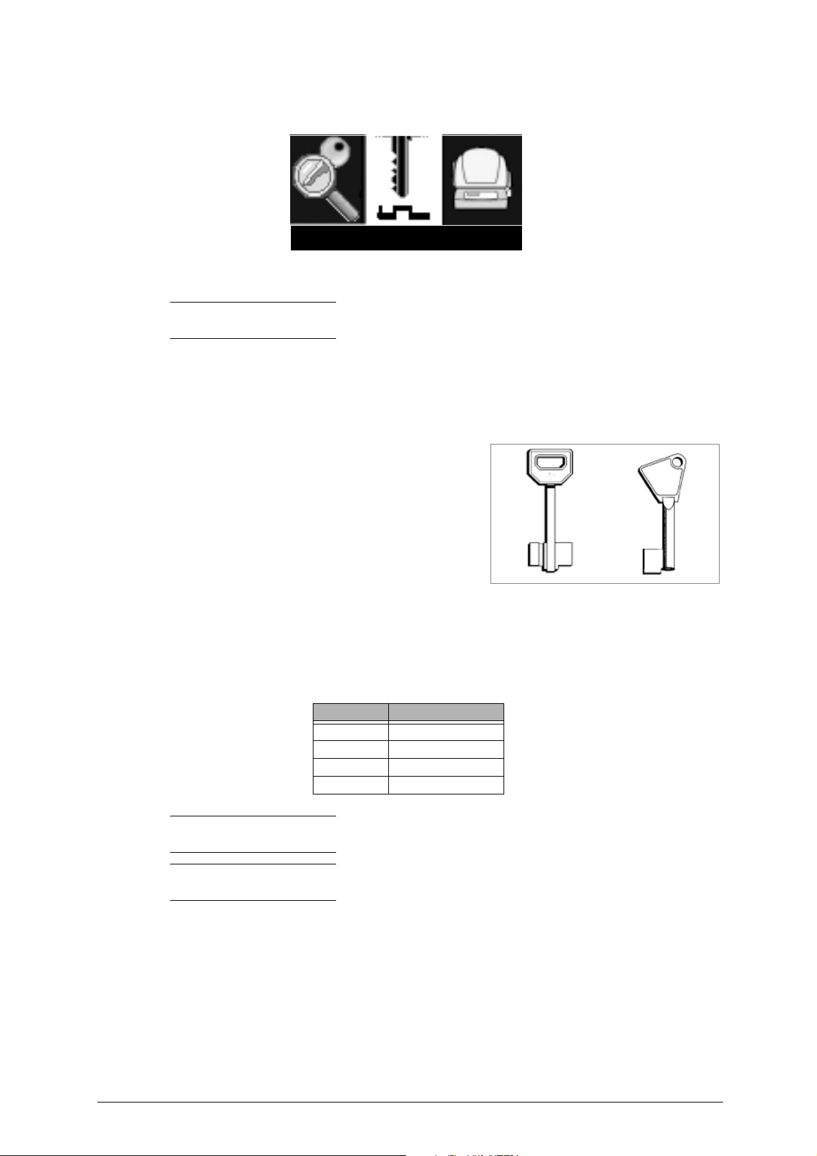
Key matching
6.2 Key Matching
Function used to compare (assess) the difference i n the cutt in g value s of on e o r mo re cu t keys wi th an
original key. The function also checks compatibility of the key profile with the original.
Note: the device detects and indicates the differences found, and doe s not give a result regar ding
the functionality of the cut key.
ATTENTION:the key matching function is currently not available for key types:
• Flat (for cylinders or vehicles) with dou ble as ym met rica l cu ts (d iffe rent cuts on the 2 s ides).
• Dimple keys
• Laser type keys
• Special bit keys (special female front stop and
special square stem) with unusual stem s or bits:
• Bit keys with shoulder stop
This type of key is run only in “Key matching” and “Key copy” modes and requires the use of a special
adapter. Use of the adapter is explained in ch. 5.4.4, page 14.
• Special keys as indicated in the following chart:
Make Silca Ref.
Abloy A Y1, AY2 ....
Abus AB32, AB38P ...
Ford FO19P, FO21P ...
Tibbe TBE1P, TBE2P ...
Note: as these keys are duplicates, make sure they are carefully cleaned (profile and cuts) (use the
brush provided).
Note: for more accurate cut comparisons, follow all the key fitting procedures in ch.5 and all the
instructions in ch.6.
26 Copyright Silca 2017
Page 31
Optika Operating manual - English
Insert original keyInsert original key
L:2707
key alignment bar
L:2419
key alignment bar
key-fitting bar
left-hand bar (profile luminosity) left-hand bar (profile luminosity)
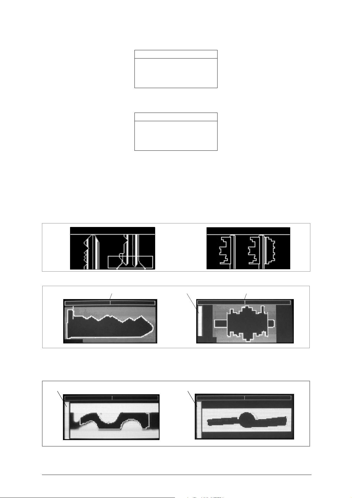
1) Press ENTER, the display will show:
Select key type:
Flat - Shoulder stop
Flat - Tip stop
Bit male
Bit female
2) Turn the ENTER knob to select the type of key to be searched for (the description will be highlighted
by a yellow strip over black characters).
3) Press the ENTER button and the display will show the message (the same for all types of keys):
Matching key from:
Last reading
New reading
There are 2 ways of using “Compare Cuts”.
• Select "New Reading" when in Optika’s memory there is NOT a read key, useful for the comparison.
• Select "Last Reading" when in Optika’s memory there is a read key, useful for the comparison.
6.2.1 MATCHING FROM "NEW READING"
4) Turn the ENTER knob to "New reading" and press ENTER to confirm; the display will show:
5) Fit the original key.
Fig. 31
6) Before confirming the reading operation, press the ENTER button to make sure the key is properly
aligned (the top yellow bar must be just a vertical line). If not, follow the instructions in ch.6.1.
7) Confirm with ENTER, a few seconds later the display will show:
Fig. 32
8) Make sure the left-hand yellow bar should point upwards as much as possible. If not, follow the
instructions in ch.6.1.
Copyright Silca 2017 27
Page 32
Operating manual - English Optika
Insert copied key Insert copied key
ORIGINAL KEY
COPYCOPY
NO!YES
ORIGINAL KEY
COPYCOPY
NO!YES
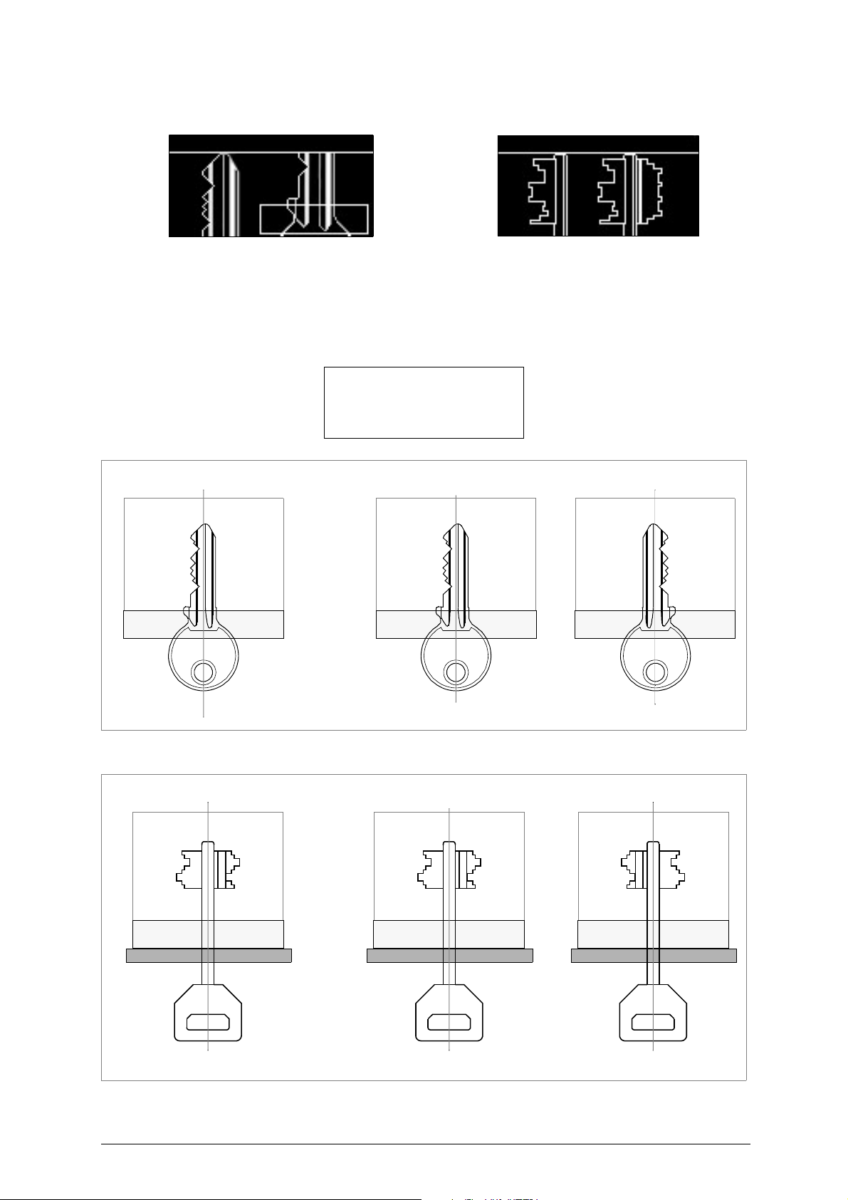
9) Confirm with ENTER, a few seconds later the display will show:
ATTENZIONE: the original key and the copy MUST BE FITTED FACING THE
SAME WAY, i.e. the cuts and profiles must be properly overlaid
(fig. 33 and fig. 34).
If not, the results of comparison will be negative or the following message
will appear:
To obtain a correct
match rotate
the key of 180°!
Fig. 33
Fig. 34
28 Copyright Silca 2017
Page 33
Optika Operating manual - English
L:2707
L:2419
left-hand bar (profile luminosity) left-hand bar (profile luminosity)
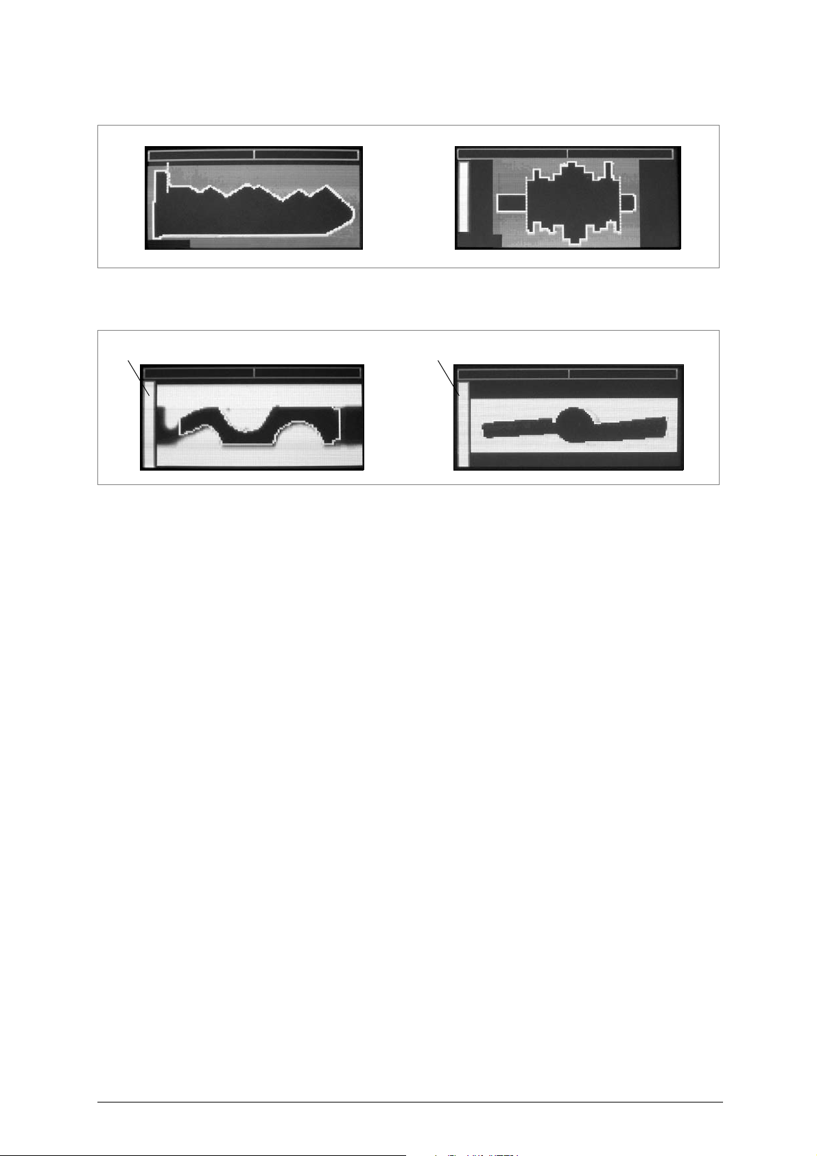
10)Remove the key, fit the new key to be compared; press ENTER, the display will show:
Fig. 35
11)
make sure the key is properly aligned (the top yellow bar must be just a vertical line)
.
12)Confirm with ENTER, a few seconds later the display will show:
13) Make sure the left-hand yellow bar should point upwards as much as possible. If not, follow the
instructions in ch.6.1.
14)Confirm with ENTER, a few seconds later the display will show the matching result (Examples):
Copyright Silca 2017 29
Page 34
Operating manual - English Optika
0.03 0.03
Confronto Standard
[0.20]
0.25 0.10
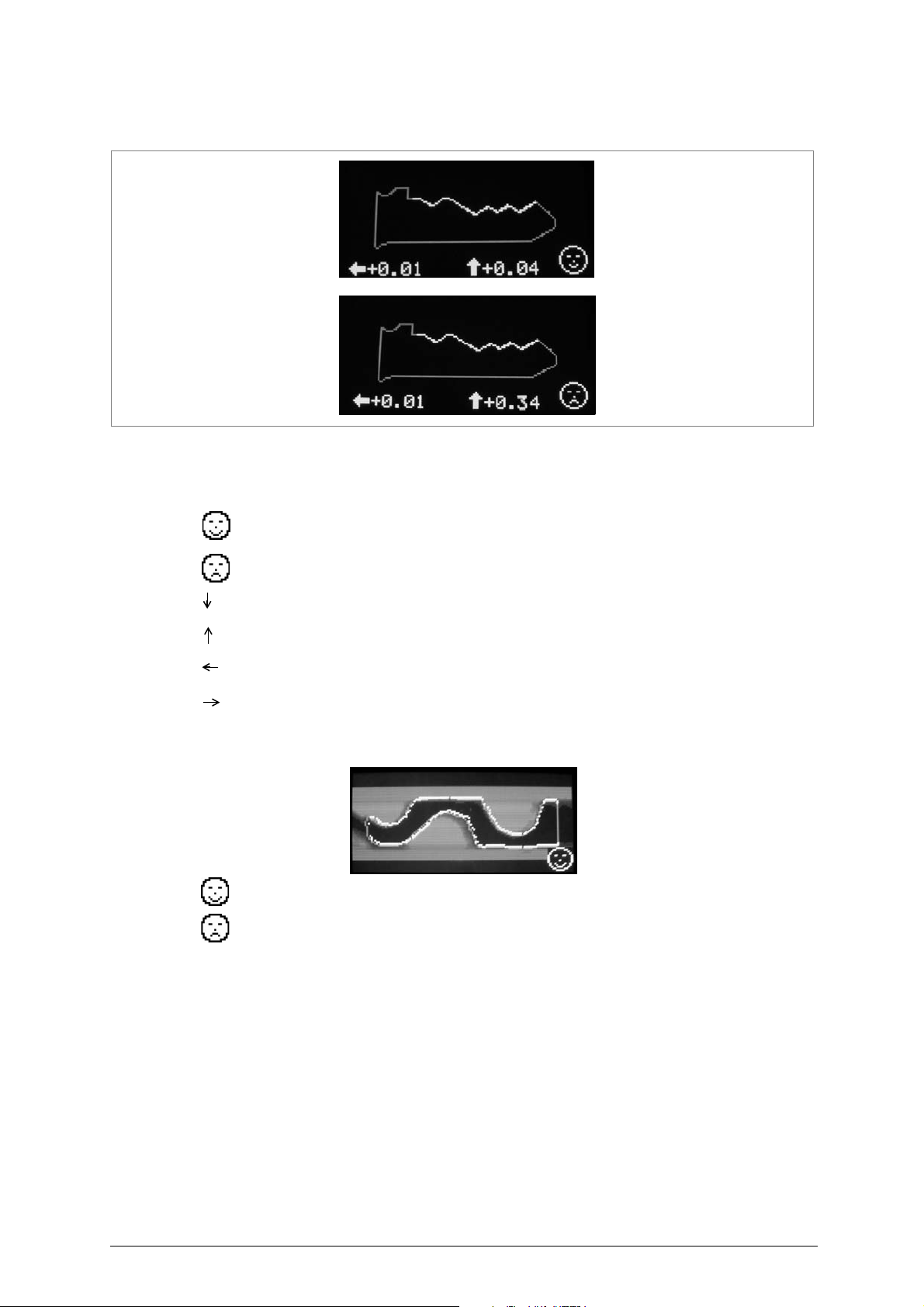
EXAMPLE FLAT KEYS
Fig. 36
The key shown in the results of comparison is always the copy.
Example: meaning of the symbols shown (arrows, values and faces).
smiling face = matching between keys is within the set parameters [Fine/Standard/By User] (*)
sad face = matching between keys is out of the set parameters [Fine/Standard/By User] (*)
0,03: cuts on the key compared with the cuts on the original key are deeper by 0,03 mm (0,001 2
inch)
0,25: cuts on the key compared with the cuts on the original key are higher by 0,25 mm (0,009 5
inch)
0.03:cuts on the key compared with the cuts on the original key are closer to the head by 0,03 mm
(0,0012 inch)
0.10:cuts on the key compared with the cuts on the original key are closer to the tip by 0,10 mm
(0,0038 inch)
Press ENTER, the display will show the profile:
Smiling face= indicates positive result of the profile comparison (*)
Sad face= indicates negative result of the profile comparison (*)
(*) Results referred to the parameters set in OPTIONS -> Search type (ch.6.4.5).
• Turn the right-hand knob (ENTER) to select side 1 or side 2.
30 Copyright Silca 2017
Page 35
Optika Operating manual - English
X
^
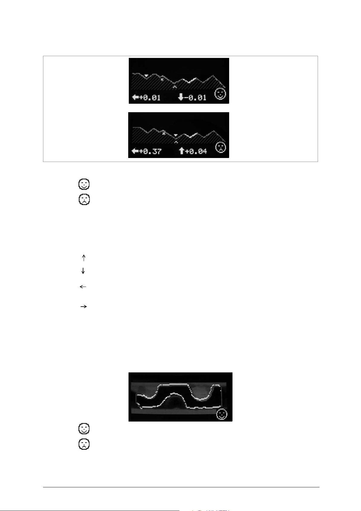
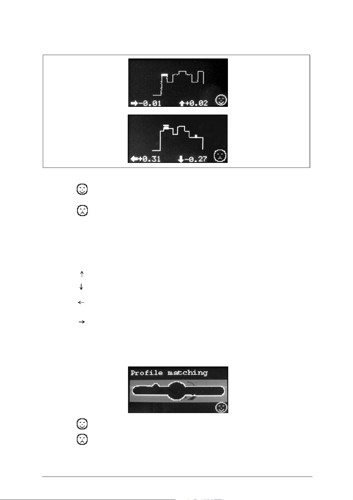
• Turn the left-hand knob (ESC) to access a detailed view of the individual teeth.
Fig. 37
Meaning of the symbols shown:
smiling face = matching between keys is within the set parameters [Fine/Standard/By User] (*)
sad face = matching between keys is out of the set parameters [Fine/Standard/By User] (*)
indicates the position where there is a difference in the number of teeth on the copied key and the
original key.
indicates the position where there is a difference in interaxis measurement or depth between the
copied key and the original key. The difference exceeds the tolerance set in the comparison parameters.
up arrow: indicates that the tooth on the copied key is higher than the one on the original key.
down arrow: indicates that the tooth on the copied key is lower than the one on the original key.
left-hand arrow: indicates that the selected interaxis on the copied key is more to the left than the
corresponding interaxis on the original key.
right-hand arrow: indicates that the selected interaxis on the copied key is more to the right than the
corresponding interaxis on the original key.
(**) A highlighted tilted section indicates that the same section on the original and copy keys has a
substantially different inclination angle.
• Press ESC to exit the detailed view and return to the results of comparison.
• Press ENTER, the display will show the profile:
Smiling face= indicates positive result of the profile comparison (*)
Sad face= indicates negative result of the profile comparison (*)
(*) Results referred to the parameters set in OPTIONS -> Search type (ch.6.4.5).
Copyright Silca 2017 31
Page 36

Operating manual - English Optika
MA TCHING TYPE
FLAT KEYS
spaces depths
+/- 15
(0,004")
+/- 30
(0,008")
+/- 10
(0,004")
+/- 20
(0,008")
+/- 35 +/- 35
Standards set by Silca
Cannot be edited
Standards set by Silca
Cannot be edited
Values set
or to be set by customer
Values table
(0,01mm)
FINE
STANDARD
BY USER
Note: choosing "Last reading" you start a new key matching function (eg. 2nd, 3rd, 4th... copy)
compared to the original key.
32 Copyright Silca 2017
Page 37
Optika Operating manual - English
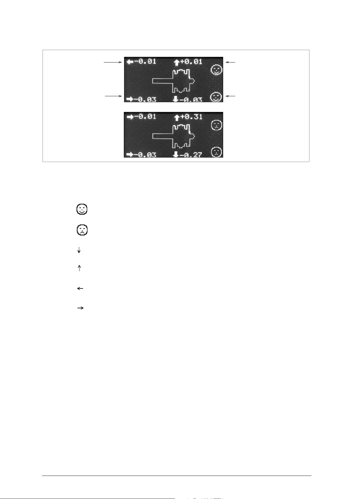
mean difference
for bit 1 depth
mean difference
for bit 2 depth
mean difference
for bit 1 interaxes
mean difference
for bit 2 interaxes
EXAMPLE BIT KEYS
Fig. 38
The key shown in the results of comparison is always the copy.
Example: meaning of the symbols shown (arrows, values and faces):
smiling face = matching between keys is within the set parameters [Fine/Standard/By User] (*)
sad face = matching between keys is out of the set parameters [Fine/Standard/By User] (*)
0,03: cuts on the key compared with the cuts on the original key are deeper by 0,03 mm
(0,0012inch)
0,31:cuts on the key compared with the cuts on the original key are higher by 0,31 mm (0,012 inch)
0.01:cuts on the key compared with the cuts on the original key are closer to the head by 0,01 mm
(0,0004 inch)
0.03:cuts on the key compared with the cuts on the original key are closer to the tip by 0,03 mm
(0,0012 inch)
• Turn the right-hand knob (ENTER) to select bit 1 or bit 2.
Copyright Silca 2017 33
Page 38
Operating manual - English Optika
X
-
• Turn the left-hand knob (ESC) to acce ss a detailed view of the individual teeth.
Fig. 39
Meaning of the symbols shown:
smiling face = matching between keys is within the set parameters [Fine/Standard/By User] (*)
sad face = matching between keys is out of the set parameters [Fine/Standard/By User] (*)
indicates the position where there is a difference in the number of teeth on the copied key and the
original key.
indicates the position where there is a difference in interaxis measurement or depth between the
copied key and the original key. The difference exceeds the tolerance set in the comparison parameters.
up arrow: indicates that the tooth on the copied key is higher than the one on the original key.
down arrow: indicates that the tooth on the copied key is lower than the one on the original key.
left-hand arrow: indicates that the selected interaxis on the copied key is more to the left than the
corresponding interaxis on the original key.
right-hand arrow: indicates that the selected interaxis on the copied key is more to the right than the
corresponding interaxis on the original key.
• Press ESC to exit the detailed view and return to the results of comparison.
• Press ENTER, the display will show the profile:
Smiling face= indicates positive result of the profile comparison (*)
Sad face= indicates negative result of the profile comparison (*)
(*) Results referred to the parameters set in OPTIONS -> Search type (ch.6.4.5).
34 Copyright Silca 2017
Page 39

Optika Operating manual - English
MATCHING TYPE
BIT KEYS
spaces depths
+/- 15
(0,006")
+/- 25
(0,010)
+/- 15
(0,006")
+/- 25
(0,010")
+/- 35 +/- 35
Standards set by Silca
Cannot be edited
Standards set by Silca
Cannot be edited
Values set
or to be set by customer
Values table
(0,01mm)
FINE
STANDARD
BY USER
Note: choosing "Last reading" you start a new key matching function (eg. 2nd, 3rd, 4th... copy)
compared to the original key.
6.2.2 MATCHING FROM "LAST READING"
Last Reading: in Optika’s memory there is always the last key read (regardless of whether the “Key
Search” or "Key matching" functions have been used). Therefore, if with an “original” key the “Key
Search” function had been used to find the corresponding reference, the copy made can be compared
by using “Last Reading”. The same applies if a number of copies made from the same “original” have
to be compared.
The “New Reading” function is used if the “original” key to be compared with the copy was not the
subject of a search or already compared.
ATTENTION: if “Last Reading” has been chosen and a type of key different from that in the memory (e.g. bit and
head stop) is fitted into the clamp, the display shows an anomaly message:
The key type select.
is not equal to
the original key
saved in memory
6.2.3 POSSIBLE ERRORS DURING "CUT MATCHING"
Cut comparison
is not possible!
Error ...
ERRORS 13 and 14:
It happens when there isn’t a correct alignment between the two keys in terms of spaces and depths
references. The possible causes could be: keys too different or not compatible.
ERRORS 15 and 16:
It happens when the device SW can’t calculate the averag e e rror o f spa ce s and dep ths o f the cutti ng s.
The possible causes could be: the keys are too different or the gap betwee n the two cuttings is too high.
The cuttings of
the inserted keys
cannot be matched!
repeat the operation
The message indicates that there is too much difference between the cuts and they cann ot be compared
within the limits defined by the program. Check that the two keys compared are similar and repeat the
procedure, if necessary. If the error remains try compari ng the original ke y and copied ke y turned 180°.
Copyright Silca 2017 35
Page 40

Operating manual - English Optika
The reading of the
bitting is wrong!
Reposition the key
and read again
This message indicates that the bitting of the key just read is not been correctly reconstructed and
therefore not available for comparison
Reposition the key and read again
.
.
No cut key
reading is
available for
comparison
This message appears only In “Comparison from last reading” when no bitting has been previously
saved for the comparison
Among possible causes:
no key is been actually read previously
-
-
the reconstruction of the bitting previously read is not correct
Repeat the comparison of the original and copy key as a “Comparison from new reading
.
.
.
”.
36 Copyright Silca 2017
Page 41
Optika Operating manual - English
Key copy
6.3 Key copy
Transmission to the IDEA electronic key-cutting machine
The Optika device is used to read then transmit the cuts of a bit key directly to the IDEA key-cutting
machine without the aid of a personal computer. Optika can be used as an altern ative to the optic reader
on the IDEA key-cutting machine, considerably reducing reading times.
ATTENTION:
• The cuts on a bit key read by Optika can be transmitted only to the IDEA
electronic key-cutting machine
• Before transmitting the key to be cut, make sure that:
- the key-cutting machine is live
- the key-cutting machine is not in motion
- OPTIKA and the key-cutting machine are con-
nected with a serial cable with adapter found
in the OPTIONAL KIT (fig. 40).
The cuts on the key to be read with Optika can be transmitted to the key-cutting machine in the
following ways:
6.3.1 Transmission from main menu
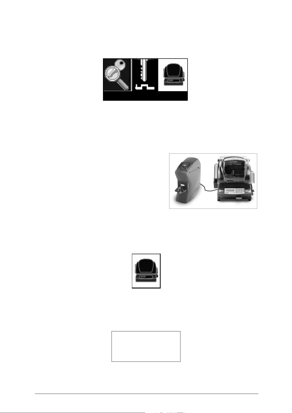
In the main menu select the “Key copy” icon:
1) press ENTER
2) select the type of bit key to be read
3) continue as with an ordinary search
In the place of the results of an ordinary search the material selection and number of pieces menu will appear.
MATERIAL:
Fig. 40
PIECES:
[TRANSMIT]
4) Turn the ENTER knob to select the field.
• the selected field will be highlighted in yellow.
Copyright Silca 2017 37
Page 42

Operating manual - English Optika
5) When the field “material” or ”pieces” is selected, turn the ESC knob to select the type of material of the
key blank to be used for the copy or to increase/decrease the number of pieces to be cut.
Default values are:
- Material = last material selected
- Pieces = 1
6) When the field “[Transmit]” is selected:
• press ESC to return to the main menu
• press ENTER to transmit the cuts to the key-cutting machine
Note: the job will be received by IDEA in the “PC queue” and any jobs already in the queue will be
deleted.
6.3.2 Transmission at the end of a search
When the results of a search for a bit key profile are shown, pre ss ENTER to access the following men u:
Menu selection:
Key copy
Ignore length
Profile info
Save profile
Search by key Manuf.
Search types
1) select the item “Key copy”
2) press ENTER.
3) the menu for entering material and number of pieces will appear
4) continue as described above
6.3.3 Possible errors during communication with the key-cutting machine
Key-cutting machine
in motion or unable
to receive data
from PC!
Appears during transmission, when the key-cutting machine is unable to receive data because it is on
start-up or in motion.
Operation not
possible with
connected machine
Appears if the key cutting machine connected to Optika is not the required one.
Major error
during transmission
Appears if during transmission there is an interruption in the serial connection or an error in the
transmission data.
38 Copyright Silca 2017
Page 43

Optika Operating manual - English
Options
6.4 Options
A series of operations, some merely consultations, by which users can familiarise with the device,
customise it to their needs and check its operation.
Press ENTER; the display will show:
Select option:
Device data
Language
User profiles
Keys in stock
Search type
Matching type
Hardware test
SW Upgrade
Service menu
6.4.1 MACHINE DATA
After confirmation of this function the display will show:
This is a read only display and the data shown cannot be edited.
6.4.2 LANGUAGE
After confirmation of this function the displa y will show a list of all the lang uages available on the device:
• Turn the ENTER knob (clockwise or anticlockwise) to select a language (field illuminated).
• Press the ENTER knob to view the selection asterisk.
Press ESC to go back to the previous menu; the language remains the one already in use.
Note: to make the chosen language operative, disconnect the device and wait 10 seconds before
starting up again.
Device data
Ser. 1122334455661
SW vers.:
DB vers.:
Keys read:
Italian
*English
French
German
Spanish
Copyright Silca 2017 39
Page 44

Operating manual - English Optika
6.4.3 USER PROFILES
The choices are:
Select function:
Modify profile
Delete profile
Keys in memory
- Turn the ENTER knob (clockwise or anticlockwise) to select the required function (field illuminated).
Press ENTER to confirm:
• Modify profile (user key):
After confirmation of this operation the display will show a list of the keys loaded into the database:
Select profile:
AAA
BBB
CCC
=>A
The left-hand side of the display will show a list of loaded keys and the right-hand side will show the
initial letter for the key to be searched for.
- Turn the ESC knob clockwise to change the initial letter for the search. On the display a list of the
keys loaded into the database will scroll.
- Turn the ENTER knob to scroll and select the key data to be edited.
After selecting a key press the ENTER knob and the display will show the following message:
Modify data:
Name: CCC
Manu: A
Hook: A
The same window will appear for entering data in the save profile function.
• Delete profile (user keys):
After confirmation of this function the display will show a list of the keys loaded into the database.
After selecting the profile, press the ENTER knob and the display will show the following message:
Select profile
AAA
BBB
CCC
=>A
- Turn the ENTER knob to scroll and select the profile (the article is highlighted). Press the ENTER
knob to confirm.
Delete profile?
<AAA>
No Yes
- Press the ESC knob to return to the previous menu without confirming deletion.
• To delete profile:
- turn the ENTER knob to select “Yes".
- press the ENTER knob to confirm deletion.
40 Copyright Silca 2017
Page 45
Optika Operating manual - English
• Keys in memory (user data):
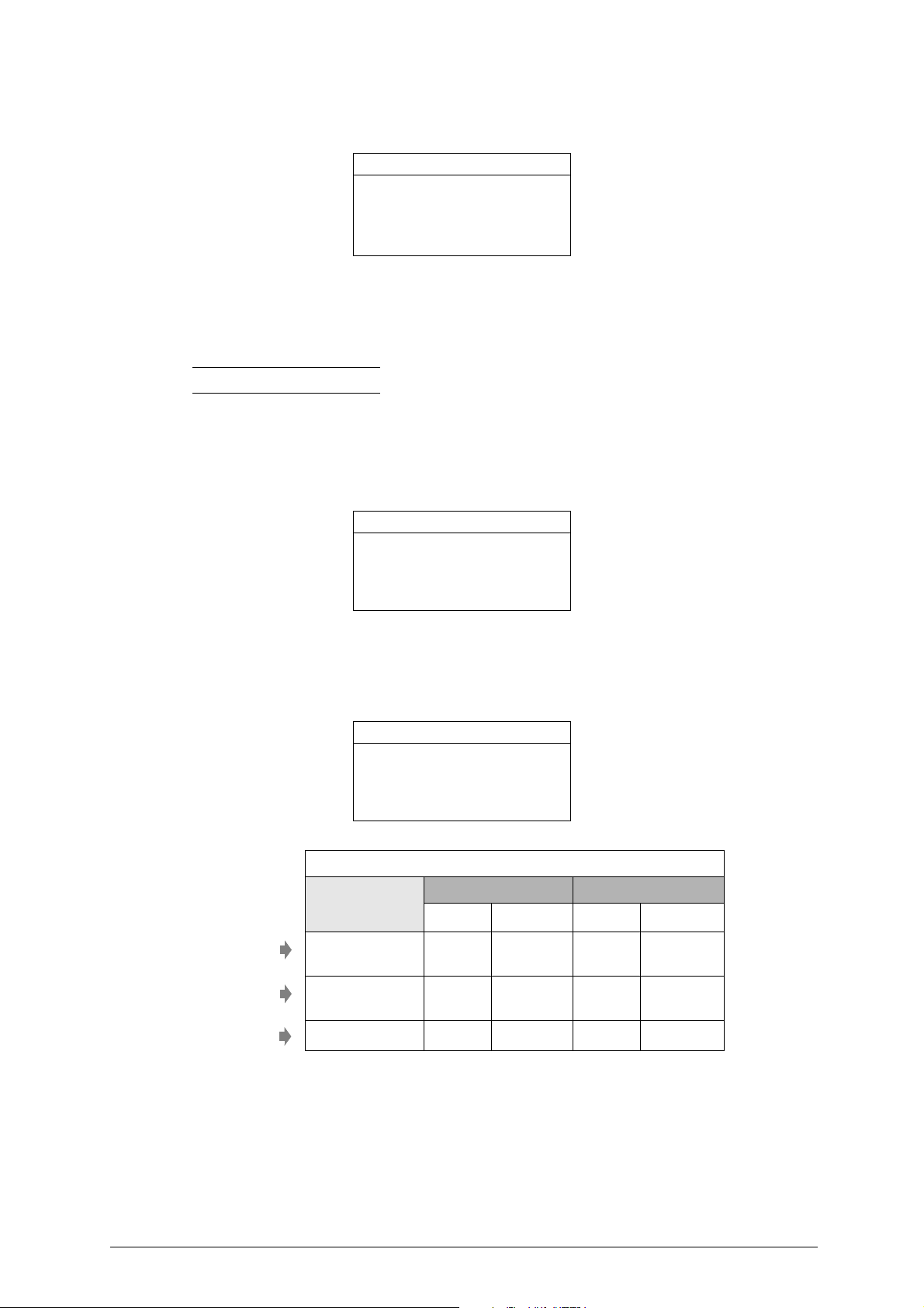
After confirmation of this function the display will show:
User key memory
Max profiles: 300
Used : 1
Free : 299
This is a read only display, the data shown cannot be edited.
- Press the ESC knob to exit.
6.4.4 KEYS IN STOCK
Note: this function will be available in the next software release.
6.4.5 SEARCH TYPE
This item is used to collect all parameters for co nfiguring the device with regard to sea rches in the profile
database and comparisons of cuts.
After confirmation of this function the display will show:
Select search type
*Fine
Standard
Extended
The possible settings (Fine - Standard - Extended) have been designed and define d by Silca to provide
fine, medium or extended compatibility. According to the set search parameter the resul t will show a few
or many key blanks.
6.4.6 MATCHING TYPE
Values table
Standards set by Silca
Cannot be edited
Standards set by Silca
Cannot be edited
Values set
or to be set by customer
FINE
STANDARD
BY USER
Select matching type:
*Fine
Standard
By User
MATCHING TYPE
FLAT KEYS BIT KEYS
(0,01mm)
spaces depths spaces depths
+/- 15
(0,004")
+/- 30
(0,008")
+/- 35 +/- 35 +/- 35 +/- 35
+/- 10
(0,004")
+/- 20
(0,008")
+/- 15
(0,006")
+/- 25
(0,010")
+/- 15
(0,006")
+/- 25
(0,010")
Copyright Silca 2017 41
Page 46
Operating manual - English Optika
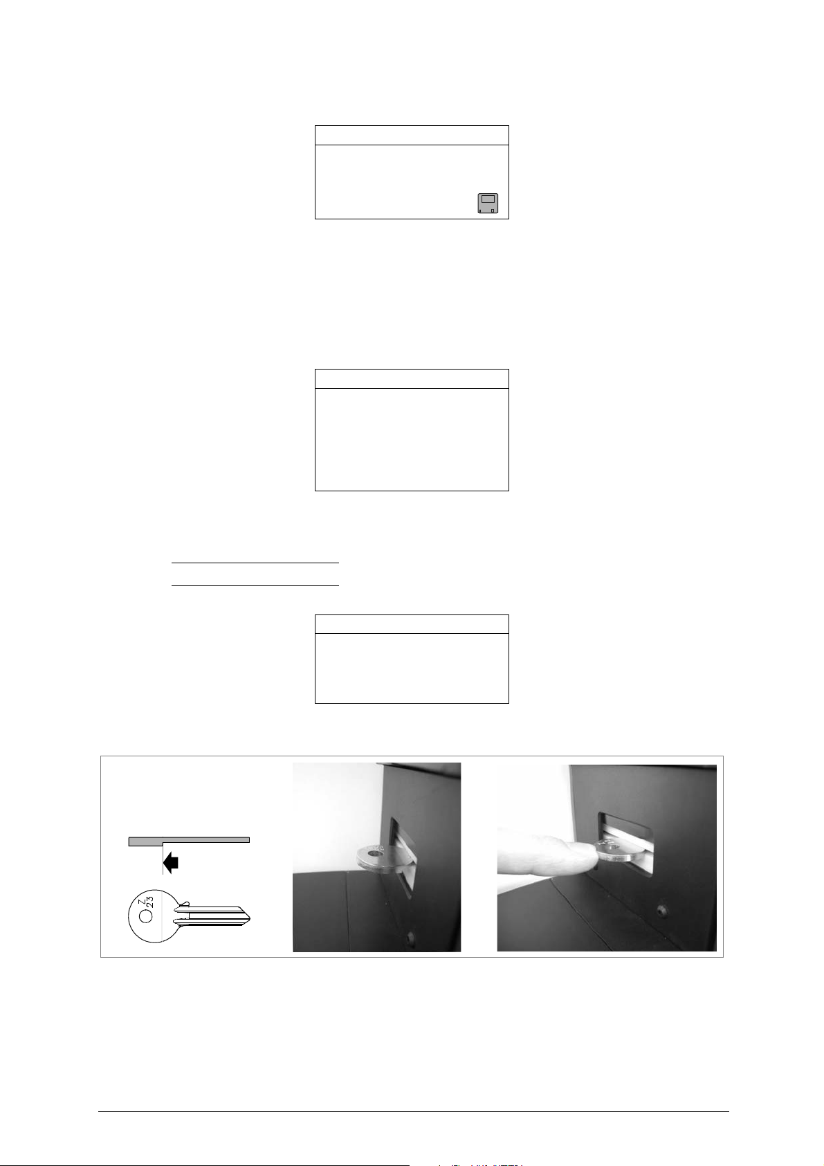
If the "BY USER" option is selected, press ENTER again to view the window:
Flat Bit
Space 40 Space 40
Depth 40 Depth 40
- turn the ENTER knob to go from one field to another.
- turn the ESC knob to edit a value (range 0-99).
- select the “Save” symbol (disk) and highlight by turning the ENTER knob. press the ENTER knob to
confirm the set values.
6.4.7 TEST HARDWARE
This paragraph presents all the tests necessary to check the optics and/or electronics of the device.
After confirmation of this function the display will show a list of all the tests available:
Select test:
Check adjustment
Check profile area
Check cuts area
Camera & led
Display
Keyboard
If there are problems the display will show the type of fault.
6.4.7.1 CHECK ADJUSTMENT
Note: we recommend that you perform this procedure at least once a year.
This function is used to check machine gauging.
1) Fit the Z23 template as if it were a flat key, making sure that the special stop is facing downwards
and butting against the illuminator (fig. 41).
Check adjustment
Insert template
Z23
Fig. 41
2) Standard key alignment procedure.
3) After confirmation the following display will appear (examples with purely indicative values):
42 Copyright Silca 2017
Page 47

Optika Operating manual - English
Example 1:
Detected values:
dL: 0.030001
dL: 0.050000
dT: 0.015000
Example 2:
Detected values:
dL: 0.030001
*dL: -8.350000
*dT: -2.150000
Example 1: satisfactory gauging
Example 2: the asterisk shows that gauging is not satisfactory (values out of range). Contact Silca’s
Technical Assistance Dept.
6.4.7.2 CHECK PROFILE AREA
Note: this operation is necessary when the image is out of focus or faulty and must be carried out
only on the advice of SILCA after-sales staff.
The operation is used to detect/gauge the area into which the profile could extend. The display will
show:
Check profile area
Attention
before proceding
see instruction manual
ENTER to continue
Check profile area
If this operation
is not performed
correctly it will cause
a malfunction
of the machine
Check profile area
Make sure there are
no keys or templates
in the clamp
ENTER to continue
Check profile area
Open and close
the clamp
- Flashing illuminators.
- Use lever (B) (fig. 7, page 7) to open and close the clamp when the white led is flashing; every flash
should correspond to one position. The positions must vary from maximum opening to closed,
including the intermediate positions.
Note: It is important that the clamp is on one position every time the led flashes, and is re-positioned
before the next flash.
The procedure can be repeated a number of times if you are not sure it has been carried out properly.
Copyright Silca 2017 43
Page 48

Operating manual - English Optika
- When the illuminators stop flashing the display will show:
Check profile area
Open and close
the clamp
Check completed
Press ESC to go back to the previous menus.
6.4.7.3 CHECK CUTS AREA
Note: this operation is necessary when the image is out of focus or faulty and must be carried out
only on the advice of SILCA after-sales staff.
The operation is used to gauge the clamp illumination area (position of key).
The display will show:
Check cuts area
Turn the clamp
right and left
- Turn the clamp (A) (fig. 7, pag e 7) right and left during flashing, making sure that every flash of the
red led corresponds to one position. The positions must vary from the far right to the far left, including
the intermediate positions.
ATTENTION: do not open the clamp during rotation.
Note: It is important that the clamp is on one position every time the led flashes, and is re-positioned
before the next flash.
The procedure can be repeated a number of times if you are not sure it has been carried out properly.
Press ESC to go back to the previous menus.
6.4.7.4 TELECAMERA and LED
Note: this function will be available in the next software release.
6.4.7.5 DISPLAY
Note: this function will be available in the next software release.
6.4.7.6 KEYBOARD
Note: this function will be available in the next software release.
Check cuts area
Turn the clamp
right and left
Check completed
44 Copyright Silca 2017
Page 49

Optika Operating manual - English
6.4.8 UPDATING OPTIKA INTERNAL PROGRAM
A) UPDATING/LOADING OPTIKA’s INTERNAL PROGRAM THROUGH A SERIAL CONNECTION
(40-50 minutes)
The updating of Optika’s internal program is allowed at these conditions:
a) the device is connected and switched on .
b) it is connected to a PC (through serial port and cable)
c) you have an updated Silca program:
- Silca Key Program
- Key Reader Program (CD provided with the machine)
The programs contain an on-line guide for the procedure.
B)
UPDATING/LOADING OPTIKA’s INTERNAL PROGRAM THROUGH A USB PEN-DRIVE
minutes
The updating of Optika’s internal program can be done with a USB pen-drive properly prepared with
Silca Key Program (Key Reader Program).
1) open the Silca Key Program (or the Key Reade r Progra m provided with Optika).
2) select the Optika device from the “Machine table” menu.
3) click on the “Advanced…” button.
4) select the “USB flash memory” tab and follow all the instructions there reported.
5) once the pen-drive has been prepared, select “SW Upgrade” from Optika’s “Options” menu.
)
(5-10
SW Upgrade
Insert pen-drive
and press ENTER
C)
LOADING OPTIKA’s INTERNAL PROGRAM FOLLOWING A STATE OF RECOVERY
(60 minutes
When Optika shows the following message at startup:
It Is possible to recover the internal program at these conditions:
a) the machine is running and the “RECOVERY” message is displayed.
b) it is connected to a PC (through serial port and cable)
d) you have an updated Silca progra m:
The programs contain an on-line guide for the procedure.
)
*** Optika Rescue ***
Restore
Turn off
- Silca Key Program
- Key Reader Program (CD provided with the machine)
ATTENTION: communication between a PC and the Optika USB (slave) will be available with a future software
release.
6.4.9 SERVICE MENU
Function protected by password.
Access is granted to Silca personnel only or to centres authorized by Silca to carry out work on this type
of device.
Copyright Silca 2017 45
Page 50
Operating manual - English Optika
P
7 MAINTENANCE
Note: all internal tests and repairs on this device should be performed only at Silca or Authorised
Centres.
ATTENTION: for repairs or replacement of parts for maintenance, the ‘CE’ mark is guaranteed only if original
spare parts provided by the manufacturer are used.
The OPTIKA device does not require special maintenance.
Replacement is simple and can be carried out by the operator.
CLEANING: your OPTIKA device should be kept in a relatively dust-free area; clean the surface
periodically with a vacuum cleaner.
ATTENTION: DO NOT USE COMPRESSED AIR!
Before starting any type of maintenance (checks or replacements) read the instructions below:
• Never carry out maintenance operations when the machine is on;
• Aalways disconnect the mains power supply;
• Before replacing parts read carefully all the instructions given.
• Use only original spare parts;
• Check that screws and nuts removed in order to replace parts are properly tightened.
• Work in an environment with temperature of 10° to 40° C and relative humidity of approx.
60%.
• The work bench should be: clean, free from anything not strictly necessary, and covered with
shock-proof material.
• Do not work with wet or greasy hands.
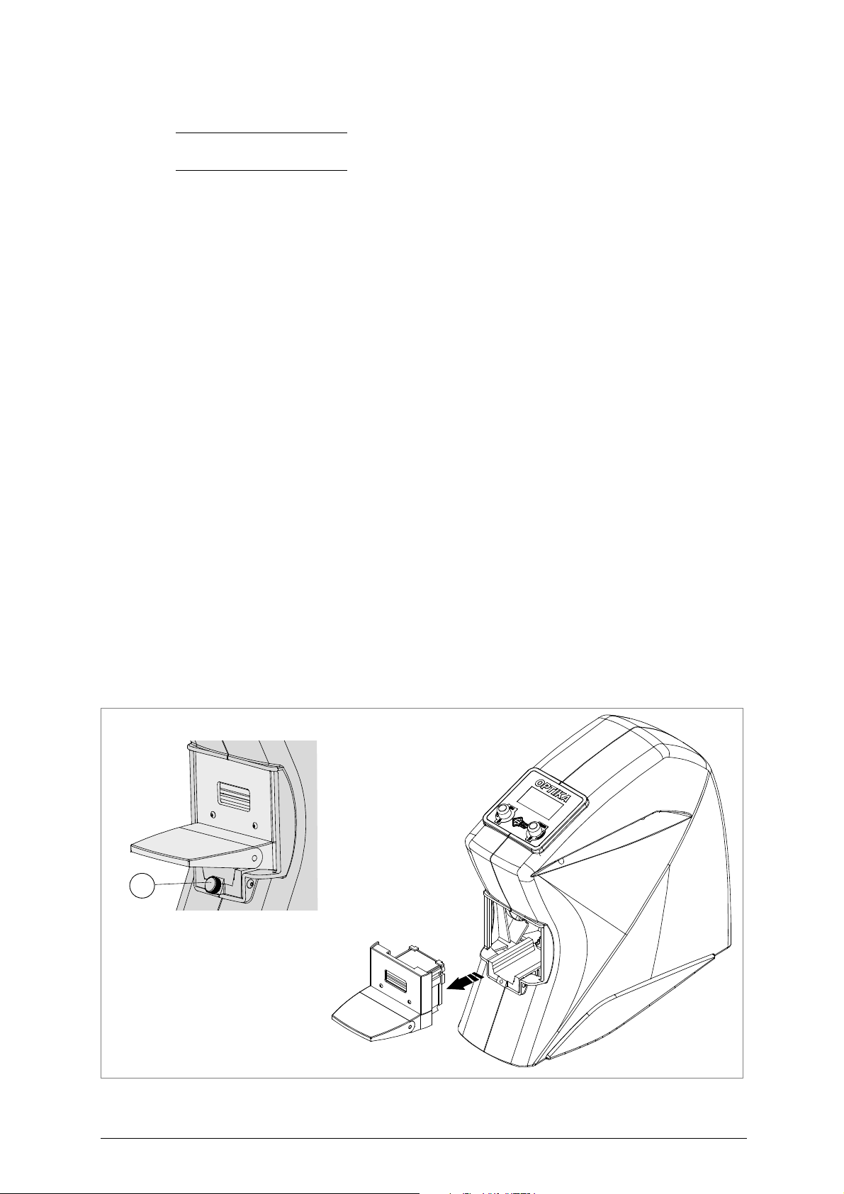
7.1 Clamp replacement
ATTENTION: we recommend carrying out this operation in a clean, dust-free environment.
1) Disconnect the machine power cable.
2) Completely unscrew the clamp fixing knob (P) (fig. 42).
3) Exert pressure with both hands on the clamp opening lever, remov e the clamp from its seat and place
on a clean surface.
ATTENTION: do not leave the device “open” (without the clamp) for too long ( eventually cover the device).
4) Fit the new clamp, taking care to push it all the way in.
5) Block the clamp against its limit switch and firmly tighten the knob (P).
Fig. 42
46 Copyright Silca 2017
Page 51
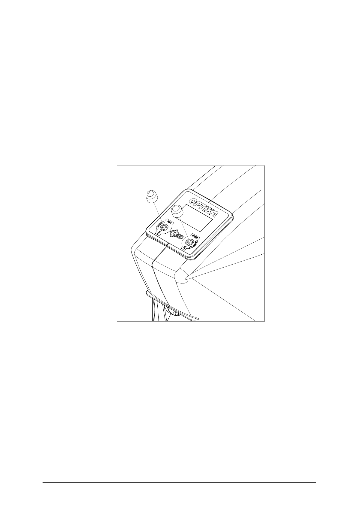
Optika Operating manual - English
7.2 Clamp cleaning
1) Disconnect the machine power cable.
2) Remove the clamp (see ch. 7.1, page 46).
3) Clean the key plate using the brush provided (see ch. 2, page 4). To simplify this operation turn the
clamp upside-down.
7.3 Check machine gauging
With device connected, fit the (Z 23) template into the clamp ( see ch.6.4.7.1, ch.6. 4.7.2, and ch.6.4 .7.3).
7.4 Knob replacement (ESC/ENTER)
1) Unplug the power supply unit
2) Pull the knob upwards (simply pressed in).
3) Fit the new knob, paying attention to the shaped part of the pin.
Fig. 43
Copyright Silca 2017 47
Page 52

Operating manual - English Optika
8 DISPOSAL
For correct disposal please refer to current standards.
INFORMATION FOR USERS OF PROFESSIONAL EQUIPMENT
From "Actuation of Directive 2012/19/EU regard ing Waste Electrical and Electronic Equipment
(WEEE
)"
The symbol of a crossed waste bin found on equipment or its packing indicates that at the end of the
product’s useful life it must be collected separately from other waste so that it can be properly treated
and recycled.
In particular, separate collection of this profession al equip ment when n o longer in use is org anised and
managed:
a) directly by the user when the equipment was placed on the market before 31 December 2010 and the
user personally decides to eliminate it without replacing it with new equivalent equipment designed for
the same use;
b) by the manufacturer, that is to say the subject which was the first to introduce and market new equip-
ment that replaces previous equipment, when the user decides to eliminate equipment placed on the
market before 31 December 2010 at the end of its useful life and replace it with an equivalent product
designed for the same use. In this latter case the user may ask the manufacturer to collect the existing
equipment;
c) by the manufacturer, that is to say the subject which was the first to introduce and market new equip-
ment that replaces previous equipment, if it was placed on the market after 31 December 2010;
Suitable separate collection for th e purpose of forwardi ng discard ed equi pment for re cycling, treatmen t
or disposal in an environmentally friendly way helps to avoid possible negative effects on the
environment and human health and encourage s re-use and /or recycling o f the m aterials makin g up the
equipment.
The sanctions currently provided for by law shal l apply to users who dispose of products in unauthorised
ways.
48 Copyright Silca 2017
Page 53

Optika Operating manual - English
9 AFTER-SALES SERVICE
Silca provides full service to purchasers of the OPTIKA device.
To ensure complete safety for the operat or and machine, any j ob not specified in this manual should be
carried out by the manufacturer or in a Silca authorized Service Centre.
On the back cover of this manual is a list of the manufacturer’s addresses; listed below are the
addresses of Silca authorized Service Centres.
9.1 How to request service
The guarantee attached to the OPTIKA device ensures free repairs or replacements of faulty parts
within 24 months of purchase. All other service calls must be arranged by the customer with Silca or
with a Silca authorized Service Centre.
Copyright Silca 2017 49
Page 54

Page 55

Operating manual - English OPTIKA
Appendix 1 - ELECTRICAL DIAGRAMS
The following pages contain the electrical diagrams for the OPTIKA device described in this manual
.
Copyright Silca 2017 Appendix - I
Page 56

Page 57
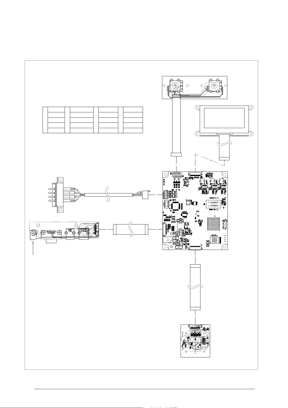
Operating manual - English OPTIKA
Scheda I/O
Scheda Madre
Mother Board
Scheda obiettivo
Scheda Encoder
Display
1
NERO
2
AZZURRO
3
GIALLO
4
ROSSO
BLACK LIGHT BLUE YELLOW RED
SCHWARZ BLAU GELB ROT
NOIR AZUR JEUNE ROUGE
NEGRO AZUL AMARILLO ROJO
1
2
3
4
Presa alimentazione
Power supply socket
Steckdose Speisegerät
Prise alimentation
Toma de
alimentación
U1
J
2
U21
L9
L10
R
1
F1
P2
P1
U1 J1
1
Inlets/Outlets Board
Mutterkarte
Carte mère
Ficha madre
Karte Eingang/Ausgand
Fiche Entrées/Sorties
Ficha Entradas/Salidas
Encoder board
Encoder Karte
Fiche Encoder
Ficha Encoder
Objective board
Objektiv-Karte
Fiche objectif
Ficha objetivo
C
a
b
l
a
g
g
i
o
i
l
l
u
m
i
n
a
t
o
r
i
I
l
l
u
m
i
n
a
t
o
r
s
w
i
r
i
g
V
e
r
k
a
b
e
l
u
n
g
I
l
l
u
m
i
n
a
t
o
r
e
m
C
â
b
l
a
g
e
i
l
l
u
m
i
n
a
t
e
u
r
s
C
a
b
l
e
a
d
o
i
l
u
m
i
n
a
d
o
r
e
s
OPTIKA
ELECTRICAL DIAGRAMS
Copyright Silca 2017 Appendix - III
Page 58
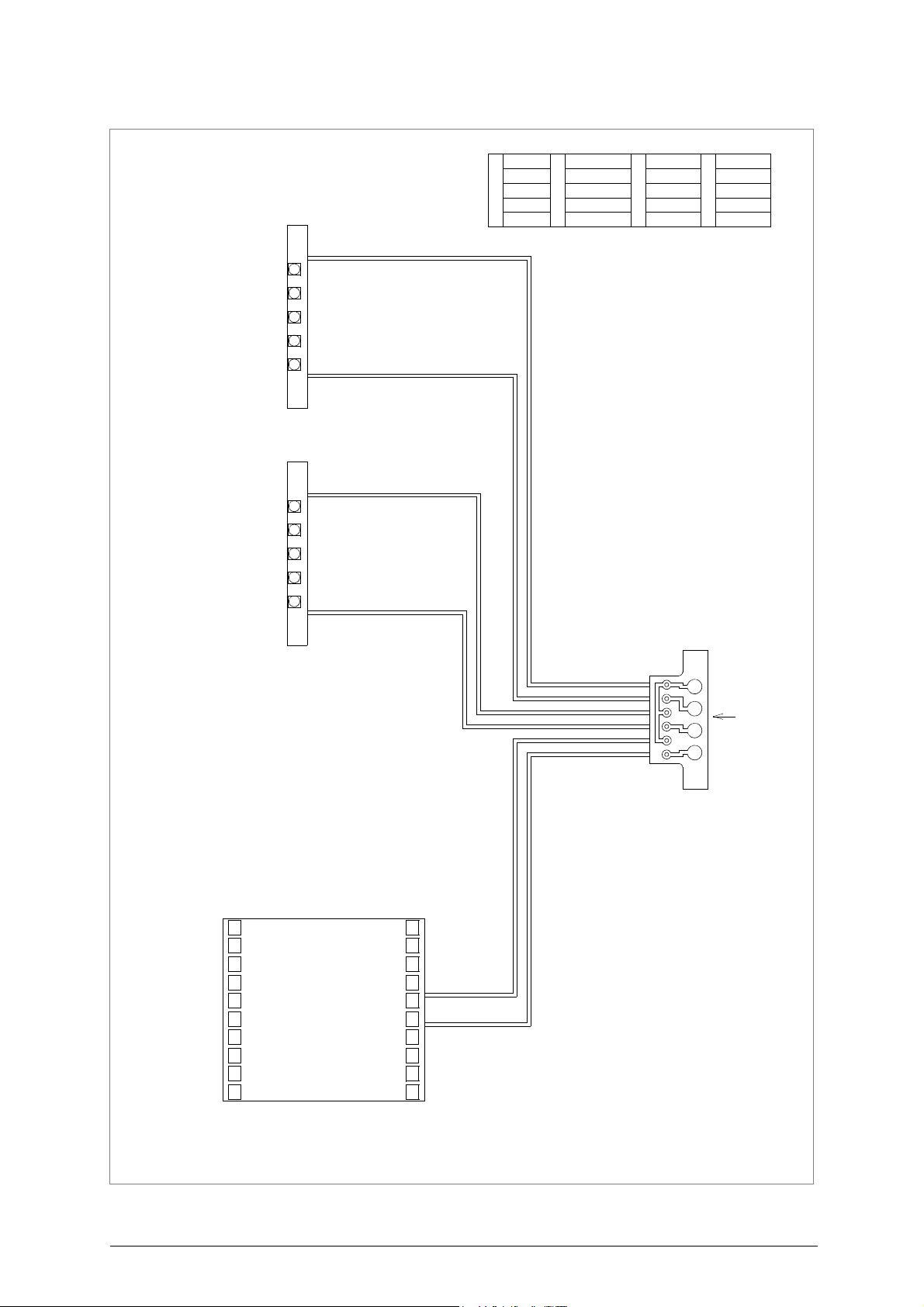
Operating manual - English OPTIKA
Illuminatore superiore
Scheda uscita illuminatori
Scheda piano luminoso
1
1
1
2
3
4
D
a
c
a
b
l
a
g
g
i
o
i
l
l
u
m
i
n
a
t
o
r
i
1
NERO
2
AZZURRO
3
GIALLO
4
ROSSO
BLACK LIGHT BLUE YELLOW RED
SCHWARZ BLAU GELB ROT
NOIR AZUR JEUNE ROUGE
NEGRO AZUL AMARILLO ROJO
Illuminators outlet board
Illuminatoren Ausgang-Karte
Fiche sortie illuminateurs
Ficha salida iluminadores
F
r
o
m
i
l
l
u
m
i
n
a
t
o
r
s
w
i
r
i
g
V
o
n
V
e
r
k
a
b
e
l
u
n
g
I
l
l
u
m
i
n
a
t
o
r
e
m
D
e
c
â
b
l
a
g
e
i
l
l
u
m
i
n
a
t
e
u
r
s
d
e
c
a
b
l
e
a
d
o
i
l
u
m
i
n
a
d
o
r
e
s
Upper illuminator
Oberer Illuminator
Illuminateur supérieur
Iluminador superior
Illuminatore inferiore
Lower illuminator
Unterer Illuminator
Illuminateur inférieur
Iluminador inferior
Bright plan board
Karte leuchtender Plan
Fiche étage lumineux
Ficha plan luminoso
IV - Appendix Copyright Silca 2017
Page 59
VITTORIO VENETO 04/01/2010
CE DECLARATION OF MACHINE COMPLIANCE
SILCA S.p.A. - VIA PODGORA 20 ( Z.I.)
31029 VITTORIO VENETO (TV) - (ITALY)
TEL. 0438 9136 - FAX. 0438 913800
Declares under its own responsibility that the Reader model
OPTIKA
complies with the requirements of the following European Directives:
European Union DIRECTIVE 2004/108/CE
and with the EN 55022 - EN 55024
EN 61000-3-2 - EN 61000-3-3 Standards
General Manager Basic Production Center
(Electromagnetic Compatibility)
Page 60

SILCA S.p.A.
Via Podgora, 20 (Z.I.)
31029 VITTORIO VENETO (TV)
Phone: +39 0438 9136
Fax +39 0438 913800
E-mail: [email protected]
www.silca.biz
United Kingdom
SILCA Ltd.
Unit 6 Lloyds Court - Manor Royal
CRAWLEY RH10 9QU
Phone: +44 1293 531134
Fax +44 1293 531108
E-mail: [email protected]
www.silcaltd.co.uk
France
SILCA S.A.S.
12, Rue de Rouen
Z.I. de Limay - Porcheville
78440 PORCHEVILLE
Phone: +33 1 30983500
Fax +33 1 30983501
E-mail: [email protected]
www.silca.fr
Germany
SILCA GmbH
Siemensstrasse, 33
42551 VELBERT
Phone: +49 2051 2710
Fax +49 2051 271172
E-mail: [email protected]
www.silca.de
India
MINDA SILCA Engineering Ltd.
Plot no.37, Toy City,
GREATER NOIDA (U.P.) - 201308
Phone: +91 9871397630/31
Fax: +91 120 2351301
E-mail: [email protected]
www.mindasilca.in
North America
U.S.A., Canada, Caribbean Islands
KABA Ilco Corp.
400 Jeffreys Road
Rocky Mount, NC 27804 USA
Phone: 1 800 334 1381 / 1 252 446 3321
Fax: 1 252 446 4702
E-mail: [email protected]
www.ilco.us
Central America
Mexico, Guatemala, Belize, El Salvador,
Honduras, Nicaragua, Costa Rica, Panama
Corporación Cerraiera Alba S.A. de C.V.
Prolongaci
Col.Los reyes, Tultitlán, Estado de México C.P. 54915
ón avenida independencia 14, Bodega 5,
E-mail: [email protected]
Kaba Mexico
Phone: 01 55 5366 7200
www.kabamexico.com
Spain
SILCA KEY SYSTEMS S.A.
C/Santander 73A
08020 BARCELONA
Phone: +34 93 4981400
Fax +34 93 2788004
E-mail: [email protected]
www.silca.es
Netherlands
H. CILLEKENS B.V.
Metaalweg, 4
6045 JB ROERMOND
Phone: +31 475 325147
Fax +31 475 323640
E-mail: [email protected]
www.hcillekens.nl
Brazil
KABA DO BRASIL Ltda
Rua Guilherme Asbahr Neto, 510
São Paulo, SP 04646-001
Phone: +55 11 55454520 / 29
E-mail: [email protected]
www.silcachaves.com.br
Colombia
SILCA SOUTH AMERICA S.A.
Km 1.5 Via Briceño-Zipaquira
Parque Ind. Trafalgar Bodega 3
Tocancipa-Cundinamarca
Phone: +57 1 7366480
Fax +57 1 7366490
www.fl exonsilca.co
 Loading...