

Page 1
Operating Manual
Original Instructions
D443308XA
vers. 1.0
EN
Page 2

(c) 2014 SILCA S.p.a. - Vittorio Veneto
This manual has been drawn up by SILCA S.p.a.
All rights reserved. No part of this publication can be reproduced or circulated by any means whatsoever (photocopies, microfi lm or other)
without the consent of SILCA S.p.A.
Edition: January 2014
Printed at Vittorio Veneto
da SILCA S.p.a.
via Podgora, 20 (Z.I.)
31029 VITTORIO VENETO (TV) - Italy
The Manufacturer declines any responsibility for possible inaccuracies in this document due to printing or transcription errors. The Manufacturer reserves the right to alter the information without prior notice, except when they affect safety. This document or any of its parts cannot be
copied, altered or reproduced without written authorization from the Manufacturer. Keep the manual and look after it for the entire life cycle of the
machine.
The information has been drawn up by the manufacturer in his own language (Italian) to provide users with the necessary indications to use the
key-cutting machine independently, economically and safely.
IMPORTANT NOTE: in compliance with current regulations relating to industrial property, we hereby state that the trade-marks or trade names
mentioned in our documentation are the exclusive property of authorized manufacturers of locks and users.
Said trade-marks or trade names are nominated only for the purposes of information so that any lock for which our keys are made can be rapidly
identifi ed.
Page 3

INDEX
USE OF THE MANUAL .......................................................................................................................1
TERMINOLOGY .................................................................................................................................2
1 MACHINE DESCRIPTION ....................................................................................................................5
1.1 WORKING PARTS ......................................................................................................................6
1.2 ACCESSORIES PROVIDED .....................................................................................................7
1.3 TECHNICAL DATA .....................................................................................................................7
1.4 ELECTRIC DIAGRAM ............................................................................................................8
2 HANDLING ...........................................................................................................................................9
2.1 PACKING ....................................................................................................................................9
2.2 TRANSPORT ..............................................................................................................................9
2.3 UNPACKING ...............................................................................................................................9
2.4 HANDLING THE MACHINE ........................................................................................................9
3 MACHINE INSTALLATION AND PREPARATION ..............................................................................10
3.1 CHECKING FOR DAMAGE ......................................................................................................10
3.2 ENVIRONMENTAL CONDITIONS ............................................................................................10
3.3 POSITIONING ..........................................................................................................................10
3.4 SAFETY DEVICES ...................................................................................................................10
3.5 WORK STATION DESCRIPTION .............................................................................................11
3.6 STARTING THE KEY-CUTTING MACHINE .............................................................................12
3.6.1 STARTING THE MOTOR .....................................................................................................12
3.6.2 CUTTER MOTOR ON WARNING LIGHT .............................................................................12
3.6.3 LED LAMP ...........................................................................................................................12
4 MACHINE CALIBRATION AND REGULATION ..................................................................................13
4.1 FITTING AND REMOVING TOOLS ..........................................................................................13
4.2 MICROMETER GAUGE ...........................................................................................................14
4.3 CALIBRATION / TOOL ALIGNMENT ........................................................................................15
4.4 TRACER POINT SPRING........................................................................................................16
4.5 CLAMPS ..................................................................................................................................17
5 CUTTING ............................................................................................................................................18
5.1 FITTING KEYS .........................................................................................................................18
5.2 KEY STOP ................................................................................................................................18
5.3 CUTTING DIMPLE KEYS .........................................................................................................19
5.3.1 BACK CUTS .........................................................................................................................19
5.4 CUTTING LASER TYPE KEYS ................................................................................................20
5.5 CUTTING LASER KEYS WITH NARROW STEMS (MERCEDES) .........................................21
5.6 CUTTING FICHET TYPE KEYS (H PROFILE) WITH OPTIONAL ADAPTER “F” ....................21
6 MAINTENANCE ..................................................................................................................................22
6.1 TIGHTENING AND REPLACING THE BELT ............................................................................22
6.2 REMOVING THE UPPER FRONT UNIT ..................................................................................23
6.3 REPLACING THE ROLLBAR ...................................................................................................23
6.4 REPLACING THE TRANSPARENT SAFETY SHIELD .............................................................24
Page 4

6.5 REPLACING THE LAMP ..........................................................................................................24
6.6 ADJUSTING/REPLACING THE VERTICAL CARRIAGE SPRING ...........................................25
6.7 CHECKING AND REPLACING FUSES ....................................................................................26
6.8 REPLACING THE CALIBRATION KEY PAD ELECTRONIC CIRCUIT BOARD.......................27
6.9 REPLACING THE CONDENSER .............................................................................................27
6.10 REPLACING THE MOTOR .......................................................................................................28
6.1 1 REPLACING THE TRANSFORMER ........................................................................................28
6.12 REPLACING SWITCHES: MASTER AND MOTOR ON ...........................................................29
6.13 ALIGNING/CALIBRA TING THE CLAMP ...................................................................................30
6.13.1 CONTROL ALIGNMENT LEFT-HAND STATIONARY JAWS ...............................................30
6.14 REPLACING THE JAWS ..........................................................................................................31
6.14.1 REPLACING THE FIXED JAWS ..........................................................................................31
6.14.2 REPLACING MOBILE JAW ON LEFT-HAND CLAMP ........................................................32
6.14.3 REPLACING MOBILE JAW ON RIGHT-HAND CLAMP ......................................................32
7 DISPOSAL .........................................................................................................................................33
8 AFTER-SALES SERVICE ..................................................................................................................34
8.1 HOW TO APPL Y FOR AFTER-SALES SERVICE ...................................................................34
Page 5
Operating manual Matrix ONE
USE OF THE MANUAL
This manual has been drawn up by the Manufacturer and is an integral part of the machine literature.
The manual gives information it is obligatory for the operator to know and which makes it possible to use the
machine safely.
User’s Manual
This user’s manual is provided because it is essential for proper use and maintenance of the machine.
The manual must be kept carefully throughout the life of the machine, including the decommissioning stage. Keep
in a dry place close to the machine where it is always to hand for the operator .
IT IS OBLIGATORY to read the manual carefully before using the machine.
• Readers’ characteristics
This manual must be read and its contents acquired by those who will use it .
The MATRIX ONE key-cutting machine is designed for professional use by adults of either gender in full
possession of their physical, sensorial or mental capacities.
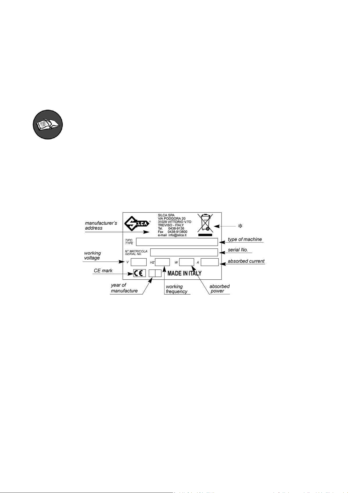
• Manufacturer’s ID
MATRIX ONE has an ID plate located on the back of the machine, showing the serial number.
Fig. 1
(*) See chap. 7 DISPOSAL.
• How to apply for after-sales service
Silca provides purchasers of MATRIX-ONE with After-Sales Service.
For the total safety of the operator and machine, any operation not described in the manual must be carried out
by the manufacturer or in the special Service Centres recommended by Silca.
At the end of the manual there is a list of manufacturers’ and authorized Service Centre addresses.
The warranty card attached to the machine covers free repairs or replacement of faulty parts for 24 months from
the date of purchase*. All operations must be agreed by the user with Silca or the Service Centre.
* Damage caused by negligence or wrong use of the machine by the user will null the warranty.
Copyright Silca 2014
1
Page 6
Operating manual Matrix ONE
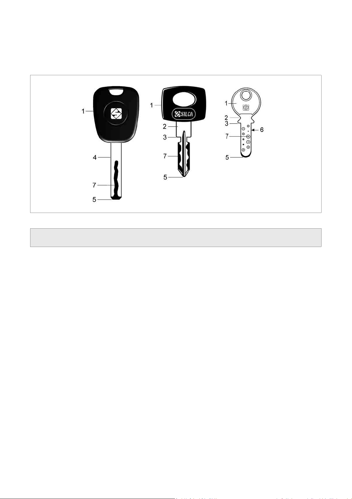
TERMINOLOGY
For those inexperienced in the subject of keys and key cutting, below is an illustration of the most frequently used
terms:
1) Head
2) Neck
3) Stop
4) Stem
Fig. 2
5) Tip
6) Back
7) Cuts
2
Copyright Silca 2014
Page 7
Operating manual Matrix ONE
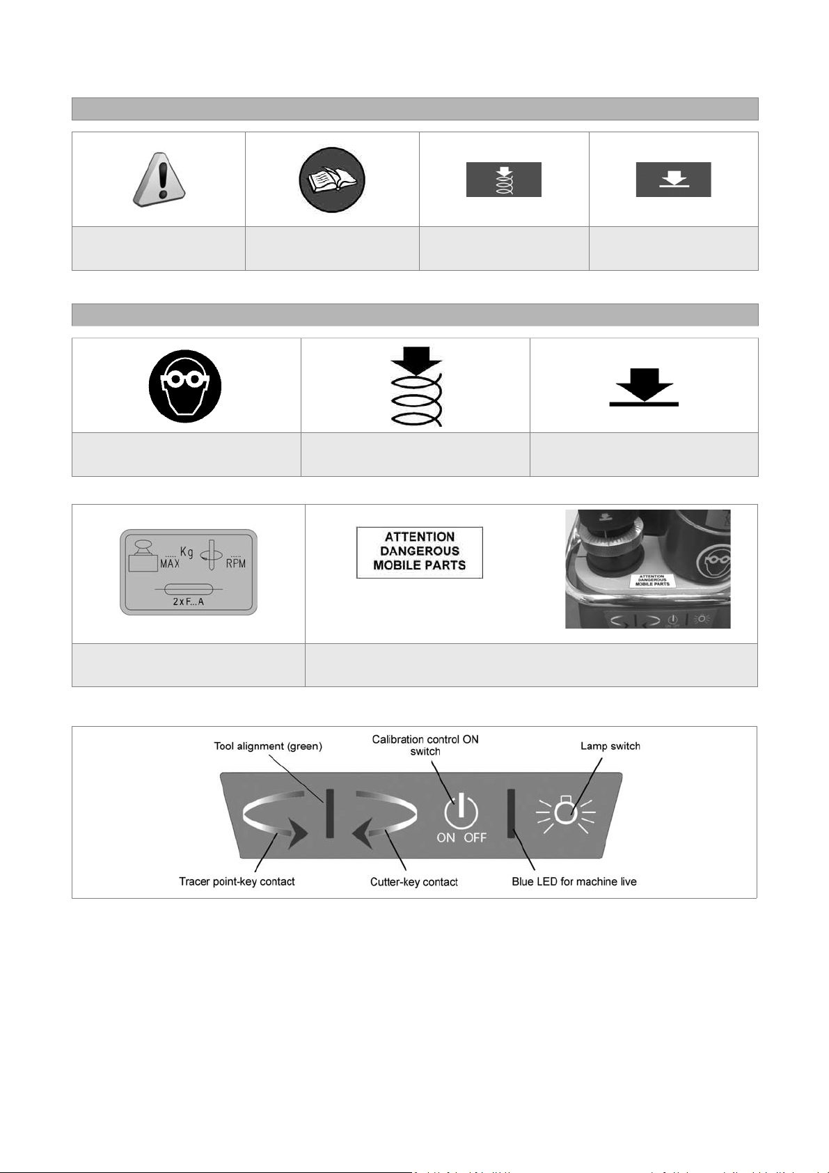
GRAPHICS IN THE USER’S MANUAL
Pay attention
Obligation to read
the manual
Activation of
tracer point spring
GRAPHICS ON THE MATRIX-ONE KEY-CUTTING MACHINE
Obligatory use of
safety goggles
Tracer point spring
ON
(chap. 1.2)
place the adhesive label
in the way illustrated.
Deactivation of
tracer point spring
Tracer point spring
OFF
Adhesive label
Mass - RPM - Fusibles
Adhesive label
“DANGEROUS MOBILE PARTS”
Fig. 3
Copyright Silca 2014
3
Page 8

Operating manual Matrix ONE
GENERAL WARNINGS
MATRIX ONE is designed to the principles of European Standards (CE).
Right from the design stage solutions have been adopted to eliminate hazards for the operator in all the stages
of use: handling, regulation, use and maintenance.
The materials used in manufacture and the components employed in using MA TRIX-ONE are not dangerous and
ensure that the machine complies to current standards.
Silca S.p.A. has also experimented and applied numerous technical solutions that allow the key-cutting machine
to optimize the quality of the cut keys.
To guarantee maintaining these results over time, please follow the instructions below:
• Observe the procedures described in this manual;
• Always use Original Silca Tools as they are designed to make the best of MATRIX-ONE and provide
quality key-cutting;
• Use Silca key blanks, made with top quality materials;
• Have the key-cutting machine checked periodically by an authorized Silca After-Sales Service Centre
(list at the end of this manual).
• Always use Silca Original Spare Parts. Beware of imitations!
NORMAL USE
MATRIX-ONE is a key-cutting machine and must be installed and used according to the rules and specifi cations
established by the manufacturer.
The MATRIX ONE key-cutting machine is designed for use on business or industrial premises (e.g. hardware
shops,
key cutting centres, etc...).
Any other use different from that indicated in this manual will cause the forfeiture of all customers’ rights to make
claims on Silca S.p.A. and may be an unknown source of hazard for the operator or third parties.
ATTENTION: negligent use or failure by the operator to observe the instructions in this manual
are not covered by the warranty and the manufacturer declines any responsibility in such
cases.
RESIDUAL RISKS
On the MA TRIX-ONE key-cutting machine there is a residual risk of injury
in the cutter spindle area (cutter rotating) if the vertical axis for laser cuts
is blocked.
Furthermore, the MATRIX-ONE key-cutting machine has residual risks
when gaining access to parts in motion (not fully protected) and the risk
of chippings fl ying into the air during the key copying process.
These residual risks in the product are reported in special warnings
(“ATTENTION DANGEROUS MOBILE PARTS”) and involve the
obligatory use of personal protective devices (GOGGLES).
Fig. 4
SAFETY REGULATIONS
• Always disconnect the machine when it is not in use or when performing maintenance operations.
• Check the electrical wiring periodically; replace any wires that show signs of wear.
• Always work with dry hands free of grease or oil.
• Never pull hard on the power lead and make sure it does not come into contract with oil, sharp objects
or heat. Never remove the earth wire from the plug. Make sure the earth wire connection is sound.
• Do not use the machine in dangerous environments (wet or damp).
• All visitors, especially children, must stay at a safe distance from the machine and must never come
into contact with the electric wiring.
• Place the adhesive label provided “DANGEROUS MOBILE P ARTS” as shown in chap.3.3 POSITIONING.
4
Copyright Silca 2014
Page 9
Operating manual Matrix ONE
1 MACHINE DESCRIPTION
The MATRIX-ONE key-cutting machine gives excellent technical performance of great precision.
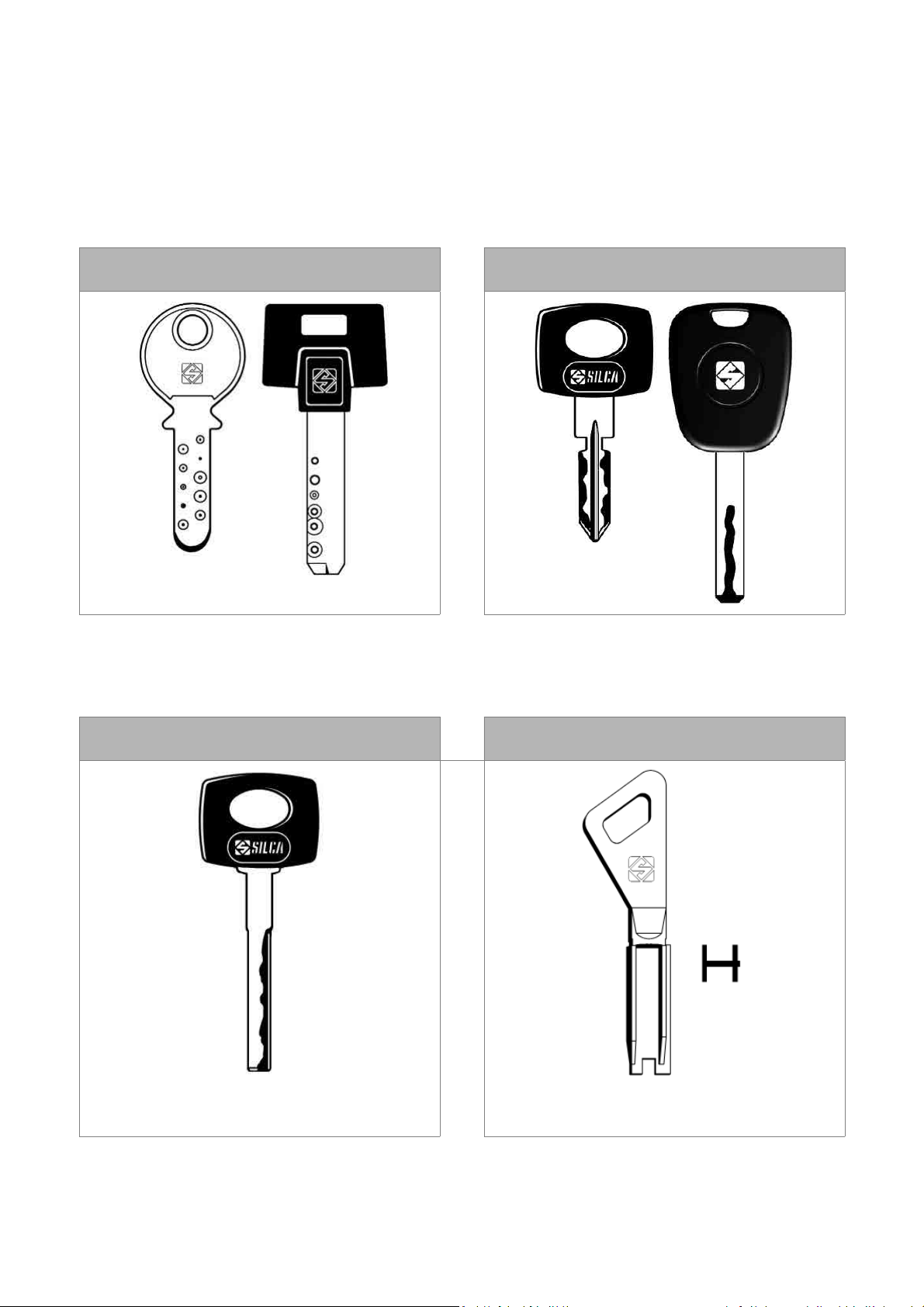
The standard clamp on MATRIX-ONE is used to cut some of the following types of keys:
• keys with fl at dimple cuts
• keys with laser type cuts
KEYS WITH DIMPLE CUTS KEYS WITH LASER TYPE CUTS
LASER KEYS WITH A
NARROW STEM (MERCEDES)
with OPTIONAL adapter “M”
(see chap.5.5)
OPTIONAL
FICHET type KEYS
(H profi le)
with OPTIONAL adapter “F”
(see chap.5.6)
Copyright Silca 2014
5
Page 10
Operating manual Matrix ONE
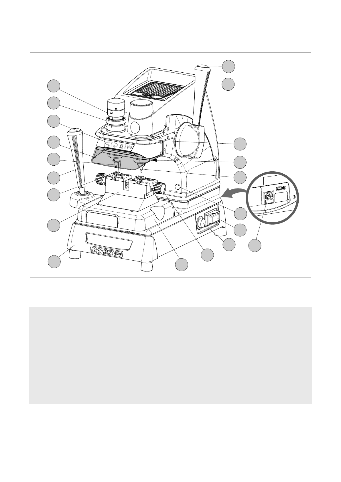
1.1 WORKING PARTS
D1
N
V
K
G
T
C
E
B
D
Q
R
J
F
W
P
Z
S
A - clamp carriage (X-Y axes)
B - clamp
C - clamp carriage lever (X-Y axes)
D - vertical carriage lever (Z axis)
D1- lever release and motor start button
E - left-hand clamp knob
E1- right-hand clamp knob
F - cutter
G - transparent safety shield
J - lamp
E1
A
Fig. 5
K - calibration unit key pad
N - tracer point spring cam
P - ON/OFF switch
Q - motor ON switch
R - rollbar
S - tool box
T - tracer point
V - tracer point regulation micrometric ring
W- motor ON warning light
Z - power socket
6
Copyright Silca 2014
Page 11
Operating manual Matrix ONE
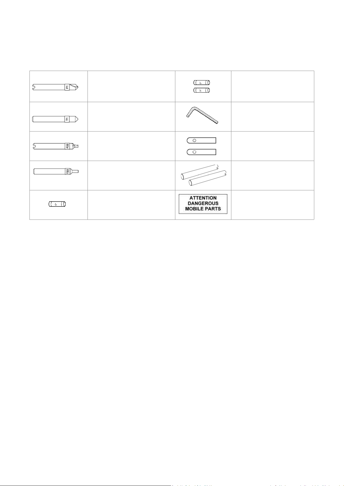
1.2 ACCESSORIES PROVIDED
MATRIX ONE comes with a series of accessories for use and maintenance (tools, hex wrenches, fuses, etc.)
provided in a special holder:
F1 cutter
T1 tracer point
F22 cutter Steel bar
T22 tracer point Calibration pins
fuse 1 pc)
500 mA rapid
1.3 TECHNICAL DATA
fuse 2 pcs
2,5 Amp rapid (230V)
2.5 mm hex wrench mm
Adhesive label
“DANGEROUS
MOBILE PARTS”
Power supply: 230V-50/60Hz - 0,75 Amp. - 170 Watt
Cutter motor: single phase 1 speed motor 230V 50/60Hz
Cutters: Super speed steel
Tool speed: 6000 rpm (for cutters in super speed steel)
Movements: on 3 axes by ball guides
Clamps: fi xed with interchangeable plates
Runs: X axis: 40 mm - Y axis: 50 mm - Z axis: 30 mm
Dimensions:
Illumination: LED lamp
Mass: Kg. 24,6
Noise rating:
width: 310 mm (maximum lever operating space 400 mm)
depth: 400 mm height: 470 mm
Lp (A) = 70,5 dB (A) brass dimple keys
Lp (A) = 75,9 dB(A) brass keys with laser cuts
Lp (A) = 76,6 dB(A) steel keys with laser cuts
Copyright Silca 2014
7
Page 12

Operating manual Matrix ONE
1.4 ELECTRIC DIAGRAM
1) Fuses: 2,5 Amp (230V)
2) Safety switch
3) Terminal board
4) Motor ON/OFF switch
5) Motor 6,3 mF (230V)
6) Motor warning light (LED)
7) Motor safety microswitch
8
Fig. 6
8) Transformer
9) LED circuit
10) LED lamp
11) Tracer point contact
12) Cutter contact
13) Condenser
14) Fuse 500 mA - rapid
Copyright Silca 2014
Page 13
Operating manual Matrix ONE
2 HANDLING
The MATRIX ONE key-cutting machine is easy to handle and there are no special hazards involved in moving it.
The packed machine can by carried manually by one person.
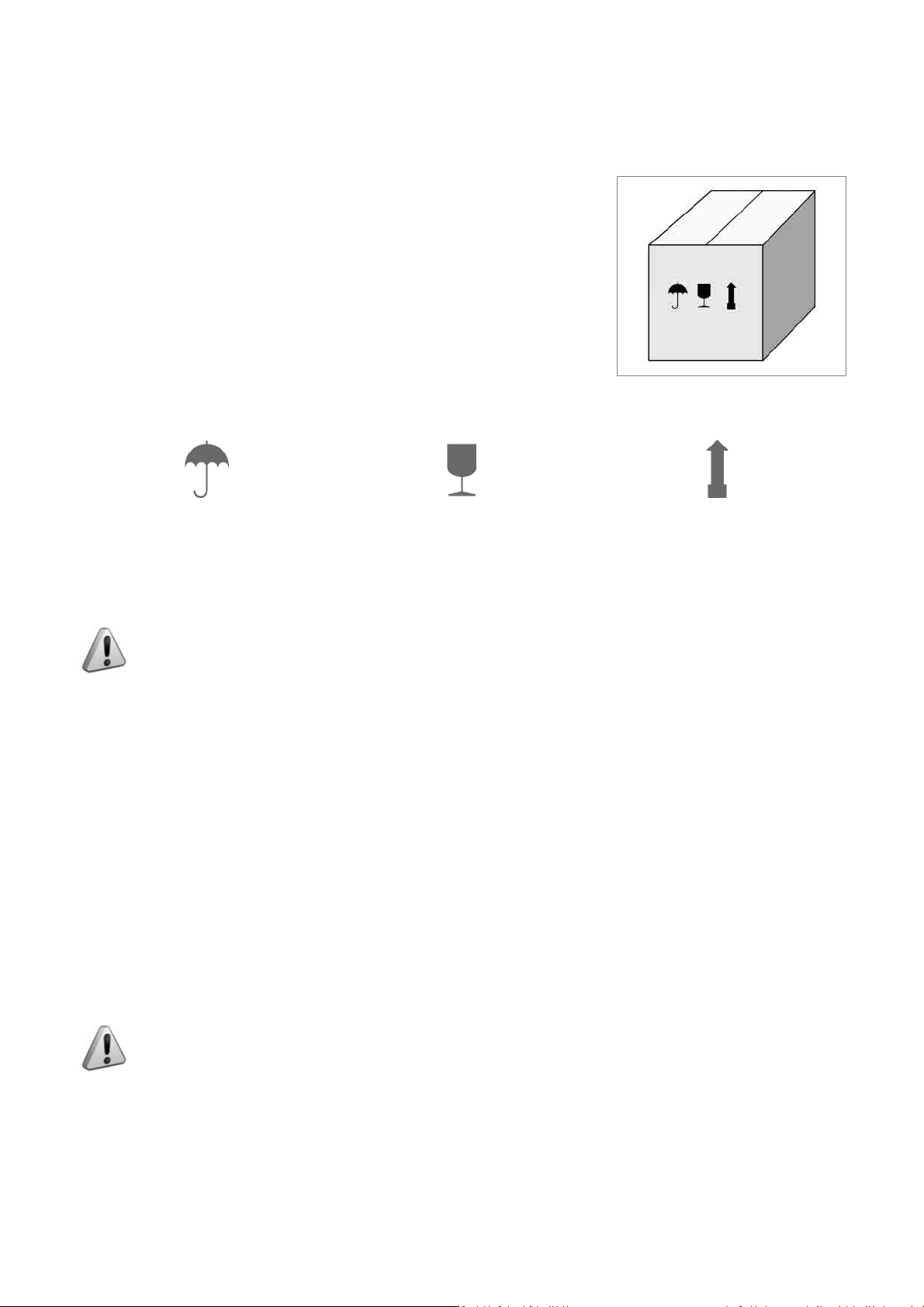
2.1 PACKING
The packing for the MATRIX-ONE key-cutting machine ensures safe handling
of the machine and all its components.
Packing comprises expanded plastic material wrapped around the machine.
The robust cardboard box in which it is placed and the nylon wrapping protect
the machine even when stored for a long period.
Fig. 7
Keep dry Handle with care Up
2.2 TRANSPORT
The symbols on the outside of the cardboard box give indications for transport.
ATTENTION: keep the complete packing for future machine transfers.
2.3 UNPACKING
To remove the machine from its packing:
1) Cut the strapping with scissors and remove.
2) Open the box carefully without damaging it.
3) Free the machine from the protective shells.
4) Check the contents of the packing, comprising :
-
MATRIX-ONE key-cutting machine.
-
Documentation comprising: user’s manual, spare parts sheet, specialist guide and warranty.
-
Power lead.
-
Tool holder.
2.4 HANDLING THE MACHINE
Once removed from its packing place MATRIX-ONE directly on the work bench; one person can easily perform
this operation.
ATTENTION: lift the machine by holding onto the base. Never lift the machine by gripping the
clamps, levers or other parts.
Copyright Silca 2014
9
Page 14

Operating manual Matrix ONE
3 MACHINE INSTALLATION AND PREPARATION
Installation is the customer’s task and does not require any special skills.
The key-cutting machine is supplied ready for use and does not need calibration except for the tools to be used;
however, the operator is required to make certain checks and prepare the machine for use.
3.1 CHECKING FOR DAMAGE
MATRIX ONE is a solid compact machine and will not break if handling, unpacking and installation are carried out
to the instructions in this manual. However, it is good practice to check that the machine has not been damaged.
3.2 ENVIRONMENTAL CONDITIONS
To make the most of the key-cutting machine, bear in mind the following environmental parameters: it is advisable
for the area to be dry with good air circulation.
The optimum environmental conditions for machine operation are:
-
temperature 10° C to 40°C; - relative humidity: approx 60%.
3.3 POSITIONING
1) Place the key-cutting machine on a solid horizontal work bench suitable for the weight of the machine (24,6
Kg). The work bench should be approximately 100-120 cm high to facilitate access to the working parts. We
recommend leaving at least 30 cm clearance behind and around the machine to ensure good ventilation and
facilitate handling (Fig. 9) .
2) Make sure machine voltage is suitable for the mains supply and that the latter is earthed with a differential
switch.
3) Place the adhesive label “DANGEROUS MOBILE PARTS” (provided) in the appropriate language in position as
shown in Fig. 8.
4) Connect the power lead to the machine ( Fig. 10).
Fig. 8
Fig. 9 Fig. 10
3.4 SAFETY DEVICES
• ON/OFF master switch (P)
The master switch (P) is electromagnetic and turns the machine off automatically when power fails. When power
returns the switch must be reset manually to provide the machine with voltage.
• Push button (D1) to release the lever and start the motor
When push button (D1) is not activated there is no risk of involuntarily or accidentally moving the lever (D) and
preventing the motor from starting.
• Warning light (W) cutter motor on
The right-hand front part of the machine (behind the clamp unit) has a warning light (W). The warning light fl ashes
when the cutter motor is on.
10
Copyright Silca 2014
Page 15

Operating manual Matrix ONE
3.5 WORK STATION DESCRIPTION
The machine is operated by a single person using the following controls:
• ON/OFF master switch (P) located on the righthand side of the machine.
D1
• Motor ON/OFF switch (Q).
• Vertical carriage lever (D) with push button (D1)
to release the lever and start the motor.
K
D
• Clamp unit
• Lever (left-hand) (C)
• Key pad (calibration and illumination) (K )
C
P
Q
Fig. 11
• ORGANIZER SHELF (Z)
The top part of the cover incorporates an area for the operator to use as a place for things such as key blanks or
cut keys. It is advisable not to put too many things in this area, as they could accidentally fall off .
• ROLLBAR (R)
The purpose of this special bar is to assist the operator
during key cutting. It is used as a rest for the left hand
when moving the clamp carriage (centering cuts on
dimple keys or cutting path for laser keys). It ensures
smooth synchronised carriage movements during cutting
operations.
• TRANSPARENT SAFETY SHIELD (G)
Special plexiglass shield to limit the dispersal of swarf .
• TOOL BOX (S)
In the bottom part of the machine front, under the clamp
unit carriage, there is a tool box with an open part to use
as a handle for pulling out the box. Inside it has 20 spaces
for holding tracer points and cutters, and a larger area for
other small tools and/or keys.
Fig. 12
Copyright Silca 2014
11
Page 16

Operating manual Matrix ONE
3.6 STARTING THE KEY-CUTTING MACHINE
1) Connect the power lead.
2) Turn on the key-cutting machine with the master switch (P). A beep sounds and for a second all the warning
lights (leds) on the key pad/control board (K) light up simultaneously on the machine front (blue vertical bar –
green vertical bar -2 red arrows) (Fig. 3).
3) When the beep stops only the blue warning light stays on to indicate that the machine is live.
Nota: if the conditions described above do not occur, see chap.6.7.
3.6.1 STARTING THE MOTOR
With the machine connected and on:
1) press the luminous switch (Q) to power the motor (Fig. 11).
2) Press the push button (D1) on the vertical axis lever (D) and lower the lever.
ATTENTION: if the motor does not start and the lever (D) will not move, check that the lever is
fully tightened.
A fl ashing warning light (W) signals that the motor is on (chap.3.6.2). Attention: cutter in motion!
3) To turn off the motor release the lever (D) or turn off one of the 2 switches (P) or (Q).
3.6.2 CUTTER MOTOR ON WARNING LIGHT
There is a warning light (W) on the right-hand part of the machine
front (behind the clamps unit (Fig. 13).
When the cutter motor is on the warning light fl ashes.
3.6.3 LED LAMP
When the key-cutting machine is turned on the lamp is off.
Lightly touch the button (J1) to turn the lamp on or off.
J1
W
Fig. 13
12
Fig. 14
Copyright Silca 2014
Page 17

Operating manual Matrix ONE
4 MACHINE CALIBRATION AND REGULATION
Before carrying out cutting operations the clamps and tools must be regulated. According to the type of key to be
cut, activate or deactivate the spring device provided with the machine to facilitate cutting operations:
• Vertical spring for the tracer point used for dimple keys (chap.4.4) .
4.1 FITTING AND REMOVING TOOLS
Fig. 15
ATTENTION: carry out this operation with the cutter motor off.
Lever (D) fully raised.
Clamp carriage lever (C) fully down .
Tracer point
Fitting:
-
insert the tracer point all the way into the spindle with the numbered ring towards the clamp.
-
hold the tool in this position and tighten the grub screw (G3) with the hex wrench provided.
Removing:
-
loosen the grub screw (G3) with the hex wrench and remove the tool .
Cutter
Fitting:
-
insert the cutter into the spindle with the numbered ring towards the clamp.
-
hold the tool in this position and tighten the grub screw (G4) with the hex wrench.
Removing:
-
loosen the grub screw (G4) with the hex wrench and remove the tool.
G3
Fig. 16
Copyright Silca 2014
G4
13
Page 18

Operating manual Matrix ONE
4.2 MICROMETER GAUGE
The micrometer gauge is used for tool alignment and also for
adjusting small variations in depths often necessary on worn
keys.
After tool alignment (green bar) the depth of cuts can be
reduced or increased by turning the micrometer gauge (V) to
the left or right.
Each line on the gauge corresponds to a displacement of
0,02 mm.
V
Fig. 17
• Turn the gauge clockwise to make cuts less
deep.
• Turn the gauge anti-clockwise to make cuts
deeper.
14
Copyright Silca 2014
Page 19

Operating manual Matrix ONE
4.3 CALIBRATION / TOOL ALIGNMENT
Carry out this operation with the key-cutting machine on.
ATTENTION: check that the motor start switch (Q) is off.
1) Turn the cam (N) clockwise all the way to disable the tracer point spring (chap.4.4).
2) Fit and secure the two tools (tracer point and cutter) in their respective spindles.
3) Press the button (K1) on the front of the machine to enable the key pad/control board.
Fig. 18
4) Press the lever (D) release button (D1), lower the vertical carriage and take the tools into contact with the clamp
surface (seat of the key) (Fig. 19). There are three possibilities:
• Central green bar illuminated - Green arrows illuminated - CALIBRATION OK
In this case both tools are in contact with the keys and aligned.
Nota: from this position it is advisable to turn the gauge (V) clockwise by a couple of clicks.
• Left-hand red arrow illuminated - Tracer point side
In this case only the tracer point is in contact with the key.
Hold the vertical carriage down and turn the gauge (V) anti-clockwise in the direction of the illuminated arrow.
Calibration is complete as soon as the green vertical bar illuminates together with the two green arrows.
• Right-hand red arrow illuminated - Cutter side
In this case only the cutter is in contact with the key.
Hold the vertical carriage down and turn the gauge (V) clockwise in the direction of the illuminated arrow so that
the red light on the left-hand arrow goes on. From this position hold down fi rmly the right-hand lever and turn the
gauge (V) one click at a time. Calibration is complete as soon as the green vertical bar illuminates together with
the two green arrows.
ATTENTION: at the end of calibration press the button (K1) to disable the key pad/control
board.
5) Now it’s possible to proceed with duplication.
Copyright Silca 2014
15
Page 20

Operating manual Matrix ONE
D1
N
V
D
Fig. 19
4.4 TRACER POINT SPRING
The machine comes with a rapid system for enabling or disabling the tracer point spring.
• To enable the tracer point spring function
Turn/push the cam (N) all the way anti-clockwise .
N
Fig. 20
• To disable the tracer point spring function
Turn/push the cam (N) all the way clockwise ).
Enable the tracer point spring :
-
to cut dimple keys .
Disable the tracer point spring :
-
for calibration operations
-
to cut keys with laser cuts and vehicle keys in
general.
16
Copyright Silca 2014
Page 21

Operating manual Matrix ONE
4.5 CLAMPS
Clamps come with easily replaced special key-locking jaws (B1) (B2) and (B3).
B1
B2
B1
B3
Fig. 21
KEYS WITH DIMPLE CUTS AND LASER KEYS
Fig. 22
Copyright Silca 2014
17
Page 22

Operating manual Matrix ONE
5 CUTTING
ATTENTION: Please see the following warnings to ensure completely safe cutting operations:
• Always work with dry hands.
• Check that the machine is earthed.
• Wear the safety goggles even when the machine has a safety shield.
• Start the motor only after completing the following operations:
-
fi tting keys into the clamps
-
fi tting and calibrating tools .
• Keep your hands out of the way of the cutter in motion.
• Cut the key only if calibration has taken place:
-
insert the necessary tools
-
turn on the key-cutting machine
-
disable the tracer point spring
-
proceed with calibration.
5.1 FITTING KEYS
1) Take the clamp carriage towards the operator until you feel the limit switch click.
2) Fit the original key into the left-hand clamp and the key to be cut into the right-hand clamp, paying attention to
the type of stop on the key .
3) secure the keys with the knobs (E) (E1) .
5.2 KEY STOP
The notches 0-1-2-3 on the clamp are used according to the type of key stop:
-
0: for keys with back stop (towards head - Fig. 23).
-
1-2-3: for keys with tip stop (Fig. 24)
Choice of stops 1 - 2 - 3 is determined by the length of the key stem.
ATTENTION: the cutting path must always lie within the clamp surface .
Fig. 23 Fig. 24
After fi tting the keys into the clamps, follow the instructions for the type of key to be cut (chap.5.3 Cutting dimple
keys; chap.5.4 CUTTING laser TYPE keys).
18
Copyright Silca 2014
Page 23

Operating manual Matrix ONE
5.3 CUTTING DIMPLE KEYS
1) Enable the tracer point spring (chap. 4.4).
2) Press the motor on switch (Q).
3) Insert the two keys into their clamps.
4) Take care when positioning the keys:
-
Stop 0 for keys with stops.
-
Stop 1 / 2 / 3 for keys without stops, using the bar provided for tip .
Attention:
5) Grip the levers (C) and (D).
6) Press the button (D1) and lower the vertical carriage to start the motor.
7) Hold the carriage with the left-hand lever (C), lower the tool unit by means of the right-hand lever (D) until the
tracer point tip centres one of the holes. Continue to lower the lever (using the tracer point spring function) to
reach the cutting depth.
8) Repeat this operation for each hole on the key.
9) End cutting on the fi rst side, release the lever (D) to stop the motor.
10) Remove the cut key only and place it on the second side (the key has the same cuts on both sides).
11) Proceed with cutting side 2.
if the bar is used, remove it before making the cuts
.
0
Fig. 25
5.3.1 BACK CUTS
If there are cuts on the back of the key, stand it upright on the bottom of
the clamp (Fig. 26).
Fig. 26
Copyright Silca 2014
19
Page 24

Operating manual Matrix ONE
5.4 CUTTING LASER TYPE KEYS
1) Disable the tracer point spring (chap. 4.4).
2) Turn on the motor with the switch (Q).
3) Insert the two keys into their clamps.
4) Take care when positioning the keys:
-
Stop 0 for keys with stops (chap. 5.2).
-
Stop 1 / 2 / 3 for keys without stops, using the bar provided for tip stop (chap. 5.2).
Attention:
5) Grip the levers (C) and (D).
6) Press the button (D1) and lower the vertical carriage to start the motor.
7) Keep the clamp carriage still with the left-hand lever (C) and lower the tool unit by means of the right-hand lever
(D) until the tracer point reaches the cutting depth.
8) Without exerting pressure, turn the lever (D)
clockwise to lock the height reached.
9) Move the lever (C) to trace all the cuts on the key
with the tracer point.
• For right-hand cuts it is advisable to make the
cuts by moving the tracer point from the head
to the tip.
• For left-hand cuts it is advisable to make the
cuts by moving the tracer point from the tip to
the head.
10) When side 1 has been cut, turn off the motor with
the switch (Q).
11) Remove the key blank only and turn it 180° to cut
side 2. The key has the same cuts on both sides.
12) Start the motor with the switch (Q) and make the
cuts.
if the bar is used, remove it before making the cuts.
D
Fig. 27
20
Fig. 28
Copyright Silca 2014
Page 25

Operating manual Matrix ONE
5.5 CUTTING LASER KEYS WITH NARROW STEMS (MERCEDES) WITH OPTIONAL
ADAPTER “M”
code D910533ZR
Fig. 29
HU41P - HU64P - HU64T - HU81T HU55P
Fig. 30
5.6 CUTTING FICHET TYPE KEYS (H PROFILE) WITH OPTIONAL ADAPTER “F”
code D910534ZR
Fig. 31
Fig. 32
Copyright Silca 2014
21
Page 26

Operating manual Matrix ONE
6 MAINTENANCE
ATTENTION: when repairing or replacing parts the “CE” label is guaranteed only if original
spare parts provided by the manufacturer are used.
The MATRIX ONE key-cutting machine does not need special maintenance, but it is good practice to check and
if necessary replace parts subject to wear: belts, lamp and vertical carriage spring.
Replacement operations are simple and can be performed by the operator.
CLEANING: it is advisable to keep the carriage and clamps clean by regularly brushing away the swarf deriving
from cutting operations.
ATTENTION: DO NOT USE COMPRESSED AIR!
ATTENTION: to maintain machine effi ciency we recommend using protective oil such as
WD40 or similar to apply to the burnished mechanical parts. This will prevent oxidation of the
parts in question (clamps, guides, carriages...). Make sure the oil does not come into contact
with the electronic parts.
Before performing any type of maintenance (checks or replacements) read the warnings below:
• Do not perform any maintenance operations with the machine on.
• Always disconnect the power lead.
• Follow the instructions in the manual carefully.
• Use original spare parts .
6.1 TIGHTENING AND REPLACING THE BELT
If vibrations occur on the top part of the key-cutting machine, check the state and tightness of the belt in the way
described:
1) Turn off the master switch and disconnect the power lead .
2) Loosen the 6 screws (Y1) and remove the top safety guard (Y).
3) Loosen (without removing) the 4 allen screws (Y2) securing the motor (Fig. 34).
Y
Y1
Y1
Fig. 33
22
Y2
Fig. 34
Copyright Silca 2014
Page 27

Operating manual Matrix ONE
Tightening:
Increase belt tension by pushing the motor towards the back of the machine .
Replacing:
1) Loosen the belt by pushing the motor gently towards the tracer point and cutter.
2) Remove the belt and replace.
3) Tighten by pushing the motor towards the back of the machine.
• secure the motor by tightening the 4 allen screws (Y2).
• replace the top safety guard (Y) and secure with the 6 screws (Y1).
Fig. 35
6.2 REMOVING THE UPPER FRONT UNIT
1) Switch the machine off and disconnect the power lead.
2) Remove the 2 screws (R1) securing the rollbar (Fig. 36).
3) Loosen the 4 screws (K2) securing the upper front unit (K5) and remove.
6.3 REPLACING THE ROLLBAR
1) Remove the upper front unit (K5) (chap6.2).
2) Loosen the 3 screws (R3) and remove the rollbar (R) (Fig. 37).
3) Fit the new rollbar and secure with the 3 screws (R3).
4) Replace the upper front unit on the machine and secure with the 4 screws (K2).
5) Secure the rollbar with the 2 screws (R1).
Copyright Silca 2014
23
Page 28

Operating manual Matrix ONE
6.4 REPLACING THE TRANSPARENT SAFETY SHIELD
1) Remove the upper front unit (chap6.2).
2) Use a screwdriver to detach the shield from the upper front unit.
3) Attach the new shield to the upper front unit.
4) Replace the cover on the machine and secure with the 4 screws (K2).
5) Secure the rollbar with the 2 screws (R1) .
R1
R1
K2
K2
Fig. 36 Fig. 37
6.5 REPLACING THE LAMP
Follow the instructions below to replace the lamp:
1) Remove the upper front unit (chap6.2).
2) Disconnect the connector (J4) (Fig. 38).
3) Loosen and remove the 2 screws (J1) securing the lamp glass (Fig. 39).
4) Loosen and remove the 2 screws (J3) securing the LED board.
5) Pull the LED lamp downwards.
6) Fit the new LED board so that the wire passes over the top and connect the connector to the board.
7) Secure the new board with the 2 screws (J3).
8) Secure the lamp glass with the 2 screws (J1).
9) Connect the connector (J4).
10) Replace the upper front unit on the machine and sec ure with the 4 screws (K2).
11) Secure the rollbar with the 2 screws (R1).
J3
24
J1
Fig. 38 Fig. 39
Copyright Silca 2014
Page 29

Operating manual Matrix ONE
6.6 ADJUSTING/REPLACING THE VERTICAL CARRIAGE SPRING
If the vertical carriage (Z axis) seems loose it is advisable to adjust the spring and replace if necessary. Proceed
as follows:
1) Switch off the machine and disconnect the power lead.
2) Remove the 6 screws (Y1) to detach the top safety guard (Y) (Fig. 33).
3) Loosen the 4 screws (Y3) and remove the rear panel (Fig. 40).
4) Turn the machine so that its back faces the operator.
To increase spring tightness:
-
perform operations 1 and 2 shown in Fig. 42.
To decrease spring tightness:
-
perform operations 1 and 2 shown in Fig. 43.
5) Replace the safety guard (Y) and secure with the 6 screws (Y1) (Fig. 33).
To replace the spring:
-
follow the instructions in points 1. 2. 3.
-
replace the spring and adjust tightness .
Y3
Fig. 40
Fig. 41 Fig. 42 Fig. 43
Copyright Silca 2014
25
Page 30

Operating manual Matrix ONE
6.7 CHECKING AND REPLACING FUSES
Fuses should be checked with an instrument for measuring continuity (tester, ohmeter, multimeter, etc.) as they
may appear normal to the eye even when electrically damaged. Each fuse must be replaced with one of the same
value (Amperes) and type (rapid or delayed), as shown in the manual. The MATRIX ONE key-cutting machine
has:
2 fuses:
2,5 Amperes rapid on the 230 Volt key-cutting machine
L ocated in the mains socket, they protect the machine from
voltage variations and possible short circuits.
If the machine does not go on when the switch is activated,
it is advisable to check the fuses in the way described:
1) Turn off the machine with switch (P) and disconnect
the power lead.
2) Use a screwdriver to remove the fuses .
Fig. 44
1 fuse:
500 mA rapid
situated on the terminal board, it protects the calibration keypad circuit board from possible short circuiting. Check
the fuse when the blue LED does not illuminate with the machine on (circuit board not powered).
Follow the instructions below:
1) Turn off switch (P) and detach the power lead .
2) Place the key-cutting machine on its back and loosen the 4 screws (P4) to remove the bottom safety plate (Fig.
52).
3) Take the fuse out of its seat (V3) (Fig. 45 and Fig. 46).
4) Replace and secure the bottom safety plate with the 4 screws (P4).
5) Return the key-cutting machine to its proper position.
26
Fig. 45 Fig. 46
Copyright Silca 2014
Page 31

Operating manual Matrix ONE
6.8 REPLACING THE CALIBRATION KEY PAD ELECTRONIC CIRCUIT BOARD
If the key pad (K) is not working properly replace the electronic circuit board inside it as described below:
1) Remove the upper front unit (chap6.2).
2) Detach the connectors (J4 and (R4) (Fig. 47).
3) Remove the 4 screws (a) (b) (c) (d) paying attention to the position of the wires.
4) Remove the 2 screws (K4) fi xing the circuit board.
5) Replace the circuit board, secure with the 2 screws and re-connect the 2 connectors (J4) and (R4) and the 4
wires with screws (a) (b) (c) (d).
6) Replace the upper front unit on the machine and secure with the 4 screws (chap6.2).
7) Secure the rollbar with the 2 screws (R1) (chap6.3).
Fig. 47
6.9 REPLACING THE CONDENSER
1) Switch off the machine and disconnect the power lead.
2) Loosen the 6 screws (Y1) and remove the top cover (Fig. 33).
3) Move the protective cap on the condenser (Fig. 49).
4) Disconnect the connectors from the condenser, paying attention to their position.
5) Loosen the condenser fi xing nut (C3).
6) Connect the connectors to the new condenser and replace the protective chap.
7) Secure the condenser with the nut (C3).
8) Replace the top cover and tighten the 6 screws (Y1).
C3
Fig. 48 Fig. 49
Copyright Silca 2014
27
Page 32

Operating manual Matrix ONE
6.10 REPLACING THE MOTOR
1) Disconnect the key-cutting machine from the mains.
2) Loosen the 6 screws (Y1) and remove the top cover (Fig. 33).
3) Loosen the 2 screws (W1) fi xing the motor wires to the terminal board and the screw on the earth wire (W2).
4) Loosen the 4 screws (Y2) securing the motor.
5) Remove the motor pulley belt.
6) Loosen the grub screw (P2) securing the motor pulley and pull upwards to remove (Fig. 51).
7) Grip the motor with one hand and use the other to loosen and remove the 4 screws (Y2).
8) Pull the motor out from back of the machine.
P2
Fig. 50 Fig. 51
6.11 REPLACING THE TRANSFORMER
1) Disconnect the power lead from the machine.
2) Turn the key-cutting machine on its back and loosen the 4 screws (P4) to remove the bottom safety guard (Fig.
52).
3) Loosen the 2 screws (Z2) fi xing the low voltage (transparent) cables (20V) (Fig. 53).
4) Loosen the 2 screws (Z3) fi xing the mains supply wires (a wire in position 0 and a wire corresponding to the
voltage being used).
5) Loosen the 4 screws (T3) securing the transformer and remove.
6) Install and secure the new transformer with the 4 screws (T3).
7) Use the screws (Z2) to fi x the 2 transparent low voltage cables in the 12 Volt connectors on the transformer.
8) Secure the 2 mains supply wires to the connectors on the transformer (a wire in position 0 and one
corresponding to the voltage being used), with their screws (Z3).
Take care that the position is correct according to the voltage (Fig. 53).
9) Replace and secure the bottom safety guard with the 4 screws (P4).
10) Return the key-cutting machine to the upright position.
28
Copyright Silca 2014
Page 33

Operating manual Matrix ONE
P4
Fig. 52 Fig. 53
6.12 REPLACING SWITCHES: MASTER AND MOTOR ON
1) Disconnect the power lead from the machine .
2) Turn the key-cutting machine onto its back and loosen the 4 screws (P4) to remove the bottom safety guard
(Fig. 52).
3) Disconnect the wires from the switch to be replaced, paying attention to their position.
4) Press the fi xing “tabs” on the switch so that it can be pulled out.
5) Insert the new switch into the special seat.
6) Reconnect the connectors.
7) Replace and secure the bottom safety guard with the 4 screws (P4).
8) Return the key-cutting machine to the upright position.
Fig. 54 Fig. 55
Copyright Silca 2014
29
Page 34

Operating manual Matrix ONE
6.13 ALIGNING/CALIBRATING THE CLAMP
The key-cutting machine comes from Silca with the clamp perfectly aligned. Alignment is necessary only if a jaw
has to be replaced.
1) Make sure the motor ON switch is OFF.
2) Fit and secure the 2 calibrating pins (provided) to the 2 spindles as if they were tools. N.B.: the fl at part (with
greater diameter) must be visible (towards the clamp).
3) Turn on the key-cutting machine with the master switch (P).
4) Enable the key pad /calibration control board with key (K1).
5) Disable the tracer point spring (chap4.4).
D
Fig. 56 Fig. 57
6.13.1 CONTROL ALIGNMENT LEFT-HAND STATIONARY JAWS
1) Lower the vertical carriage with the lever (D) (Fig. 57).
2) Align the 2 pins on the key surface (chap4.3).
3) When the pins are aligned, raise them slightly with the lever (D) so that they are not in contact with the key
surface.
4) Turn the lever (D) clockwise to lock the height of the vertical carriage.
5) Move the clamp carriage with the lever (C) and take the pins into contact with several points on the left-hand
jaw (also on the side of Stop 0). If the calibration board shows a green light the fi xed-hand jaws are aligned.
6) If not, loosen the 2 screws (B7) and regulate the jaw (if necessary, loosen the 2 nuts (B4) and regulate the 2
grub screws B5) until the condition described above is achieved.
30
Fig. 58
Copyright Silca 2014
Page 35

Operating manual Matrix ONE
B6
B6
B5
B5
B4
B4
Fig. 59
B7
B7
6.14 REPLACING THE JAWS
Make sure the motor ON switch is OFF .
6.14.1 REPLACING THE FIXED JAWS
1) Loosen the 2 screws (B6) or (B7) and remove the jaw .
2) Fit the new jaw up against the left-hand side and align also from the front (Fig. 61).
3) Tighten the 2 screws (B6) or (B7) without exerting pressure.
4) Check alignment (chap.6.13.1) and then fully tighten the screws (B6) or (B7).
Fig. 60 Fig. 61
Copyright Silca 2014
31
Page 36

Operating manual Matrix ONE
6.14.2 REPLACING MOBILE JAW ON LEFT-HAND CLAMP
1) Fully unscrew the knob (E).
2) Loosen the 2 screws (H3) and remove the plate (H4) (Fig. 62) .
3) Remove the mobile jaw and clean the clamp (Fig. 63).
4) Fit the new jaw and then screw in the knob.
5) Replace the plate (H4) and tighten the 2 screws (H3).
H3
H4
E
Fig. 62 Fig. 63
6.14.3 REPLACING MOBILE JAW ON RIGHT-HAND CLAMP
1) Fully unscrew the knob (E1).
2) Loosen the 2 screws (U3) and remove the plate (U4) (Fig. 64).
3) Remove the mobile jaw and clean the clamp (Fig. 65).
4) Fit the new jaw, replace the plate (U4) and tighten the 2 screws (U3).
5) Screw in the knob (E1).
U3
E1
U4
32
Fig. 64 Fig. 65
Copyright Silca 2014
Page 37

Operating manual Matrix ONE
7 DISPOSAL
For correct disposal please refer to current standards.
INFORMATION FOR USERS OF PROFESSIONAL EQUIPMENT
From “Actuation of Directive 2012/19/EU regarding Waste Electrical and Electronic Equipment (WEEE)”
The symbol of a crossed waste bin found on equipment or its packing indicates that at the end of the product’s
useful life it must be collected separately from other waste so that it can be properly treated and recycled.
In particular, separate collection of this professional equipment when no longer in use is organised and managed:
a) directly by the user when the equipment was placed on the market before 31 December 2010 and the
user personally decides to eliminate it without replacing it with new equivalent equipment designed for the
same use;
b)
by the manufacturer, that is to say the subject which was the fi
that replaces previous equipment, when the user decides to eliminate equipment placed on the market
before 31 December 2010 at the end of its useful life and replace it with an equivalent product designed
for the same use. In this latter case the user may ask the manufacturer to collect the existing equipment;
c)
by the manufacturer, that is to say the subject which was the fi
that replaces previous equipment, if it was placed on the market after 31 December 2010;
Suitable separate collection for the purpose of forwarding discarded equipment for recycling, treatment or disposal
in an environmentally friendly way helps to avoid possible negative effects on the environment and human health
and encourages re-use and/or recycling of the materials making up the equipment.
The sanctions currently provided for by law shall apply to users who dispose of products in unauthorised ways .
rst to introduce and market new equipment
rst to introduce and market new equipment
Copyright Silca 2014
33
Page 38

Operating manual Matrix ONE
8 AFTER-SALES SERVICE
Silca provides full service to purchasers of the MATRIX ONE machine. To ensure total safety for the operator and
the machine, any operations not specifi ed in this manual shall be carried out by the manufacturer or in the special
Service Centres recommended by Silca.
On the back cover of the manual there is a list of the manufacturer’s addresses; the following page lists the
addresses of specialized Service Centres.
8.1 HOW TO APPLY FOR AFTER-SALES SERVICE
The warranty attached to the MATRIX ONE machine guarantees free repairs or replacement of faulty parts within
24 months of purchase. Any other operation shall be agreed by the user with Silca or its Service Centres.
34
Copyright Silca 2014
Page 39

VITTORIO VENETO 13/01/2014
CE DECLARATION OF MACHINE COMPLIANCE
SILCA S.p.A. - VIA PODGORA 20 ( Z.I.)
31029 VITTORIO VENETO (TV) - (ITALY)
TEL. 0438 9136 - FAX. 0438 913800
Declares under its own responsibility that the Key-cutting machine model
MATRIX ONE
complies with the requirements of the following European Directives:
European Union DIRECTIVE 2006/42/CE (Machines)
and with the EN 12100 Standards
European Union DIRECTIVE 2004/108/CE
and with the EN 55022 ; EN 55024 ; EN 61000-3-2 ; EN 61000-3-3 Standards
European Union DIRECTIVE 2006/95/CE
and with the EN 60950-1 ; EN 62233 Standards
Claudio Tomasella of the Silca S.p.A. Research & Development Division is authorized
to create a Technical File.
General Manager Basic Production Center
(Electromagnetic Compatibility)
(Low Voltage) | 14 |
Page 40

SERVICE CENTERS - CENTRI DI ASSISTENZA - KUNDENDIENSTZENTREN - CENTRES D’ASSISTANCE
CENTROS DE ASISTENCIA - CENTROS DE ASSISTÊNCIA - BIJSTANDSCENTRA
COUNTRY COMPANY ADDRESS CITY
Algeria
Argentina
Australia
Austria
Belgium
Brazil
Bulgaria
Burkina
Faso
China
Colombia
Croatia
Cyprus
Czech
Republic
Denmark
Egypt
Finland
France
Germany
Greece
Greece
Greece
Greece
Guinea
Holland
Holland
Holland
Hong Kong
Hungary
India
Iran
Israel
Italy
Japan
Sarl Maghreb Clés
Distribuidora
Frappampino S.r.l.
Locksmiths' Supply Co.
Pty Ltd.
Erwe Gmbh Feldgasse, 16 Feldkirchen A-9560 +43-42762816
Duitman Bvba Zinkstraat 13 Halle 1500 +32-2-3831620
Kaba Do Brasil Ltda.
Intesa S.r.l. 1, Kukush Sofia 01309 +359-2-8211425
Diallo Mamoudou
Silca China Xinhua Industrial Zone
Flexon Llaves S.A.
Ferrotechna d.o.o. Japodska, 66c Pula 52100
G.H. Yacoubian Ltd. 74/B, Regaena Street Nicosia +357-22-663525
H&B Plus. s.r.o. Zatecká, 8 Plzen 30148 +420-377-225903
Agenturcentret A.S Brydehusvej 20 Ballerup 2750 +45-70111211
Gam Transworld
Hardware Group Finland
Oy. (Hgf Ltd)
SILCA S.A.S.
SILCA GmbH Siemensstrasse, 33 Velbert 42551 +49-2051-2710
Chrisikos K. Ioannhs 7 Pipsou St. Thessalonik
F. Sotiropoulos & Son
O.E.
GEMKA-Karidis
G. & Sons OE
Fr.lli Raptakis Pili Iisou 10 Iraklion - Crete +30-2810-285000
Soguintec S.A. Calle Abilio Baloboa
Duitman B.V. Aquamarijnstraat 5 7554 NM - Hengelo +31-74-2452520
H. Cillekens & Zn. B.V. Metaalweg, 4 JB Roermond 6045 +31-475-325147
Steenhauer B.V. Oude Raadhuisstraat 1 Ap Leidschendam 2266 +31-70-3177262
Professional Lock Centre
Co. Ltd.
Kaba Elzett Megyeri út 51 Budapest 1044 +36-1-3501011
Minda Silca Engineering
Ltd.
Klidavarshayan Co.
A.M.C.I. Locksmith
Supply Ltd.
SILCA S.p.A. Via Podgora, 20 (Z.I.) Vittorio Veneto - TV 31029 +39-0438-9136
Clover Co. Ltd
Coopérative Ettadhamoune
Local 21/A
La Rioja, 483 Cordoba 5000 +54-351-4216368
140/158 Dryburgh St. North Melbourne
Rua Guilherme Asbahr
Neto 510
Av.Houari Boumedienne
Porte N. 1651
Av.Carrera 70 No.99 - 55
Entrada 1
23 Omer Ibn El-Khatar
Street
Luostarinportti 5 Kirkkonummi 02400 +358-9-2219490
12, Rue de Rouen
B.P.37
Patission Str., 110 Athens 11257 +30-210-8234009
Lykoyrgoy St. 14-16 Athens 10552 +30-210-3243000
Unit A-D, 9/F.
Gemstar Tower,
23 Man Lock Street
Plot No. 37, Toy City Greater Noida 201308
No.73 Stakhr. St - Emam
Khomaini Ave.
22 Efal Street Kiryat Aryeh
P.O.Box 3667
1-2-40 Haradanaka,
Toyonaka-shi
Badjarah / Alger 16209 +213-21-264934
São Paulo
01BP / 2957
Ouagadougou 01
Guanghai County,
Taishan, Canton
Bogotà +571-2538300 +571-5331842
Heliopolis
El Cairo
Z.I. Limay
Porcheville
Malabo - Provincia
del Bioko Norte
Hunghom, Kowloon,
Hong Kong
Tehran +98-216-6702757
Petah Tikva 49130 +972-3-9230331
Osaka
AREA
CODE
VIC
3051
04646-
001
+226-710448
+86-750-5325698
78440 +33-1-30983500
TK
54627
+240-556618
+852-23302268
561-
0807
PHONE
+61-39-3297222
+55-11-5545-4510
+385-52-503-529
+385-52-502-609
+20-2-22404705
+20-2-26441401
+30-2310-510336
+91-987-397630
+91-987-397631
+81-6-6844-2111
asmaghreb_cle@yahoo.fr
frappampino@arnet.com.ar
kaba@kabadobrasil.com.br
dialloebauchedecles@yahoo.fr
ferrotechna@pu.t-com.hr
ghycy@spidernet.com.cy
agentur@agenturcentret.dk
g_karidis@yahoo.com
raptakis_keys@her.forthnet.gr
FAX
e-mail
+213-21-264888
+54-351-4229003
+61-39-3281731
lsc@lsc.com.au
+43-42765054
firma@erwe.at
+32-2-3831622
info@duitman.be
+55-11-5545-4515
+359-2-8211347
info@intesa.bg
+226-710002
+86-750-5315655
alan@tswahyat.com
+385-52-503-529
+357-22-669009
+420-377-225904
plzen@klice-hb.cz
+45-70111221
+20-2-22404705
gam@intouch.com
+358-9-2962186
asiakaspalvelu@hgf.fi
+33-1-30983501
info@silca.fr
+49-2051-271172
info@silca.de
+30-2310-521651
info@chrisikos.gr
+30-210-8238480
roulasot@otenet.gr
+30-210-3249571
+30-2810-280165
+31-74-2452522
info@duitman.nl
+31-475-325148
info@hcillekens.nl
+31-70-3177333
info@steenhauer.nl
+852-23302082
plc@plc.com.hk
+36-1-3290692
info@elzett.hu
+91-120-2351301
info@mindasilca.in
+98-216-735649
klidavar@yahoo.com
+972-3-9230332
amci@bezeqint.net
+39-0438-913800
silca@silca.it
+81-6-6844-1147
info@cloverkey.co.jp
Page 41

COUNTRY COMPANY ADDRESS CITY
Kenya
Kuwait
Latvia
Lebanon
Macedonia
Malta
Mexico
Mozambique
New
Zealand
Nigeria
Norway
Poland
Poland
Portugal
Portugal
Romania
Russia
Russia
Saudi
Arabia
Serbia
Singapore
Slovakia
South Africa
Spain
Sweden
Switzerland
Syria
Taiwan
Turkey
U.A.E.
Ukraine
United
Kingdom
U.S.A.
Venezuela
Yemen
MPPS Ltd. P.O. Box 31347 Nairobi
Hasawi & Sabano Co.
For Gen.Trad.
Solo F Ltd. Salaspils 12 Riga 1057 +371-7278359
Mouawad Books &
Stationary Sarl.
Panevski & Sinovi Llidenska , 11 Kumanovo 1300 +389-31-411545
Unimark Ltd. 32, Zerafa Str. Hmr 03 Marsa +356-21-231540
Corporacion Cerrajera
Alba Sa De Cv
Davel Importacao
Comercio e Servicos
Baber LSC Limited
Chilex Security Products
Ltd.
Prodib Ab Montorgat 16 Eskilstuna 632 29 +46-16-168000
Dar-Mar ul. Napoleona, 17 Kobylka 05-230 +48-22-7710118
Z.P.U.H. Expres
Wojcieck Kowalczyk
Casa Das Chaves Da
Falagueira Ltda
Luso Chav'
M&C Business S.r.l.
Strazh 16/2, pt. Komsomolskiy Moscow 119021 +7 495 7083440 +7-495-7083292
O.O.O. Peter Key Mihaylovsky Pereulok, 7b Saint Petersburg 198095 +7-812-2520241
Fahd Omar
Bamashmous Est.
Silkon D.O.O. 29, Novembra 70 Belgrade 11000 +381-11-2080200
Silca Soxxi Pte. Ltd.
H&B Slovakia s.r.o. Ovsistske Nam. 1 Bratislava 85104
Sanlic International (Pty)
Ltd.
Silca Key Systems S.A. C/Santander 73/A Barcelona 08020 +34-93-4981400
Prodib Ab Montorgat 16 Eskilstuna 632 29 +46-16-168000
Robert Rieffel Ag Widenholzstrasse 8 Wallisellen 8304 +41-44-8773333
Muheiddin Arabi Katbi P.O. Box 1322 Damascus
Global Tecspro Ltd.
Kadiköy Anahtar
San.Ve.Tic.Ltd.Sti.
Sabano Trading Co.Llc P.O. Box 32075 Dubai +971-4-2682400
Service-Centre Kopir Segedskaya 12 Odessa 65009 +38-487-433196
SILCA Ltd.
Kaba Ilco Corp.
La Casa del Cerrajero
C.A.
Sabano Trading Co.Llc P.O. Box 32075 Dubai U.A.E. +971-4-2682400
P.O. Box 42105 Kuwait City 70652 +965-24832505
Mouawad Str. Mouawad
Center, 60094 Jal el Dib
Circuito Gustavo BAZ, 16
Atizapan de Zaragoza
Rua Do Carmo NR.54 - 3°
Solat
Unit 5, 6 Argus Place
Auckland
12, Olowu Street
P.O. Box 5153
32-447 Siepraw 795 Siepraw +48-1227-46365
Estrada Da Falagueira 5B Amadora 2701 +351-214936430
Av. Rodrigues de Freitas,
199-A
36, Badea Cartan Street
2nd District
P.O. Box 20919 Jeddah 21465 +966-2-6422588
21 Toh Guan Rd. East
#01-12 Toh Guan Centre
46, Hulbert Street
New Centre
11F-2 N.42-2 Lian Sheng
St.
Osmanaja Mah.Nüzhet
Efendi Sk.No.56
6 Lloyds Court
Manor Royal
400 Jeffreys Road,
P.O. Box 2627
Av. Principal de Maripérez Caracas +58-212-793-0083
AREA
CODE
Beyrouth +961-4-711202
Messico D.F. 52966 +52-55-53667200
Coimbra 3000 +351 239833858 +351 914506747
Glenfield 1310 +649-444-5117
Ikeja - Lagos +234-1-4965005
Porto
Bucharest 20064 +40-213118602
Singapore 608609 +65-6316-8100
Johannesburg +27-11-4939717
Jhongho City
Taipei
Kadiköy - Istanbul +90-216-4145254
Crawley
Rocky Mount
NC 27804
4000-
303
+886-2-22494028
RH10
9QU
+1-252-446-3321
PHONE
+254-20-6532913
+254-20-6533370
+351-22-5104702
+421-2-6252-0032
+421-2-6252-0033
+963-11-2212407
+963-11-2224588
+44-1293-531134
e-mail
+254-20-6533369
mpps@swiftkenya.com
+965-2622778
sabanokuwait@sabano.com
+371-7876901
solo.f@apollo.lv
+961-4-11206
hicham.mouawad@mouawadmbs.com
+389-31-412411
panevski@mt.net.mk
+356-241319
pl@waldonet.net.mt
+52-55-53667291
info@kaba-mexico.com
+649-444-5119
info@baberlsc.co.nz
+234-1-4965005
chilexproducts@yahoo.co.uk
+46-16-145590
prodib@prodib.se
+48-22-7710118
dar-mar@dar-mar.pl
+48-1227-46365
expres@expres.pl
+351-214912403
ch.falagueira@mail.telepac.pt
+351-22-5361248
geral@lusochav.pt
+40-212120155
main_office@mcbusiness.ro
+7-812-2523885
peterkey@peterkey.ru
+966-2-6447238
bamashmous_est@hotmail.com
+381-11-3290017
silkon@ptt.yu
+65-6316-4470
info@silca.sg
+421-2-6252-0034
hb.slovakia@kluce-hb.sk
+27-11-6831312
acoetzee@voltex.co.za
+34-93-2788004
silca@silca.es
+46-16-145590
prodib@prodib.se
+41-44-8773322
info@rieffel.ch
+963-11-2224588
+963-11-3737001
+886-2-22425735
vincent@carkey.tw
+90-216-3475488
info@kadikoyanahtar.net
+971-4-2622778
sabanodubai@sabano.com
+38-487-190777
v@key.odessa.ua
+44-1293-531108
sales@silcaltd.co.uk
+1-252-446-4702
custsvc@irm.kaba.com
+58-212-781-8692
cerrajero@cantv.net
+971-4-2622778
sabanodubai@sabano.com
FAX
Page 42

SILCA S.p.A.
Via Podgora, 20 (Z.I.)
31029 VITTORIO VENETO (TV)
Tel. 0438 9136 Fax 0438 913800
E-mail: silca@silca.it
www.silca.biz
Members of the Kaba Group
 Loading...