

Page 1
1
Read all instructions carefully before operating your Marker 2000.
Quick Start Guide
Marker 2000
1. Preparation
a. After removing machine from the box,
make sure that all packing has been
removed. There is a gauging template
secured in the vice jaws, make sure that it
is removed for normal marking.
b. All references with a letter in parentheses
(X) refer to the illustration on page three
of this guide.
c. Attach your IBM compatible keyboard to
the back of the Marker 2000 in keyboard
outlet (M). The adapter provided may
need to be connected to your keyboard
cord prior to attachment to the machine
depending on your keyboard style.
d. Attach power cord to machine and plug
into 110VAC circuit. The on/off rocker
main switch (I) is located on the back
right hand side of the machine. Turn
machine on.
2. Press <F5> (Set Up)
Press <F10>
Press 2 (for English)
Press <ESC>
3. Press <F2> on the keyboard (Marking).
4. Press <F3> on the keyboard (New Model). For
advanced Marking features see operations manual.
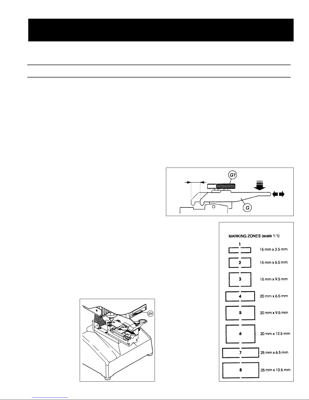
5. Clamp item to be marked with the key locking
jaw (G) located on the clamp slide (E). The
clamp should
be in the out
(extended or
tracking)
position (See
Fig. 1). The
top (head) of
the item must
be placed
against the
stop (See Fig.
4). Larger
objects may
require repositioning of the top clamp slide by
means of slide locking knob (F). If there is a
groove (mill) in the item being marked, position the clamping jaw by loosening the jaw
locking knob (G1). Place the back of the key
(opposite blade) against the left or right hand
stop depending on the side being marked.
Center the item if it does not have a groove.
Position the key-locking jaw (G) and then
tighten the jaw locking knob (G1) to lock the
settings in place (See Fig 2).
6. Select <F8> for
Tracking.
Make sure that
the slide clamp
assembly is in
the out, or
tracking, position. Turn the
clear plastic
slide (P) over
the jaw. A red
colored laser
light now outlines the area
where marking
will occur.
Move the
marking zone
to the desired
location on
the object to
be marked by
means of the
arrow keys
Fig. 2
Fig. 3
Fig. 1
Page 2
located on your keyboard. Select a marking
zone from the eight available on the tracking
disk (D1) Rotating this disk will display the
different images available (See Fig. 3). At this
time, ensure the number of the zone selected
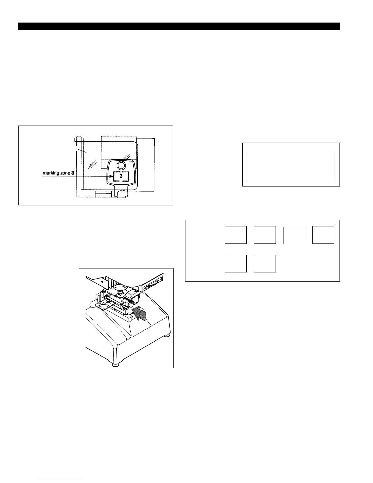
(See Fig. 4) is displayed on the tracking information screen of the Marker 2000 display.
The + and - keys on the keyboard change the
selection. When correct, press <F10>.
7. Press <F7> for text entry and four lines are
displayed. By pressing enter after keying in
the desired information you can move down a
line. When you have completed the text press
<F10>.
8. T urn the clear plastic slide back off the jaw. If
the information displayed is correct push the
jaw back to the in (Marking) position (See
Fig. 5) until it
locks in place.
Press <F10>
for Marking. If
a problem
occurs during
marking,
action may be
halted by
pressing the
<ESC> key.
9. After the job is
completed,
select the <ESC> button to set up the next task.
If you wish to save the original information
select “Y” for yes and this file will be saved
under the name you select. <Press F10>. This
file name is then listed under “Local Marking”.
To access this file at a later time, select <F2>
(List of Models). At the screen display listing
all models, pressing <ESC> will allow you to
start a new job. If you select “N” for No, you
will be at Step 4 of this guide.
10.Refer to the Troubleshooting section on page
four of this guide if problems are experienced.
If the problem is not listed, check the operations manual or contact technical support at
Ilco Unican.
SPECIAL MARKING
You may change either direction or orientation of
your marking. At the marking information screen
(See Fig. 6) press the tab key on your keyboard
until you reach
the selection you
wish to change.
Press the space
more for the
desired direction
or orientation. Options available are illustrated
in Fig. 7.
When selections have been made, continue at
Step 5 of this guide.
2
Fig. 5
Fig. 4
Slide = 3
Side = LH
Dire. = Hor
Pcs. = 1 of 1
Clamp = C1
Orie. = 0
AutoF - [x]
Fig. 6
SILCA
SILCA
SILCA
SILCA
SILCA
S
I
L
C
A
0 90 180 270
HORIZONTAL VERTICAL
direction:
orientation
Fig. 7
Page 3

3
A marking punch
B display
C marking depth regulation ring
D tracking device
D1 tracking disk
E clamp slide
F slide locking knob
G key locking jaw
G1 jaw locking knob
H head unit
I master switch
L feeder outlet
M keyboard outlet
N serial port
O clamp sensor
P glass slide diffuser
P1 glass slide diffuser knob
Page 4

4
1. Marking depth is too shallow or deep
Cause: Marking punch ring is not adjust-
ed properly.
Solution: Change setting (See figure 8 ).
Clockwise will decrease and
counter clockwise will increase
the punching pressure.
2. Text is marked in an area not selected with
the dial.
Cause: The data registered on the infor-
mation screen regarding slide
number is different than the box
selected from the dial.
Solution: Check the box selected on the dial
and verify the same slide number
is selected on the information
screen. If not change this slide
number with the + or - key.
3. When marking, the
object moves from the
original position, the
object is not being held
tightly, the object will
not fit in the clamp correctly.
Cause: The object is
not being held
correctly .
Solution: Ensure that
the lateral
adjustment
clamp is
positioned properly. If not,
loosen the locking knob and
adjust accordingly (See Fig. 9).
Also check that the vertical jaw
slide is in the correct position.
For more clearance loosen the
knob (F) and reposition (See Fig.
10). Make sure knob (F) is tight
before marking.
4. Unreadable text
Cause: Autoformat is not selected.
Solution: Check to see if the Autoformat
option located on the general
information screen is selected
(Marked with an X). If not, select
it to ensure that scaling will occur .
5. When preparing to Mark object, the display
reads, “Marking in Progress, Clamp out of
position”.
Cause: Clamp is in the forward (tracking
position).
Solution: Push clamp to the back (marking
position).
Troubleshooting Guide
Fig. 8
Fig. 9
Fig. 10
USA: 400 Jeffreys Rd., P.O. Box 2627, Rocky Mount, NC 27802-2627 • Tel.: (252) 446-3321 • FAX: (252) 446-4702
Canada: 7301 Decarie Blvd., Montreal, Que. H4P 2G7 • Tel.: (514) 735-5411 • FAX: (514) 735-8707
Form No. 2442/E/997-X
 Loading...